

2940-106
HYDRAULIC COMPRESSOR
2565-779 03/2014
YETTER MANUFACTURING CO.
FOUNDED 1930
Colchester, IL 62326-0358
Toll free: 800/447-5777
309/776-3222 (Fax)
Website: www.yetterco.com
E-mail: info@yetterco.com

FOREWARD
You’ve just joined an exclusive but rapidly growing club.
For our part, we want to welcome you to the group and thank you for buying a Yetter product.
We hope your new Yetter products will help you achieve both goals-increase your productivity and increase
your efficiency so that you may generate more profit.
This operator’s manual has been designed into four major sections: Foreword, Safety Precautions,
Installation Instructions and Parts Breakdown.
This SAFETY ALERT SYMBOL indicates important safety messages in the manual. When you
see this symbol, be alert to the possibility of PERSONAL INJURY and carefully read the
message that follows.
The word NOTE is used to convey information that is out of context with the manual text. It contains special
information such as specifications, techniques and reference information of a supplementary nature.
The word IMPORTANT is used in the text when immediate damage will occur to the machine due to
improper technique or operation. Important will apply to the same information as specified by note only of
an immediate and urgent nature.
It is the responsibility of the user to read the operator’s manual and comply with the safe and correct
operating procedure and to lubricate and maintain the product according to the maintenance schedule in
the operator’s manual.
The user is responsible for inspecting his machine and for having parts repaired or replaced when
continued use of the product would cause damage or excessive wear to the other parts.
It is the user’s responsibility to deliver his machine to the Yetter dealer who sold him the product for service
or replacement of defective parts, which are covered by the warranty policy.
If you are unable to understand or follow the instructions provided in this publication, consult your local
Yetter dealer or contact:
YETTER MANUFACTURING CO.
309/776-4111
800/447-5777
309/776-3222 (FAX)
Website: www.yetterco.com
E-mail: info@yetterco.com
WARRANTY
Yetter Manufacturing warrants all products manufactured and sold by it against defects in material. This
warranty being expressly limited to replacement at the factory of such parts or products as shall appear to
be defective after inspection. This warranty does not obligate the Company to bear cost of labor in
replacement of parts. It is the policy of the Company to make improvements without incurring obligations to
add them to any unit already sold. No warranty is made or authorized to be made, other than herein set
forth. This warranty is in effect for one year after purchase.
DEALER: ________________________________________
Yetter Manufacturing warrants its own products only and cannot be responsible for damages to
equipment on which mounted.
2

SAFETY
A brief description of signal words that may be used in this manual:
CAUTION:
practices.
Used as a general reminder of good safety practices or to direct attention to unsafe
WARNING:
Denotes a specific potential hazard.
DANGER:
You can make your farm a safer place to live and work if you observe the safety precautions given. Study
these precautions carefully and insist that those working with you and for you follow them.
Finally, remember this: an accident is usually caused by someone’s carelessness, neglect or oversight.
Denotes the most serious specific potential hazard.
SAFETY PRECAUTIONS
WARNING
Never clean, lubricate or adjust a machine that is in motion. Always lower or block the implement before
performing service.
If the machine must be serviced in the raised position, jack or block it up to prevent it from accidentally
falling and injuring someone.
Do not allow riders on the tractor or implement.
Use speeds and caution dictated by the terrain being traversed. Do not operate on any slope steep
enough to cause tipping or loss of control.
Be sure all personnel are clear of the immediate area before operating.
Read and understand the operator’s manual and require all other persons who will operate the equipment
to do the same.
Be familiar with all tractors and implement controls and be prepared to stop engine and implements
quickly in an emergency.
CAUTION
Consult your implement and tractor operator’s manual for correct and safe operating practices.
Beware of towed implement width and allow safe clearance.
This product contains pressurized lines and bags, rotating parts, high temperature parts, and sharp
edges. Use extreme caution when working with each condition.
FAILURE TO HEED MAY RESULT IN PERSONAL INJURY OR DEATH.
3

INTRODUCTION
The Yetter 2940-106 Hydraulic Air Compressor converts hydraulic power into compressed air.
Yetter Hydraulic Compressor units are durably constructed and designed for easy integration to
operate the Yetter 2940 Air Adjust System. IF USING THIS COMPRESSOR TO SUPPLY AIR
TO OPERATE ANOTHER SYSTEM, INSTALL A REGULATOR PRIOR TO AIR ENTERING
THAT SYSTEM WITH PROPER REGULATED AIR SETTINGS RECOMMENDED BY OEM
PRODUCT.
SYSTEM REQUIREMENTS:
-The 2940-106 Hydraulic Air Compressor requires 4 gallons per minute maximum
hydraulic flow to operate.
-Lubrication of the pump requires a Grade 111 synthetic or a PAO synthetic compressor
oil. THE PUMP IS SHIPPED EMPTY AND NEEDS OIL BEFORE OPERATING!!!
-Hydraulic oil flow is required to operate the 2940-106 hydraulic compressor’s hydraulic motor.
Different variables will determine the best way to connect into a hydraulic circuit to power the
hydraulic motor. Connecting directly to SCV, teeing into the planter frame
lift/lowering circuit, or teeing into the bulk tank blower circuit are ways of powering the
compressor. Check OEM tractor and planter manual for hydraulic gpm output to make sure
an adequate source is selected.
-Case Drain connection is required to carry the motor case internal leakage directly to
the tractor hydraulic reservoir (sump) with zero pressure. This oil serves to lubricate
and cool motor components not directly exposed to the working oil. It is normal to
have seepage from this fitting when disconnected from the tractor to protect the motor seals
from thermal expansion. If the tractor is not equipped with a female flat face case drain
coupler, then one must be sourced through a dealer or hydraulic supplier.
TABLE OF CONTENTS
FORWARD…………………………………………………………………….2
SAFETY………………………………………………………………………..3
INTRODUCTION AND SYSTEM REQUIREMENTS…….……………….4
BOLT TORQUE……………………………………………………………….5
EXTERNAL DIAGRAM…………………………………………………….6-7
HYDRAULIC FITTINGS CHART………………………………….…...……8
QUICK START GUIDE………………………………………………………9
COMPRESSOR INSTALLATION GUIDE………………………………..10
HYDRAULIC CONNECTION GUIDE…………………………………11-12
COMMUNICATION HARNESS INSTALLATION GUIDE………………13
PLUMBING AIR LINE GUIDE …………………………………………….14
HARNESS AND PLUMBING DIAGRAM………………………………….15
MAINTENANCE………………………………………………………….16-17
PART IDENTIFICATION………………………………………………..18-23
TROUBLESHOOTING………………………………………………………24
4
Mounting bolts and hardware
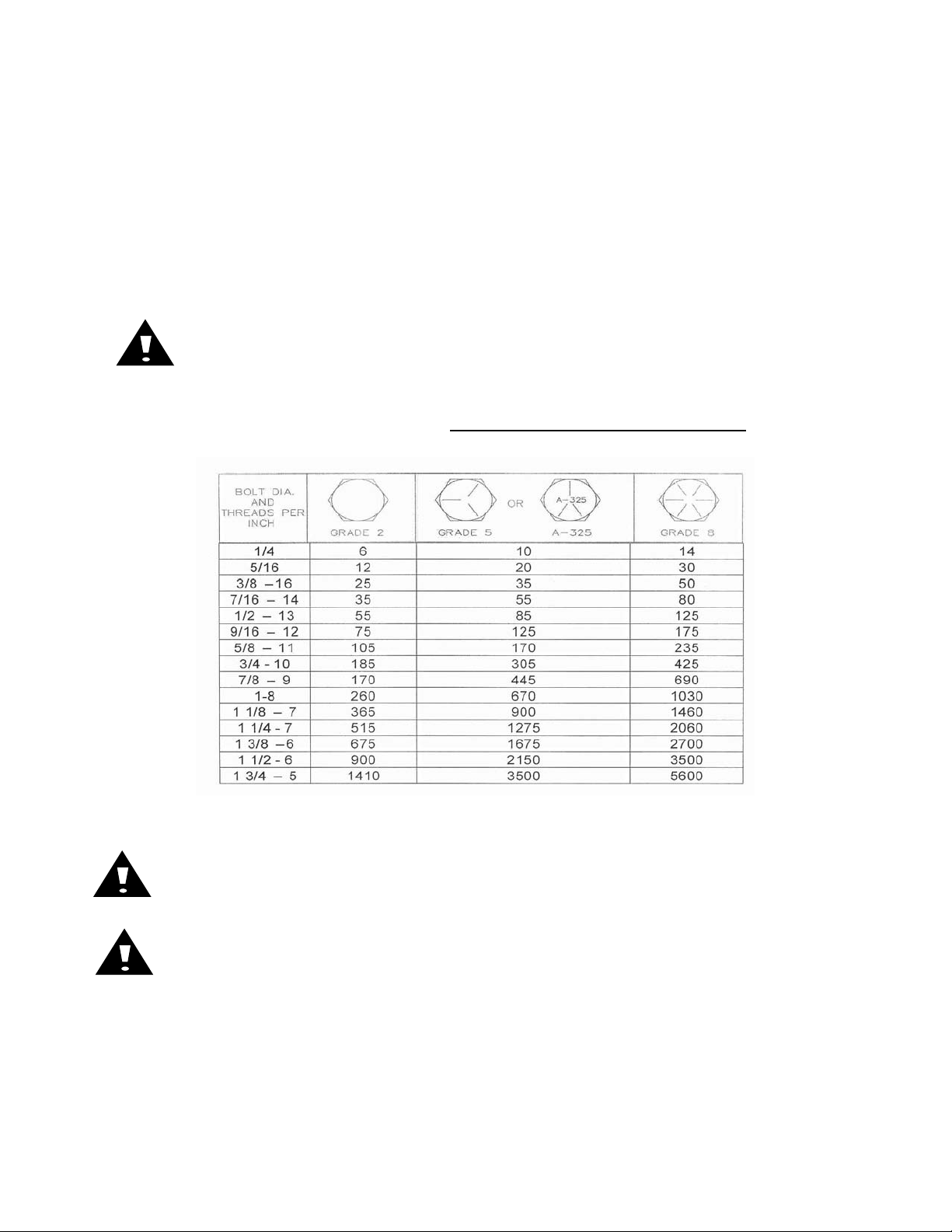
BOLT TORQUE
Before operating the Yetter Hydraulic Compressor for the first time, check to be sure that all hardware is
tight. Check all hardware again after approximately 50 hours of operation and at the beginning of each
planting season.
All hardware used on the Yetter Hydraulic Compressor is Grade 5 unless otherwise noted. Grade 5 cap
screws are marked with three radial lines on the head. If hardware must be replaced, be sure to replace
it with hardware of equal size, strength and thread type. Refer to the torque values chart when tightening
hardware.
Important: Over tightening hardware can cause as much damage as when under
tightening. Tightening hardware beyond the recommended range can reduce its shock load
capacity.
The chart below is a guide for proper torque. Use it unless a specified torque is called out
elsewhere in the manual. Torque is the force you apply to the wrench handle or the cheater
bar, times the length of the handle or bar. Use a torque wrench whenever possible.
The following table shows torque in ft. lbs. for coarse thread hardware.
Lubricate all bearings and moving parts as assembled and make certain that they work freely.
WARNING: Never work around the toolbar/implement while in a raised position without using
safety lockups.
CAUTION: The Residue manager attachments are very heavy. Pay extra attention to lifting
techniques while handling and or maneuvering the opener during assembly. Failure to do so
may lead to personal injury.
5
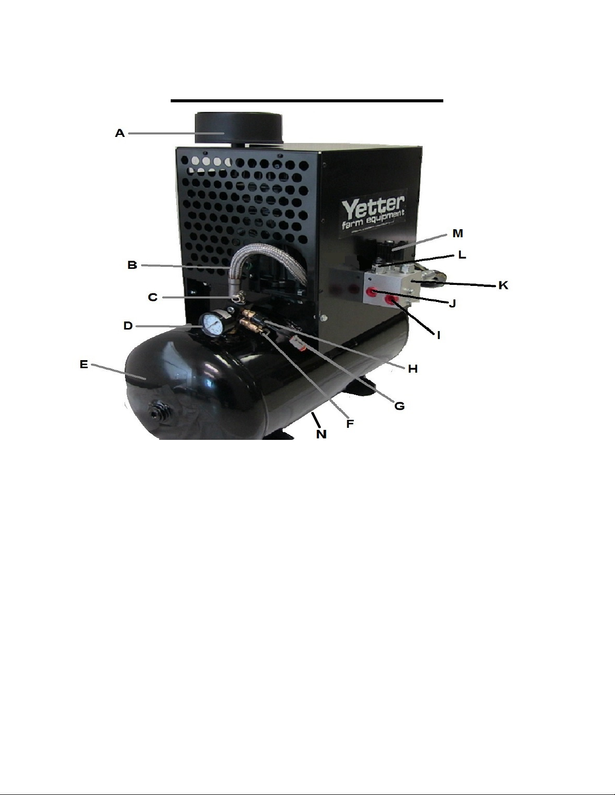
EXTERNAL DIAGRAM
Item Description QTY
A Air Filter 1
B Compressor Pressure Air Line 1
C Output Elbow Fitting 1
D Tank Pressure Gauge 1
E Tank, 12 GAL 1
F Pressure Relief Valve 1
G Pressure Switch Connector 1
H Pressure Switch 1
I Hydraulic Return to Tank Port -8 ORFS 1
J Hydraulic Pressure Inlet Port -6 ORFS 1
K Hydraulic Control Block 1
L Flow Control Valve 1
M Hydraulic On/Off valve 1
N Tank Drain (valve not shown) 1
6
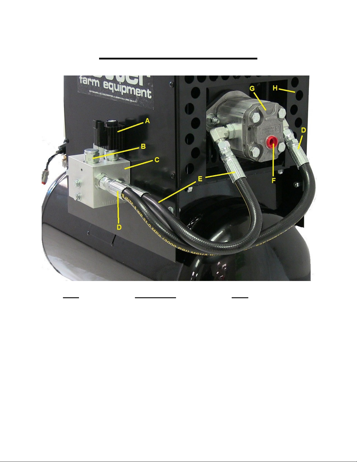
EXTERNAL DIAGRAM
Item Description QTY
A Hydraulic On/Off Valve 1
B Check Valve 1
C Hydraulic Control Block 1
D Return to Tank Hose 1
E Inlet hose 1
F Case Drain Port -6 ORFS 1
G Hydraulic motor 1
H Housing Assembly 1
7
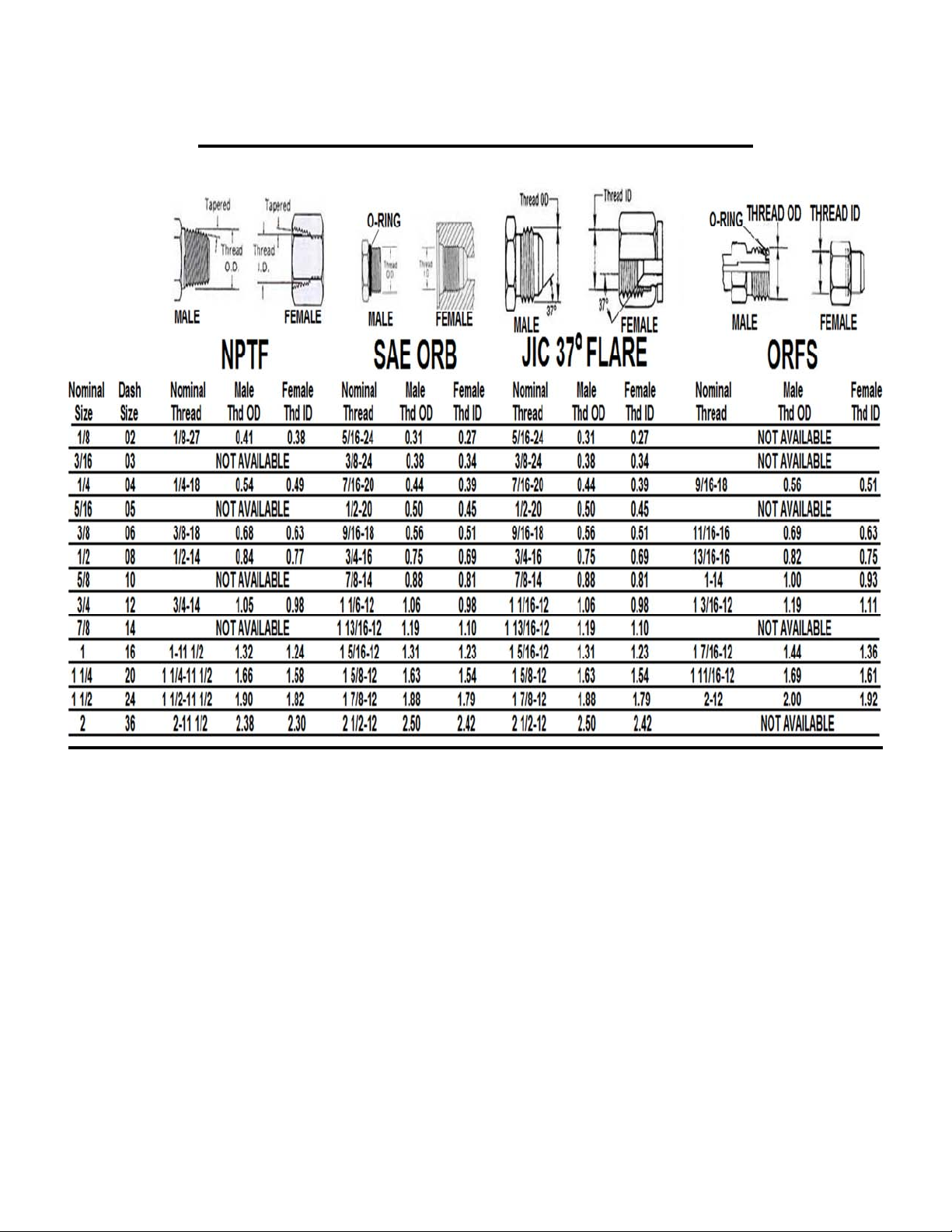
Hydraulic Fittings Identification Chart
-Due to common threads, mismatching can happen and could result in leaks and pressure loss
-Be sure to verify which style and use dash sizes when ordering replacement parts
-NPTF is easily recognizable and looks like regular pipe threads. It is not recommended for hydraulic systems
but does exist on some agriculture equipment
-SAE ORB is recommended by the NFPA for optimal leakage control in medium and high pressure hydraulic systems.
The male fitting has a straight thread and O-ring. The female port has a straight thread, a machined surface (minimum
spotface) and a chamfer to accept the O-ring. The seal takes place by compressing the O-ring in the chamfer. The
threads hold the connection mechanically.
-JIC 37 Degree Flare fittings have a 37° cone seat on the female adapter and a 37° flare on the male adapter. This cone
seat and flare allows for a complete mechanical seal between the male and female fitting. Teflon tape on threads is not
required.
-ORFS (O-Ring Face Seal) adapter fittings use a straight thread and have a machined groove in the face of the male
fitting to accept the O-ring. This O-ring is compressed against the flat face of the female fitting for a leak proof
connection. ORFS are one of the newest types of hydraulic fittings.
8

Quick Start Guide
Step 1: Preparing Hydraulic Compressor for Installation
After removing the hydraulic compressor from the shipping crate, remove cap from elbow fitting
and install air filter assembly securely. Next, remove screen on housing on the side of the sight
glass(same side as pressure gauge) and fill compressor pump with oil until oil is in middle of
sight glass. See page 16 for further information on filter installment and oil filling.
Step 2: Hydraulic Compressor Installation
Begin the installation process by finding a safe location to mount the 2940-106 hydraulic
compressor on the planter. Placement will vary depending on make and model of your planter.
The 2940-085 kit is for mounting on a 2 point hitch. The 2940-086 is a universal mount or can
be used for mounting on the draft tube. The 2940-090 kit is for mounting to a 8”X12” bar and the
2940-091 to mount to a 8”X16” bar. In some situations, a mounting bracket may need to be
built. See page 10 for more detailed information on hydraulic compressor installation.
Step 3: Hydraulic Connection
In order to operate the hydraulic compressor, a connection to a hydraulic circuit must be made.
The 2 most common places to tie into a hydraulic circuit are at the rear of the tractor at an open
SCV port or teeing into the frame lift/CCS circuit on a John Deere set up. CNH planters must
use an open SCV port on the tractor for the hydraulic connection. Never use a PTO driven
hydraulic pump circuit or Bulk Fill blower circuit on a CNH planter. The case drain will also
need to be connected. See page 12 for more detailed information on making the proper
connection to fit your situation.
Step 4: Communication Harness Installation
Communication between the 2940-103 pneumatic controller and the 2940-106 hydraulic
compressor happen by installing a series of harnesses. The 2940-106 should have a Y harness,
one end plugging into the 2 pin hydraulic on/off valve connector, one end plugging into the 2 pin
pressure switch connector, and the other end (4 pin connector) connects to the 2940-182 or
2940-189 and routes to the connector coming out of the 2940-103. See page 13 for more
detailed information.
Step 5: Plumbing Air Line
Using a 250psi rated 3/8” air line (Yetter part number 2940-367), route line safely from 3/8” PTC
fitting on water trap side(not regulator side) of the 2940-415 water separator assembly to the
3/8” PTC output elbow fitting (labeled C on page 6) of the hydraulic compressor. Use 2565-773
air adjust manual for row unit installation and other airline plumbing and electrical harness
routing. See page 14 for more detailed information.
9

COMPRESSOR INSTALLATION GUIDE
Mounting Kits
2940-085 2 Point Hitch Mount Kit
2940-086 Draft Tube or Universal Mount Kit
2940-090 8X12 Bar Hyd. Comp. Mount Kit
2940-091 8X16 Bar Hyd. Comp. Mount Kit
2940-091
10

HYDRAULIC CONNECTION GUIDE
2940-088
(PLANTER)
Qty in kit Qty in kit
4 2 2515-324 ELBOW 90 DEG, 3/4 SAE TO -6 JIC
2 2515-327 ADAPTER 3/4-16 SAE TO -6 JIC
3 2515-329 ADAPTER REDUCER, -8 F TO -6 M JIC
2 2 2515-411 ELBOW 90 DEG 3/4 SAE TO -8JIC
3 1 2515-425 TEE TEE 3/4 SAE
2 2515-428 ELBOW JIC-6 90 DEGREE SWIVEL
3 2515-430 TEE JIC-8 RUN TEE
2 2 2515-431 ADAPTER 9/16 SAE TO -6 JIC ADAPTER
1 2515-432 ELBOW JIC-8 90 DEGREE SWIVEL
1 1 2515-433 ELBOW 9/16 SAE to -6 JIC 90 DEGREE
2 2 2515-831 HOSE 3/8 10FT HOSE -6 JIC F
1 1 2515-832 HOSE 1/2 10FT HOSE -8 JIC F
1 1 2515-833 ADAPTER 3/4 SAE TO -8 JIC
2 2515-834 COUPLER PIONEER, POPPET STYLE
2940-089 kit
(STAND ALONE)
Hose and Fitting Kits
Part # Part Name Description
11

BULKHEAD BLOWER CIRCUIT
TEEING BEHIND PIONEER COUPLER
SCV DIRECT CASE DRAIN
NOTE: THESE ARE EXAMPLES ONLY. USE YOUR BEST
JUDGEMENT TO FIT YOUR SITUATION
PTO DRIVEN HYDRAULIC PUMP CIRCIUTS ARE NOT AN
ADEQUATE SOURCE TO OPERATE THE YETTER
HYDRAULIC COMPRESSOR
12

COMMUNICATION HARNESS INSTALLATION
WHEN ROUTING HARNESSING, BE SURE TO KEEP CLEAR
OF PINCH POINTS, ROTATING PARTS, ETC.
13

PLUMBING AIR LINE GUIDE
BE SURE TO ROUTE ALL AIR TUBING SAFELY STAYING CLEAR OF ALL
ROTATING PARTS, PINCH PINCH, ETC.
14

HARNESS & PLUMBING DIAGRAM
15

MAINTENANCE
CLEANING OR REPLACING THE 2940-106 AIR FILTER
Filter cleanliness is critical to maintain the performance and service life of the
compressor. Recommendations for cleaning are daily and replace every 200 hours
STEP 1: REMOVE WING NUT AND FILTER COVER
STEP 2: REMOVE FILTER (IF CLEANING, TAP FILTER ON SOLID SURFACE TO REMOVE
DIRT FROM PLEATS AND CLEAN FILTER BASE) DO NOT USE COMPRESSED AIR TO
CLEAN FILTER!
STEP 3: INSTALL NEW OR CLEANED FILTER
STEP 4: INSTALL WING NUT AND FILTER COVER REMOVED IN STEP 1
OR at beginning of every planting season.
16

MAINTENANCE
WARNING:
Keep extremities out of the compressor housing when compressor is running, has potential
to run, or recently shut off as there are rotating and high temperature parts that my cause
injury. Always turn tractor off and disconnect power before performing any maintenance
LUBRICATION:
The compressor is shipped empty of pump lubrication and needs oil added before operation.
Provided is a 1 Liter bottle of grade 111 synthetic. Add oil until oil level is seen half way up on
the sight glass. Yetter part number for purchasing new bottle is 2940-550.
GUARDS:
Always ensure the housing and guards are in place during operation.
AIR FILTER CARTRIDGE:
Yetter part number 2940-549. Order as needed.
DAILY
Check oil level and fill as needed
Check air filter cleanliness and clean/replace as needed
Check hoses for fluid leaks and replace/fix as needed
Check air lines for air leaks and replace/fix as needed
Drain tank pressure with Tank Drain Valve(labeled N on page 6) to allow moisture to drain
SEASONALLY/200 COMPRESSOR HOURS
Change compressor oil
Change inlet air filter
Check fluid hoses and air lines for weakness or weathering and replace as needed.
Check hydraulic fittings for proper connections with no leaks, replace as needed.
.
MAINTENANCE SCHEDULE GUIDE
FIRST OIL CHANGE SHOULD TAKE PLACE AFTER
APPROXIMATELY 50 RUNNING HOURS
17

2940-085
PARTS IDENTIFICATION
18

2940-086
PARTS IDENTIFICATION
19

2940-090 & 2940-091
PARTS IDENTIFICATION
20

PARTS IDENTIFICATION
2940-106
21

PARTS IDENTIFICATION
BALLOON
1
2
3
4
5
6
7
8
9
10
11
12
13
14
DESC
CHECK VALVE
TANK (12 GALLON)
VALVE BLOCK
FLOW CONTROL
VALVE
FRAME
PUMP
COUPLER
MOTOR
COVER
TANK ELBOW FITTING
INLET ELBOW FITTING
FAN
FILTER
15
16
17
18
19
20
21
22
23
24
25
FILTER ELBOW
BACK GUARD
AIR MANIFOLD
PRESSURE RELIEF VALVE
PRESSURE SWITCH
GAUGE
AIR ELBOW FITTING
TANK HOSE
INLET HOSE
PRESSURE LINE
YETTER DECAL
PART REFERENCE ONLY
22

PARTS IDENTIFICATION
PART REFERENCE ONLY
23

COMPRESSOR TROUBLESHOOTING
PROBLEM
CAUSE
CORRECTIVE ACTION
compressor
will not
operate/run
compressor
runs
nonstop, will
not build
pressure, or
stalls:
compressor
shuts down
with air
demand
1)system is not turned on
2)compressor communication harness not
installed
3)hydraulics installed improperly
4)compressor not below 125psi
5)compressor locked up/unlubricated
1)severe air leak
2)insufficient hydraulic pressure or flow
3)hydraulic reservoir low
4)air filter plugged
5)faulty Pressure Switch
6)air manifold valve stuck closed
1)compressor temperature to high
2)compressor runs continuously for 15 minutes
3)insufficient hydraulic flow
4)worn hydraulic motor
1)with cab controller on, press enter to turn system
on(button will be green)
2)install harness between compressor and 2940-103 control
box
3)check hydraulic connection for proper installment and flow
4)compressor will not recover until below 125psi
5)order new compressor
1)check all fittings and air lines for leaks
2)ensure adequate pressure and flow from connected circuit
3)add proper hydraulic oil to recommended level
4)clean or replace
5)replace
6)clean or replace
1)turn system off and check for leaks
2)press enter to reset message alert and check for leaks
3)ensure adequate hydraulic pressure and flow or call
Yetter service department(800-447-5777)
4)replace
2565-779 MANUAL 03/2014
24
 Loading...