

Page 1

2940-010 COULTER & RESIDUE
MANAGER COMBO
INSTALLATION GUIDE
2565-778 01/2014
YETTER MANUFACTURING CO.
*PATENT PENDING*
FOUNDED 1930
Colchester, IL 62326-0358
Toll free: 800/447-5777
309/776-3222 (Fax)
Website: www.yetterco.com
E-mail: info@yetterco.com
1
Page 2

FOREWARD
You’ve just joined an exclusive but rapidly growing club.
For our part, we want to welcome you to the group and thank you for buying a Yetter product.
We hope your new Yetter products will help you achieve both goals-increase your productivity
and increase your efficiency so that you may generate more profit.
This operator’s manual has been designed into four major sections: Foreword, Safety
Precautions, Installation Instructions and Parts Breakdown.
This SAFETY ALERT SYMBOL indicates important safety messages in the manual.
When you see this symbol, be alert to the possibility of PERSONAL INJURY and
carefully read the message that follows.
The word NOTE is used to convey information that is out of context with the manual text. It
contains special information such as specifications, techniques and reference information of a
supplementary nature.
The word IMPORTANT is used in the text when immediate damage will occur to the machine due
to improper technique or operation. Important will apply to the same information as specified by
note only of an immediate and urgent nature.
It is the responsibility of the user to read the operator’s manual and comply with the safe and
correct operating procedure and to lubricate and maintain the product according to the
maintenance schedule in the operator’s manual.
The user is responsible for inspecting his machine and for having parts repaired or replaced when
continued use of the product would cause damage or excessive wear to the other parts.
It is the user’s responsibility to deliver his machine to the Yetter dealer who sold him the product
for service or replacement of defective parts, which are covered by the warranty policy.
If you are unable to understand or follow the instructions provided in this publication, consult your
local Yetter dealer or contact:
YETTER MANUFACTURING CO.
309/776-4111
800/447-5777
309/776-3222 (FAX)
Website: www.yetterco.com
E-mail: info@yetterco.com
WARRANTY
Yetter Manufacturing warrants all products manufactured and sold by it against defects in
material. This warranty being expressly limited to replacement at the factory of such parts or
products as shall appear to be defective after inspection. This warranty does not obligate the
Company to bear cost of labor in replacement of parts. It is the policy of the Company to make
improvements without incurring obligations to add them to any unit already sold. No warranty is
made or authorized to be made, other than herein set forth. This warranty is in effect for one year
after purchase.
DEALER: ________________________________________
Yetter Manufacturing warrants its own products only and cannot be responsible for
damages to equipment on which mounted.
2
Page 3

SAFETY
A brief description of signal words that may be used in this manual:
CAUTION: Used as a general reminder of good safety practices or to direct attention to unsafe
practices.
WARNING: Denotes a specific potential hazard.
DANGER: Denotes the most serious specific potential hazard.
You can make your farm a safer place to live and work if you observe the safety precautions
given. Study these precautions carefully and insist that those working with you and for you follow
them.
Finally, remember this: an accident is usually caused by someone’s carelessness, neglect or
oversight.
SAFETY PRECAUTIONS
WARNING
Never clean, lubricate or adjust a machine that is in motion. Always lower or block the implement
before performing service.
If the machine must be serviced in the raised position, jack or block it up to prevent it from
accidentally falling and injuring someone.
Do not allow riders on the tractor or implement.
Use speeds and caution dictated by the terrain being traversed. Do not operate on any slope
steep enough to cause tipping or loss of control.
Be sure all personnel are clear of the immediate area before operating.
Read and understand the operator’s manual and require all other persons who will operate the
equipment to do the same.
Be familiar with all tractors and implement controls and be prepared to stop engine and
implements quickly in an emergency.
CAUTION
Consult your implement and tractor operator’s manual for correct and safe operating practices.
Beware of towed implement width and allow safe clearance.
FAILURE TO HEED MAY RESULT IN PERSONAL INJURY OR DEATH.
3
Page 4

INTRODUCTION
The 2940-010 Unit Mounted Conservation Coulter and Residue Manager have been designed as
a ‘universal’ fitment for several makes of planter units.
The 2940-191 assembly of the 2940-010 has a mounting bracket that will correctly attach to most
planters including John Deere, Kinze, and Agco White. Several different styles of blades are
available for every tillage practice, every soil type, and every residue condition, so you can
choose the one that’s right for you.
TABLE OF CONTENTS
Cover Page…………………………..……………………………1
Foreward…………………………………………………2
Safety Precautions and Warning………………………3
Introduction & Blade Options…………………………..4
Bolt Torque………………………………………………5
Installation Instructions………………………………6-8
Air Line Installation……………………………………...9
Operation & Maintenence………………………....10-11
Part Identification…….………………………….…12-14
4
Page 5

BOLT TORQUE
Mounting bolts and hardware
Before operating the Titan Residue Manager for the first time, check to be sure that all
hardware is tight. Check all hardware again after approximately 50 hours of operation and at the
beginning of each planting season.
All hardware used on the Titan Residue Manager is Grade 5 unless otherwise noted. Grade 5
cap screws are marked with three radial lines on the head. If hardware must be replaced, be
sure to replace it with hardware of equal size, strength and thread type. Refer to the torque
values chart when tightening hardware.
The chart below is a guide for proper torque. Use it unless a specified
torque is called out elsewhere in the manual.
Torque is the force you apply to the wrench handle or the cheater bar,
times the length of the handle or bar. Use a torque wrench whenever
possible.
The following table shows torque in ft. lbs. for coarse thread hardware.
Important: Over tightening hardware can cause as much damage as when under
tightening. Tightening hardware beyond the recommended range can reduce its
shock load capacity.
Lubricate all bearings and moving parts as assembled and make certain that they work freely.
WARNING: Never work around the toolbar/implement while in a raised position without
using safety lockups.
CAUTION: The Residue manager attachments are very heavy. Pay extra attention to
lifting techniques while handling and or maneuvering the opener during assembly.
Failure to do so may lead to personal injury.
5
Page 6

INSTALLATION INSTRUCTIONS
STEP 1: When installing the 2940-191 combo air assembly to the row unit, a
quantity of 3-1/2”x1 ½” bolts is used. Each OEM row unit will have 3
holes that line up for installment to make the 2940 coulter combo
mount level.
STEP 2: For easier install, make sure elbow swivels by placing 11/16”
wrench on NPT end and turning elbow by hand a few rotations.
Once fittings are started on the air bag, tighten until thread tape
almost disappears. OVER TIGHTENING WILL STRIP THREADS &
CAUSE AIR LEAK!
6
Page 7

INSTALLATION INSTRUCTIONS
15” PLANTER BLADES 15” PLANTER BLADES
JD 7000 AND KINZE PLANTERS JD 1700, 7200, & 7300 PLANTERS
ALL WHITE 6000 PLANTERS PRO AND PLUS SERIES
BOLT POSITION # BOLT POSITION #
1) 1-1/2” ABOVE 1) 1” ABOVE
2) 1” ABOVE 2) 5/8” ABOVE
3) ½” ABOVE 3) EVEN
4) ½” BELOW 4) 7/8” BELOW
CONT’D
STEP 3: Install coulter blade using a quantity of 4-1/2”x1 ¼” carriage bolts.
Make sure shoulder on carriage bolt shoulders rest inside of square
hole on the hub. The blade MUST be on the hub before mounting
the coulter arm. IF USING SETTING #2 ON CHART AT THE
BOTTOM OF THE PAGE FOR DEPTH, LEAVE THE BLADE
LOOSE ON THE HUB IN ORDER TO INSTALL COULTER ARM
MOUNTING BOLT CLOSEST TO THE BLADE.
COULTER ARM
INSTALLATION INSTRUCTIONS
USING A 16” COULTER BLADE
NOTE: THIS IS A REFERENCE GUIDE TABLE. ALL MEASUREMENTS WERE TAKEN
WITH ROW UNIT AND PLANTER FRAME LEVEL/PARALLEL TO THE SOIL.
7
Page 8

STEP 4: Install coulter and arm assembly in desired setting using a quantity
of 2-5/8”x2 bolts and 2-5/8” hex jam locknuts.
Adjustment: Adjust coulter blade depth equal to or above the planter opener
blades. Adjust the blade depth as required for blade wear. Planter blades that are
worn to 14 ¼” or smaller in diameter should be replaced. Example: 14 ¼” blades
will have a 3/8” shallower planting depth than 15” blades at the same gauge
wheel adjustment setting.
STEP 5: Install 5/8” jam nut on the 5/8”x3 square head down stop bolt. Set
down stop to desired setting and then tighten jam nut to hold in
place.
STEP 6: Properly install row cleaner wheels so that wheel teeth point up
when entering field debris.
8
Page 9

AIR LINE INSTALLATION
Route up pressure (blue) lines from elbow fittings toward the face
plate of the row unit. Zip tie air lines to the holes provided (as shown
in picture) keeping air lines away from pinch points, rotating parts, or
anything that may cause wear or damage to lines. Up pressure line
will loop around (as shown in picture) and connect to a tee. Safely
route blue air line from the top PTC port of the Tee into the main up
pressure trunk lines.
Route down pressure (black) line from the elbow fitting alongside the
up pressure(blue line) to the main down pressure trunk lines.
9
Page 10

OPERATION
1. Set/mount coulter blades to run perpendicular to the soil. Operation depth and blade
wear can be affected if the coulter is mounted crooked or if the toolbar is not level side to
side.
2. After a few hours of use, check all bolts for tightness and proper torque.
3. After a day of use (10-12 hours) check coulter hubs for loose bearings. There should be no
endplay in the hub bearings allowing the blade to wobble. If necessary, remove
hubcap and cotter pin and adjust the slotted nut to remove wobble, recommended torque
of 15 ft. lbs. and re-insert cotter pin. If the wobble or looseness cannot be corrected, the
bearings, cups and seals will need to be replaced. DO NOT USE WORN OR DAMAGED
PARTS.
MAINTENANCE
LUBRICATION: USE #2 MULTI-PURPOSE LITHIUM GREASE
To ensure longevity and reliability of the Coulter Residue Manager Combo, the recommended
lubrication schedule should be followed using multi-purpose grease at hourly intervals as
indicated.
BEARING ADJUSTMENT:
1. Raise the toolbar until the blade is clear of the ground. Place a safety stand under the
toolbar. Remove the hubcap, cotter pin, slotted nut and washer from the hub assembly.
Remove the blade from the hub assembly.
2. Remove bearing cones and seals from hub.
3. Wash the old grease from the hub, bearing cups, spindle spacers, seals and bearing
cones. Inspect the condition of the bearing cups, cones and seals. Replace if necessary.
4. Apply #2 multi-purpose lithium grease on each bearing. Make sure the space around
each roller is filled. Lubricate the bearing cups.
5. Position the bearing in the cup and install the seal. Lubricate the seal lips and proceed
with reassembly of the removed parts including the blade. Blade bolt torque is 90 to 96 ft.
lbs.
6. Tighten the slotted nut to 15 ft. lbs. or until a definite drag is felt when the blade is
turned by hand. Tighten the nut one slot position to line up the cotter pin hole with a slot.
Secure the nut with a new cotter pin, replace hubcap.
10
Page 11

2940-191 PART IDENTIFICATION
11
Page 12
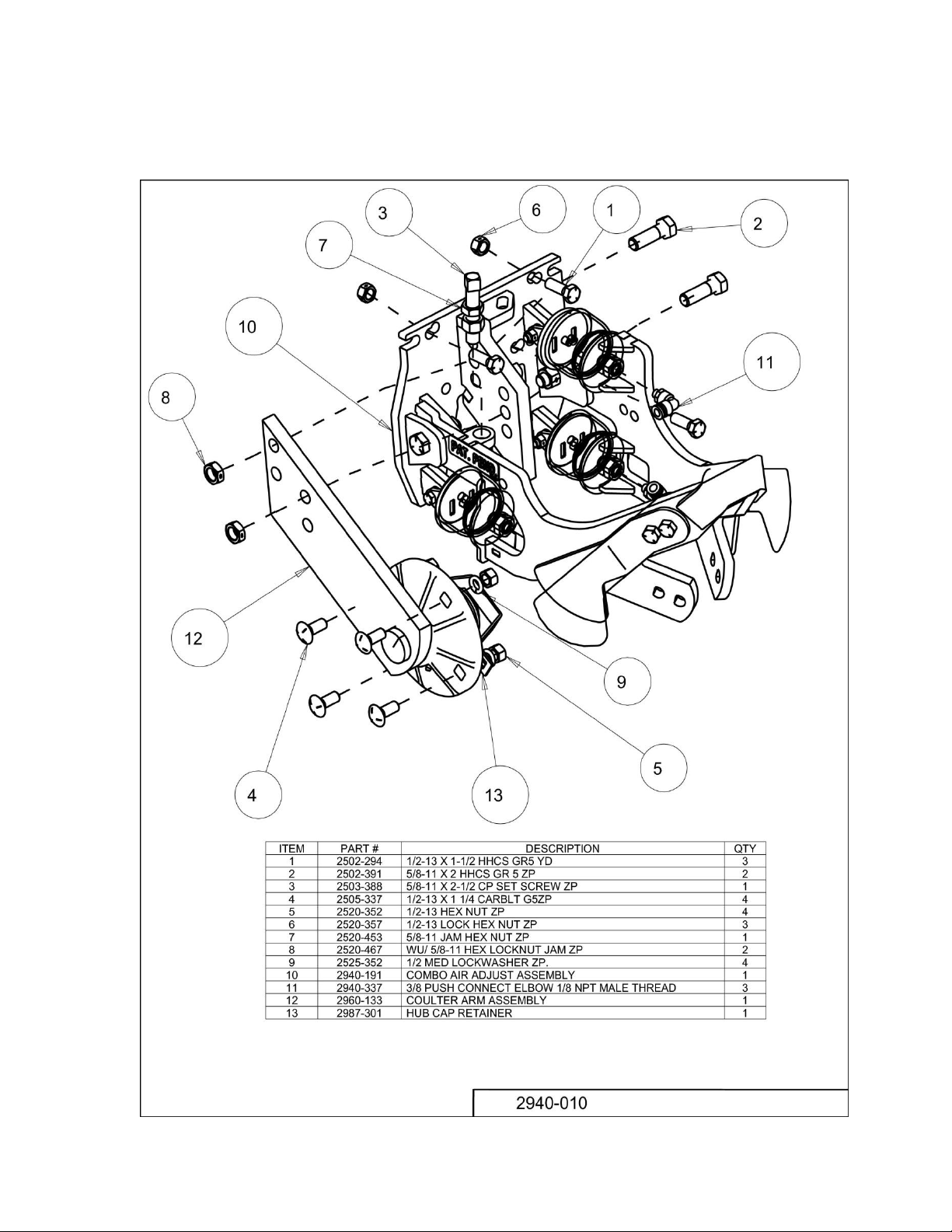
2940-010 PART IDENTIFICATION
12
Page 13

2960-133 PART IDENTIFICATION
13
Page 14

2565-778 01/2014
14
 Loading...