

Page 1

ALL STEER PLUS™ FERTILIZER TOOLBAR
2000 SERIES
ALL STEER PLUS ™ FERTILIZER TOOLBAR
SET-UP AND PARTS MANUAL
YETTER MANUFACTURING CO.
FOUNDED 1930
Colchester, IL 62326-0358
Toll free: 800/447-5777
309/776-3222 (Fax)
Website: www.yetterco.com
E-mail: info@yetterco.com
Page 2

FOREWORD
You’ve just joined an exclusive but rapidly
growing club.
For our part, we want to welcome you to the
group and thank you for buying a Yetter product.
We hope your new Yetter products will help you
achieve both goals-increase your productivity and
increase your efficiency so that you may generate
more profit.
This operator’s manual has been designed into
four major sections: Foreword, Safety
Precautions, Installation Instructions and Parts
Breakdown.
This SAFETY ALERT SYMBOL indicates
important safety messages in the
manual. When you see this symbol,
be alert to the possibility of
PERSONAL INJURY and carefully
read the message that follows.
The word NOTE is used to convey information
that is out of context with the manual text. It
contains special information such as
specifications, techniques and reference
information of a supplementary nature.
The word IMPORTANT is used in the text when
immediate damage will occur to the machine due
to improper technique or operation. Important will
apply to the same information as specified by
note only of an immediate and urgent nature.
It is the responsibility of the user to read the
operator’s manual and comply with the safe and
correct operating procedure and to lubricate and
maintain the product according to the
maintenance schedule in the operator’s manual.
The user is responsible for inspecting his
machine and for having parts repaired or
replaced when continued use of the product
would cause damage or excessive wear to the
other parts.
It is the user’s responsibility to deliver his
machine to the Yetter dealer who sold him the
product for service or replacement of defective
parts, which are covered by the warranty policy.
If you are unable to understand or follow the
instructions provided in this publication, consult
your local Yetter dealer or contact:
YETTER MANUFACTURING CO.
309/776-4111
800/447-5777
309/776-3222 (FAX)
Website: www.yetterco.com
E-mail: info@yetterco.com
WARRANTY
Yetter Manufacturing warrants all products manufactured and sold by it against defects in material. This
warranty being expressly limited to replacement at the factory of such parts or products as shall appear to
be defective after inspection. This warranty does not obligate the Company to bear cost of labor in
replacement of parts. It is the policy of the Company to make improvements without incurring obligations
to add them to any unit already sold. No warranty is made or authorized to be made, other than herein
set forth. This warranty is in effect for one year after purchase.
Dealer ___________________________________________________
Yetter Manufacturing warrants its own products only and cannot be responsible for damages to
equipment on which mounted.
2
Page 3

SAFETY PRECAUTIONS
You can make your farm a safer place to live and work if you observe the safety precautions given. Study these
precautions carefully and insist those working with you and for you follow the precautions.
Finally, remember this an accident is usually caused by someone’s carelessness, neglect or oversight.
CAUTION
Consult your implement and tractor operator’s manual for correct and safe operating practices. Be aware of towed
implement width and allow safe clearance.
CAUTION: SAFETY SIGNS
Safety decals are placed on the implement to alert the operator and others to the risk of personal injury or unsafe
operation during normal operations and servicing.
1. The safety decals must be kept clean and in good condition to ensure that they are legible.
2. Safety decals must be replaced if they are missing or illegible.
3. When components are replaced during repair or servicing, check that the new components include the
necessary safety signs.
4. Replacement safety decals may be obtained from your local dealer.
WARNING
Never clean, lubricate or adjust a machine that is in motion. Always install the transport lock pins and bracket when
transporting for any length of time or on public roadways.
If required to service unit in raised position, be sure to install all transport lock pins and locking bracket.
Be sure the implement is securely pinned before operating.
Do not allow children to operate this equipment.
Do not allow riders on the tractor or implement.
Use speeds and caution dictated by the terrain being traversed. Do not operate on any slope steep enough to cause
tipping or loss of control.
Be sure all personnel are clear of the immediate area before operating.
Read and understand the operator’s manual and require all other persons who will operate the equipment to do the
same.
In operating on public roadways, where legal, be certain all lighting is operating properly and observe all traffic laws.
Ensure slow moving vehicle emblem on tractor is visible.
Maximum towing speed is 20 mph when conditions permit.
Beware of increased stopping distances and control effort when operating with implements attached.
Be familiar with all tractor and implement controls and be prepared to stop engine and implements quickly in an
emergency.
Do not unhitch cart in the raised position with a grain drill attached. Lower unit before unhitching.
Do not trail cart with small trucks, etc. The hitch weight of the cart is in excess of 1000 lbs.
FAILURE TO HEED MAY RESULT IN PERSONAL INJURY OR DEATH.
3
Page 4

TABLE OF CONTENTS
PAGE
FORWARD………………………………………………………….……………2
WARRANTY…………………………………………………………….………..2
SAFETY INFORMATION……….………………………………………..……..3
TABLE OF CONTENTS……..….………………………………………..……..4
GENERAL INFORMATION……………………………………………………..5
TORQUE
RECOMMENDATIONS…………...……………………………………..….…..5
ASSEMBLY INSTRUCTIONS….………………………………..…….…...5-25
OPERATION……………………………………………………..…….……26-32
MAINTENANCE………………………………………………………………...33
PARTS IDENTIFICATION…………………………………………...…….34-49
TROUBLESHOOTING………………………………………………..……….51
WARNING:
using safety lockups.
Never work around the toolbar / implement while in a raised position without
CAUTION:
unit has sharp blades. Extra attention should be paid to lifting techniques while handling and or
maneuvering the units during assembly. Failure to do so may lead to personal injury. Use heavy
gloves while handling the blades during assembly and any time adjustments or maintenance
operations are made to the implement.
THE 2000 SERIES ALL STEER PLUS ™ FERTILIZER TOOLBAR
4
Page 5

ASSEMBLY INSTRUCTIONS
GENERAL INFORMATION
Examine all equipment carefully for damage or shortages.
Lubricate all bearings and moving parts as assembled.
Reference to front, rear, left and right in this installation instruction are made when setting in the
operator’s seat facing direction of forward travel.
BOLT TORQUE
READ THESE INSTRUCTIONS FIRST:
1. Improperly tightened bolts will result in damage, breakage, expense, and down time.
2. Always replace bolts with the specified grade and type.
3. Torque properly before first use of the machine and every 2-4 hours of use until you are sure
bolts are staying tight.
4. The chart below is a guide for proper torque. Use it unless a specified torque is called out
elsewhere in the manual.
5. Torque is the force you apply to the wrench handle or the cheater bar, times the length of the
handle or bar.
6. Use a torque wrench whenever possible.
The following table shows torque in ft. lbs.
5
Page 6

ASSEMBLY INSTRUCTIONS
Step 1. Attach the hinge brackets to the bridge hitch using the (2) hinge pins and 3/8” X 2” roll pin.
Step 2. Attach the hinge brackets to the front axle using the hinge bolting strap, (8) ¾” X 7-1/2” hex bolt
and ¾” lock hex nut.
6
Page 7

ASSEMBLY INSTRUCTIONS
Step 3. Level the Bridge Hitch frame. Install the hitch. Torque bolts to 670 ft/lbs.
ASSEMBLY INSTRUCTIONS
Step 4.
hose holder. Torque to 300 ft/lbs.
Install the safety chain and
7
Page 8

ASSEMBLY INSTRUCTIONS
Step 4. Install the safety chain and hose holder. Torque to 300 ft/lbs.
Step 5. Install the jack assembly to the Bridge Hitch frame. Next, install the jack storage strap to the
Bridge Hitch frame.
8
Page 9
ASSEMBLY INSTRUCTIONS
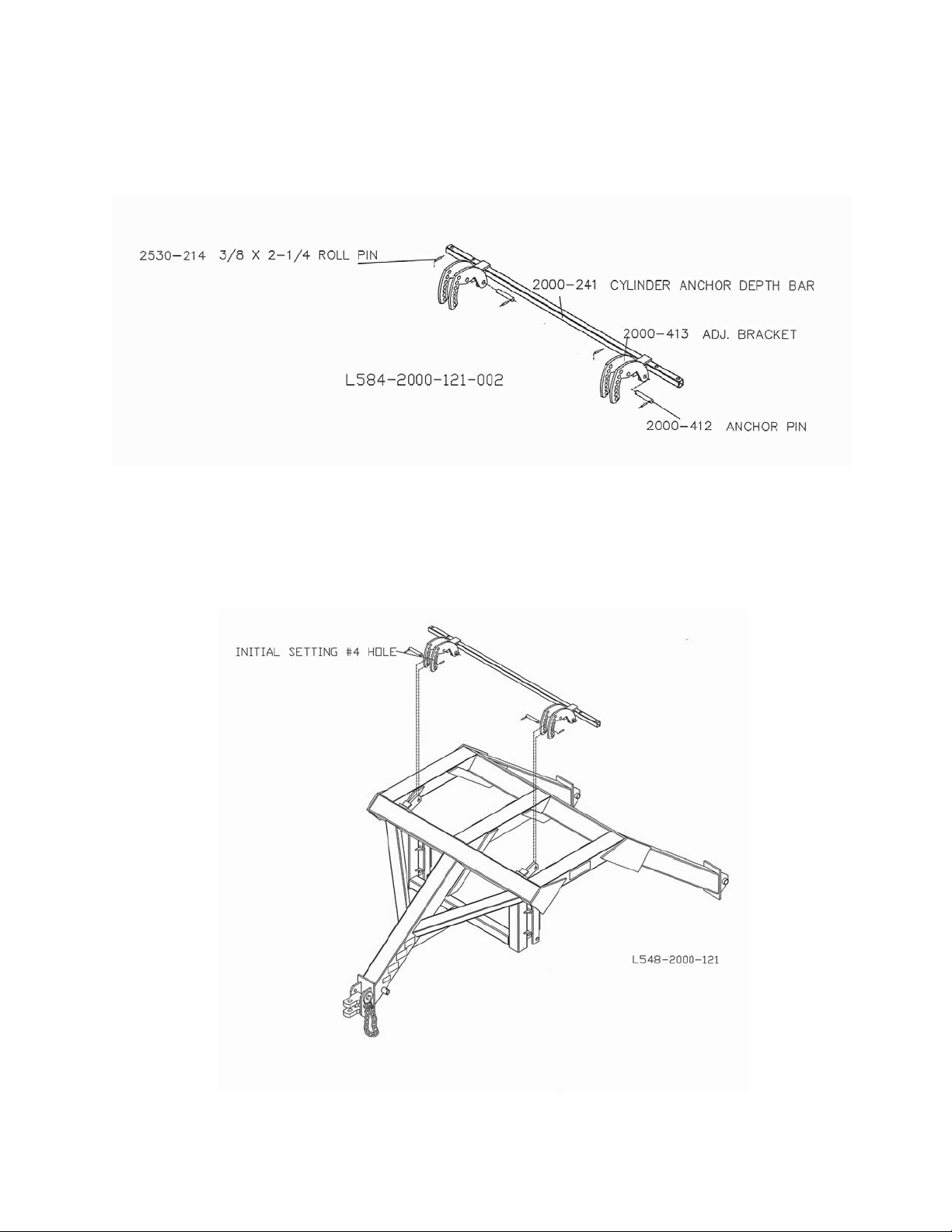
Step 6. Assemble the depth adjustment hardware.
Step 7. Install the depth adjustment bar to the Bridge Hitch.
9
Page 10

ASSEMBLY INSTRUCTIONS
Step 8. Clamp the depth adjustment to the toolbar. Torque to 300 ft/lbs.
Step 9. Attach the 4” X 12” hydraulic cylinders to the depth adjustment brackets.
10
Page 11

ASSEMBLY INSTRUCTIONS
Step 10. Install cylinder stops: 4 X 12 cylinder, toolbar lift.
IMPORTANT: Install 5”
of 2000-507 cylinder stop kit for 1-1/2” rod.
11
Page 12

ASSEMBLY INSTRUCTIONS
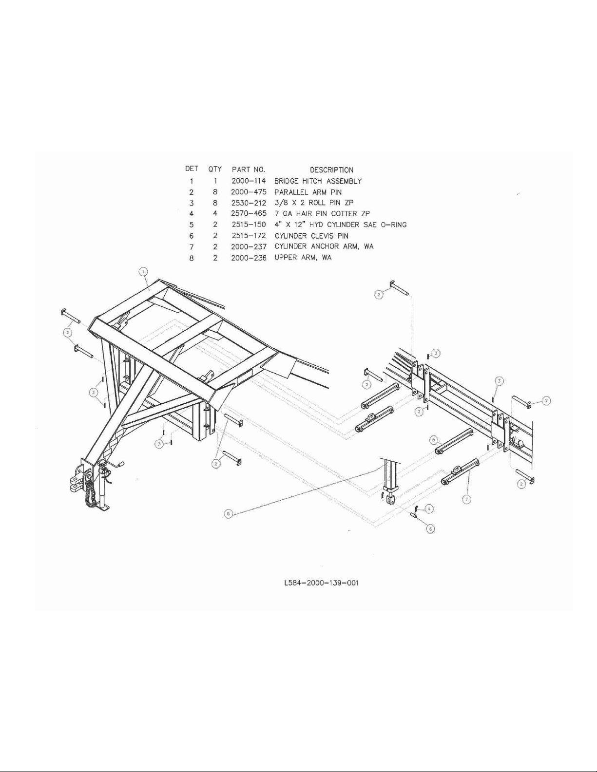
Step 11. Attach the parallel arms to the Bridge Hitch.
12
Page 13

ASSEMBLY INSTRUCTIONS
Step 12. Attach the toolbar frame to the parallel arms using the (4) pins and 3/8” X 2” roll pins.
13
Page 14

ASSEMBLY INSTRUCTIONS
Step 13. Attach the hydraulic cylinder and hardware to the toolbar assembly.
14
Page 15

Step 13. Continued
ASSEMBLY INSTRUCTIONS
15
Page 16

ASSEMBLY INSTRUCTIONS
Step 14. Install cylinder stops, 2000-511 (2” cylinder rod) to limit the toolbar wing folding.
16
Page 17

ASSEMBLY INSTRUCTIONS
Step 15. 2000-509 Cylinder Stop; Cut off length to 13” for 41’ Toolbar.
2000-509 “MODIFIED” FOR 41’ TOOLBAR
17
Page 18

ASSEMBLY INSTRUCTIONS
Step 16. Install the cylinder stops on the wing fold cylinders.
18
Page 19

Step 17.
ASSEMBLY INSTRUCTIONS
Install the wing fold stops to the toolbar. Do not fully tighten, will need to be adjusted later.
19
Page 20

Hydraulic Hook Up
1
serious personal injury. Fluid escaping from a small hole can be almost invisible. Use a piece of
cardboard or wood rather than hands to search for suspected leaks. Failure to heed may result in
personal injury or death.
The Yetter All Steer Plus ™ Fertilizer Toolbar requires two remote hydraulic valves on the tractor for proper
operation. Before operating in the field, perform the following steps.
DANGER: Inspect and replace worn or frayed hydraulic hose. Keep all connections tight,
escaping hydraulic fluid under pressure can have sufficient force to penetrate the skin and cause
1. Connect the All Steer Plus ™ Fertilizer Toolbar to the tractor drawbar before operating the cart hydraulic
system. Check the tractor hydraulic system fluid level. Filling all four cylinders with fluid will require
approximately 3-4 gallons. DO NOT operate tractor hydraulics when fluid level is too low.
2. Connect the hoses from the All Steer Plus ™ Fertilizer Toolbar to the tractor. The hydraulic hoses are
provided with the adapter attached. Use ¾-16” standard thread quick coupler tips.
3. Hold hydraulic lever in extend position for 15 seconds after cylinders are fully extended to purge air from
the system.
4. Recheck tractor fluid level and refill if necessary.
5. Cycle cylinders back and forth a couple of times to see that they operate together. Hold the lever in the
extended position a few seconds after each cycle for additional air purging.
NOTES:
20
Page 21

ASSEMBLY INSTRUCTIONS
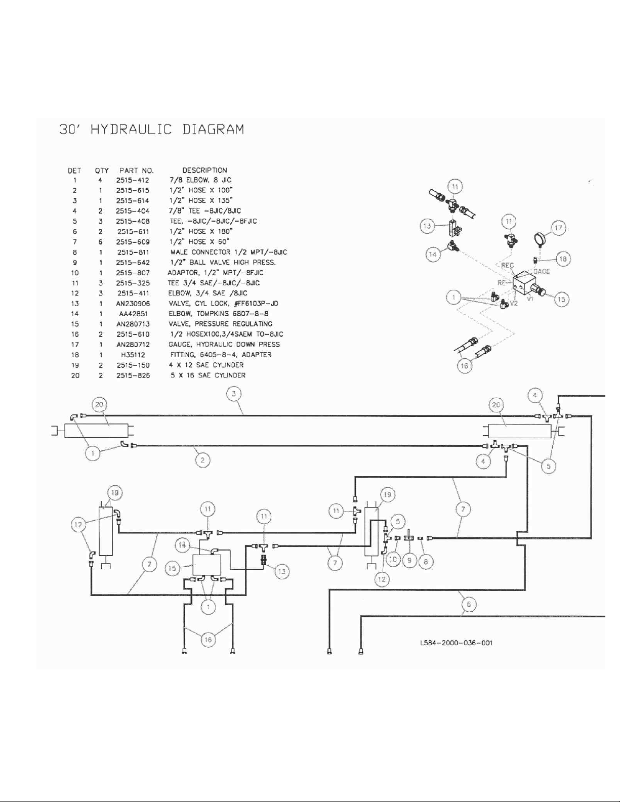
Step 18. Install the hydraulic hoses, fitting, and valves.
21
Page 22

Step 18. Continued
ASSEMBLY INSTRUCTIONS
22
Page 23

Step 19.
ASSEMBLY INSTRUCTIONS
Attach the valve bracket to the Bridge Hitch. Attach the valve to the bracket.
23
Page 24

ASSEMBLY INSTRUCTIONS
Step 20. Measure the toolbar to find the centerline. Mark the toolbar for clamp plate locations.
Note: It is very important that the clamp plates are tightened square to the toolbar. Attach the clamp kits to the
toolbar.
Step 21. Install the roll pin to the shank. Insert the locking collar into the coulter swivel casting. From the
bottom, fit the shank into the coulter swivel/collar assembly. Allow the coulter to swivel, turn the shank so that the
roll pin does not
100 ft/lb. maximum.
engage the notch in the casting. Install and tighten the set screw into the locking collar, torque
24
Page 25

ASSEMBLY INSTRUCTIONS
Step 22. Install the shank coulter assembly to the clamp kit, secure with the cotter pin and set screws. Adjust
the shank so that the cotter pin is down against the upper shank clamp casting. Tighten the set screws, torque
100 ft./lb. maximum.
25
Page 26

OPERATION
1
IMPORTANT: Do not operate the coulter depth so deep that the coulter hubs are in the soil, this will
cause premature bearing failure.
Yetter Model 2000 All Steer Plus™ Fertilizer Toolbar coulters are designed for fertilizer
placement 3” to 5” deep and to be operated 6-10 mph.
WARNING:
or implement. Failure to heed may result in personal injury or death.
Do not allow children to operate this equipment. Do not allow riders on the tractor
• During assembly, the coulters should be set up to swivel. This reduces the side load on the coulter during
operation.
• Set/mount coulter blades to run perpendicular to the soil. Operation depth and blade wear can be
affected if the shank is mounted crooked or if the toolbar is not level side to side.
• After a few hours of use, check all bolts for tightness and proper torque.
• After a day of use (10-12 hours) check coulter hubs for loose bearings. There should be no endplay in
the hub bearings allowing the blade to wobble. If necessary, remove hubcap and cotter pin and adjust
the slotted nut to remove wobble. Recommended torque of 15 ft lbs. If the wobble or looseness cannot
be corrected, the bearings, cups and seals will need to be replaced.
DO NOT USE WORN OR DAMAGED PARTS.
IMPORTANT: For proper operation, the All Steer Plus™ Fertilizer Toolbar frame must operate
level.
• Level the toolbar frame so that the coulter blades are the same depth front to back and side to side.
In hard no-till conditions the desired operating depth may not be possible. Tighten spring nut might be necessary,
to maintain tillage depth.
Drawbar Height
The Yetter 2000 Series All Steer Plus ™ Fertilizer Toolbar is designed to operate on tractors with drawbar heights
from 18” to 22” from the ground to the top of the drawbar. On certain tractors the drawbar can be turned over to
obtain the correct height. Proper operation of the equipment requires that the frame is level: front to rear as well
as side to side.
26
Page 27

OPERATION
Hydraulic Hook Up
1
serious personal injury. Fluid escaping from a small hole can be almost invisible. Use a piece of
cardboard or wood rather than hands to search for suspected leaks. Failure to heed may result in
personal injury or death.
The Yetter 2000 Series All Steer Plus ™ Fertilizer Toolbar requires two remote hydraulic valves on the tractor
for proper operation. Before operating in the field, perform the following steps.
DANGER: Inspect and replace worn or frayed hydraulic hose. Keep all connections tight,
escaping hydraulic fluid under pressure can have sufficient force to penetrate the skin and cause
1. Connect the All Steer Plus ™ Fertilizer Toolbar to the tractor drawbar before operating the cart
hydraulic system. Check the tractor hydraulic system fluid level. Filling all four cylinders with fluid
will require approximately 3-4 gallons. DO NOT operate tractor hydraulics when fluid level is too
low.
2. Connect the hoses from the All Steer Plus ™ Fertilizer Toolbar to the tractor. The hydraulic
hoses are provided with the adapter attached. Use ¾-16” standard thread quick coupler tips.
3. Hold hydraulic lever in extend position for 15 seconds after cylinders are fully extended to purge
air from the system.
4. Recheck tractor fluid level and refill if necessary.
5 Cycle cylinders back and forth a couple of times to see that they operate together. Hold the lever
in the extended position a few seconds after each cycle for additional air purging.
NOTES:
27
Page 28

OPERATION
PREPARING All Steer Plus ™ Fertilizer Toolbar 30’ For Transport
STEP 1. Remove wing flex cylinder stops from the 5” X 16” fold cylinders, place in storage location.
STEP 2. Fully raise toolbar against 4” X 12” lift cylinder stops.
STEP 3. Fold toolbar
STEP 4. Close transport valve
STEP 5. Close lift cylinder valve
28
Page 29

OPERATION
PREPARING All Steer Plus ™ Fertilizer Toolbar 30’ For Field
STEP 1. Unfold toolbar
STEP 2. Install wing flex cylinder stops onto 5 X 16 hydraulic fold cylinders
STEP 3. Open transport valve
STEP 4. Open lift cylinder valve
STEP 5. Lower toolbar to engage coulter blades into the soil
29
Page 30

OPERATION
All Steer Plus ™ Fertilizer Toolbar 41’
PREPARING FOR TRANSPORT
Step 1. Remove wing flex cylinder stops from the 5” X 16” fold cylinders, place in the storage location.
Step 2. Open valves wing fold cylinders.
Step 3. Fully raise toolbar against 4” X 12” lift cylinder stops.
Step 4. Close Transport valve.
Step 5. Close valve lift cylinder.
30
Page 31

OPERATION
All Steer Plus ™ Fertilizer Toolbar 41’
PREPARING FOR FIELD
Step 1. Unfold toolbar
Step 2. Install wing flex cylinder stops onto 5” X 16” fold cylinders.
Step 3. Open transport valve.
Step 4. Open valve – lift cylinder
Step 5. Close valves – wing fold cylinder
Step 6. Lower toolbar to engage coulter blades into the soil
31
Page 32

OPERATION
COULTER BLADE DEPTH ADJUSTMENT
To change to the operating depth of the coulter blades, the adjustment is to be pinned in one of seven holes.
The top hole is for deep placement and the bottom hole is for shallow placement. Initially, use the 4
then adjust the bracket according to field conditions.
IMPORTANT: To prevent damage to the machine, when the adjustment bracket is moved to change blade
depth, the cylinder stops must
be changed also.
th
hole,
32
Page 33

MAINTENANCE
WARNING: Never clean, lubricate or adjust a machine that is in motion. Failure to heed may
result in serious personal injury or death.
COULTER BLADE WEAR
Blade wear can affect performance in loose trash conditions. Depth control and plugging problems can result. It
may be necessary to replace blades.
WARNING: If required to service unit in raised position, be sure to close the hydraulic valves.
Place a safety stand under the toolbar. Failure to heed may result in serious personal injury or
death.
DANGER: Inspect and replace worn or frayed hydraulic hose. Keep all connections tight.
Escaping hydraulic fluid under pressure can have sufficient force to penetrate the skin and cause
serious personal injury. Fluid escaping from a small hole can be almost invisible. Use a piece of
cardboard or wood rather than the hands to search for suspected leaks. Failure to heed may result in
serious personal injury or death.
LUBRICATION
WARNING: Never clean, lubricate or adjust a machine that is in motion. Failure to heed may
result in serious personal injury or death.
Lubricate with general-purpose grease
•
To ensure longevity and reliability of the All Steer Plus ™ Fertilizer Toolbar, each coulter assembly
has (2) grease fittings. Grease the pivots weekly. Grease the hub four times per season. Repack the
hubs once per season.
• There is a grease fitting on each end of the upper and lower parallel arms. Grease every 10 hours.
BEARING ADJUSTMENT:
1. Raise the toolbar until the blade is clear of the ground. Place a safety stand under the toolbar. Remove
the hubcap, cotter pin, slotted nut and washer from the hub assembly. Remove the blade from the hub
assembly.
2. Remove bearing cones and seals from hub.
3. Wash the old grease from the hub, bearing cups, spindle spacers, seals and bearing cones. Inspect the
condition of the bearing cups, cones and seals. Replace if necessary.
4. Apply #2 multi-purpose lithium grease on each bearing. Make sure the space around each roller is filled.
Lubricate the bearing cups.
5. Position the bearing in the cup and install the seal. Lubricate the seal lips and proceed with re-assembly
of the removed parts including the blade. Blade bolt torque is 90 to 96 ft. lbs.
Tighten the slotted nut to 15 ft. lbs. or until a definite drag is felt when the hub is turned by hand. Tighten the nut
one-slot position to line up the cotter pin hole with a slot. Secure the nut with a new cotter pin, replace hubcap.
33
Page 34

PARTS INDENTIFICATION
34
Page 35

PARTS INDENTIFICATION
35
Page 36

PARTS INDENTIFICATION
36
Page 37

PARTS INDENTIFICATION
37
Page 38
PARTS INDENTIFICATION
38
Page 39

PARTS INDENTIFICATION
39
Page 40

PARTS INDENTIFICATION
40
Page 41

PARTS INDENTIFICATION
41
Page 42

PARTS INDENTIFICATION
42
Page 43
PARTS INDENTIFICATION
43
Page 44

PARTS INDENTIFICATION
44
Page 45

PARTS INDENTIFICATION
45
Page 46

PARTS INDENTIFICATION
46
Page 47

PARTS INDENTIFICATION
47
Page 48

PARTS INDENTIFICATION
48
Page 49

PARTS INDENTIFICATION
2000-035 GAUGE WHEEL ASSY
49
Page 50

NOTES:
50
Page 51

TROUBLESHOOTING
Problem Cause Solution
Setting coulter depth equally Frame not set correctly Ensure that in operation
the frame is level.
Blade not penetrating Insufficient coulter spring Tighten coulter spring
pressure. locknut down 1” further.
Coulter incorrectly installed Adjust height of coulter by
sliding shank down at the
clamp kit.
Spring not deflecting Excessive spring pressure Back off coulter spring
locknut.
Blade not rotating Bearings too tight See maintenance section
for proper bearing adjustment
51
Page 52

Our name
Is getting known
Just a few years ago, Yetter products were sold primarily to the
Midwest only. Then we embarked on a program of expansion and
moved into the East, the South, the West and now north into
Canada. We’re even getting orders from as far away as
Australia and Africa.
So, when you buy Yetter products . . .you’re buying a name that’s
recognized. A name that’s known and respected. A name that’s become
a part of American agriculture and has become synonymous with quality
and satisfaction in the field of conservation tillage.
Thank you.
YETTER MANUFACTURING CO.
Colchester, IL 62326-0358 • 309/776-4111
Toll Free 800/447-5777
Fax 309/776-3222
Website: WWW.YETTERCO.COM
E-MAIL: INFO@YETTERCO.COM
2565-737 • 10/08
52
 Loading...