


BULK SEED HANDLING EQUIPMENT
PARTS & SET-UP MANUAL
2565-463_REV_C 09/2012
YETTER MANUFACTURING CO.
FOUNDED 1930
Colchester, IL 62326-0358
Toll free: 800/447-5777
309/776-3222 (Fax)
Website: www.yetterco.com
E-mail: info@yetterco.com
1300 SERIES

FOREWORD
You’ve just joined an exclusive but rapidly
growing club.
For our part, we want to welcome you to the
group and thank you for buying a Yetter product.
We hope your new Yetter products will help you
achieve both goals-increase your productivity and
increase your efficiency so that you may generate
more profit.
This operator’s manual has been designed into
four major sections: Foreword, Safety
Precautions, Installation Instructions and Parts
Breakdown.
This SAFETY ALERT SYMBOL
indicates important safety messages in
the manual. When you see this
symbol, be alert to the possibility of
PERSONAL INJURY and carefully
read the message that follows.
The word NOTE is used to convey information
that is out of context with the manual text. It
contains special information such as
specifications, techniques and reference
information of a supplementary nature.
The word IMPORTANT is used in the text when
immediate damage will occur to the machine due
to improper technique or operation. Important will
apply to the same information as specified by
note only of an immediate and urgent nature.
It is the responsibility of the user to read the
operator’s manual and comply with the safe and
correct operating procedure and to lubricate and
maintain the product according to the
maintenance schedule in the operator’s manual.
The user is responsible for inspecting his
machine and for having parts repaired or
replaced when continued use of the product
would cause damage or excessive wear to the
other parts.
It is the user’s responsibility to deliver his
machine to the Yetter dealer who sold him the
product for service or replacement of defective
parts, which are covered by the warranty policy.
If you are unable to understand or follow the
instructions provided in this publication, consult
your local Yetter dealer or contact:
YETTER MANUFACTURING CO.
309/776-4111
800/447-5777
309/776-3222 (FAX)
Website: www.yetterco.com
E-mail: info@yetterco.com
WARRANTY
Yetter Manufacturing warrants all products manufactured and sold by it against defects in material. This
warranty being expressly limited to replacement at the factory of such parts or products as shall appear to
be defective after inspection. This warranty does not obligate the Company to bear cost of labor in
replacement of parts. It is the policy of the Company to make improvements without incurring obligations to
add them to any unit already sold. No warranty is made or authorized to be made, other than herein set
forth. This warranty is in effect for one year after purchase.
Dealer ___________________________________________________
Yetter Manufacturing warrants its own products only and cannot be responsible for damages to
equipment on which mounted.
2

SAFETY PRECAUTIONS
You can make your farm a safer place to live and work if you observe the safety precautions given. Study these
precautions carefully and insist those working with you and for you follow the precautions.
Finally, remember this an accident is usually caused by someone’s carelessness, neglect or oversight.
A brief description of signal words that may be used in this manual:
CAUTION: Used as a general reminder of good safety practices or to direct attention to unsafe practices.
WARNING: Denotes a specific potential hazard.
DANGER: Denotes the most serious specific potential hazard.
CAUTION
Consult your implement and tractor operator’s manual for correct and safe operating practices. Be aware of towed
implement width and allow safe clearance.
CAUTION: SAFETY SIGNS
Safety decals are placed on the implement to alert the operator and others to the risk of personal injury or unsafe
operation during normal operations and servicing.
1. The safety decals must be kept clean and in good condition to ensure that they are legible.
2. Safety decals must be replaced if they are missing or illegible.
3. When components are replaced during repair or servicing, check that the new components include the necessary
safety signs.
4. Replacement safety decals may be obtained from your local dealer.
WARNING
Read these instructions carefully to acquaint yourself with the Seed Handling Equipment. Working with unfamiliar
equipment can lead to accidents.
Safety shields must always be in place during operation.
Never park the equipment on a steep incline or leave the equipment running unattended.
Never clean, lubricate or adjust a machine that is in motion. Always remove spark plug wire before performing service.
Always replace safety shields after servicing.
Always check that straps are secure.
Be sure trolley is pinned and the chute is down in transport.
Make sure latches are in pinned position when moving equipment.
Do not allow children to operate this equipment.
Do not allow riders on the equipment, trailer and/or pick-up.
Use speed and caution dictated by the terrain being traversed. Do not operate on any slope steep enough to cause
tipping or loss of control.
Be sure all personnel are clear of the immediate area before operating.
Read and understand the operator’s manual and require all other persons who will operate the equipment to do the
same.
If operating on public roadways, where legal, be certain all lighting is operating properly and observe all traffic laws.
Beware of increased stopping distances and control effort when operating with implements attached.
Be familiar with all controls and be prepared to stop engine and equipment quickly in an emergency.
If seed or seed treatment is dusty or dirty, wear full-face respirator.
FAILURE TO HEED MAY RESULT IN PERSONAL INJURY OR DEATH.
3

TABLE OF CONTENTS
PAGE
FORWARD/WARRANTY……………………………………………………….2
SAFETY INFORMATION……….………………………………………..……..3
TABLE OF CONTENTS……..….………………………………………..……..4
GENERAL INFORMATION/BOLT TORQUE…………………………....…...5
ASSEMBLY INSTRUCTIONS
1300-183 – POWER UNIT…………………………………………………...6
1300-132 – FRAME – SEED TRAIN……………………………………..7-8
1300-133 – TROLLEY/AIRLOCK/SEED CHUTE.………………….....9-15
1300-131 - FRAME CONVECTION KIT – SEED TRAIN..…………..16-18
1300-156 - SEED HOSE/POWER CABLE…..………………………..14-15
1300-413 - WIRELESS REMOTE/RECEIVER SJ II……………………..19
OPERATING INSTRUCTIONS…………………………………………………20
MAINTENANCE
USE/PREPARATION………………………………………………………..21
STORAGE…………………………………………………………….………21
PART IDENTIFICATION
1300-183………………………………………………………………………22-29
1300-132…………………………………………………………………………..30
1300-133…………………………………………………………………………..31
1300-131…………………………………………………………………………..32
1300-156…………………………………………………………………………..33
1300-150…………………………………………………………………………..34
1300-146…………………………………………………………………………..35
7100-101…………………………………………………………………………..36
7100-112…………………………………………………………………………..37
7100-102…………………………………………………………………………..38
1300-144…………………………………………………………………………..39
1300-166…………………………………………………………………………..40
1300-161…………………………………………………………………………..41
1300-159………………………………………………………………………42-43
1300-151…………………………………………………………………………..44
1300-119…………………………………………………………………………..45
1300-130…………………………………………………………………………..46
1300-147…………………………………………………………………………..47
1300-157…………………………………………………………………………..48
1300-160/165……………………………………………………………………..49
POWER UNIT WIRING DIAGRAM…………………………………………….50
TROUBLESHOOTING……………….………………………………………….51
4

GENERAL INFORMATION
BOLT TORQUE
READ THESE INSTRUCTIONS FIRST:
1. Improperly tightened bolts will result in damage, breakage, expense, and down time.
2. Always replace bolts with the specified grade and type.
3. Torque properly before first use of the machine and every 2-4 hours of use until you are sure bolts
are staying tight.
4. The chart below is a guide for proper torque. Use it unless a specified torque is called out
elsewhere in the manual.
5. Torque is the force you apply to the wrench handle or the cheater bar, times the length of the
handle or bar.
6. Use a torque wrench whenever possible.
The following table shows torque in ft. lbs.
Lubricate all bearings and moving parts as assembled and make certain that they work freely.
5

GENERAL INFORMATION
POWER UNIT SET UP
NOTE: Gasoline, oil and a 12-Volt battery (Group 58 or 26-70) will be required before the unit can
be operated.
DO NOT START ENGINE OR USE BLOWER BEFORE FILLING WITH PROPER
LUBRICANTS. ENGINE HAS AN OIL LEVEL SENSOR; OIL LEVEL MUST BE FULL ON
DIPSTICK. DO NOT OVERFILL!!
6

ASSEMBLY INSTRUCTIONS
1300-132 SEED TRAIN FRAME ASSEMBLY
Step 1.
stands to the frame using ½” x 1 ½” bolts and lock nuts. Fasten the other two stands and hose hooks using
the ½” x 2” bolts and lock nuts. Do no fully tighten the bolts.
Attach the 4) 1300-249 stands and 2) 1300-478 hose hooks to the 1300-225 frame. Fasten two
Step 2.
½” lock nuts.
Attach the 2) 1300-229 leg brace to the 1300-249 stand bracket using 8) ½” x 2” x 3” u-bolts and
Step 3.
Tighten all bolts in steps 1 and 2 to the proper torque ratings of 85 ft. lbs.
7

ASSEMBLY INSTRUCTIONS
SEED TRAIN FRAME (CONT.)
Step 4.
and 1300-460 left hand roller track to the frame in the second hole from the top using 4) ½” x 1 ½” carriage
bolts, 2) ½” x 3” bolts 2) 1300-493 2” bushings and ½” lock nuts.
Step 5.
the top using 2) 3/8” x 1” bolts and lock nuts.
Remove the roller tracks from shipping position and attach the 1300-459 right hand roller track
Attach the 6) clamp angles (1300-463) to the 6) latch brackets (1300-230) in the fourth hole from
Step 6.
cotter.
8
Attach the 6) latch assemblies to the frame using ½” x 4” bolts, lock nuts, lock pin and hairpin

ASSEMBLY INSTRUCTIONS
SEED TRAIN TROLLEY 1300-133
Step 1.
3/8” x 3” bolts, 2) 3/8” x 1 ¼” bolts and 3/8” lock nuts.
Elevate the power unit and attach the 2) 1300-573 motor mount strap to the power unit using 2)
Step 2.
washers and hex nuts.
Attach the 2) 1300-236 motor trolley brackets to the motor mounts using 4) 3/8” x 1 ¼” bolts, lock
9

ASSEMBLY INSTRUCTIONS
SEED TRAIN TROLLEY 1300-133 (CONT.)
Step 3.
bolts, bearing, ¾” spacers, 2) 5/8” flat washers, 2) 1300-487 trolley guides and lock nuts.
NOTE: DO NOT OVER-TIGHTEN THE 5/8” LOCK NUT, THE BEARING MUST TURN FREELY.
Attach the 1300-235 trolley roller frame to the motor trolley bracket using 4) 5/8” x 3” carriage
Step 4.
and 5/8” lock nuts to the front holes of the 1300-235 trolley roller frame. Note: Use the 5/8” flat washers as
needed to space the bearing and the trolley guide. The trolley roller frame needs to roll smoothly back and
forth on the track.
Attach the 2) 5/8” X 3” carriage bolts, 2) bearings, 5/8” flat washers, 2) 1300-487 trolley guides
10

SEED TRAIN TROLLEY 1300-133 (CONT.)
Step 5.
flat washers and 5/16” lock nuts.
Attach the Airlock/Motor assembly to the seed chute assembly using 8) 5/16” x 1 ½” bolts, 5/16”
Step 6.
1” bolts and ½” lock nuts.
Attach the Seed Chute/Airlock/Motor assembly to the 1300-235 trolley roller frame using 4) 1/2” x
ASSEMBLY INSTRUCTIONS
11

ASSEMBLY INSTRUCTIONS
SEED TRAIN TROLLEY 1300-133 (CONT.)
Step 7.
it with the 2 ¼” muffler clamp. Do Not Over Tighten the clamp, to avoid damaging the steel flex hose.
Attach the 1300-155 17” steel flex hose assembly to the airlock at the 2 ¼” steel pipe and secure
Step 8.
assembly, it is recommended that the hose barb end of the quick coupler can be lubricated with a non-oil
based product. Example: dish soap. Then slide a hose clamp on the other end of the 2” rubber hose and
install onto the airlock at the 2” steel pipe nipple.
Assemble the 2” rubber hose, 2” hose barb quick coupler and a hose clamp. HINT: to aid in the
12

ASSEMBLY INSTRUCTIONS
Step 9.
plastic cable tie to support the 2” rubber hose so that it does not drag or bind when the trolley is rolled on
the track.
Connect the 2” rubber hose quick coupler to the blower on the power unit. Next, use a 2515-552
Step 10.
with 2965-305 pins and hairpin cotter.
Next, set the power unit/trolley frame/airlock assembly onto the roller tracks and secure in place
Step 11.
nuts.
Attach the 2) angle trolley stops to the R.H. and L.H. roller tracks using 2) ½” x 1” bolts and lock
SEED TRAIN TROLLEY 1300-133 (CONT.)
13
ASSEMBLY INSTRUCTIONS
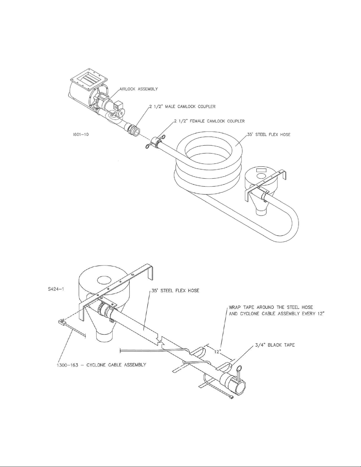
Step 12.
coupler. Secure the cam latches with the hairpin clips.
Attach the 35’ steel flex hose assembly to the airlock using the 2 ½” aluminum cam lock
SEED TRAIN TROLLEY 1300-133 (CONT.)
Step 13.
with ¾” black electrical tape at 12” increments.
14
Loosely coil the 1300-163 cyclone cable assembly around the 35’ steel flex hose and secure

ASSEMBLY INSTRUCTIONS
Step 14.
cuff into the top of the cyclone. Secure the vinyl hose to the steel flex hose using the 3) 2515-405 cable
ties.
Thread the 2515-712 L.H. threaded hose cuff onto the 1300-553 vinyl hose. Insert the hose
SEED TRAIN TROLLEY 1300-133 (CONT.)
Step 15.
the 5’ cable extension to the switch input plug of the silver module box on the power unit.
Connect the 1300-163-cyclone cable to the 1300-558 5’ control cable extension and connect
15

ASSEMBLY INSTRUCTIONS
When two or more frame assemblies are used together, the 1300-131-connection assembly must be used.
Step 1.
Set the frames front to back of each other and aligned.
SEED TRAIN FRAME CONNECTION KIT 1300-131
Step 2.
stands of the rear frame. Save the locknuts, they will be used in a later assembly.
Remove the ½” x 2” x 3” u-bolts from the back leg stands of the forward frame and front leg
16

ASSEMBLY INSTRUCTIONS
SEED TRAIN FRAME CONNECTION KIT 1300-131 (CONT.)
Step 3.
½” bolts and re-using the ½” locknuts used previously with the u-bolts. DO NOT TIGHTEN BOLTS.
Attach the 2) short leg braces 1300-224 to the leg stands and the long leg braces using 8) ½” x 3
Step 4.
bushings and ½” lock nuts, connect the frame assemblies. DO NOT TIGHTEN BOLTS.
Using the 4) ½” x 8” bolts, through the top two holes in the angle track bracket, 4) 6-19/64”
17
 Loading...