

Page 1

Systems One
2565-441_REV_D 02/2012
YETTER MANUFACTURING CO.
FOUNDED 1930
Colchester, IL 62326-0358
Toll free: 800/447-5777
309/776-3222 (Fax)
Website: www.yetterco.com
E-mail:
info@yetterco.com
A YETTER COMPANY
SEED JET II
1
Page 2

FOREWORD
You’ve just joined an exclusive but rapidly
growing club.
For our part, we want to welcome you to the
group and thank you for buying a Yetter
product.
We hope your new Seed Jet II will help you
achieve both increased productivity and
increased efficiency so that you may generate
more profit.
This operator’s manual has been designed
into four major sections: Foreword, Safety
Precautions, Installation Instructions and
Parts Breakdown.
This SAFETY ALERT SYMBOL
indicates important safety messages in
the manual. When you see this
symbol, be alert to the possibility of
PERSONAL INJURY and carefully read the
message that follows.
The word NOTE is used to convey information
that is out of context with the manual text. It
contains special information such as
specifications, techniques, reference
information of a supplementary nature.
The word IMPORTANT is used in the text
when immediate damage will occur to the
machine due to improper technique or
operation. Important will apply to the same
information as specified by note only of an
immediate and urgent nature.
It is the responsibility of the user to read the
operator’s manual and comply with the safe
and correct operating procedure and to
lubricate and maintain the product according
to the maintenance schedule in the operator’s
manual.
The user is responsible for inspecting his
machine and for having parts repaired or
replaced when continued use of the product
would cause damage or excessive wear to
the other parts.
It is the user’s responsibility to deliver his
machine to the Yetter dealer who sold him the
product for service or replacement of
defective parts, which are covered by the
warranty policy.
If you are unable to understand or
follow the instructions provided in this
publication, consult you local Yetter dealer or
contact: SYSTEMS ONE
309/776-4111
800/447-5777
309/776-3222 (FAX)
E-mail: info@yetterco.com
WARRANTY POLICY
Yetter Manufacturing warrants all products manufactured and sold by it against defect in material. This
warranty being expressly limited to replacement at the factory of such parts or products as shall appear to be
defective after inspection. This warranty does not obligate the Company to bear cost of labor in replacement
of parts. It is the policy of the company to make improvements without incurring obligations to add them to
any unit already sold. No warranty is made or authorized to be made other than herein set forth. This
warranty is in effect for 1 year after purchase.
Dealer ___________________________________
Yetter Manufacturing warrants its own products only and cannot be responsible for
damage to equipment on which mounted.
2
Page 3

TABLE OF CONTENTS
Cover Page…………………………………………………………………….. 1
Foreword……………………………………………………………………….. 2
Table of Contents……………………………………………………………… 3
Safety Information……………………………………………………………... 4
General Information…………………………………………………………… 5
Assembly Instructions
1300-183 Power Unit Assembly……….……………………………...6
1300-120 Hopper Assembly……………………………………….… 7
1300-124 Seed Jet II Hose Assembly………………………………8-9
Operation………………………………………………………………………..10
Maintenance…………………………………………………………………….11
Parts Identification
1300-121 Seed Jet II………………………………………………….12
1300-120 Hopper Assembly………………………………………….13
1300-119 Airlock Assembly…………………………………………..14
1300-183 Power Unit Assembly………………………………….15-22
1300-124 Seed Jet II Hose Assembly……………………………….23
1300-166 Cyclone Exhaust kit………………………………………..24
Cyclone Shutoff…………………………………………….24
1300-620 Remote Control (OPTIONAL)…………………………….25
1300-178 Cyclone Switch Pack………………………………………25
Trouble Shooting………………………………………………………………..26
3
Page 4

SAFETY PRECAUTIONS
You can make your farm a safer place to live and work if you observe the safety precautions given. Study these precautions
carefully and insist those working with you and for you follow the precautions.
Finally, remember this an accident is usually caused by someone’s carelessness, neglect or oversight.
A brief description of signal words that may be used in this manual:
CAUTION: Used as a general reminder of good safety practices or to direct attention to unsafe practices.
WARNING: Denotes a specific potential hazard.
DANGER: Denotes the most serious specific potential hazard.
CAUTION
Consult your implement and tractor operator’s manual for correct and safe operating practices. Be aware of towed
implement width and allow safe clearance.
CAUTION: SAFETY SIGNS
Safety decals are placed on the implement to alert the operator and others to the risk of personal injury or unsafe
operation during normal operations and servicing.
1. The safety decals must be kept clean and in good condition to ensure that they are legible.
2. Safety decals must be replaced if they are missing or illegible.
3. When components are replaced during repair or servicing, check that the new components include the necessary
safety signs.
4. Replacement safety decals may be obtained from your local dealer.
WARNING
Read these instructions carefully to acquaint yourself with the Seed Jet II. Working with unfamiliar equipment can lead to
accidents.
Safety shields must always be in place during operation.
Never park the gravity wagon on a steep incline or leave the equipment running unattended.
Never clean, lubricate or adjust a machine that is in motion. Always remove spark plug wire before performing service.
Always replace safety shields after servicing.
If machine must be serviced in the raised position, jack or block it up to prevent it from accidentally falling and injuring
someone.
Be sure the park brake is set before operating.
Do not allow children to operate this equipment.
Do not allow riders on the wagon or pickup.
Use speeds and caution dictated by the terrain being traversed. Do not operate on any slope steep enough to cause
tipping or loss of control.
Be sure all personnel are clear of the immediate area before operating.
Read and understand the operator’s manual and require all other persons who will operate the equipment to do the
same.
If operating on public roadways, where legal, be certain all lighting is operating properly and observe all traffic laws.
Attach a slow moving vehicle emblem to the rear of the trailing implement.
Beware of increased stopping distances and control effort when operating with implements attached.
Be familiar with all controls and be prepared to stop engine and equipment quickly in an emergency.
If seed or seed treatment is dusty or dirty, wear a full-face respirator.
4
Page 5

FAILURE TO HEED MAY RESULT IN PERSONAL INJURY OR DEATH.
GENERAL INFORMATION
SHIPMENT CHECKLIST
Your Seed Jet II is shipped as a complete unit in one container. Please check that the following
items are received in the container:
Power Unit Assembly
Hopper Assembly
Bolt Bag, Seed Jet II
Seed Jet II Hose Assembly
Pair of Hopper Brackets
Cyclone Cable Assembly
Cyclone Exhaust Kit
15' of Rubber Flex Hose
NOTE: Gasoline, oil and a 12-Volt battery (Group 58 or 26-70) will be required before the unit
can be operated.
DO NOT START ENGINE OR USE BLOWER BEFORE FILLING WITH PROPER
LUBRICANTS. ENGINE HAS AN OIL LEVEL SENSOR; OIL LEVEL MUST BE FULL ON
DIPSTICK. DO NOT OVERFILL!!
5
Page 6

ASSEMBLY INSTRUCTIONS
POWER UNIT SET UP
1. Add oil to blower gear case. DO NOT OVERFILL. 8 oz., 80W-140 gear oil (ISO220, 5EP, GL-5
service grade). Lubricate the bearings using Shell Darina EP NLG grade 2 grease.
2. Fill crankcase of engine with oil. (High quality SAE 30 weight, SE, SF or SG service grade)
3. Fill gasoline tank with clean, fresh lead free gasoline (85 octane).
NOTE: Engine Manufacturer does not recommend the use of gasoline, which
contains alcohol such as gasohol. If gasoline with alcohol is used, it must not
contain more than 10% Ethanol and MUST be removed from the engine during
storage. DO NOT use gasoline-containing methanol.
4. Install and clamp securely a 12-volt battery, Group 58 or 26-70.
5. Check that all electrical connections are tight.
6. Check tension of drive belt.
7. Ensure that all safety shields are in place.
NOTE: For questions concerning warranty on the engine or blower contact the
corresponding manufacturer or the local service/retail outlet.
6
Page 7
ASSEMBLY INSTRUCTIONS
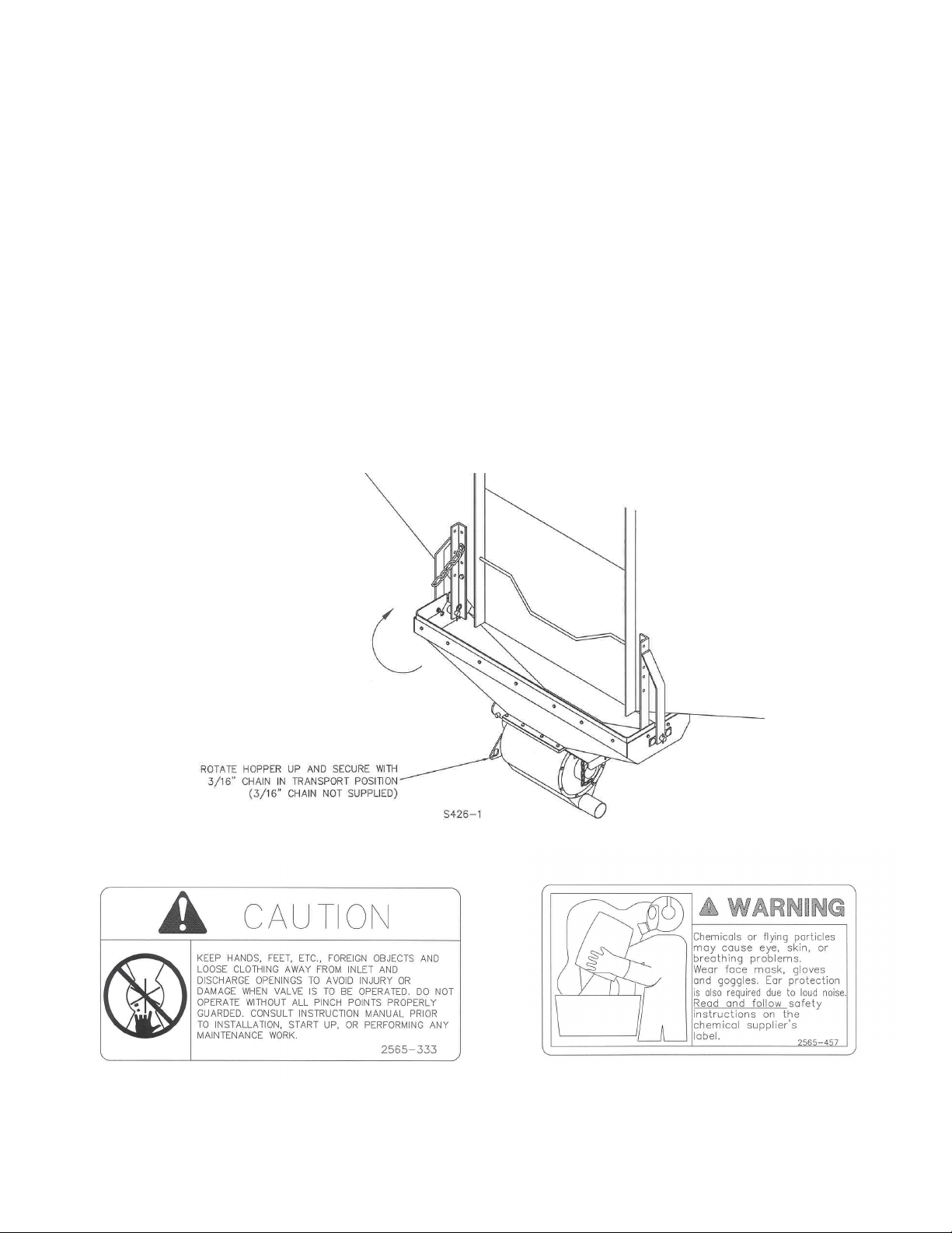
HOPPER UNIT SET UP
With the assistance of another person and/or lifting equipment, position the hopper assembly next to
the discharge slide door of your gravity wagon. The hopper should be level once attached.
The brackets supplied are of a universal type and it may be necessary to drill extra holes in the
frame of your wagon to attach these parts. The long pins and spacers provided should
accommodate most sizes of wagons. Install the 3/16” x 1 ¼” roll pin onto the hopper pins before
attaching the hopper to the brackets.
*CAUTION: Ground clearance of wagon is reduced when hopper unit is attached,
before transporting, rotate the hopper assembly upward and secure with
3/16 chain. Negotiate obstacles and uneven terrain carefully.
7
Page 8
ASSEMBLY INSTRUCTIONS
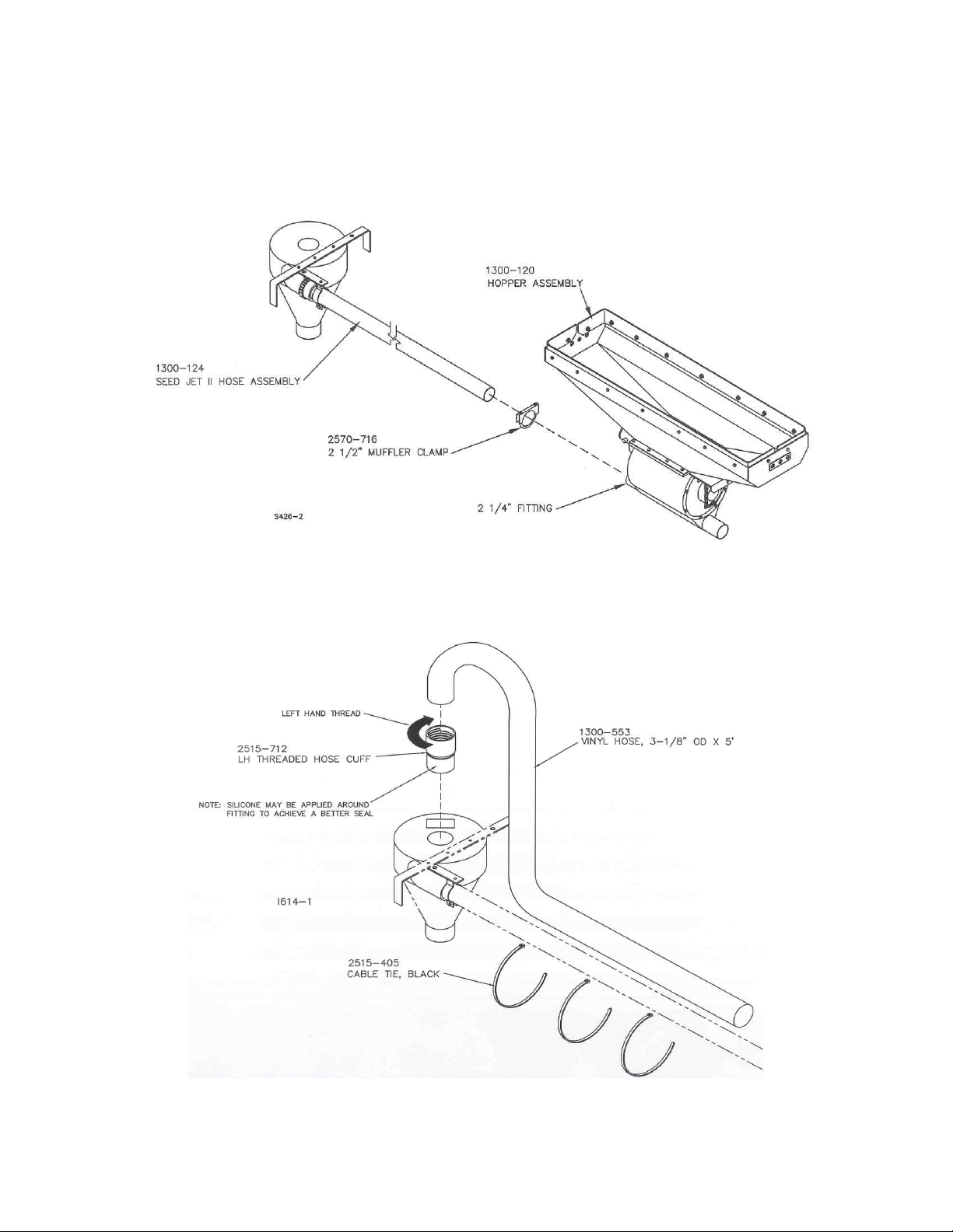
35’ SEED HOSE ASSEMBLY
STEP 1. Attach the 1300-124 seed hose assembly to the 2 1/4” airlock fitting and secure with the 2570-
716 muffler style clamp. DO NOT OVER TIGHTEN THE CLAMP.
STEP 2. Attach the 1300-166 cyclone exhaust kit to the seed cyclone. Left hand thread the 2515-712 hose
cuff onto the 1300-553 3 1/8” OD vinyl hose. Then insert the hose and cuff assembly into the top of the
cyclone. Using plastic tie straps, tie the vinyl hose to the stainless steel seed hose using the (3) 2515-405
black cable ties.
8
Page 9
ASSEMBLY INSTRUCTIONS
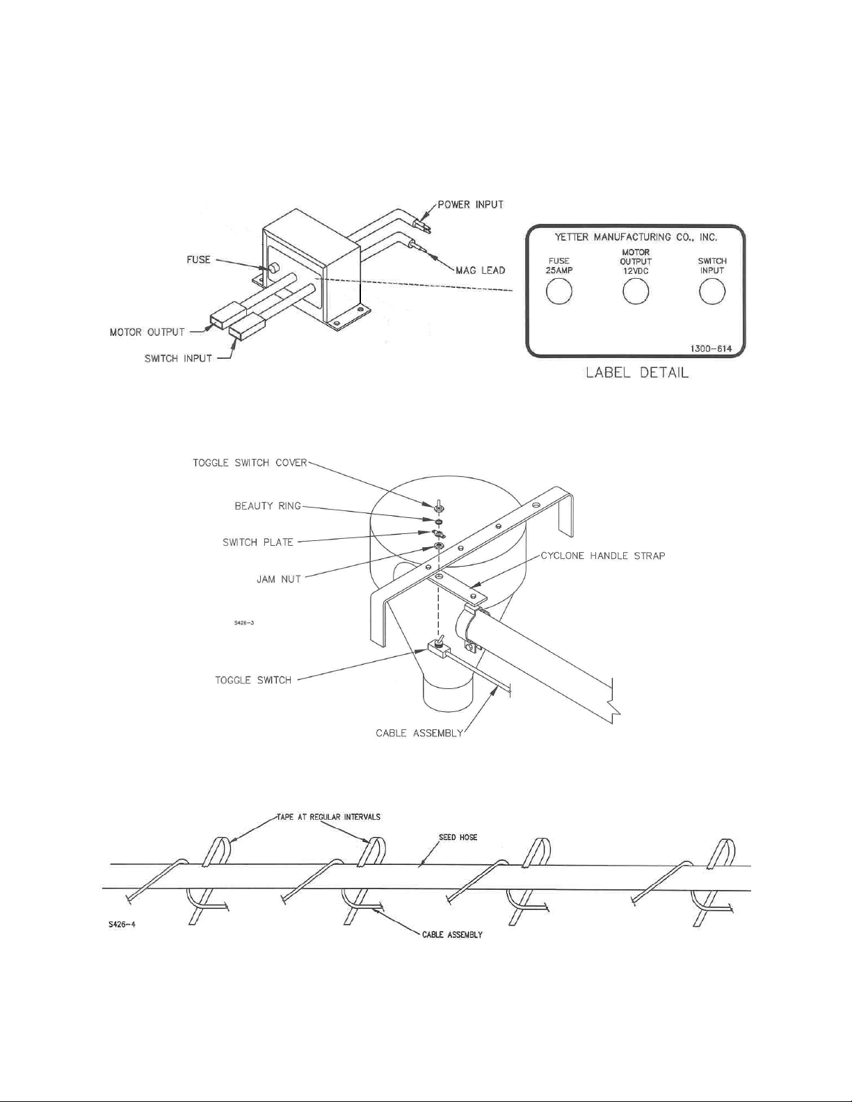
STEP 3. Attach the 1300-163 cable assembly to the 1300-124 seed hose assembly. Connect the 1300-
163 cable to the power unit’s module at the plug connector labeled “switch input”. Inspect the plug
connector for dirt, debris or bent pins; clean and repair the connectors if necessary.
STEP 3. CONTINUED….Coil the cable assembly around the seed hose. Install the toggle switch to the
cyclone handle and secure with the jam nut.
STEP 4. Tape the seed hose assembly and the cable assembly together at regular intervals to prevent
snagging and damaging of the cable assembly.
9
Page 10

SYSTEM HOOK UP AND USE
These instructions are to describe the typical set up of the Seed Jet II on a gravity flow wagon towed
by a pickup truck.
1. Place power unit assembly in pickup bed and hitch truck to gravity wagon.
2. Assemble the rubber flex hose from the blower to inlet side of airlock using the quick coupler
half provided and four hose clamps along with sufficient length of hose. Less hose will be
required if the tailgate is lowered. Attach the hose, where required, to the frame of the wagon
with cable ties (not supplied) to prevent interference with any moving parts of the wagon such as
steering mechanisms or tires.
3. Run the duplex wire along a similar route to the hose and secure where necessary to prevent
interference with any moving parts of the wagon such as steering mechanisms or tires.
4. After uncoupling the quick coupler at the blower and weather pack wire connector, the pickup
truck may be quickly and easily unhitched from wagon for other uses.
5. The roll of stainless steel flex hose is to be connected to the airlock output.
6. To prolong engine and blower life always allow the engine to run at fast idle for at least a minute
before running at full throttle. In operation the engine must run at full throttle for satisfactory
performance of the seed system.
7. The switch mounted on the cyclone controls the rotation of the airlock, powered by the 12v
motor. Correct airlock rotation is clockwise on the end of the shaft opposite the electric motor.
DANGER: BEWARE OF UNEXPECTED START UP BY ANOTHER PERSON.
8. Adjust slide door opening on gravity wagon so as to keep hopper full but not overflowing. It is
advisable to close slide door and empty hopper before transporting the unit. Seed left in the
airlock and exposed to moisture could swell and damage the airlock assembly.
9. Adjust the slide gate in bottom of hopper to maximum opening without overloading the engine
and blower.
10. Always shut off airlock and allow hose to clear of grain before throttling down the engine and
shutting off the whole system.
NOTE: There is a time delay from turning off the switch to when the material quits flowing from
the cyclone, some practice may be necessary for precise filling of seed boxes!
10
Page 11

MAINTENANCE
WARNING: Never clean, lubricate or adjust a machine that is in motion. Failure to heed may result in serious personal
injury or death.
1. Inspect daily and clean safety decals. Replace if torn or no longer functional.
2. Inspect daily the air cleaner element and clean or replace as required.
3. Inspect daily and retighten, as required, all bolts on the power unit and assemblies.
4. Inspect daily and repair, as required, all air hoses and fittings.
5. See blower manual for proper lubrication.
6. Inspect, refill and replace the blower oil per the instructions in the blower manual.
7. Inspect the airlock assembly, it must turn freely.
8. Do not allow the airlock assembly and the blower to be exposed to water.
9. Lubricate the airlock with “fogging oil” before and after the in-use season.
10. Clean and lubricate the machine before putting into storage. Do not leave seed or seed treatments/inoculants in or near the airlock.
STORAGE
1. Inspect, refill and replace the blower oil per the instructions in the blower manual. Use a high quality hydraulic oil.
2. Inspect the airlock assembly, it must turn freely.
3. Do not allow the airlock assembly and blower to be exposed to water, moisture or condensation. Store in a clean dry area.
NOTE: If airlock and/or blower are exposed to water they will rust and may cause NON-REPAIRABLE internal damage.
4. Lubricate the airlock and blower with “fogging oil” before and after the in-use season.
5. Clean and lubricate the machine before putting into storage. Do not leave seed or seed treatments/inoculants in or near the
airlock.
IMPORTANT: Do Not Use a pipe wrench to free a stuck airlock.
6. Remove hoses from all fittings, cap or cover the hoses, airlock and blower fittings to repel rodents and moisture and to seal in
lubricants.
7. Gasoline engines stored over 30 days need to be protected or drained of fuel to prevent gum from forming in fuel system or
essential carburetor parts. For gasoline engine protection, we recommend use of Briggs & Stratton fuel stabilizer available
from an authorized Briggs & Stratton service dealer. Mix stabilizer with fuel tank or storage container. Run engine for a short
time to circulate stabilizer through carburetor. Engine and fuel can be stored up to 24 months.
NOTE: If stabilizer is not used or if engine is operating on gasoline containing alcohol, e.g. gasohol, remove all fuel from tank and run engine until it
stops from lack of fuel.
STORAGE PROCEEDURES FOR GAS/LPG/NG ENGINES
1. Change oil.
2. Remove spark plug and pour about 15 ml (1/2oz.) of engine oil into cylinder. Replace spark plug and crank slowly to distribute oil.
3. Clean chaff and debris from cylinder and cylinder head fins, under finger guard and behind muffler.
4. Store in a clean and dry area, but NOT near a stove, furnace or water heater which uses a pilot light or any device that create a spark.
11
Page 12

PARTS IDENTIFICATION
12
Page 13

PARTS IDENTIFICATION
13
Page 14

PARTS IDENTIFICATION
14
Page 15

PARTS IDENTIFICATION
15
Page 16

PARTS IDENTIFICATION
PARTS IDENTIFICATION
16
Page 17

PARTS IDENTIFICATION
17
Page 18

PARTS IDENTIFICATION
18
Page 19

PARTS IDENTIFICATION
19
Page 20

PARTS IDENTIFICATION
20
Page 21

PARTS IDENTIFICATION
21
Page 22

PARTS IDENTIFICATION
22
Page 23

PARTS IDENTIFICATION
1300-124 SEED JET II HOSE ASSEMBLY
Key Qty. Part No. Description
1 1 1300-376 Cyclone, Black
2 1 2570-721 Hose Clamp, SAE #44, Ideal 64,SS
3 1 2570-767 2” Conduit Hanger ZP w/Hardware
4 1 1300-596 2-1/4” ID x 35 Ft. Cotton Lined S.S. Hose
5 1 1300-549 Cyclone Bracket
6 4 2502-105 1/4-20 x 3/4 HHCS Gr. 5 ZP
7 2 2520-152 1/4-20 Lock Hex Nut ZP
8 2 2515-711 Grip, Quadrant Handle
9 1 1300-548 Cyclone Handle
23
Page 24

PARTS IDENTIFICATION
24
Page 25

POWER UNIT WIRING DIAGRAM
DISCONNECT ALL WIRES AT NEGATIVE TERMINAL OF 12 VOLT BATTERY FOR SAFETY WHILE SERVICING
UNIT.
OPTIONAL REMOTE
TOGGLE SWITCH ASSEMBLY BREAKDOWN
25
Page 26

Problem
Airlock will not turn on/off
Airlock will not turn.
Low rate of discharge of
grain
Abnormal noises in power unit
assembly
Dust coming out of top of cyclone
TROUBLESHOOTING
Cause
Frame mount relay not functioning
No voltage from alternator
Loose connections
Blown fuse
Foreign objects jamming airlock
Key sheared
12v motor faulty
Wet seed left in airlock
Lack of air pressure
Airlock running too slow
Excessive discharge
height of cyclone
Drive belt too loose
Overloaded blower
Engine problems
Blower problems
Dusty/dirty seed or seed treatment
Solution
Replace frame mounted solenoid
Check output from alternator
Check plug in on duplex wires
Check connections at 12v motor
Check ground and solenoid
connections
Replace 25 amp round fuse
located in the 1300-614 interface
module (Automotive type)
Remove obstacles
Check key between motor gearbox
and airlock shaft
Check motor operation
Remove wet seed
Check engine is at full throttle
Check for air leaks in hose or at
couplers
Ensure 12v supply is correct
Overloaded, close up slide gate
Reduce height of cyclone
Re-tension the V-belt
Close up slide gate in hopper
Refer to engine booklet
Refer to blower booklet
Install filter in top of cyclone
Wear a full-face respirator
26
Page 27

NOTES:
27
Page 28

Our name
Is getting known
Just a few years ago, Yetter products were sold primarily to the
Midwest only. Then we embarked on a program of expansion and
moved into the East, the South, the West and now north into Canada.
We’re even getting orders from as far away as Australia and Africa.
So, when you buy Yetter products . . .you’re buying a name that’s
recognized. A name that’s known and respected. A name that’s
become a part of American agriculture and has become synonymous
with quality and satisfaction in the field of conservation tillage.
Thank you.
YETTER MANUFACTURING CO.
COLCHESTER, IL 62326-0358 309/776-4111
TOLL FREE 800/447-5777
FAX 309/776-3222
WEBSITE: WWW.YETTERCO.COM
E-MAIL: INFO@YETTERCO.COM
2565-441_REV_D 02/2012
28
 Loading...