

Yetter 10000-003-RH Magnum, 10000-001-LH Magnum, 10000-001-RH Magnum, 10000-003-LH Magnum, 10000-004-LH Magnum Assembly Instructions Manual
...Page 1
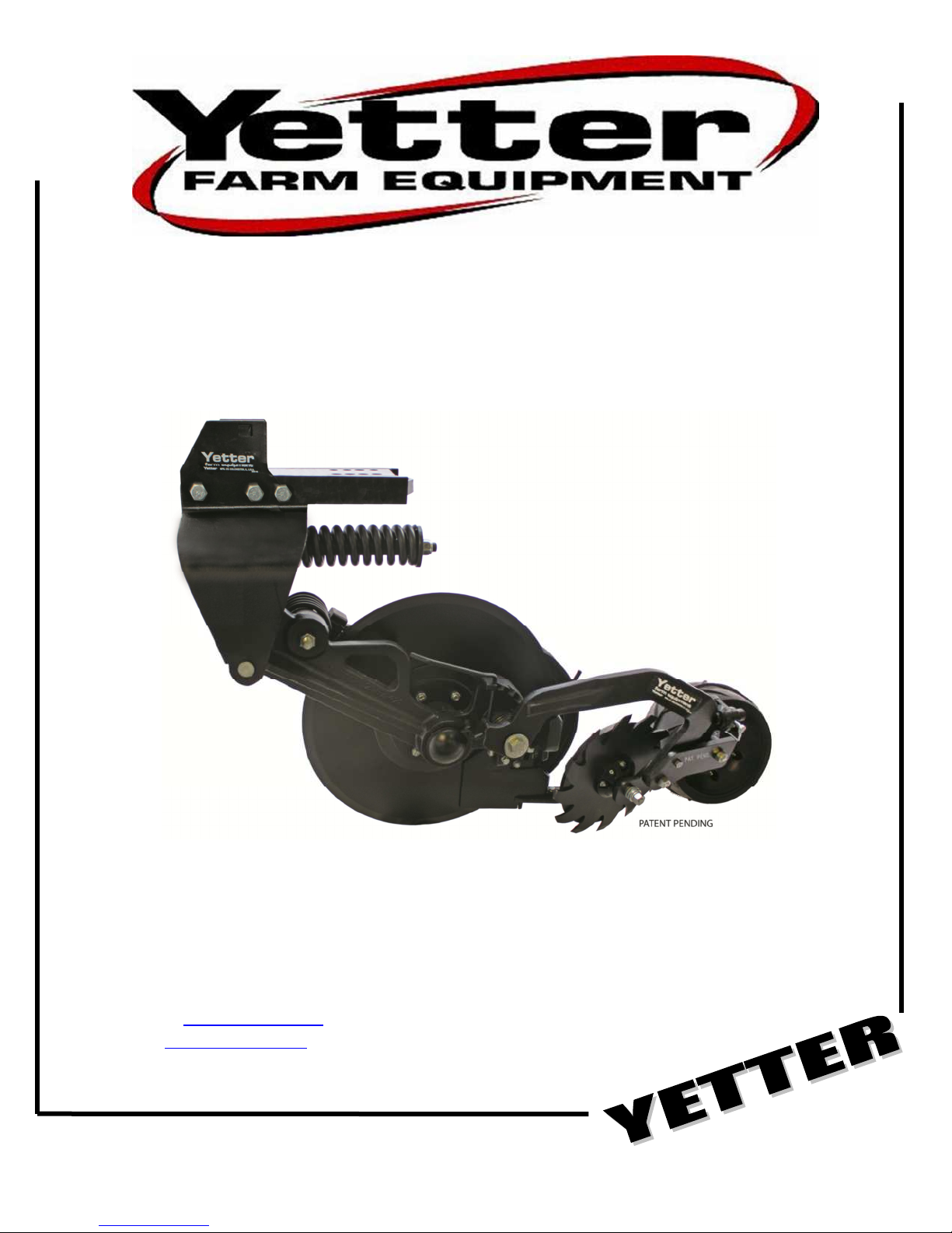
10000 SERIES MAGNUM™
FERTILIZER COULTER
YETTER MANUFACTRURING CO.
Founded 1930
Colchester, IL 62326-0358
Toll free: 800-447-5777
Fax: 309-776-3222
Website: www.yetterco.com
Email: info@yetterco.com
2565-957_Rev_D 02/2018
Page 2

FOREWORD
You’ve just joined an exclusive but rapidly growing club.
For our part, we want to welcome you to the group and
thank you for buying a Yetter product.
We hope your new Yetter products will help you achieve
both goals-increase your productivity and increase your
efficiency so that you may generate more profit.
This operator’s manual has been designed into four
major sections: Foreword, Safety Precautions,
Installation Instructions and Parts Breakdown.
This SAFETY ALERT SYMBOL indicates important
safety messages in the manual. When you see
this symbol, be alert to the possibility of
PERSONAL INJURY and carefully read the
message that follows.
The word NOTE is used to convey information that is
out of context with the manual text. It contains special
information such as specifications, techniques and
reference information of a supplementary nature.
The word IMPORTANT is used in the text when
immediate damage will occur to the machine due to
improper technique or operation. Important will apply to
the same information as specified by note only of an
immediate and urgent nature.
Yetter Manufacturing warrants all products manufactured and sold by it against defects in material. This warranty being
expressly limited to replacement at the factory of such parts or products as shall appear to be defective after inspection. This
warranty does not obligate the Company to bear cost of labor in replacement of parts. It is the policy of the Company to
make improvements without incurring obligations to add them to any unit already sold. No warranty is made or authorized to
Yetter Manufacturing warrants its own products only and cannot be responsible for damages to equipment on which
mounted.
be made, other than herein set forth. This warranty is in effect for one year after purchase.
DEALER: ________________________________________
WARRANTY
It is the responsibility of the user to read the operator’s
manual and comply with the safe and correct operating
procedure and to lubricate and maintain the product
according to the maintenance schedule in the operator’s
manual.
The user is responsible for inspecting his machine and
for having parts repaired or replaced when continued
use of the product would cause damage or excessive
wear to the other parts.
It is the user’s responsibility to deliver his machine to the
Yetter dealer who sold him the product for service or
replacement of defective parts, which are covered by the
warranty policy.
If you are unable to understand or follow the instructions
provided in this publication, consult your local Yetter
dealer or contact:
YETTER MANUFACTURING CO.
309/776-4111
800/447-5777
309/776-3222 (FAX)
Website: www.yetterco.com
E-mail: info@yetterco.com
Page 3

TABLE OF CONTENTS
Foreword ..................................................................................................... 2
Safety ........................................................................................................... 4
Torque ......................................................................................................... 5
General Information ................................................................................. 6-7
Assembly Instructions ............................................................................ 8-9
Operation .............................................................................................. 10-12
Troubleshooting ....................................................................................... 13
Maintenance ......................................................................................... 14-18
Part Identification ................................................................................ 19-44
Photo Album ........................................................................................ 45-47
3
Page 4

BE ALERT!
YOUR SAFETY IS INVOLVED.
WATCH FOR THIS SYMBOL. IT POINTS OUT IMPORTANT SAFETY PRECAUTIONS.
IT MEANS “ATTENTION---BECOME ALERT!”
It is your responsibility as an owner, operator, or supervisor to know and instruct everyone using
this machine at the time of initial assignment and at least annually thereafter, of the proper
operation, precautions, and work hazards which exist in the operation of the machine in accordance
with OSHA regulations.
Safety Is No Accident
The following safety instructions, combined with common sense, will save your
equipment from needless damage and the operator from unnecessary exposure to
personal hazard. Pay special attention to the caution notes in the text. Review this
manual at least once each year with new and/or experienced operators.
1. Read and understand the operator’s manual before operating this machine. Failure
to do so is considered a misuse of the equipment.
2. Make sure equipment is secure before operating.
3. Always keep children away from equipment when operating.
4. Make sure everyone that is not directly involved with the operation is out of the
work area before beginning the operation.
5. Make sure all safety devices, shields, and guards are in place and are functional
before beginning the operation.
6. Shut off power to adjust, service, or clean.
7. Keep hands, feet, and clothing away from moving parts. It is a good idea to remove
all jewelry before starting the operation.
8.
Visually inspect the machine periodically during operation for signs of excessive
vibration, loose fasteners, and unusual noises.
WARNING: Never work around the toolbar/implement while in a raised position without
using safety lockups.
CAUTION: The 10000 Series MagnumTM coulters are very heavy. Pay extra
attention to lifting techniques when handling or maneuvering the coulter
during assembly. Failure to do so may lead to personal injury.
4
Page 5
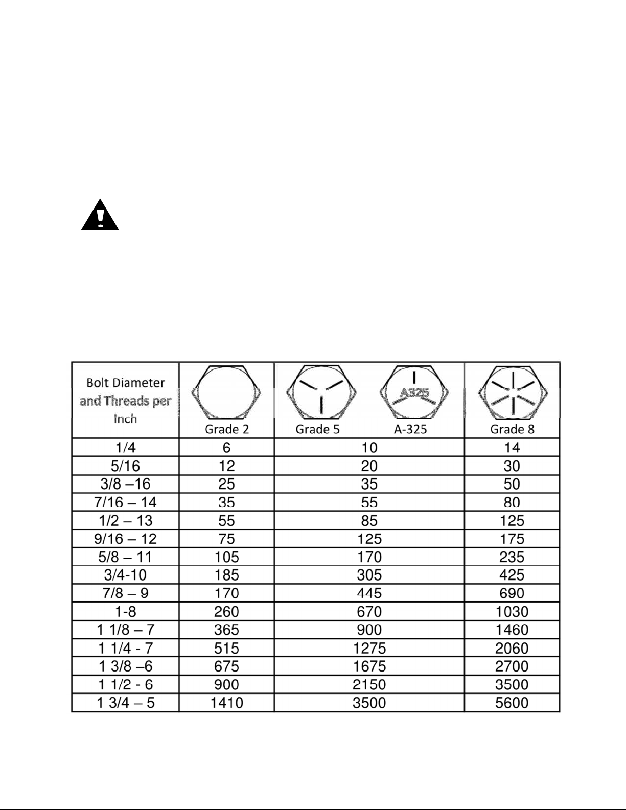
BOLT TORQUE
Before operating the 10000 Series Magnum™ for the first time, check to be sure that all
hardware is tight. Check all hardware again after approximately 50 hours of operation
and at the beginning of each planting season.
All hardware used on the 10000 Series Magnum™ is Grade 5 unless otherwise
specified. Grade 5 cap screws are marked with three radial lines on the head. If
hardware must be replaced, be sure to replace it with hardware of equal size, strength
and thread type. Refer to the torque table below when tightening hardware.
Important: Over tightening hardware can cause as much damage as when
under tightening. Tightening hardware beyond the recommended range can
reduce its shock load capacity.
The chart below is a guide for proper torque. Use it unless a specified torque is called out
elsewhere in the manual.
Torque is the force you apply to the wrench handle or the cheater bar, times the length of the
handle or bar.
Use a torque wrench whenever possible.
The following table shows torque in ft. lbs. for coarse thread hardware.
5
Page 6

GENERAL INFORMATION
Model No.
Description
Est. Wt. (lbs)
Model No.
Description
Est. Wt. (lbs)
Model No.
Description
Est. Wt. (lbs)
Model No.
Description
Est. Wt. (lbs)
10000 Series MagnumTM Fertilizer Coulter
STANDARD FEATURES FOR ALL MODELS
• High application speeds with minimal soil disturbance for fall, pre-
plant, and side-dressing applications
• Tube kits for applying liquid, dry, or anhydrous
• All cast design
• Spring loaded knife with carbide tip for extended wear
• 22.6” blade set at 4° angle.
• Fits 4x4, 4x6, 5x7, 6x4, and 7x7 toolbar sizes
• Sharktooth® Wheel Closer standard
ORDER from SECTIONS: A, B, and C
Section A:
10000-001-LH LH Magnum, w/ Walking Tandem, fits toolbars 4,5,6,7 wide univ. mount 380
10000-001-RH RH Magnum, w/ Walking Tandem, fits toolbars 4,5,6,7 wide univ. mount 380
10000-002-LH LH Magnum, w/ Walking Tandem, fits toolbars 4” wide, Short mount 375
10000-002-RH RH Magnum, w/ Walking Tandem, fits toolbars 4” wide, Short mount 375
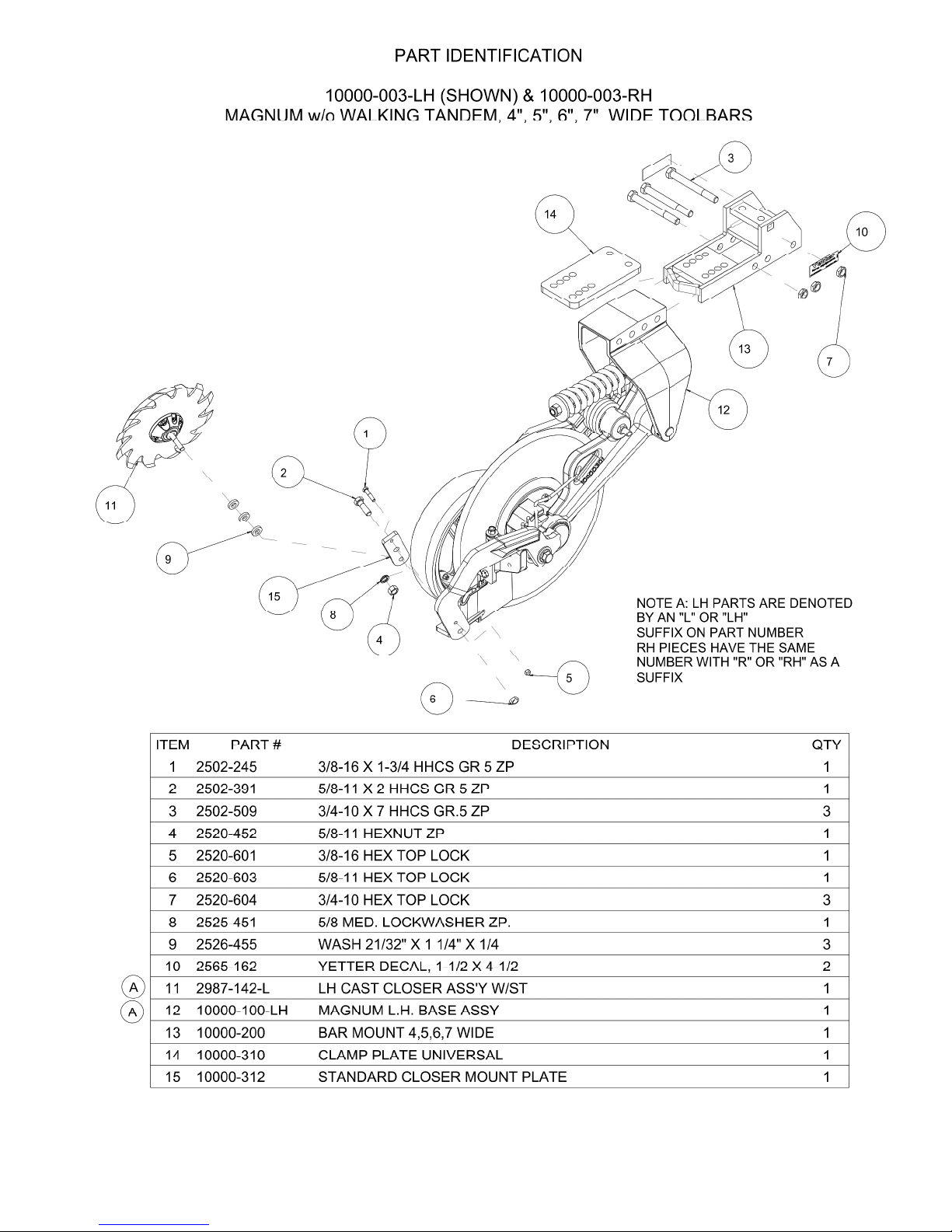
10000-003-LH LH Magnum, w/o Walking Tandem, fits toolbars 4,5,6,7 wide univ. mount 355
10000-003-RH RH Magnum, w/o Walking Tandem, fits toolbars 4,5,6,7 wide univ. mount 355
10000-004-LH LH Magnum, w/o Walking Tandem, fits toolbars 4” wide, Short mount 345
10000-004-LH RH Magnum, w/o Walking Tandem, fits toolbars 4” wide, Short mount 345
Section B:
2987-040-L LH NH3 (3/8”) Tube Kit .395
2987-040-R RH NH3 (3/8”) Tube Kit .395
2987-041-L LH NH3 w/ Liquid (3/8” Dual) Tube Kit .697
2987-041-R RH NH3 w/ Liquid (3/8” Dual) Tube Kit .697
2987-042-L LH NH3 w/ Vapor (3/8” and 3/4”) Tube Kit .954
2987-042-R RH NH3 w/ Vapor (3/8” and 3/4”) Tube Kit .954
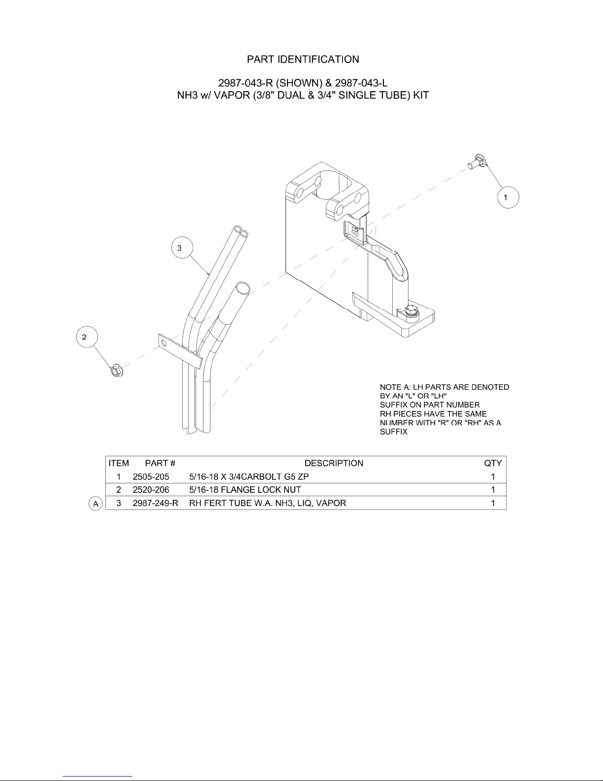
2987-043-L LH NH3 w/ Liquid and Vapor (3/8” Dual and 3/4” Single) Tube Kit 1.044
2987-043-R RH NH3 w/ Liquid and Vapor (3/8” Dual and 3/4” Single) Tube Kit 1.044
2987-044-L LH Vapor Only (3/4”) Tube Kit .455
2987-044-R RH Vapor Only (3/4”) Tube Kit .455
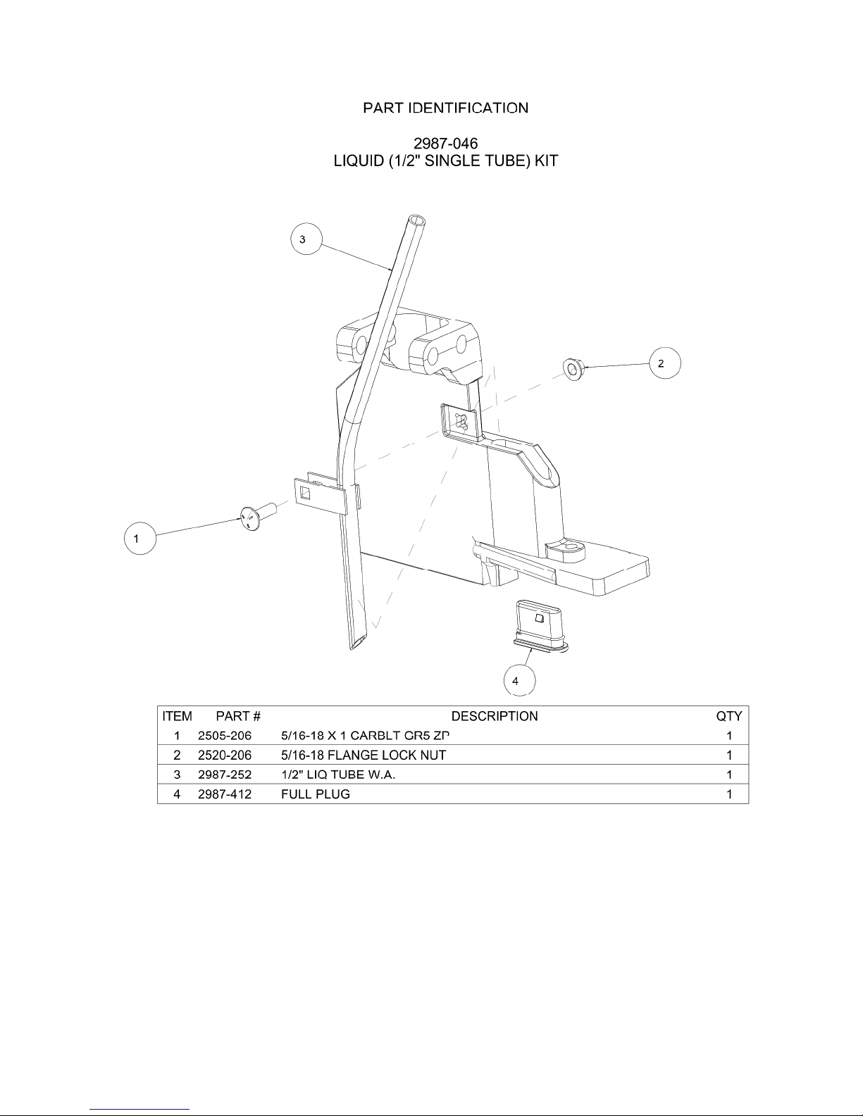
2987-046 Liquid (1/2” Single) Tube Kit .425
2987-047 Liquid (1/2” Dual) Tube Kit .850
10000-050-LH LH Magnum Dry Tube Assembly Kit 1.500
10000-050-RH RH Magnum Dry Tube Assembly Kit 1.500
Section C:
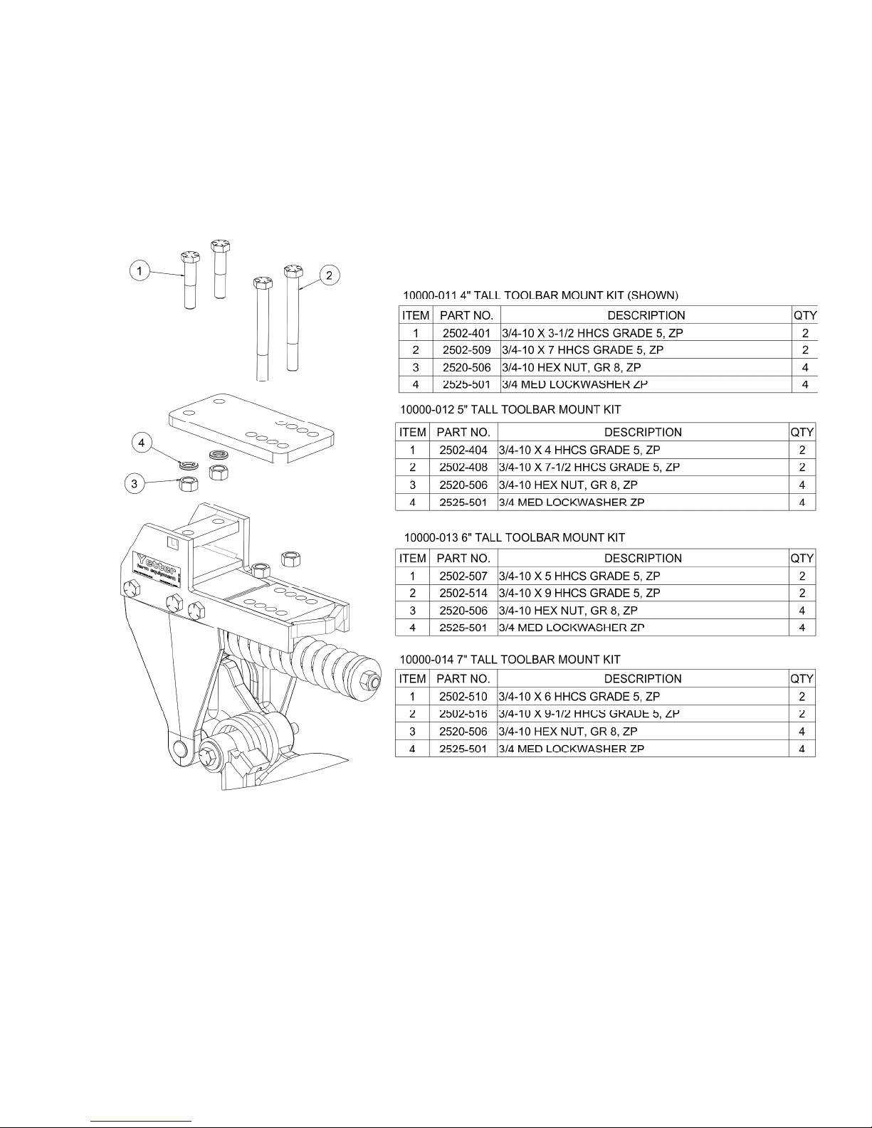
10000-011 4” Tall Toolbar Mount Hardware Kit 4
10000-012 5” Tall Toolbar Mount Hardware Kit 4.1
10000-013 6” Tall Toolbar Mount Hardware Kit 4.3
10000-014 7” Tall Toolbar Mount Hardware Kit 4.5
Optional Equipment:
10000-020-LH LH Walking Tandem Wheel Conversion Kit 28.5
10000-020-RH RH Walking Tandem Wheel Conversion Kit 28.5
10000-099 2” Drop Down Kit (For Wheel Tracks) 16.4
6
Page 7

GENERAL INFORMATION
10000 Magnum
TM
Fertilizer Coulter
7
Page 8
ASSEMBLY INSTRUCTIONS
WARNING: Never work under the toolbar while in a raised position without
using safety lockups.
WARNING: Use extreme caution, the blade is sharp and may cause bodily
injury. The coulter can be mounted to the toolbar using different techniques.
One way is to mount the main arm assembly to the toolbar and then attach
the components one at a time. Another way is to completely assemble the coulter
before attaching to the toolbar frame.
CAUTION: 10000 MagnumTM Fertilizer Coulter and its components are very
heavy. Extra attention to lifting techniques while handling and or maneuvering
the coulter during assembly is very important. Failure to do so may lead to
personal injury or death.
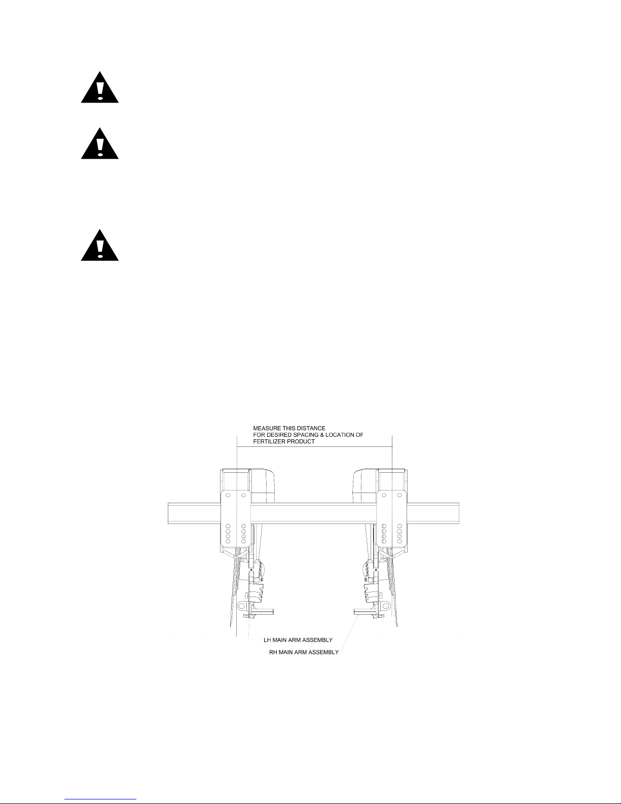
STEP 1: Mark the toolbar frame as to the location that each coulter is to be mounted.
IMPORTANT: Install an equal quantity of right hand and left hand coulters to each
section of the toolbar. Example: A 30’ – 3 section toolbar with 12 coulters (6R & 6L)
will need to install 2R and 2L coulters on each section of the toolbar. If any questions
concerning assembly of coulters, then please contact Yetter Farm Equipment for
recommendations at 800-447-5777.
Note: The coulter blade is in line with the center of the mount bracket. Measure from left
edge to left edge or from right edge to right edge to ensure the coulters are mounted at
the desired spacing.
8
Page 9
ASSEMBLY INSTRUCTIONS
STEP 2: Attach the 10000 Series MagnumTM to the toolbar using the appropriate clamp
and hardware.
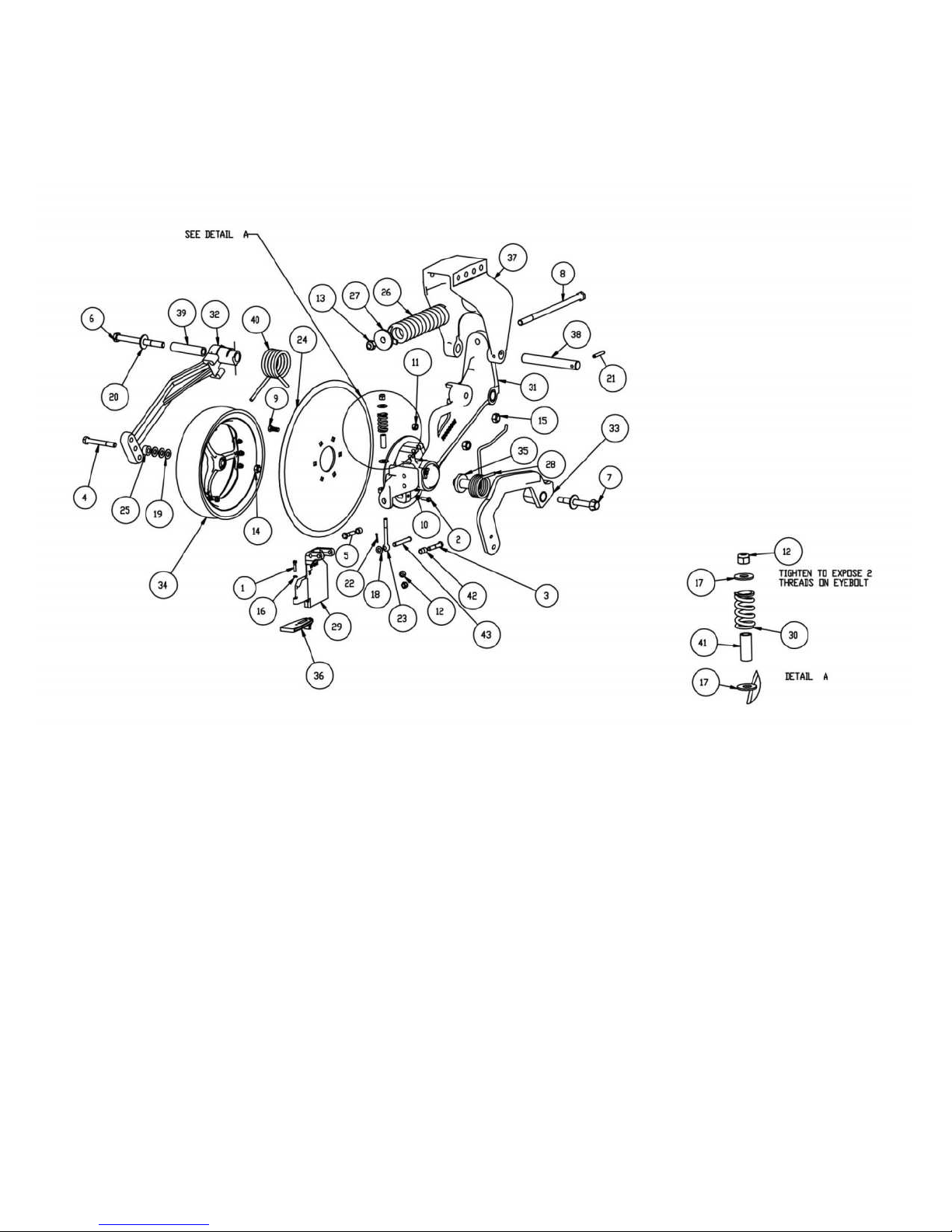
HARDWARE KITS
PART IDENTIFICATION
9
Page 10

OPERATION INSTRUCTIONS
Adjusting Opener Depth:
TOOLBAR FRAME HEIGHT ADJUSTMENT
-Raise toolbar frame for shallow
application
-Lower toolbar frame for deeper
application
Figure A: The toolbar height is set to 25” above the soil surface. To ensure that frame
heights are correct, it is important measurements are taken before use.
Figure B: The hitch is set too low while the toolbar is not parallel with the soil surface.
Note: The illustrations are intended to show that the settings are critical. Tool frame
levelness and height adjustment are very important settings for correct
performance of the 10000 MagnumTM Coulter
10
Page 11
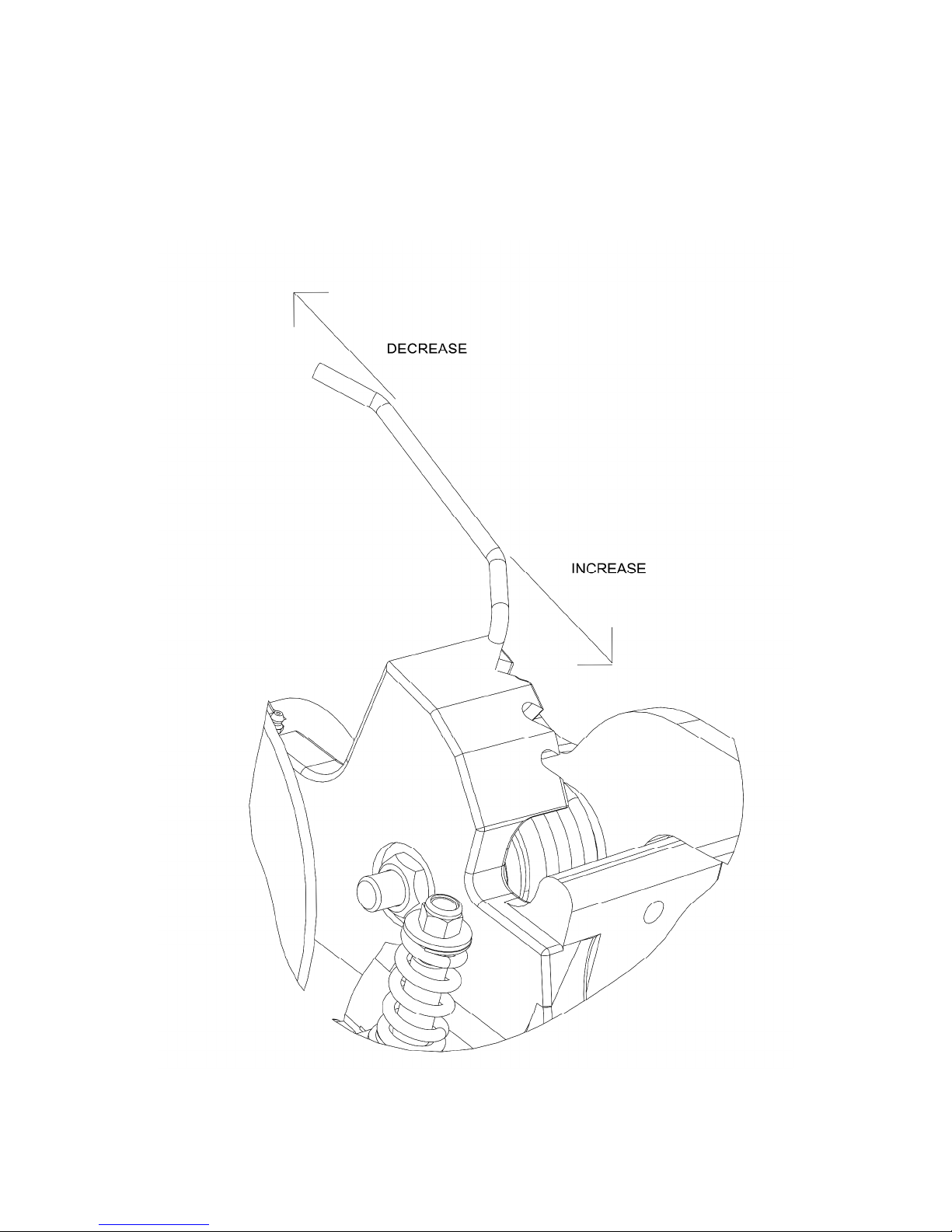
OPERATION INSTRUCTIONS
10000 MAGNUMTM CLOSING WHEEL DOWNFORCE
ADJUSTMENT
11
Page 12
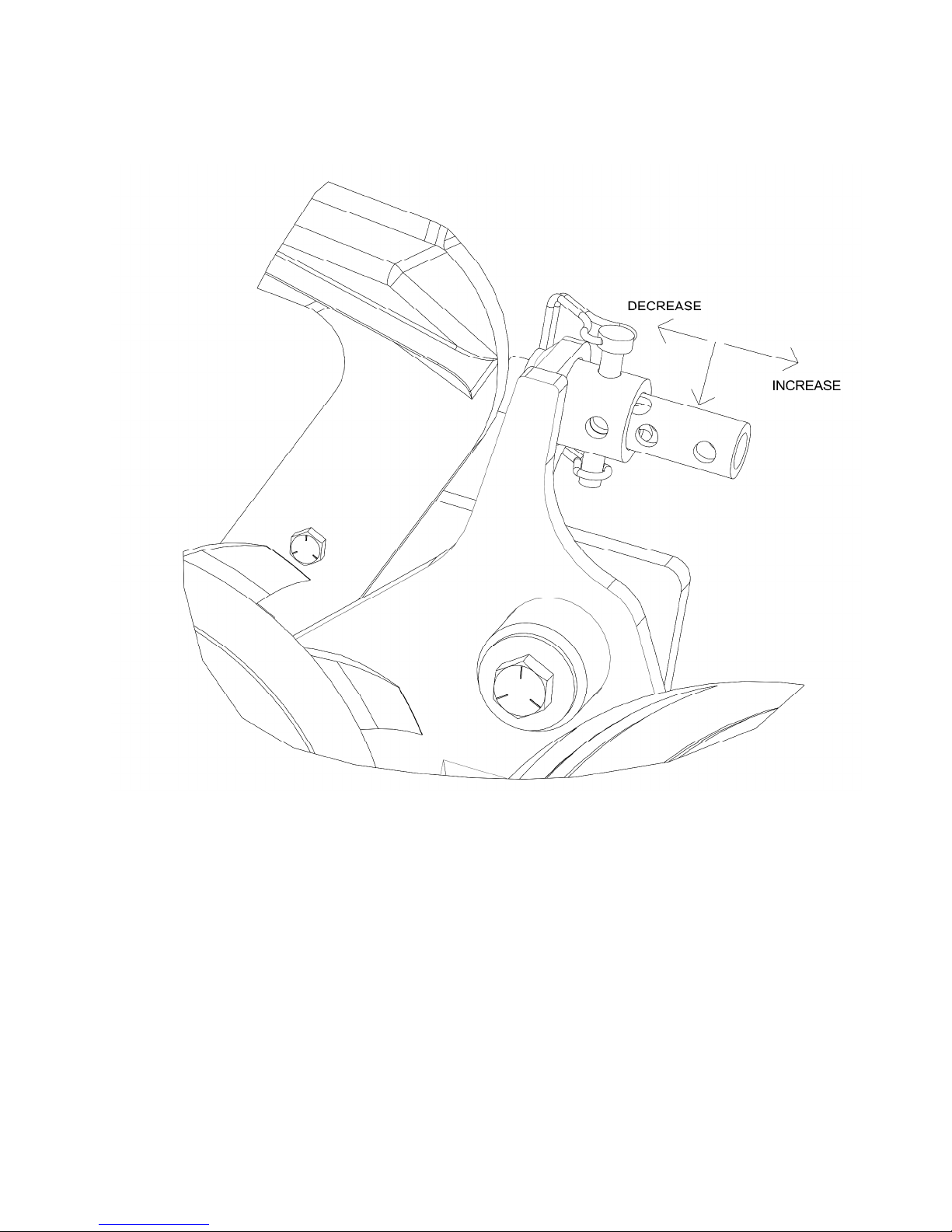
OPERATION INSTRUCTIONS
10000 MAGNUMTM WHEEL SEALER DEPTH ADJUSTMENT
12
Page 13

OPERATION INSTRUCTIONS
Symptom
Problem
Solution
Troubleshooting the 10000 Series MagnumTM Coulter
Mud builds up on press
wheels and wheels stop
turning
Poor opener penetration
Furrow not closing
Soil freezes to blade
Residue buildup in front of
openers
Uneven depth
Too much down pressure
Field is too wet
Hard ground conditions
Residue laying in bunches
Excessive residue
Dull disk openers
Disk opener worn too small
Field is too wet or overly
hard ground conditions
Raise toolbar when
Residue wedged between
scraper and disk opener
Residue laying in bunches
In adequate down pressure
Remove spring pressure
from press wheels
Wait until field dries before
running
Add weights to toolbar
frame
Spread residue evenly
across the field
Adjust toolbar for deeper
operation
Sharpen or replace opener
disks
Replace disk opener
Adjust closing wheel spring
pressure
stopping to prevent
anhydrous ammonia from
contacting and freezing soil
to blade
Verify adjustment bolt is
properly adjusted to hold
scraper against blade
Spread residue evenly
across field
Increase down pressure or
install weights
13
Page 14

MAINTENANCE
Practice Safety
Understand and practice safe service procedures before doing work. Follow ALL the
operating, maintenance, and safety information in the equipment operator’s manual.
Clear the area of bystanders, especially small children, when performing any
maintenance or adjustments. Keep work area clean and dry. Use adequate lighting for
the job. Use only tools, jacks, and hoists of sufficient capacity for the job.
Never lubricate, service, or adjust a machine while it is moving. Keep hands, feet, and
clothing free from power-driven moving parts. Disengage all power and operate controls
to relieve pressure. Lower equipment to the ground and stop the engine. Remove the
key. Wait for all moving parts to stop before servicing, adjusting, repairing, or
unplugging.
Securely support any machine elements with blocks or safety stands that must be
raised for service work.
Keep all parts in good condition and properly installed. Fix damaged equipment
immediately. Replace worn or broken parts. Remove any buildup of grease, oil, or
debris from the equipment.
Make sure all guards and in place and properly secured when maintenance work is
completed.
14
Page 15
MAINTENANCE
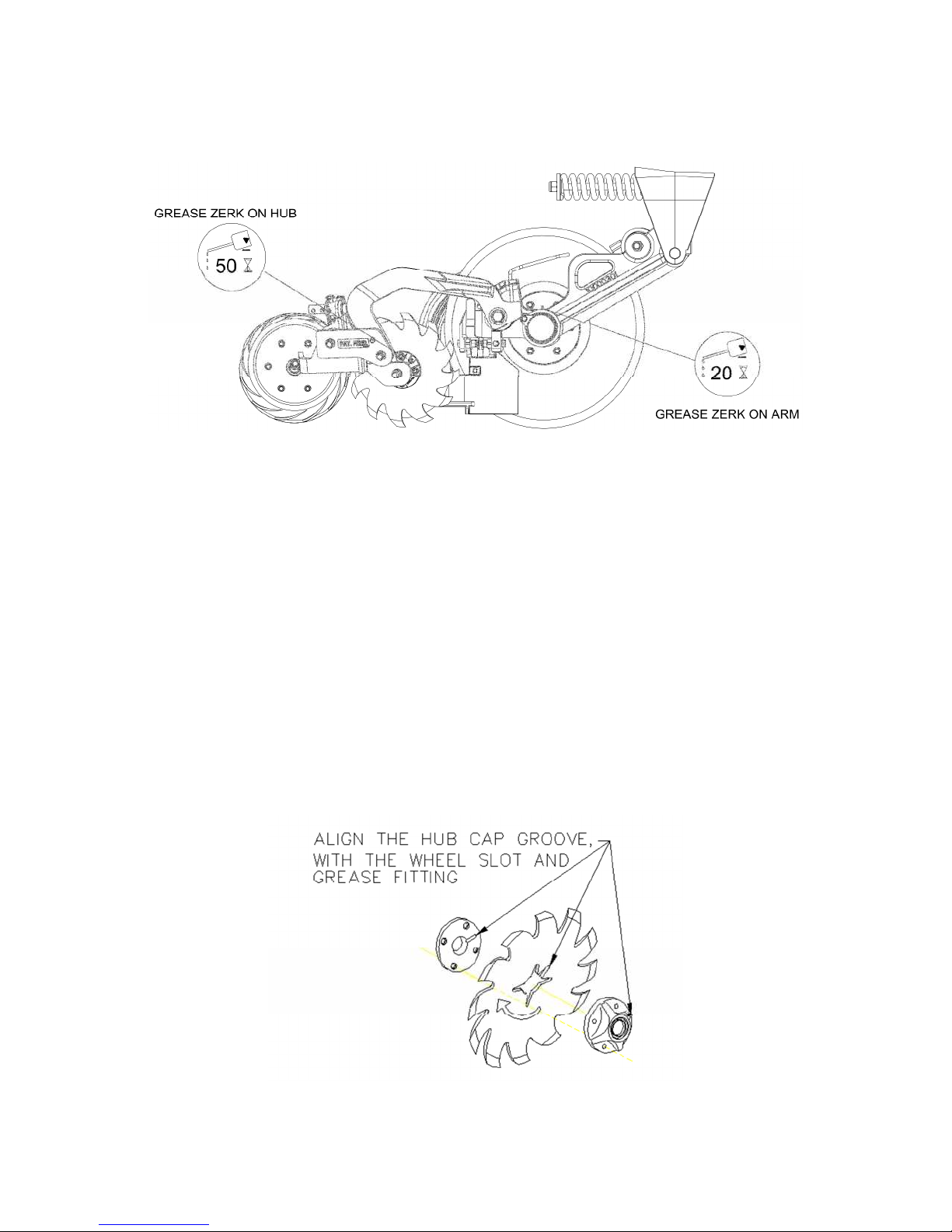
Lubrication Intervals
Lubricate with grease at hourly interval indicated on symbol.
IMPORTANT: The recommended service intervals are based on normal oberating
conditions. Severe or unusual conditions may requre more frequent lubrication.
Perform each lubrication and service procedure at the beginning and each of
each season. Clean grease fittings before using grease gun to avoid injecting dirt
and grit into the bearing. Replace and lost or broken fittings immediately. If a
fitting fails to take grease, remove and clean thoroughly, replace if necessary.
Also check for failure of adjoining parts.
Bearing Replacement Installation
1. When assembling the spoke wheels, bearing assembly, and hubcap, be sure to
align the grease transfer hole in the spoke wheel with the grove in the hubcap
and hole in the hub to allow grease passage.
2. Assembly the wheels, hubs, and caps.
3. Grease the wheel/hub/bearing assembly.
15
Page 16

MAINTENANCE
Lubrication
CAUTION: To help prevent serious injury or death to you or others, service
machinery on a level surface. Lower machine to ground or sufficiently
lock or block raised machine before servicing. If machine is connected
to tractor, engage parking brake and place transmission in “PARK”,
shut off engine and remove key. If machine is detached from tractor, block
wheels and use jack stands to prevent movement.
CAUTION: Do not clean, lubricate, or adjust machine while in motion.
Use grease based on NLGI consistency number and the expected air temperature
range during operation.
Use a multi-purpose polyurea, water resistant, moderate speed, and NLGI grade
#2 grease. Other greases may be used if they meet the NLGI performance standard.
IMPORTANT: Some types of grease thickener are not compatible with others. Consult
your grease supplier before mixing different types of grease.
Alternative Lubricants
Conditions in certain geographical areas may require special lubricants and lubrication
practices which do not appear in the operator’s manual. If there are any questions,
consult Yetter Manufacturing Co. to obtain the latest information and reccomendations.
Part # Description Ounces of Grease
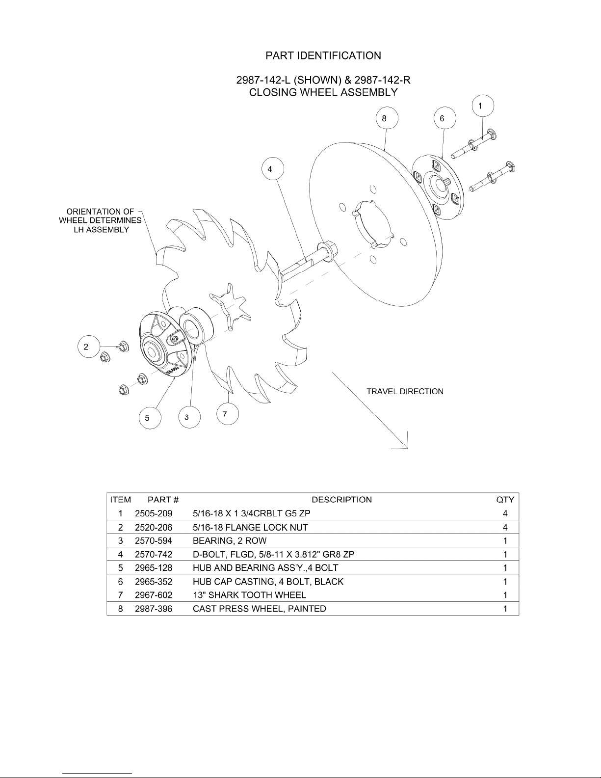
2987-142-L
Cast closer with SharkTooth Wheel 1 oz.
2987-142-R
10000-111-LH
Main Arm, Magnum Assembly 18 oz
10000-111-RH
Storing Lubricants
Your machine can operate at top efficiency only if clean lubricants are used.
Use clean containers to handle all lubricants.
Store them in an area protected from dust, moisture, and other contaminants.
16
Page 17

MAINTENANCE
Storing the Equipment
Store the machine in an area away from human activity.
Store the machine in a RAISED position.
Install service locks on all wheel cylinders.
At the end of the season the machine should be thoroughly inspected and prepared for
storage. Repair or replace any worn or damaged components to prevent down time at
the beginning of the following season. Store machine under cover with all parts in
operating condition.
• Clean machine thoroughly to remove all dirt, debris, and crop residue.
• Inspect machine for worn or broken parts. See your Yetter Farm Equipment
dealer during the off-season so parts and service can be acquired when the
machine is not needed in the field.
• Lubricate bearings as outlined in the lubrication section.
• Paint all parts which are chipped or worn to prevent rust.
• Store machine in a clean, dry location with the unit out of the sun.
• If the machine cannot be stored inside, cover with a waterproof tarpaulin and tie
securely in place
• Do not allow children to play on or around the machine
17
Page 18

MAINTENANCE
BEARING ADJUSTMENT:
1. Raise the toolbar until the blade is clear of the ground. Place a safety stand
under the toolbar. Remove the blade. Remove the hub cap, cotter pin, slotted
nut, washer and spacer from the spindle shaft assembly.
2. Pull the coulter spindle shaft assembly from the hub. Remove bearing cones and
seal.
3. Wash the old grease from the hub, bearing cups, coulter spindle shaft, seal and
bearing cones. Inspect the condition of bearing cups, cones and seal. Replace if
necessary.
4. Apply #2 multi-purpose polyurea grease on each bearing. Make sure the space
around each roller is filled. Lubricate the bearing cups.
5. Position the bearing in the cup and install the seal. Lubricate the seal lips and
proceed with re-assembly of the removed parts including the blade. Blade bolt
torque is 90 to 96 ft/lbs.
6. Tighten the slotted nut to 10 to 15 ft/lbs. or until a definite drag is felt when the
blade is turned by hand. Back off the nut one slot position to line up the cotter
pin hole with a slot. Secure the nut with a new cotter pin.
KNIFE WEAR:
The lower portion of the scraper and tube are subject to wear during operation. The
rate of wear will depend on a variety of factors and in abrasive hard soil conditions the
wear will be more rapid.
NOTE: In certain areas, replacement knives should be kept in stock, replacing worn
knives as needed.
ADJUST KNIFE TO BLADE CONTACT on each opener so the blade will turn by
hand with slight resistance, but will not coast or freewheel. In loose soil the knife
adjustment is critical. If adjustment is not maintained, soil or residue may wedge
between knife and blade, resulting in the blade not turning. Because of blade run
out, rotate the blade one full revolution after adjustment. Re-adjust knife as
needed. Never strike the knife with a heavy object or damage may occur.
To adjust, use shims or adjust knife mounting out.
18
Page 19

19
Page 20

20
Page 21
21
Page 22

22
Page 23

23
Page 24

MANUFACTURED 7/2016 – 2/2018
24
Page 25

MANUFACTURED 7/2016 – 2/2018
25
Page 26

PART IDENTIFICATION
10000-100-LH
MANUFACTURED 3/2018 - PRESENT
26
Page 27
PART IDENTIFICATION
10000-100-LH
MANUFACTURED 3/2018 - PRESENT
27
Page 28

PART IDENTIFICATION
10000-100-RH
MANUFACTURED 3/2018 - PRESENT
28
Page 29

PART IDENTIFICATION
10000-100-RH
MANUFACTURED 3/2018 - PRESENT
29
Page 30

30
Page 31

31
Page 32

32
Page 33
33
Page 34

34
Page 35

35
Page 36

36
Page 37

37
Page 38
38
Page 39

39
Page 40
40
Page 41

41
Page 42

42
Page 43

43
Page 44

44
Page 45

10000 MAGNUM
TM
RH ST SEALER
45
Page 46

10000 MAGNUM
TM
RH KNIFE
46
Page 47

10000 MAGNUM
TM
RH
TANDEM WHEEL SEALER
47
Page 48

Our name
Is getting known
Just a few years ago, Yetter products were sold primarily to the Midwest
only. Then we embarked on a program of expansion and moved into the East,
the South, the West and now north into Canada. We’re even getting orders
from as far away as Australia and Africa.
So, when you buy Yetter products . . .you’re buying a name that’s
recognized. A name that’s known and respected. A name that’s become a
part of American agriculture and has become synonymous with quality and
satisfaction in the field of conservation tillage.
Thank you.
YETTER MANUFACTURING CO.
48
Colchester, IL 62326-0358 • 309/776-4111
Toll Free 800/447-5777
Fax 309/776-3222
Website: WWW.YETTERCO.COM
E-MAIL: INFO@YETTERCO.COM
2565-957_Rev_D 02/2018
 Loading...