


2020
USER MANUAL
YDIN9020

4162, rue Burrill - Local A
WARNING
Please read this document carefully, as well as the bike-specific Installation
Guidelines, prior to assembling, installing and using the Conversion System.
Shawinigan, QC G9N 0C3
CANADA
TECHNICAL SUPPORT
If your dealer or distributor is unable to solve a problem related to the System, you may
contact the YETI SNOWMX support team from Monday to Friday.
E-mail: yetisnowmx@camso.co
Internet: www.yetisnowmx.ca
System Serial Number: 964__NSG
Original notice
Translations in other languages available at www.yetisnomx.ca
_______________
® and MC are trademarks of Camso inc.
All rights reserved. ©2019 Camso inc.
Printed in Canada.

TABLE OF CONTENTS
INTRODUCTION . . . . . . . . . . . . . . . . . . . . . . . . . . . . . . . . . . . . . . . . . . . . . . . . . . . . . . . . . . . . . . . . . . . . . . 1
SYMBOLS AND SIGNAL WORDS . . . . . . . . . . . . . . . . . . . . . . . . . . . . . . . . . . . . . . . . . . . . . 1
GENERAL INFORMATION . . . . . . . . . . . . . . . . . . . . . . . . . . . . . . . . . . . . . . . . . . . . . . . . . . . 1
SERIAL NUMBER LOCATION . . . . . . . . . . . . . . . . . . . . . . . . . . . . . . . . . . . . . . . . . . . . . . . . 1
SAFETY . . . . . . . . . . . . . . . . . . . . . . . . . . . . . . . . . . . . . . . . . . . . . . . . . . . . . . . . . . . . . . . . . . . . . . . . . . . . . 2
OPERATING INSTRUCTIONS . . . . . . . . . . . . . . . . . . . . . . . . . . . . . . . . . . . . . . . . . . . . . . . . . . . . . . . . . . . . 4
TORQUE SPECIFICATIONS . . . . . . . . . . . . . . . . . . . . . . . . . . . . . . . . . . . . . . . . . . . . . . . . . . . . . . . . . . . . . 5
ACCESSORIES . . . . . . . . . . . . . . . . . . . . . . . . . . . . . . . . . . . . . . . . . . . . . . . . . . . . . . . . . . . . . . . . . . . . . . . 5
ADJUSTMENTS . . . . . . . . . . . . . . . . . . . . . . . . . . . . . . . . . . . . . . . . . . . . . . . . . . . . . . . . . . . . . . . . . . . . . . 16
SOFT STRUT - ADJUSTMENT . . . . . . . . . . . . . . . . . . . . . . . . . . . . . . . . . . . . . . . . . . . . . . . 16
DRIVE CHAIN . . . . . . . . . . . . . . . . . . . . . . . . . . . . . . . . . . . . . . . . . . . . . . . . . . . . . . . . . . . . 18
SYNCRODRIVE BELT . . . . . . . . . . . . . . . . . . . . . . . . . . . . . . . . . . . . . . . . . . . . . . . . . . . . . 19
TRACK TENSION . . . . . . . . . . . . . . . . . . . . . . . . . . . . . . . . . . . . . . . . . . . . . . . . . . . . . . . . . 20
MAINTENANCE . . . . . . . . . . . . . . . . . . . . . . . . . . . . . . . . . . . . . . . . . . . . . . . . . . . . . . . . . . . . . . . . . . . . . . 22
LUBRICATION . . . . . . . . . . . . . . . . . . . . . . . . . . . . . . . . . . . . . . . . . . . . . . . . . . . . . . . . . . . 25
WEAR . . . . . . . . . . . . . . . . . . . . . . . . . . . . . . . . . . . . . . . . . . . . . . . . . . . . . . . . . . . . . . . . . . 28
2-YEAR LIMITED WARRANTY . . . . . . . . . . . . . . . . . . . . . . . . . . . . . . . . . . . . . . . . . . . . . . . . . . . . . . . . . . 33
TROUBLESHOOTING . . . . . . . . . . . . . . . . . . . . . . . . . . . . . . . . . . . . . . . . . . . . . . . . . . . . . . . . . . . . . . . . . 35
TOOLING LIST . . . . . . . . . . . . . . . . . . . . . . . . . . . . . . . . . . . . . . . . . . . . . . . . . . . . . . . . . . . . . . . . . . . . . . . 37
PARTS LIST . . . . . . . . . . . . . . . . . . . . . . . . . . . . . . . . . . . . . . . . . . . . . . . . . . . . . . . . . . . . . . . . . . . . . . . . . 39
YDIN9020- VERSION C
1 | YETI SNOWMX USER MANUAL
WARNING
Indicates a potentially hazardous situation which, if
not avoided, could result in death or serious injury.
INTRODUCTION
Thank you for choosing the YETI SnowMX Dirt-ToSnow bike conversion system, (hereinafter
referred to as the “System”). The YETI SnowMX is
the most advanced conversion system for off-road
motorcycle on the market. The design of its
chassis made out of light and strong carbon fiber
and its titanium components are geared towards
the needs of the most extreme riders. We went the
extra mile to offer you a quality, high-performance
conversion system that is suited to the handling
behavior of your off-road motorcycle and that will
take you to places only dreamt of while summer
riding.
SYMBOLS AND SIGNAL WORDS
This guide uses the following signal words and
symbols to emphasize particular information:
• This document is an integral part of the System.
Pass it along to any new System owner.
• Consult legal authorities where you drive your
motorcycle equipped with the System before
usage to ensure that you respect all applicable
laws and regulations.
• Motorcycle Conversion Systems are designed to
reduce ground pressure and increase vehicle
traction. However, during normal operating
conditions, vehicle speed should be reduced
compared to a wheeled vehicle.
SERIAL NUMBER LOCATION
Figures below show the location of serial numbers
on the Conversion System chassis (Figure 1) and
rubber track (Figure 2).
CAUTION: Indicates a potentially hazardous situation
which, if not avoided, may result in damage to the
motorcycle and Conversion System components.
NOTE: Indicates supplementary infor ma tio n.
The Prohibition Safety Sign indicates an
action NOT to be taken in order to avoid a
hazard.
The Mandatory Action Sign indicates an
action that NEEDS to be taken to avoid a
hazard.
GENERAL INFORMATION
• All figures, information or photos presented in
this document are up to date at the time of
publication. However, they may change without
notice.
• Read and follow carefully the indications
contained in the bike’s Owner Manual. Its
content remains applicable after installation of
the System.
• This document should be read by every person
who operates a motorcycle equipped with the
System.
Figure 1
Figure 2
YETI SNOWMX USER MANUAL | 2
SAFETY
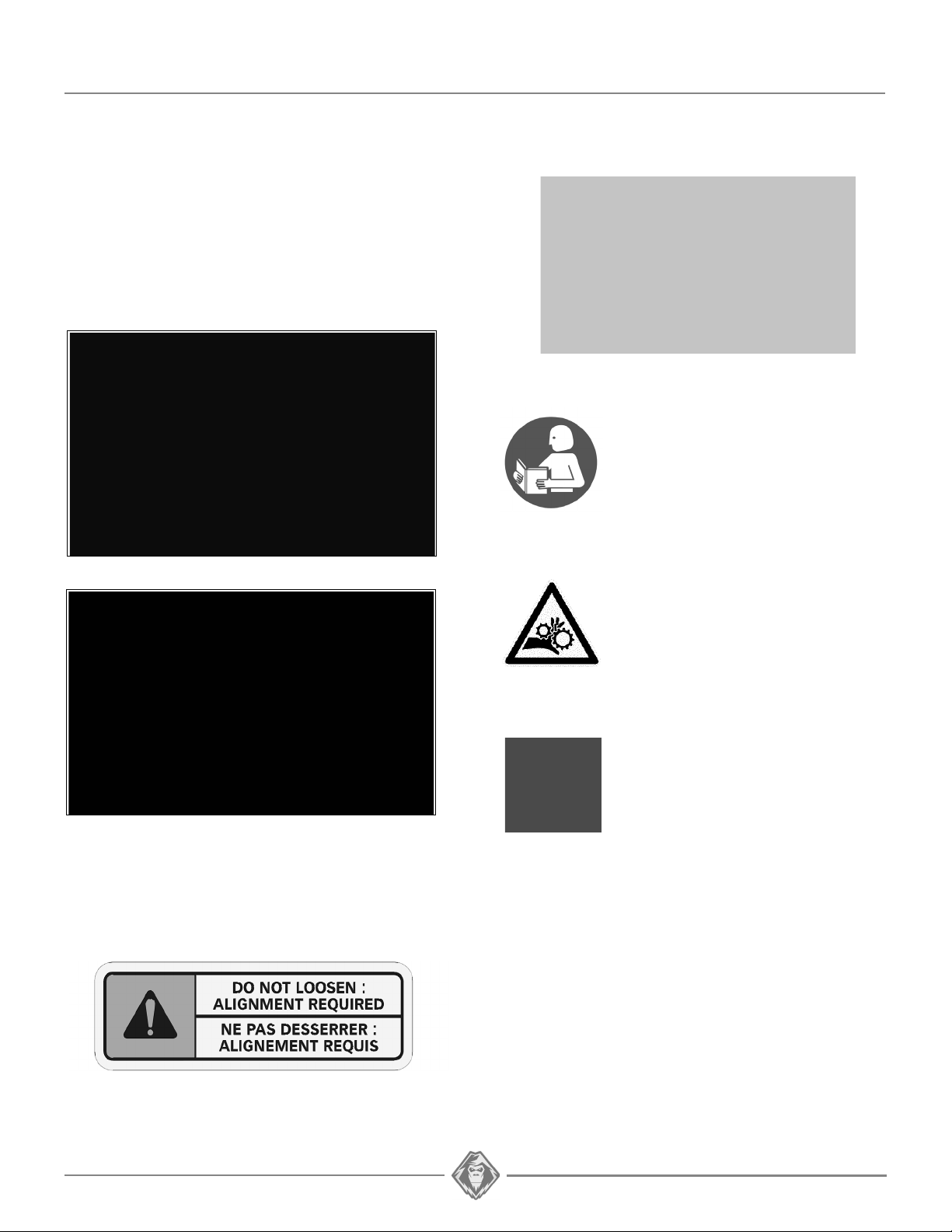
WARNING STICKERS
You will find affixed on the Conversion System the
warning stickers shown in the illustrations below.
Read the stickers carefully and understand them
before using the Conversion System. They contain
important information about safety and proper
operation of the Conversion System.
GENERAL WARNING
User Manual - Users must read the
User Manual before attempting to
operate a vehicle equipped with a
Conversion System.
If Conversion System is sold or in
any way transferred to a new user,
the User Manual must also be
transferred to the new user.
Moving Parts - Hands or fingers
caught between moving parts of the
equipment present a danger to life
or limb. Turn motor off before
servicing Conversion System.
JACK SHAFT ALIGNMENT WARNING
The Jack Shaft’s bearing housing assembly bolts
must not be loosened. The Jack Shaft needs to be
realigned if these bolts are loosened.
Maintenance Schedule - Follow
the instructions contained in the
Maintenance Schedule section of
the User Manual to ensure safe and
long–lasting operation of the
Conversion System.

3 | YETI SNOWMX USER MANUAL
USER NOTICE AND DISCLAIMER
The YETI SnowMX Dirt-To-Snow bike conversion
System is designed to provide exceptional traction
and floatation in all winter conditions.
This document holds important information
regarding driving a motorcycle equipped with the
YETI SnowMX System. It is mandatory that every
user takes the time to carefully read, understand
and then consult this reference manual and user
guide as well as the motorcycle owner's manual as
needed. When purchasing either a new or used
Conversion System, the user must obtain all
documentation related to the System, including
manuals and guides related to the motorcycle on
which the System is installed. If need be, contact
the YETI products dealer nearest to you to obtain
any additional information. You may also consult
the Yeti Web site at www.yetisnowmx.ca and
contact our technical support by email at
yetisnowmx@camso.co.
YETI believes that there are certain risks related to
the installation and use of the System. Our
experience shows that the System is safe.
However, the user must be aware of the risks
related with driving a motorcycle with the
particularities of this type of System. The
motorcycle rider must, at all times, respect all
applicable laws and regulations, the indications of
the System manufacturer and the indications from
the motorcycle manufacturer fixed by law, namely
when age restrictions exist and motorcycle base
equipment is required (headlights, flashers and
brake lights, rear view mirror, etc.). The user must
always wear adequate safety equipment, such as
a helmet, safety glasses (or visor), protective
clothing, boots and gloves. It is understood that
driving while impaired or intoxicated presents a
danger for the motorcycle user and others and is
against the law.
The System consists of many moving parts,
including transmission wheels. If an object lodges
itself or becomes jammed into the System and
blocks the track, it is mandatory to stop the engine
and the vehicle and apply the security brake
before removing said object. By avoiding to do so,
the user exposes himself to sudden movement of
the motorcycle or to breakage of a part or
component coming from the System, which could
cause severe injuries. It is also very important to
wear full length clothing and always avoid hanging
or stringy accessories.
Driving a motorcycle equipped with such a System
requires particular precautions and a knowledge of
proper driving techniques of such vehicles.
An evaluation by the user of the conditions and
terrain (state of the ground, grade of hill, density of
snow, etc.) is equally essential.
A motorcycle equipped with a System cannot
compete and/or be used to perform stunts,
acrobatics or other exploits, as these could result in
loss of control or severe injuries.
Insufficient knowledge of a motorcycle during down
hill riding, climbs and crossing of obstacles and
turns can result in tipping or roll over, and can
cause severe injuries.
Carrying a passenger, a load or attaching a tow can
cause the motorcycle to be less stable, and affect
usability. Unless otherwise prescribed by law and
by the motorcycle manufacturer, you must not carry
a passenger, loads or tow any objects.
The installation of a System:
• Increases ground clearance.
• Changes the center of gravity.
• Increases motorcycle length, width and weight.
• Reduces ground pressure.
These parameters will effectively change driving
characteristics of a motorcycle equipped with the
System.
Consequently, it is highly recommended that the
user adapt his driving style to the new
characteristics mentioned above. The rider must
always use caution when he crosses obstacles,
circulates through narrow paths, meets vehicles
coming in the opposing direction, etc.
As it was designed, the System will considerably
reduce the motorcycle top speed and can falsify
the speedometer. Generally, the System
transmission wheel diameter is less than that of the
tire. Therefore, the vehicle speed will be less than
that actually displayed. Whether the motorcycle is
equipped or not with the System, users must
always adapt the speed to actual driving
conditions. Users must never exceed speed limits
or drive faster than their capacities allow.
Excessive speed remains one of the main causes
of severe motorcycle accidents.
Camso is proud to offer dirt-to-snow motorcycle
conversion kits within its wide range of products.
Motorcycle Conversion Systems are not only
reliable, but safe. However, there are risks inherent
to riding a motorcycle equipped with the System. It
is therefore very important that the rider familiarize
himself with the proper riding techniques of a
motorcycle equipped with a System. The rider must
also adapt his riding to his experience level, and
continually evaluate operating conditions and
terrain to safely and efficiently make the best of the
YETI SnowMX motorcycle Conversion System.
YETI SNOWMX USER MANUAL | 4
VERIFICATION Install. Hour 1 Hour 8
Visual Inspection x x x
Track Tension x x x
Belt Tension x x x
Chain Tension x x x
Torque - fork clamp
bolts
xxx
Torque - Bolts on
System
xxx
Angle of Attack x x x
WARNING
Riding a bike equipped with a Conversion System
differs from riding a two-wheeled bike. We
strongly recommend following the safety
guidelines provided below to prevent any
accident and/or serious malfunction that could
impact the rider, bike or Conversion System.
WARNING
Jumping with a bike equipped with a Conversion
System is not recommended. The System was
not designed for this type of operation. A bike
equipped with a System must never be used for
races, rallies, jumps, stunts, acrobatics or any
other extreme applications.
WARNING
When travelling in groups, riders following a
motorcycle equipped with a Conversion System
should be warned of dangerous objects that can
potentially be propelled by a tracked motorcycle.
OPERATING INSTRUCTIONS
HINTS AND TIPS
• Before going out on a ride, make sure to bring
along the following: 12, 13, 15, 16-mm sockets
and wrenches; 3, 5, and 6-mm Allen keys; an ax,
a shovel, a tow cable, a container of fuel, a
screwdriver type pry bar and an adjustable
wrench.
• Generally, the slower you go, the better the
traction will be.
• On excursions on unknown or remote terrain,
make sure to have with you a cellular or satellite
phone, a first aid kit and spare parts.
• When riding off trails, always be cautious of
potential hidden obstacles.
• In deep snow, do not intentionally spin the track
(track spins while bike remains stationary). This
could cause the bike to get stuck.
BREAK-IN PERIOD
CAUTION: A break-in period is necessary to allow
system components to settle and adjust to each other.
During the break-in period (8 hours or 160 km),
follow these recommendations:
• A GOOD break-in period must be done in a
lubricated environment such as a groomed trail
or soft snow.
• A BAD break-in period can generate smoke,
odors of burned rubber or plastic as well as
plastic deposits on track clips.
CAUTION: Non-compliance with the usage
recommendations can lead to a warranty claim refusal.
CAUTION: The owner / rider is responsible for
following the recommended scheduled maintenance
described in this manual.
CAUTION: Reduce your speed at all times; a
Conversion System installed on a motorcycle does
not have the same absorption capacity as a tire.
CAUTION: Do not operate at high speed or
continuously during extended periods, in dry
conditions such as icy trails, gravel, sand, or on
asphalt. This can cause extreme heat and can melt
down suspension / track components. If you detect
any smoke or odor of burned rubber / plastic, stop
the bike and let the track cool.
• During break-in, avoid operating in dry and
clean conditions such as icy trails, gravel,
asphalt or sand.
• Progressively increase bike speed and
acceleration.
• Pay attention to any abnormal noise or odor.
PRE-USE VERIFICATION
CAUTION: Before each ride make sure that the
System’s wheels and moving parts are free and that
they are not frozen or stuck on the frame.
CAUTION: Verify that the motorcycle’s air intake is
well adapted to weather conditions and is not
blocked by snow accumulation.
5 | YETI SNOWMX USER MANUAL
DIMENSION GRADE Nm lb-ft
M6-1.0 8.8 10 7
M8-1.25 8.8 25 18
M8-1.25 10.9 33 24
M10-1.5 8.8 50 37
M10-1.5 10.9 70 52
M12-1.75 8.8 90 66
M12-1.75 10.9 125 92
WARNING
Over-tightening bolts may damage parts and
safety features may be affected.
TORQUE SPECIFICATIONS
Refer to the exploded views at the end of the
Manual to obtain torque specifications applied to
bolts at important points on the System.
NOTE: Use a thread locker (Loctite 263 type or its
equivalent) at indicated places in the exploded
views of the system.
NOTE: Release track tension during storage period
(recommended).
NOTE: Set shock absorber springs at lowest tension
position during storage period (recommended).
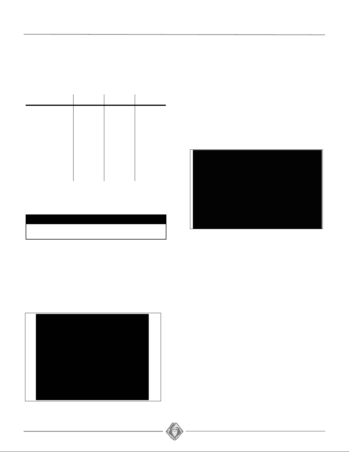
ACCESSORIES
A Wheel kit is available to help move your bike
fitted with a YETI SNOWMX Conversion kit.
NOTE: The Wheel kit, shown below in Figure 4, can be
purchased through an authorized YETI dealer.
Part #YAAC1281.
STORAGE
CAUTION: Contaminants can alter and corrode the
moving parts of the System during storage.
Performing the prescribed maintenance before
storing the System is strongly recommended.
The best way to store the System is to lay it down
on a wood pallet, away from direct sunlight.
Figure 4
SPEED REDUCTION AND IMPACT ON
SPEEDOMETER
Installation of a YETI Conversion kit on a
motorcycle affects its speed and the way the
speedometer (if present) should be read.
Depending on the bike model, the actual speed is
lowered by 35 to 40% as compared to the
motorcycle on wheels.
Figure 3

YETI SNOWMX USER MANUAL | 6
INSTALLATION INSTRUCTIONS
• These installation instructions are meant to be
used in conjunction with the bike’s User Manual.
Refer to the instructions contained in your bike’s
manual for information concerning hardware,
torque specifications, and bike assembly or
disassembly procedures.
CAUTION: The warranty does not apply if
installation of the System is done by someone other
than a YETI dealer or authorized distributor.
MOTORCYCLE PREPARATION
• Place the bike high enough on a solid and stable
stand so that the bike’s front and rear are not
touching the ground. Make sure that the bike is
immobilized and can be safely worked on.
CAUTION: Do not expose any part of your body
under the vehicle unless the motorcycle is installed
on a secure stand.
• Disassemble and remove fork protectors (if
applicable).
FRONT BRAKING SYSTEM REMOVAL
Proceed as follows:
** 129FR & 137MT models only **
NOTE: Do not disassemble the brake hose from caliper.
The motorcycle’s brake system must be
removed as one unit.
• Unbolt and disassemble the brake handle
(master-cylinder) from the handlebars.
• Remove the brake hose mounting hardware and
the entire Braking system as one unit.
** 120SS model only **
• Loosen and remove front brake caliper assembly
bolts.
• Squeeze brake lever down to the handlebar and
maintain in place with zip-tie.
Figure 5
FRONT WHEEL
FRONT WHEEL ASSEMBLY REMOVAL
Proceed as follows:
• Loosen front fork axle pinch bolts.
• Loose and remove the front wheel axle nut.
• Remove front wheel axle.
• Remove the motorcycle’s front wheel.
• Remove banjo bolt securing brake hose to
master-cylinder. Keep crush washers.
• Install rubber grommet, supplied in YETI parts
box, on banjo bolt. Reinstall and finger tighten
banjo bolt in master-cylinder.
NOTE: Rubber grommet will keep brake fluid from
leaking out of master-cylinder while Conversion
System is being assembled to bike.
• Remove assembled brake hose and caliper from
bike.
NOTE: Bleed brake fluid out of brake hose and caliper
before storing them.
NOTE: Re-use the Conversion System’s Parts box to
store the disassembled parts during the periods
the Conversion System is used.
NOTE: The nut and wheel axle will be reused to install
the ski assembly on the motorcycle.

7 | YETI SNOWMX USER MANUAL
REAR WHEEL
To prepare the bike for rear system installation,
perform the following disassembly steps:
WHEEL/REAR SUSPENSION ASSEMBLY REMOVAL
• Loosen the rear suspension swing-arm nut.
• Lower chain tension to its minimum setting.
• Disassemble brake pedal and rear mastercylinder from the motorcycle’s frame.
NOTE: Do not remove the brake hose from the caliper.
The braking system needs only to be decoupled
from the motorcycle frame.
• Remove chain guard, guide rollers, and chain
from motorcycle.
• Disassemble and remove upper shock absorber
mounting bolt.
• Unbolt from the frame the linkage between the
swingarm and the shock absorber.
NOTE: There is no lower linkage between swingarm
and shock absorber on KTM PDS models.
NOTE: On certain bike models, some components
(muffler, seat, plastic side panels or rear frame
extension) have to be temporarily removed to
allow removal of shock absorber.
• Remove rear suspension swingarm pivot shaft.
• Remove the complete swingarm/rear
suspension assembly from the motorcycle.
SPECIAL INSTRUCTION
CAUTION: Some bike models (Honda & Yamaha) are
equipped with a kickstand / footpeg unit used to
support the bike when not in use. This stand
interferes with the rear conversion system and
should be removed. The kickstand and footpeg
make up one unit; so removing the kickstand means
removing the footpeg as well and therefore the bike
becomes unusable
Two options are available:
- Remove the footpeg / kickstand unit and replace
it by a footpeg without kickstand available from
the OEM (best option).
- Cut away the kickstand portion of the unit and
render it unusable.
DISASSEMBLED PARTS
Some of the components removed from the bike
will be re-used for the Conversion System
installation:
• Front wheel axle and nut.
• Rear swingarm axle and nut.
• Upper shock absorber bolt and nut.
• Crankcase Chain cover and bolts.
NOTE: All other components can be stored. Re-use the
Conversion System parts box to store the
disassembled parts when the Conversion
system is in use.
NOTE: The swingarm/rear suspension assembly should
separate completely from the motorcycle.
• Remove mud deflector from rear part of frame.
Bikes equipped with a kick stand.
• Disassemble and remove the kickstand.
YETI SNOWMX USER MANUAL | 8
SPINDLE INSTALLATION
FORK CLAMP VERIFICATION
Verify that the fork clamps received in the
installation kit are the right size and fit perfectly on
the bike’s forks.
CAUTION: A clamp that is too loose on the fork tube
does not allow for rigid assembly with the ski and
may damage the fork tube.
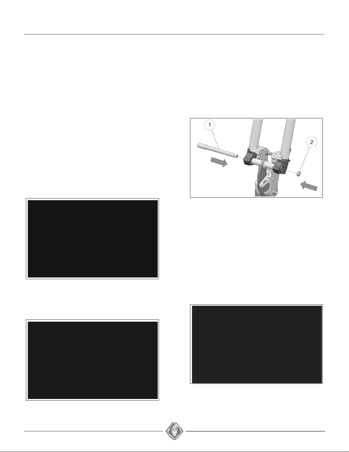
INSERTION OF SPINDLE BETWEEN FORK
TUBES
Proceed as follows:
NOTE: Center carbon blade must be positioned toward
the bike’s front.
• Install the complete spindle (1) between the two
lower fork tubes (2). Twist and slide spindle
down to position it between the fork tubes. See
Figure 6.
NOTE: Depending on bike model, the left and right axle
spacers on each side of the carbon blade may
be the same or different. If you are uncertain
about their position, consult the YETIVERTER
tool on YETISNOWMX.CA
NOTE: Make sure axle spacer locater collar is through
the center carbon blade.
• Insert front wheel axle (1) through forks and axle
spacers to secure spindle assembly. Install axle
nut (2) and tighten temporarily by hand. Figure 8.
NOTE: Lube wheel axle before assembly.
Figure 8
Figure 6
• Position left (1) and right (2) axle spacers on
each side of the spindle’s center carbon blade.
See Figure 7.
• Set the outer fork clamps (1) in their position at
the bottom of the forks. The small machined
diameter in the fork clamps is used as clearance
for fork seals and so must be positioned up.
Insert clamp assembly bolts (2); do not tighten at
this point. See Figure 9.
CAUTION: Observe installation direction for outer
fork clamps. A clamp assembled in the wrong
direction could damage the fork if the front
suspension travels all the way down.
NOTE: Apply a thread locker produ ct (e. g. Blue Loctite
242) to Fork clamp assembly bolts.
Figure 7
Figure 9
NOTE: Depending on bike model, the left and right fork
clamps may be the same or different. If you are
uncertain about their position, consult the
YETIVERTER tool on YETISNOWMX.CA

9 | YETI SNOWMX USER MANUAL
LUBE
CAUTION: Clamps must be straight and aligned
before final tightening. Clamp misalignment can
hinder normal operation of forks.
• Tighten, in sequence, the front wheel axle nut (1)
and then the pinch bolts (2) at the bottom of the
forks to the torque specifications recommended
by the manufacturer of the bike. Figure 10.
• Tighten clamp bolts (3) to 25 Nm [18 lb-ft] of
torque. See Figure 10.
NOTE: Use an alternate tightening sequence between
the 4 clamp bolts (3) to distribute force equally.
Figure 10
SKI INSTALLATION
Assemble ski to spindle as follows:
• Check if «FRONT» marking under ski rubber is
positioned towards front of ski. Figure 11.
Figure 12
REAR SYSTEM PREPARATION
VERIFICATION OF ADAPTERS AND BUSHINGS
Check that the mount adapters and bushings
received match your bike’s model. These parts are
identified by a number inscribed on each one;
consult the YETIVERTER tool on
YETISNOWMX.CA to confirm the parts and identify
their installation position.
MOUNT ADAPTER INSTALLATION
Assemble mount adapters to Bike Mount as
follows:
NOTE: Make sure to assemble the correct adapters on
the Bike Mount’s left (1) and right (2) sides.
• Apply lube on the portion of adapters inserted in
Bike Mount. Figure 13.
Figure 11
• Position ski (1) to spindle (2) and align holes in
ski’s base with mounting hole in spindle. Insert
M10x110mm bolt (3) and secure with M10
locking nut (4). Tighten assembly to 55 Nm
[38lb-ft] of torque. See Figure 12.
Figure 13

• Place mount adapters (1) in position outside of
Bike Mount (2). Finger tighten the temporary
M8x25mm assembly bolts (3) provided, at the
small end of the adapters. See Figure 14.
Figure 14
• Using the provided Mount adapter insertion tool
(1) and the M8x25mm bolts (2), rotate and
alternate between the tool’s nut (3) and bolt (2)
to insert mount adapters on both sides of the
Bike Mount. See Figure 15.
NOTE: Rotate slowly and alternate a few times to avoid
jamming the adapter during insertion.
YETI SNOWMX USER MANUAL | 10
Figure 16
CAUTION: To ensure adequate assembly, the
M8x25mm bolts used to insert the adapters must be
relocated to the Bike Mount’s front inside M8 holes.
• Insert bushings in mount adapters. Make sure to
match the bushings to the correct adapters.
NOTE: Depending on your bike model, the left and right
adapter bushings are the same or differ. If you
are uncertain about their position, consult the
YETIVERTER tool on YETISNOWMX.CA
AUTOMATIC CHAIN TENSIONER
INSTALLATION
Figure 15
• Remove M8x25mm bolt used to insert Bike
Mount adapter.
NOTE: Apply a thread locker product (e . g. Blue Loct ite
242) to Mount adapter assembly bolts.
• Secure adapters to Bike Mount with the longer
M8x25mm bolts (1) installed inside (3) and the
shorter M8x20mm bolts (2) on the outside (4).
Tighten bolts to 25 Nm [18 lb-ft]. See Figure 16.
• Insert Chain tensioner (1) on mount adapter (2)
installed on left side of Bike mount. Apply
pressure to insert guard on larger part of adapter.
Next, insert the chain tensioner spring (3) in its
seats, in the Chain tensioner and mount adapter.
See Figure 17.
Figure 17

11 | YETI SNOWMX USER MANUAL
BIKE MOUNT ADJUSTMENT
Before mounting the rear system to the bike, the
Bike mount must be extended out at its farthest
point. Proceed as follows:
• Loosen nut on eccentric bolt (1) and the Bike
mount M8 adjustment bolts (2).
• Using a 12mm socket, rotate eccentric bolt to
move the Bike mount out. See Figure 18.
Figure 18
• Insert spacer bushings (6) and o-rings (5) in both
sides of Soft Strut upper eye.
• Set aside the 2 spacer bushings (7); they will be
installed later.
NOTE: For KTM models with PDS suspension, the Soft
Strut assembly differs from the one illustrated in
Figure 19.
SOFT STRUT INSTALLATION
• Position the Soft Strut upper eye to the bike’s
shock absorber upper mount.
IMPORTANT: Spacer bushings (6) and o-rings (5)
must be installed and positioned correctly in upper
eye of Soft Strut.
• Assemble Soft Strut (1) using the bike’s shock
absorber assembly bolt (2). See Figure 20
SOFT STRUT PREPARATION
Before installing Soft Strut on your bike, the strut
components must be assembled as shown in
Figure 19. Proceed as follows:
Figure 19
• Assemble rod end connector (1) to strut body(2).
Tighten connector adequately to body.
• Thread lock nut (3) on rod end (4).
• Assemble the rod end w/nut to strut connector.
Figure 20
• Tighten shock assembly bolt (2) to
manufacturer’s recommended torque
specification. Figure 20.
NOTE: Apply threadlocker product on bolt as per the
manufacturer’s specification.
• Slip one o-ring (5) on each spacer bushing (6).

REAR SYSTEM INSTALLATION
NOTE: The YETI’s bike mount adapters have the same
dimensions as your swing arm bushings. You
might have to wiggle or slightly pry to open the
gap to install the YETI in the bike’s frame.
• Assemble the rear system to the bike as follows:
• Slide the YETI Conversion System (1) into
position to align Bike mount adapters (2) where
your bike’s swing arm (3) used to be. See Figure
21.
YETI SNOWMX USER MANUAL | 12
Figure 23
• Loosen and remove bike mount bolt (1) to install
the Soft Strut’s rod end in the Strut block (2). See
Figure 24.
Figure 21
• Attach YETI to bike by reinstalling swing arm
assembly bolt (1) and nut (2). See Figure 22.
Figure 22
• Tighten bolt to the bike manufacturer’s
recommended specification.
• Insert the 2 remaining spacer bushings (7) in the
Soft Strut’s rod end. See Figure 23.
Figure 24
• Raise rear of YETI System and align the Soft
Strut rod end and Strut block in Bike mount.
IMPORTANT: Make sure Spacer bushings are
correctly positioned in Soft Strut rod end.
• Re-insert assembly bolt (1) to attach Soft Strut
(2) to Bike mount. Do not tighten the bolt
completely at this point. See Figure 25.
Figure 25

13 | YETI SNOWMX USER MANUAL
WARNING
The braking system is an important safety feature
of your YETI conversion system and must be
kept in good running order. It is the operator’s
responsibility to keep the Conversion System in
optimal running order. Failure to perform
maintenance or verifications before use of
Braking system could result in a loss of control
that could cause serious injury or death.
CHAIN INSTALLATION
Before installing the chain, the Bike mount should
be retracted as much as possible.
NOTE: For the next step, the bike should be raised
slightly so that the track is off the ground and
can be rotated.
• Insert chain (1) in upper opening at the front of
the system and feed it over jack shaft drive
sprocket (2). See
Figure 26
• Slowly rotate the YETI’s track to advance chain
links on the sprocket. Use a hook or magnet to
extract the chain out of the chassis through the
lower opening at the front. See Figure 27.
Figure 26.
CAUTION: The chain has the right length and does
not need to be shortened.
CAUTION: Observe direction of insertion for master
link locking clip.
CAUTION: Do not remove grease applied on master
link pins.
Figure 28
IMPORTANT: Chain adjustment is not done at
installation but will be done later. Leave play in the
chain to allow for other necessary adjustments to
be done first. Soft Strut adjustments impact chain
tension and therefore must be done before
adjusting chain tension.
NOTE: For further details on adjustments to be
performed on the Conversion System, see the
section entitled “Adjustments”.
Figure 27
• Install the provided chain on the engine sprocket
and join the ends using the master link. See
Figure 28.
BRAKE SYSTEM
IMPORTANT: YETI SnowMX recommends that
assembly, preparation and brake system setting
steps be performed by a YETI SnowMX dealer.
YETI SNOWMX USER MANUAL | 14
WARNING
Do not mix brake fluid types or grades. Some are
not compatible. Using the wrong type or mixing
incompatible fluids may cause loss or
inadequate breaking which may result in serious
injury or even death.
BRAKE LINE ROUTING
Two options are available to route the brake line:
- Route brake line along the chassis up to the
handlebars without removing any bodywork
component.
- Disassemble bodywork components to enable
easy routing of line and master-cylinder up to
handlebars.
No matter the chosen method, observe the
following recommendations:
• Follow existing line and cable routing.
• Re-use existing ties and clips to secure brake
line. Add more ties if needed.
• Do not position the brake line against sharp
edges in the Bike’s chassis.
• Maintain large radiuses in brake line to avoid
pinches.
• Keep line away from heat sources that can
damage it or overheat hydraulic fluid.
** 120SS model only **
BRAKE LINE HOOKUP & BLEEDING
IMPORTANT: To perform the following steps, use a
new bottle of brake fluid that meets the bike
manufacturer’s specifications.
• Insert the clear plastic tube at the end of the
medical syringe. These two items are included in
the common parts box shipped with your YETI.
• Open the brake caliper’s bleeder check valve
about ½ turn and push the other end of the
plastic tube on the bleeder valve.
• Position the new fluid bottle securely at
handlebar level. Submerge end of brake line in
brake fluid.
• Keep enough play in Brake line between
handlebars and chassis, to ensure that turning
radius is not reduced.
CAUTION: Presence of an important heat source
near the line, such as an exhaust pipe, or the
engine, can overheat the Braking system’s
hydraulic fluid and render it less effective. Route
the Brake line to bypass such heat sources.
** 129FR & 137MT models only **
• Install the master-cylinder on the handlebars at
the same position occupied by the original
braking system.
• Re-assemble all motorcycle components
removed during the Conversion’s System
installation and routing of the brake line (rear
frame section, exhaust, plastic side panels, tank,
seat, etc.). Observe the manufacturer’s torque
specifications when tightening bolts.
CAUTION: Be sure to apply the bike manufacturer
requirements at reassembly of components.
NOTE: There must not be any loop in the brake line.
Keep it in an uphill position during the next step.
IMPORTANT: In the next step, the brake line end
must be submerged continuously in fluid.
• Pull on the syringe to fill the line and brake
caliper.
• Once brake fluid has started filling the syringe,
give it a pull to fill it completely. Then close the
bleeder check valve on the brake caliper.
• Remove end of plastic tube from bleeder valve.
NOTE: Squeeze the new brake fluid contained in the
syringe back into the brake fluid bottle.
• Remove end of brake line from brake fluid bottle.
and keep it in an upward position.
15 | YETI SNOWMX USER MANUAL
WARNING
Apply the recommended torque to banjo bolt in
master cylinder. Inadequate tightening of banjo
bolt may cause loss or faulty breaking which may
result in serious injury or even death.
** 120SS model only **
IMPORTANT: During the next steps, keep the end
of the brake line in an upward position to avoid
formation of air pockets in your primed brake line.
• Remove banjo bolt and rubber grommet inserted
temporarily during front brake disassembly.
• Insert banjo bolt (1) in end of brake line (2)
making sure to install the copper crush washers
(3) against both sides of the brake line banjo
end. See Figure 29.
Figure 29
• Reconnect plastic tube to brake caliper bleeder
valve. Open bleeder valve about ½ turn.
IMPORTANT: In the next step, check fluid level in
master cylinder reservoir and keep it full at all
times.
• Pump the brake lever fully. Check for air bubbles
in the fluid leaving the braking system and going
in the syringe. When there are no more air
bubbles, close caliper bleeder valve.
• Tighten bleeder valve to 5 Nm (44 lb-in). Reinstall
rubber dust cap on bleeder valve.
• Fill master cylinder reservoir to the rim. Reinstall
reservoir cover and tighten cover screws
according to manufacturer’s recommendations.
IMPORTANT: It is important to OVER FILL the
reservoir before putting the cover back on to
prevent air from entering the braking system if you
happen to tip the bike upside down while riding.
BRAKING SYSTEM VALIDATION
Perform the following test after assembly and
bleeding of the braking system.
• Engage by hand banjo bolt - brake line - crush
washers assembly in the bike’s master cylinder.
Then tighten banjo bolt to the manufacturer’s
torque specifications.
• Cut the zip tie that was installed temporarily on
the brake lever during the front brake
disassembly.
• Remove the master cylinder cover.
BRAKE LINE BLEEDING (ALL MODELS)
• Top off master cylinder reservoir with the same
new fluid used to prime your brake line.
• SLOWLY wiggle front brake lever in small
increments of ¼ - ½ lever travel at first. Pull lever
until there are no more air bubbles in brake fluid.
• Pump the brake lever a few times and tie it in the
closed position during 24 hours.
NOTE: Use a zip tie if the master cylinder does not have
a brake lever lock.
- If the system maintains pressure after 24 hours,
it is bled correctly.
- If the lever is even more closed after 24 hours,
check for fluid leaks in the braking system. if a
leak is detected, disassemble the braking system
and repair the leak.
- If there are no leaks and the lever is abnormally
closed, re-bleed the braking system.

YETI SNOWMX USER MANUAL | 16
ADJUSTMENTS
CAUTION: Adjustment settings on your YETI must
be verified after first use on the bike. Soft Strut
setting, rubber track tension, Syncro belt tension
and chain tension must be re-checked. Incorrect
adjustments can decrease system performance and
produce premature wear on certain components.
SOFT STRUT - ADJUSTMENT
Adjustment of the Soft Strut has a direct impact on
the bike’s handling. Modifying the Strut adjustment
according to the changing snow conditions has a
radical effect on ski behavior.
• Place bike on ground, supported on ski skag and
rubber track.
Front Measurement Point (A): Measure distance
between top of rail slide and the ground, at 1.00”
(25mm) back of front shock lower mounting bolt.
Figure 30.
Back Measurement Point (B): Measure distance
between top of rail slide and the ground, at 1.00”
(25mm) back of back shock lower mounting bolt.
Figure 30.
• At the front measurement point (A), measure
distance (X) between the top of the rail slide and
the ground. See Figure 31.
Figure 31
• At the rear measurement point (B), measure
distance (Y) between the top of the rail slide and
the ground. See Figure 32.
Figure 30
Recommended setting: The rear measurement
must be 0.300 to 0.500” (7,6 to 12,7 mm) higher
than the front measurement with the suspension
on the ground.
Figure 32
• Calculate the difference between the rear and
front measurement points.
Rear (Y) - Front (X) = 0.3 to 0.5” (7,6 to 12,7 mm)
Reaction to Soft Strut adjustment:
- One complete counterclockwise
rotation of the
Soft Strut shortens it by 0.050” (1,27 mm). The
rear measurement (Y) will then increase 0.050”
per rotation.
- One complete clockwise
rotation of the Soft
Strut lengthens it by 0.050” (1,27 mm). The front
measurement (X) will then increase 0.050” per
rotation.

17 | YETI SNOWMX USER MANUAL
• Loosen the rod end lock nut (1). Adjust length of
rod end by rotating the Soft Strut (2) using a 31mm wrench. See
Figure 33
NOTE: Each time Soft Strut adjustment is checked,
raise bike’s rear and lower it back down slowly.
Figure 33.
• Adjust length of Soft Strut until the rear
measurement point is 0.300 to 0.500'' higher
than the front measurement point.
• Once the Soft Strut adjustment is completed,
tighten the lock nut (1) back to 40 Nm [30 lb-ft].
An adjustment above 0.500” at the rear
measurement point:
- lowers ski pressure;
- shortens the bike’s virtual wheelbase;
- produces more skittish handling on trails;
- produces better handling at low speeds.
CAUTION: An adjustment above 0.750” at the rear
measurement point is not recommended. The bike
then becomes hard to handle and unpredictable.
SHOCK ABSORBER ADJUSTMENT
Two (2) shock absorber combination options are
available for YETI SnowMX 2020 models:
Option 1: ELKA Stage 3, front & rear
Option 2: ELKA Stage 5, front & rear
ELKA Stage 3
(front & rear option 1)
Spring preload and compression can be adjusted
on these shock absorber model.
Basic Tuning
An adjustment of under 0.300” or 0.000” (Flat)
at the rear measurement point produces:
- a better angle of attack for hill climbing;
- better handling in deep or powder snow;
- greater ski pressure;
- more stability at higher speeds.
An adjustment of between 0.300” and 0.500”
higher at the rear measurement point is:
- the recommended adjustment for all conditions;
- the best compromise suited for various uses
and snow conditions.
ELKA Stage 5
(front & rear option 2)
Spring preload, compression and rebound can be
adjusted on these shock absorber models.
Spring Preload
The shock absorbers are factory set for a 180-lbs
rider. Spring preload on shock absorbers can be
adjusted to take into account a rider’s weight and
riding style.
Proceed as follows:
• Loosen the spring preload adjustment ring
locking screw a few turns. Use a 3-mm Allen key.
• Rotate adjustment ring to raise or lower shock
absorber spring preload. Use the provided tool.
NOTE: Rotating ring clockwise lowers spring preload.
NOTE: Rotating ring counterclockwise raises spring
preload.

YETI SNOWMX USER MANUAL | 18
• Once adjustment is completed, tighten
adjustment ring locking screw.
IMPORTANT: Modification of Shock absorber
spring preload impacts Soft Strut adjustment. Soft
Strut adjustment must absolutely re-checked if the
shock absorber spring preload is modified.
CAUTION: Spring preload must be set at a level
sufficient to keep the spring seated solidly in place.
Damage to components could occur if spring
preload is too low.
CAUTION: Minimum front a-arm shock absorber
spring preload should result in a distance of not
less than 23mm between preload ring and start of
threaded portion of shock body. See Figure 34.
DRIVE CHAIN
IMPORTANT: Soft Strut adjustment must be
completed before adjusting the drive chain tension.
• Position the bike level on the ground
• Lift automatic chain tensioner (1) off the chain
and keep it up (e. g. with a zip tie) to avoid
adding tension to the chain during adjustment.
See Figure 35.
Figure 35
Figure 34
Compression and Rebound
Following the option chosen at purchase of your
YETI SnowMX, shock absorbers can be adjusted
in compression and rebound.
ELKA
shock absorbers
Consult the ELKA owner’s manual provided with
your YETI for more details relative to compression
and rebound settings (if applicable).
• Loosen eccentric bolt nut (1) a little using the
special socket provided in your YETI SnowMX
parts kit. Figure 36.
• Loosen slightly, the two M8 bolts (2), and the
four M10 bolts (3-4) on each side of the Bike
Mount so that the Bike Mount assembly can
slide. Figure 36.
Figure 36
NOTE: Be careful to not loosen the two bolts (2) too
much; T-nuts could fall out and be lost.
• Rotate eccentric bolt (7) to adjust chain tension
as required. Use a 12-mm socket. Figure 37.
19 | YETI SNOWMX USER MANUAL
SLIDE TENSION GAUGE TO
BELT OUTER EDGE. PUSH BELT
WITH THUMBS THE WIDTH
OF THE TENSION GAUGE
Figure 37
IMPORTANT: Remove all play in the chain without
over-tensioning it. The chain must be tensioned
before tightening Bike mount bolts and locking it in
place.
• Tighten in sequence: the eccentric bolt nut (1) to
61 Nm (45 lb-ft); the four M10 bolts (3-4) of the
Strut block to 41 Nm (30 lb-ft); and the two M8
bolts (2) at the front of the Bike Mount to 25 Nm
(18 lb-ft). See Figure 38.
Figure 38
Figure 39
• With your thumbs, apply pressure to the belt (1),
where the tension gauge (2) sits, toward the
tensioner pulley (3). See Figure 40.
Figure 40
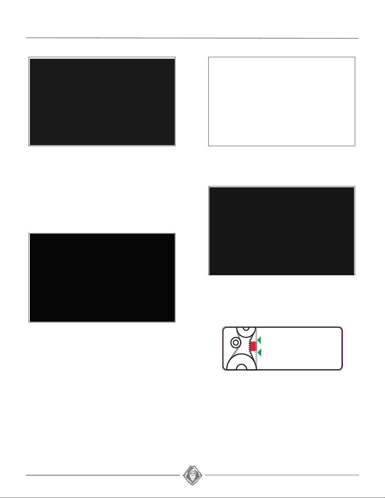
• Recommended setting: Required belt tension
is 11 mm (7/16'') of play, which corresponds to
the width of the red tension gauge in the
tensioner mechanism. See Figure 41.
• Release the automatic chain tensioner back
onto the chain.
SYNCRODRIVE BELT
IMPORTANT: Verify belt tension after 1 or 2
kilometers, and 3 or 4 times on your first outing. If
you notice a significant change in belt tension, readjust tension.
Syncrodrive Belt Tension Verification
• Slide the red tension gauge (1), incorporated in
tensioner mechanism, to the outer edge of the
Syncrodrive belt. See Figure 39.
Figure 41

Syncrodrive Belt Tension Adjustment
FORCE DEFLECTION
6,8 kg (15 lb) 19 mm (¾ in.)
• Loosen tensioner pulley nut (1) ½ to ¾ turn. See
Figure 42.
IMPORTANT: Do not loosen tensioner pulley nut
(1) more than ½ to ¾ turn. If the nut is too loose
during the adjustment process, the belt tension
could increase when the nut is tightened back.
• Loosen lock nut (2) on Belt Tensioner adjusting
bolt. See Figure 42.
YETI SNOWMX USER MANUAL | 20
• Rotate Belt Tensioner adjusting bolt (3) to raise
or lower belt tension. See Figure 41.
Figure 42
• Tighten tensioner pulley nut (1) back to 55 Nm
(38 lb-ft) of torque. See Figure 42.
• Verify tension adjustment. Repeat previous
steps if tension is found insufficient.
TRACK TENSION
CAUTION: The two rear wheel assembly axle nuts
(1) must be loosened before adjusting Track
tension. See Figure 43.
Figure 43
• Rotate the right and left rear wheel axle
adjusting bolts (2) an equal number of turns,
clockwise or counterclockwise, to set the Track
to the recommended tension. See Figure 44.
Figure 44
CAUTION: Use a ruler to verify how long the
adjusting bolts are engaged in the axle. A
misaligned rear axle can cause premature wear of
suspension components.
• The table below shows the force applied and the
deflection which must/ occur when track tension
is correctly set. Refer also to Figure 45.

21 | YETI SNOWMX USER MANUAL
DEFLECTION = 19 mm
[¾ in.]
BASIC TUNING
• A higher rubber track tension reduces drive
“ratcheting”.
NOTE: Track tension set too high could cause
premature wear on system components.
• A lower rubber track tension provides better
traction, a smoother ride and better fuel
economy.
• Check Track tension at mid-point between the
two lower shock absorber mount shafts. Figure
45.
Figure 45
• Tighten the two rear wheel axle nuts (1) back to
55 Nm (38 lb-ft) of torque. Figure 42
NOTE: The track tension testing tool shown below in
Figure 46
Figure 46 can be purchased through an
authorized YETI dealer. The part number is
2000-00-3125.
Final Check
Ride your bike at slow speed on a distance of
about 1.5 km [1 mile]. Re–adjust as required.

YETI SNOWMX USER MANUAL | 22
WARNING
Do not insert hands or feet into or near the
System unless the engine is off, the vehicle is
stopped and the security brake is engaged.
MAINTENANCE
INITIAL INTERVALS
FIRST USE EVERY 8 HRS EVERY 25 HRS EVERY 50 HRS
EVERY 100 HRS /
ANNUAL
SYSTEM - VISUAL INSPECT CLEAN / INSPECT CLEAN / INSPECT CLEAN / INSPECT CLEAN / INSPECT
SYSTEM - ADJUSTMENTS ADJUST CLEAN / INSPECT INSPECT / ADJUST INSPECT / ADJUST
SYSTEM - BOLT TORQUE INSPECT INSPECT / ADJUST
SYSTEM - CHAIN / MASTER LINK ADJUST ADJUST / LUBE CHAIN LUBE MASTER LINK REPLACE MASTER LINK REPLACE CHAIN
SYSTEM - SPROCKETS INSPECT REPLACE
SYSTEM - BRAKE INSPECT INSPECT / ADJUST INSPECT
SYSTEM - CHAIN GUARD
INSPECT INSPECT / REPLACE
SYSTEM - SYNCRO DRIVE BELT
ADJUST INSPECT / ADJUST INSPECT / ADJUST
SYSTEM - BEARINGS, DRIVESHAFT
INSPECT INSPECT / REPLACE
SYSTEM - CRACKS INSPECT
BIKE MOUNT - LUBE INSPECT / LUBE
TRACK- TENSION ADJUST INSPECT / ADJUST INSPECT / ADJUST
TRACK - WEAR INSPECT
WHEELS - WEAR INSPECT
WHEELS - BEARINGS INSPECT INSPECT / REPLACE
SUSPENSION - GUIDE WEAR INSPECT INSPECT
SUSPENSION - LUBRICATION INSPECT / LUBE INSPECT / LUBE
SUSPENSION - NYLON BUSHINGS INSPECT / REPLACE INSPECT / REPLACE
SUSPENSION - SPROCKETS INSPECT
SUSPENSION - RUBBER DAMPER INSPECT INSPECT / REPLACE
SKI - SKAG INSPECT INSPECT / REPLACE
SKI - SIDE RUNNERS INSPECT INSPECT / REPLACE
SKI - RUBBER DAMPER INSPECT INSPECT / REPLACE
SPINDLE - NYLON BUSHINGS INSPECT INSPECT / REPLACE
STRUT ROD - ROD END INSPECT INSPECT / REPLACE
MAINTENANCE
can result in premature wear and important
breakage on the System that will not be covered
under the warranty. The user is responsible to
follow the maintenance schedule provided by the
manufacturer.
The maintenance schedule is provided for optimum
durability of your System. The type and conditions
of usage of the System have a direct bearing on
CAUTION: Regular inspection, adjustment and
lubrication of the System is essential to its good
running order and safe operation. Users have the
responsibility to perform maintenance and regularly
adjust their System. The “Maintenance” section
provides the necessary information to perform
adequate maintenance on the System.
CAUTION: Failure to do regular maintenance at the
prescribed intervals and perform the preventive
adjustments indicated in the maintenance schedule
the frequency of maintenance actions to perform.
After inspection of your System, you will be able to
determine if the recommended maintenance
intervals are correct and adjust them as needed.
For optimum performance and maximum durability,
please refer to the maintenance chart below.
For more details, consult the Maintenance
specifications on page 23 and page 24.

23 | YETI SNOWMX USER MANUAL
MAINTENANCE - TASKS
• Inspect: Component(s) must be examined with
care. If an anomaly is noticed, the
malfunctioning component(s) must be repaired
or replaced.
• Clean
: Component(s) must be cleaned of any
dirt, dust or contaminant liable to impair the
proper operation of the Conversion System.
• Adjust
: Component(s) must be adjusted or readjusted according to the manufacturer’s
adjustment recommendations. Refer to the
relevant section of the User Manual.
• Lubricate
: Component(s) need to be lubricated
according to the manufacturer’s
recommendations. Refer to the relevant section
of the User Manual.
• Replace
: Component(s) must be replaced to
avoid serious breakage.
MAINTENANCE - SPECIFICATIONS
System
• Visual Inspection: Visually inspect the
System’s components to detect any defect or
anomaly that can impair its proper functioning.
• Adjustment
adjustment on the suspension according to the
manufacturer’s recommendations. Refer to the
Adjustments section on page 16.
: Perform or verify angle of attack
• Chain - Wear
: Verify wear and general condition
of chain in drive mechanism. Refer to “Wear” in
the Maintenance section on page 28. Replace
chain if wear is too great.
• Master link - Lubrication
: Remove the chain’s
master link and grease the two pins according to
the maintenance chart recommendations. Refer
to “Lubrication” in the Maintenance section on
page 27.
• Chain - Lubrication
: Lubricate the System’s
drive chain according to the maintenance chart.
Refer to “Lubrication” in the Maintenance section
on page 26.
CAUTION: If a chain needs to be replaced, its
sprockets should be replaced at the same time.
Assembly of new and used parts can speed up wear
of new components installed on drive system.
• Brake Pads - Wear: Verify wear on brake pads.
Refer to “Wear” in the Maintenance section on
page 28. Replace brake pads if wear is too
great.
• Brake - Oil Level
: With the vehicle upright and
on a level surface, check the oil level to make
sure that it is over the indicator mark on the
brake’s master cylinder sight glass. Add oil if
needed.
• Brake - Hydraulic pressure
: Check brake lever
pressure. Bleed brake system if lever feels
spongy or ends its travel too close to the
handlebar. Refer to the Brake Line Bleeding
section on page 14.
• Bolt Torque
: Check the torque of critical bolts
identified in the exploded views of the System.
Refer to the central pages of the User Manual.
CAUTION: Comply with tightening torque
recommendations and use a thread locker product
if you come across a bolt that is not tightened to the
manufacturer’s specifications.
• Chain - Adjustment: Perform or verify tension
adjustment on the System’s drive chain
according to the manufacturer’s
recommendations. Refer to the Adjustments
section on page 18.
• Sprockets - Wear
: Verify wear and general
condition of sprockets in chain drive
mechanism. Refer to “Wear” in the Maintenance
section on page 28. Replace sprockets if wear is
too great.
• Chain Guard - Wear
: Verify wear and general
condition of Chain guard. Refer to “Wear” in the
Maintenance section on page 28.
• Syncro Drive Belt - Wear
: Verify wear and
general condition of Syncro Drive Belt. Refer to
“Wear” in the Maintenance section on page 29.
• Drive Shaft Bearings
: Check Drive Shaft
bearings for restriction, noise or abnormal play in
rotation. Bearings must absolutely be replaced if
they present a defect.
• Cracks
: Visually inspect the System’s frame and
Bike Mount for presence of cracks or defects
that can impair proper operation of the System.
• Bike Mount - Lubrication
: Lube the Bike
Mount’s moving parts. Refer to “Lubrication” in
the Maintenance section on page 27.

YETI SNOWMX USER MANUAL | 24
Track
• Tension: Set or check track tension on the
System according to the manufacturer’s
recommendations. Refer to “Rubber Track
Tension” in the Adjustments section on page 20.
• Wear
CAUTION: A damaged track can result in premature
wear on suspension components.
: Verify wear and overall condition of the
System’s rubber track. Refer to “Wear” in the
Maintenance section on page 29.
Wheels
• Wear: Verify general condition of wheels and
inspect for wear on the outside diameter or
deformation. Refer to “Wear” in the Maintenance
section on page 29. Replace wheel(s) if a defect
is present.
• Bearings
noise or abnormal play in rotation. Replace
wheel bearing if it shows any one of these
defects.
: Check wheel bearings for restriction,
• Rubber Dampers
rubber dampers on suspension rails. Refer to
“Wear” in the Maintenance section on page 30.
Replace dampers if they are severely deformed
or cracked.
: Check general condition of
Ski
• Ski Skag: Inspect general condition of Skag.
Refer to “Wear” in the Maintenance section on
page 31. Replace Skag if it shows signs of
damage or deformation.
• Side Runners
ski’s Side Runners. Refer to “Wear” in the
Maintenance section on page 31. Replace Side
Runners if they show signs too much wear or
deformation.
• Rubber Damper
the Rubber Damper located on the ski. Replace
damper if it is deformed, cracked or shows
severe wear. Refer to “Wear” in the Maintenance
section on page 31.
: Inspect general condition of the
: Inspect general condition of
Strut Rod
Suspension
• Track Guides - Wear: Inspect for wear on
Suspension Guide rails. Refer to “Wear” in the
Maintenance section on page 30. Replace guide
rails if wear is too great.
• Front Suspension Arm - Lubrication
the front suspension arm’s upper pivot shaft and
lower nylon bushings as per the maintenance
chart. Refer to “Lubrication” in the Maintenance
section on page 26.
• Shock Absorbers Upper & Lower Mounting
Points - Lubrication: Lube the shock
absorbers’ upper and lower mounting points as
per the maintenance chart. Refer to
“Lubrication” in the Maintenance section on
page 26.
• Nylon Bushings - Wear
of wear of nylon bushings on front and rear
suspension arm. Refer to “Wear” in the
Maintenance section page 30. Replace
bushings if play or wear is too great.
: Verify play and extent
: Lube
• Rod End: Check the Strut Rod’s rod end for
wear or excessive play. Refer to “Wear” in the
Maintenance section on page 31. Replace rod
end if it shows one of these defects.
Spindle
• Nylon Bushings - Wear: Verify play and extent
of wear of nylon bushings on bolt securing ski to
spindle. Refer to “Wear” in the Maintenance
section on page 32. Replace bushings if play or
wear is too great.
• Drive Sprockets - Wear
the sprockets driving the rubber track. Refer to
“Wear” in the Maintenance section on page 29.
Replace the sprockets if wear is too great.
: Inspect for wear on

25 | YETI SNOWMX USER MANUAL
A Front suspension arm - Upper shaft
B Shock absorbers - Lower shaft
C Rear shock absorber - Upper shaft
D Adjustment bolts - Rear axle
E Front suspension arm - Lwr bushings
F Circular slots - Eccentric cam
G Slots - T-nuts
H Adjustment bolt - Belt tensioner
i
Chain & Master link
LUBRICATION

YETI SNOWMX USER MANUAL | 26
LUBRICATION
The maintenance chart on page 22 contains
lubrication maintenance to be performed on the
System. Refer to the following
recommendations for optimal lubrication.
NOTE: Use a good quality translucent synthetic grease.
NOTE: Components might have to be removed to
access some of the lubrication points.
REFERENCE “A”
FRONT SUSPENSION ARM - UPPER SHAFT
Apply 3-4 cc of grease evenly all around and over
the entire length of the front suspension arm’s
upper shaft (A).
REFERENCE “C”
REAR SHOCK ABSORBER - UPPER MOUNT
Apply 1-2 cc of grease evenly around mid-point of
rear shock absorber’s upper support shaft (C).
REFERENCE “D”
CHAINS
Apply 1 cc of grease on threads of track tension
adjustment bolts (D).
REFERENCE “B”
SHOCK ABSORBERS - LOWER SHAFT
Apply 1-2 cc of grease evenly all around the midpoint of the shock absorbers’ lower support shafts
(B).
REFERENCE “E”
FRONT SUSPENSION ARM - LOWER MOUNTS
Apply 1-2 cc of grease evenly around front
suspension arm’s lower bushings (E).

27 | YETI SNOWMX USER MANUAL
REFERENCE “F”
ECCENTRIC CAM - SLOTS
Apply 1-2 cc of grease to circular slots (F) on each
side of Bike Mount eccentric cam.
REFERENCE “H”
SYNCRO DRIVE BELT - TENSION
ADJUSTMENT BOLT
Apply 1 cc of grease to threads of belt tension
adjustment bolt (H).
REFERENCE “i”
REFERENCE “G”
T-NUTS - SLOTS
Apply 1 cc of grease to Bike Mount T-slots (G).
CHAIN & MASTER LINK
Spray grease on the System’s drive chain (i).
Remove master link from primary chain and apply
a small quantity of grease to the link’s pins.

YETI SNOWMX USER MANUAL | 28
REPLACE
WEAR
Chain Drive Sprockets
Inspect the chain drive sprockets (A) for wear. If
the chain is set to the required tension (3-6 mm [1/
8-1/4 in.] deflection) but misses or skips over some
of the driving teeth, the sprockets must be
replaced. See Figure 47.
CAUTION: If a chain is replaced, the sprockets
should be replaced at the same time. Assembly of
new and used parts can speed up wear of the new
components installed on the drive system.
Check wear on the primary chain’s master link
pins. If abnormal wear is present, replace the
master link. See Figure 49.
Figure 49
Brake pads
Inspect brake pads (A) for wear. If pad thickness is
under 1.6 mm (1/16 in.), replace the parts. See
Figure 50.
Figure 47
Chain
If the chain is adjusted to the highest tension
setting (A) and the required 3 - 6 mm amount of
play (1/8-1/4 in.) cannot be obtained at mid-point
(B) between the sprockets, the chain should be
replaced. See Figure 48.
Figure 48
CAUTION: If the chain is replaced, the sprockets
should be replaced at the same time. Assembly of
new and used parts can speed up wear of the new
components installed on the drive system.
Figure 50
Chain guard
Verify wear on Chain guard (A). Replace guard if
wear reaches the part number molded at the front.
See Figure 51.
Figure 51

29 | YETI SNOWMX USER MANUAL
Chain guard spring
Verify that the Chain guard spring (A) is functional
and not damaged. Replace if defective. Figure 52.
Figure 52
Syncro Drive belt
Check the general condition of the Syncro Drive
belt (A). If you notice cracks or missing teeth, if
cord is showing or there is abnormal wear, replace
the belt. Figure 53.
CAUTION: Verify Jack Shaft alignment if repeated
wear problems occur on the belt.
Track
Verify wear on Track by inspecting the internal (A)
and external (B) condition of the Track's carcass
C
rolling path, driving lugs (
), the profile (D). Make
sure that the Track’s internal structure is not visible
at cuts or in worn areas. Make sure the steel clips (
E
are not abnormally worn. See Figure 54.
Figure 54
Wheels
Verify the general condition of wheels. If they show
important wear or missing fragments, replace the
wheel. Check wheel bearings for restriction, noise
or abnormal play in rotation. Replace wheel or
wheel bearing if they present any one of these
defects. Figure 55.
)
Figure 53
Track Drive Sprockets
Inspect the Sprockets that drive the Track. If the
Track is set to the required tension (19 mm
deflection for an applied force of 6.8 kg) and that
the sprockets miss or skip over some of the driving
lugs, the sprockets must be replaced.
Figure 55

YETI SNOWMX USER MANUAL | 30
Track Guides
Inspect the Track Guides for wear. If a guide is less
than 15 mm thick (22 mm - when new), anywhere
along the entire length, replace the part.
Figure 56
Figure 56
Verify if the guide is thick enough to cover the
assembly bolt head at the front. Thickness should
be over 20 mm. See Figure 57.
See
NOTE: YETI 120SS or 129SS shown.
OWER FRONT ARM NYLON BUSHINGS
L
UPPER FRONT ARM NYLON BUSHINGS
Figure 58
Figure 57
Nylon bushings - suspension
Verify play and extent of wear on the suspension’s
nylon bushings (A). If there is abnormal play in the
bushings, replace them. See Figure 58, Figure 59
and Figure 60.
Figure 59
UPPER REAR ARM NYLON BUSHINGS
Figure 60
Rubber Dampers (suspension)
Verify general condition of rubber dampers installed
on the suspension rails.
replaced if they show cracks or are excessively
worn or deformed
. See Figure 61.
The dampers should be

31 | YETI SNOWMX USER MANUAL
Figure 61
Ski Skag
If the ski lacks support through turns on ice, check
condition of the skag (A). If the blades (B) show
deformations or are less than 4mm in height (8mm
when new), they do not provide enough support.
The skag should be replaced. See Figure 62.
Rubber Damper (ski)
Inspect Rubber Damper mounted on ski. Replace
damper if it shows cracks or is excessively worn or
deformed. A deformed Rubber Damper does not
provide adequate support to the ski and affects the
bike’s steering behavior. See Figure 64.
Figure 64
CAUTION: Rubber damper must be correctly seated
in position. An improperly seated rubber damper
can result in ice accumulating underneath and
difficult steering.
Figure 62
Side Runners
Verify the Side runners (A) mounted on the ski. If
they show rounded edges, they should be resharpened. Replace part if the height of a runner is
under 19 mm (25mm when new). See Figure 63.
Ball Joint - Strut Rod
Inspect ball joint on Strut rod. Make sure that it is
not seized or too loose. Figure 65.
CAUTION: A damaged ball joint can make the System
difficult to adjust and result in damages if not
replaced.
Figure 65
Figure 63

Nylon bushings - Ski & Spindle assembly
Verify play and extent of wear on the nylon
bushings (A) guiding the assembly bolt that
secures the ski to the spindle. If there is abnormal
play in the bushings, replace them. See Figure 66.
Figure 66
YETI SNOWMX USER MANUAL | 32

33 | YETI SNOWMX USER MANUAL
2-YEAR LIMITED WARRANTY
Camso guarantees that the new, unused YETI
SNOWMX System (System) installed by an
authorized dealer or distributor is free from any
defects in materials and workmanship during the
period and in conditions described below. When
operating a new YETI SNOWMX System, the user
agrees that the present form is applicable and
exclusive, that they have been signified and that
they have been accepted by him/her at the time of
purchase.
The YETI SNOWMX Dirt-To-Snow bike conversion
System is covered by a manufacturer warranty
(warranty). The warranty covers manufacturing
defects related with materials and workmanship.
The installation and maintenance of the System is
always the responsibility of the owner.
PERIOD OF COVERAGE
The warranty is valid for a period of twenty-four
(24) months following the date of purchase. This
warranty does not apply to normal maintenance.
The warranty applies exclusively to parts and
components of the conversion System. All paint
defects on the System (frames and components)
are not covered.
The warranty is not valid if the System is not
installed by an authorized YETI network dealer or
distributor.
This warranty specifically excludes any damage or
breakage to the motorcycle and related defects on
the motorcycle, whether or not these were caused
or believed to be caused by the System.
The manufacturer is not responsible for damages,
injuries or loss caused at the time of or after
installing of the System on the motorcycle.
For a warranty to be valid, the System owner must
comply with manufacturer notices and warnings. In
addition, all claims must be accompanied by a
proof of purchase (original receipt or sale contract)
and work or repairs must be performed by an
authorized YETI dealer. All claims not previously
approved and authorized by Camso will be
rejected.
The following situations and items are not
under any circumstances covered by the
warranty:
1) Any and all consequential damages, including,
but not limited to, indirect costs, such as towing,
storage, phone calls, renting, transportation,
inconveniences, insurance coverage,
reimbursement of loss, loss of time and loss of
revenue, etc.
2) Damage resulting from faulty installation.
3) Damage resulting from normal parts wear or
progressive deterioration owing to the distance
covered with a vehicle on which the System is
installed.
4) Damage resulting in non-compliance with the
user manual and with maintenance instructions
recommended in the user’s manual and other
technical documents.
5) Damage resulting in abusive use, abnormal use,
negligence or even a use which does not comply
with recommendations of the manual, excess
weight or loading, including excessive number of
passengers.
6) Labor costs, parts and materials related any and
all maintenance costs.
7) Damage resulting from faulty repairs, improper
maintenance or any unauthorized changes made
to the System other than those specified by the
manufacturer or from the installation of non-original
or unauthorized parts that were not produced or
approved by Camso.
8) Damage resulting from an accident, incident,
robbery, vandalism, war or unforeseen event or act
of God.
9) Regardless of cause, damage resulting from
inexperience, driving errors, accident or other
incident.
10) The use of the System on a motorcycle used
for public rental, including by a previous owner, will
render this warranty null and void.
11) The use of the System in races, rallies or other
competitive events/activities of this type, at any
time, including from a previous owner or in
conditions that do not comply with those described
by the manufacturer will render the warranty null
and void.

YETI SNOWMX USER MANUAL | 34
Any repaired or replaced components or parts are
guaranteed only to the extent of the original
warranty. in other words: if a warranted part was
replaced after nine (9) months, the new
replacement part will only be guaranteed for fifteen
(15) months, for a total of twenty–four (24) months.
Any claim for a track will be established according
to its residual value, 100% during the first 12
months, 75% between 12 and 18 months and 50%
between 18 and 24 months. The residual value will
have to be applied in the form of reduction to the
purchase of a track of replacement at regular
price. In no event shall the warranty extend
beyond a total of twenty-four (24) months from the
date of original System purchase.
In all cases, the warranty is limited to a maximum
of the original purchase price or the fair market
value of the System. Camso will have final
authority in determining the fair market value of a
used System. The warranty is applicable within the
limits and conditions initially contracted. If the
System is determined to be unusable due to
accident or improper repair, the warranty will be
considered null and void without further recourse
available to the System owner.
The manufacturer, the retailer and/or the repair
shop shall not be held responsible for any delays
caused by material, parts or components
availability or backorder.
*Shipping and handling costs, as well as any fees
related with shipping or transportation of the
System to the dealer location are the responsibility
of the System owner.
ELKASHOCKS
CANADA:
ELKA FACTORY SERVICE DEPT
1585-M De Coulomb, Boucherville, Québec,
Canada J4B 8J7
Phone: 1-800-557-0552
U.S.A:
IMPACT SOLUTIONS LLC.
655 Hocking Rd., Little Hocking, OH 45742
Phone: 740-989-2026
www.impactsolutionsatv.com
www.elkasuspension.com
Camso reserves its sole and exclusive right to
update or modify this warranty without impact on
end users. All previous terms and conditions of the
warranty at time of purchase will be respected.
SHOCK ABSORBERS
Camso guarantees that the ELKA shock absorbers
are free from any defects in materials and
workmanship during a period of twelve (12)
months. All subsequent support, maintenance or
repair requests should be sent to the appropriate
ELKA Authorized Service Center.

35 | YETI SNOWMX USER MANUAL
PROBLEM CAUSE SOLUTION
Unstable ski / handling too loose
Incorrect angle of attack adjustment Re-adjust the suspension’s angle of attack
Ski mount is iced up & does not move
Break any ice under the front or back of the
upright (around rubber location) check if ski
can move 15-20° up and 5-10° down
Suspension preload too high Lower spring preload
Broken Suspension Limiter Strap Replace Limiter Strap
Limiter Strap is adjusted to long position Adjust Limiter Strap to a shorter position
Ski washout / Understeering
Sagged, damaged ski damper
Replace Ski damper if ski can move more
than 20° up or 10° down
Compound too soft Replace rubber damper on ski
Ice build-up
Break any ice under the front or back of the
upright (around rubber location) check if ski
can move 15-20° up and 5-10° down
Limiter Strap is adjusted to long position Adjust Limiter Strap to a shorter position
Ratcheting
Track too loose, worn sprockets, worn track
Adjust track tension, inspect parts, replace if
needed
Chain tensioner not adjusted properly or
sprockets worn out
Adjust chain tension. Inspect parts, replace if
needed
Chain or chain sprockets rapidly worn
out
Improper chain adjustment or too little
lubrication
Replace parts as a set, adjust & lubricate to
manual specification (frequency)
Misalignment of track drive shaft
Verify and realign drive track drive shaft
assembly
Rattling sound coming from rear of kit
Skin cover incorrectly installed
Verify if cover is properly seated, skin cover
must be inserted in the side panel openings
Top idler wheel bearing worn Replace top idler wheel or bearing
TROUBLESHOOTING

YETI SNOWMX USER MANUAL | 36
PROBLEM CAUSE SOLUTION
Suspension does not collapse or travel Humidity has iced up inside shock absorber
Shock absorber needs to be replaced or
taken off for maintenance
Understeering on icy terrain Side runner worn out Re-sharpen or replace
Hard to initiate leaning Slide is worn out Replace slide
Brake needs to be pumped in order to
brake (spongy brake lever)
Disc brake is bent or loose
Replace damaged parts. Check torque on
brake hub.
Excessive ice build-up on disc
Pay attention to ice build-up in particular
conditions
Air trapped in brake line Bleed braking system
Brake system is hard to bleed Improper brake line routing
Brake line must be routed as straight as
possible. Avoid small radius bends
Hissing sound when applying brake Brake pads are loose or worn out Verify installation or replace pads
Bike hard to start (too rich)
Air temperature sensor trapped in snow
(permanent cold start mode)
Relocate Air temperature sensor or install
pre-filter on sensor

37 | YETI SNOWMX USER MANUAL
B
C
A
ITEM
PART # DESCRIPTION QTY
YETI SNOWMX MY2020 :: JACKSHAFT / BEARING TOOL KIT
A YAAC1946 TOOL KIT, JACK SHAFT / BEARING TOOL KIT 1
B YAAC1785 TOOL, BEARING PULLER ASSEMBLY 1
1 YPAC1232 TOOL, PLATE SHAFT REMOVAL - CLEAR 1
2 YPAC1234 TOOL, SHAFT REMOVAL - ZINC 1
3 YPAC1850 TOOL, BEATING PULL PLATE 1
4 YPHW1570 W, 20X10X2.0MM, YZ, DIN125 1
5 YPHW2411 TRUST NEEDLE BEARING, 5/16X3/4X5/64 1
6 YPHW2415 WASHER, 0.734X0.250, ZP 1
7 YPHW2416 HCS,M5-0.8X10MM, ZP, FULL THREAD 1
8 1033-08-0100 HCS, M8-1.25X100, 8.8, ZP, DIN931 2
9 1033-08-1060 HCS, M8-1.25X60, 10.9, ZP, DIN931 3
C YAAC1945 TOOL, SHAFT INSTALL TOOL ASSEMBLY 1
1 YPHW1936 INSTALLATION TOOL, COLLAR SCH 40 1
2 YPHW1942 HCS, M12-1.25X60MM, 8.8, ZP 1
3 YPHW1943 FW, 0.531X1.50X0.125, ZP 1
4 1073-12-3001 HN, M12-1.25, 8, ZP 1
TOOLING LIST

YETI SNOWMX USER MANUAL | 38
1
ITEM
PART # DESCRIPTION QTY
YETI SNOWMX MY2020 :: BIKE MOUNT INSTALLATION TOOL
1 YAAC1986 TOOL, BIKE MOUNT INSTALLATION 2.1 - 2.2 1
2 YPAC1968 TOOL, BUSHING, BIKE MOUNT ADAPTOR 1
3 YPHW1688 HN, M8-1.25, 8, ZP 1
4 YPHW1978 FW,5/16 - M9 2
5 1033-08-0150 HCS, M8-1.25X150, 8.8, ZP, DIN933 1
1
ITEM
PART # DESCRIPTION QTY
YETI SNOWMX MY2020 :: BELT ALIGNMENT JIG
1 YAAC3000 BELT ALIGNMENT JIG - YETI 1
2 YPAC3001 BELT ALIGNMENT TOOL - YETI 1
3 YPHW1942 HCS, M12-1.25X60MM, 8.8, ZP 2

39 | YETI SNOWMX USER MANUAL
10 Nm
1
TORQUE
THREAD LOCKER
10 Nm
55 Nm
25 Nm
5 Nm
10 Nm
PARTS LIST
SKI ASSEMBLY

YETI SNOWMX USER MANUAL | 40
ITEM
PART # DESCRIPTION QTY
YETI SNOWMX MY2020 :: SKI ASSEMBLY
1-A YASK2005BK SKI ASSEMBLY, YETI - BLACK 1
1-B YASK2005BL SKI ASSEMBLY, YETI - BLUE 1
1-C YASK2005GN SKI ASSEMBLY, YETI - GREEN 1
1-D YASK2005OR SKI ASSEMBLY, YETI - ORANGE 1
1-E YASK2005RD SKI ASSEMBLY, YETI - RED 1
1-F YASK2005WT SKI ASSEMBLY, YETI - WHITE 1
2 YPHW1030 HFCS, M6-1.0X55MM, TI 2
3 YPHW1059 SLN, M10-1.25, TI 1
4 YPHW1063 FNLN, M6-1.0, TI 2
5 YPHW1599 HFCS, M10-1.25X110, TI 1
6 YPHW2628 HFCS, M8-1.25X16, TI 2
7 YPSK1171 BUMPER RUBBER SKI, YETI ASM 1
8 YPSK1172 BUSHING ASM, SKI PIVOT - HARD ANODIZED 1
9-A YPSK1195BK SKI HANDLE - BLACK 1
9-B YPSK1195BL SKI HANDLE - BLUE 1
9-C YPSK1195GN SKI HANDLE - GREEN 1
9-D YPSK1195OR SKI HANDLE - ORANGE 1
9-E YPSK1195RD SKI HANDLE - RED 1
9-F YPSK1195WT SKI HANDLE - WHITE 1
10 YPSK1823 SKI, OUTSIDE RUNNER 2
11 YPSK1904 PLATE, SKI BUMPER, TI 1
12 YPSK2448CL SKI RECEIVER, LIGHTEND - CLEAR 1
13-A YPSK3002BK SKI, BOARD - BLACK 1
13-B YPSK3002BL SKI, BOARD - BLUE 1
13-C YPSK3002GN SKI, BOARD - GREEN 1
13-D YPSK3002OR SKI, BOARD - ORANGE 1
13-E YPSK3002RD SKI, BOARD - RED 1
13-F YPSK3002WT SKI, BOARD - WHITE 1
14 YPSK3003 SKAG 1
15 YPSK3031 SKAG WASHER 1
16 1074-08-0001 FNN, M8-1.25, 8, ZP, DIN6926 3
17 1430-06-X016 RWHS, 6X16, TX, ZP 4

41 | YETI SNOWMX USER MANUAL
TORQUE
THREAD LOCKER
25 Nm
25 Nm
9 Nm
A
25 Nm
25 Nm
SPINDLE ASSEMBLY

YETI SNOWMX USER MANUAL | 42
ITEM
PART # DESCRIPTION QTY
YETI SNOWMX MY2020 :: SPINDLE ASSEMBLY
1 YPHW2628 HFCS, M8-1.25X16MM, TI 16
2 YPHW1008 HSCS, M8-1.25X25MM, TI 4
3 YPHW1009 HSCS, M8-1.25X20MM, TI 2
4 YPHW1376 HFCS, M8-1.25X43MM, TI 2
5 YPHW1594 HSCS, M6-1.0X30MM, TI 2
6 YPHW1611 PLAIN BEARING, IGLIDE, 18X16X17 2
7 YPSP1028CL SPINDLE FORK CLAMP SPACER 190MM - CLEAR 1
8 YPSP1079CL SPINDLE BLADE SPACER - CLEAR 1
9 YPSP1430CL SPINDLE HALF BLOCK, BLADE 1/4'' - CLEAR 2
10 YPSP2400 SPINDLE BLADE, OUTSIDE, 14.5 2
11 YPSP2511 BEARING SLEEVE Q2 2
BIKE SPECIFIC SPINDLE ASSEMBLY PARTS
* SEE YETISNOWMX.CA/YETIVERTER *
A -- SPINDLE ASSEMBLY 1
B -- SPINDLE FORK CLAMP CAP, LH - CLEAR 1
C -- SPINDLE FORK CLAMP CAP, RH - CLEAR 1
D -- SPINDLE AXLE SPACER, LH - CLEAR 1
E -- SPINDLE AXLE SPACER, RH - CLEAR 1
F -- SPINDLE FORK CLAMP LH - CLEAR 1
G -- SPINDLE FORK CLAMP RH - CLEAR 1
H -- SPINDLE BLADE, CENTER, 14.5 1
OPTIONAL
i YPSP3054 SPACER, SPINDLE 2

43 | YETI SNOWMX USER MANUAL
3
1
18
TORQUE
THREAD LOCKER
5 Nm
5 Nm
5 Nm
CHASSIS ASSEMBLY - 129FR & 137MT

YETI SNOWMX USER MANUAL | 44
ITEM
PART # DESCRIPTION QTY
YETI SNOWMX MY2020 :: CHASSIS ASSEMBLY - 129FR & 137MT
1 YACH3929 CHASSIS ASSEMBLY 1
2 YPCH1107CL SYNCRODRIVE COVER - CLEAR 1
3-A YADC3180BK DECAL, YETI SNOWMX 2020, BLACK 1
3-B YADC3180BL DECAL, YETI SNOWMX 2020, BLUE 1
3-C YADC3180GN DECAL, YETI SNOWMX 2020, GREEN 1
3-D YADC3180OR DECAL, YETI SNOWMX 2020, ORANGE 1
3-E YADC3180RD DECAL, YETI SNOWMX 2020, RED 1
3-F YADC3180WT DECAL, YETI SNOWMX 2020, WHITE 1
4 YPCH1175BK BUMPER, FORMED PLATE - BLACK 1
5 YPCH1176 BUMPER, MOLDED HANDLE 1
6-A YPCH1179BK BUMPER, YETI INSERT - BLACK 1
6-B YPCH1179BL BUMPER, YETI INSERT - BLUE 1
6-C YPCH1179GN BUMPER, YETI INSERT - GREEN 1
6-D YPCH1179OR BUMPER, YETI INSERT - ORANGE 1
6-E YPCH1179RD BUMPER, YETI INSERT - RED 1
6-F YPCH1179WT BUMPER, YETI INSERT - WHITE 1
7 YPCH1578 CHAIN SLIDER 1
8 YPCH1618 DEFLECTOR DAMPENER, SILICONE 1
9 YPCH1643 DECAL, SYNCRODRIVE DEFLECTION 1
10 YPCH1776 BELT DEFLECTOR, SYNCRODRIVE 1
11 YPCH1925 NUT PLATE, BUMPER, LH 1
12 YPCH1926 NUT PLATE, BUMPER, RH 1
13 YPCH2553 SUSPENSION MOUNT PLATE, FRONT M10 2
14 YPCH2554 SUSPENSION MOUNT PLATE, REAR M10 2
15 YPCH3105 BRAKE LINE PROTECTOR 1
16 -- STICKER - SERIAL MY2020 1
17 YPHW1348 1/4 TURN RECEPTACLE 4
18 YPHW1573 HSBS, M5-0.8X12MM, 10.9, SS 26
19 YPHW1586 1/4 TURN FASTENER PUSH ON RETAINER S/S 4
20 YPHW1598 RN, M5-0.8X9.4MM, ZP 2
21 YPHW1676 1/4 TURN FASTENER, 27MM 4
22 YPHW1769 HSLS, M5-0.8X16MM, TI 6
23 YPHW2578 RIVET, 3/16", SS 16
24 YPHW3190 WEATHERSTRIP RETAINER 4
25 1083-00-0067 STICKER - DO NOT LOOSEN 1
26 1083-00-8302 STICKER - WARNING 1

45 | YETI SNOWMX USER MANUAL
3
1
TORQUE
THREAD LOCKER
5 Nm
5 Nm
5 Nm
CHASSIS ASSEMBLY - 120SS

YETI SNOWMX USER MANUAL | 46
ITEM
PART # DESCRIPTION QTY
YETI SNOWMX MY2020 :: CHASSIS ASSEMBLY - 120SS
1 YACH3921 CHASSIS ASSEMBLY 120SS 1
2 YPCH1107CL SYNCRODRIVE COVER - CLEAR 1
3-A YADC3180BK DECAL, YETI SNOWMX 2020, BLACK 1
3-B YADC3180BL DECAL, YETI SNOWMX 2020, BLUE 1
3-C YADC3180GN DECAL, YETI SNOWMX 2020, GREEN 1
3-D YADC3180OR DECAL, YETI SNOWMX 2020, ORANGE 1
3-E YADC3180RD DECAL, YETI SNOWMX 2020, RED 1
3-F YADC3180WT DECAL, YETI SNOWMX 2020, WHITE 1
4 YPCH1578 CHAIN SLIDER 1
5 YPCH1618 DEFLECTOR DAMPENER, SILICONE 1
6 YPCH1643 DECAL, SYNCRODRIVE DEFLECTION 1
7 YPCH1776SS BELT DEFLECTOR, SYNCRODRIVE SS 1
8 YPCH2553 SUSPENSION MOUNT PLATE, FRONT M10 2
9 YPCH2554 SUSPENSION MOUNT PLATE, REAR M10 2
10 YPCH3105 BRAKE LINE PROTECTOR 1
11 YPCH3163 BUMPER, FORMED PLATE 1
12 YPCH3164 BUMPER, LEFT HANDLE 1
13 YPCH3165 BUMPER, RIGHT HANDLE 1
14 YPCH3166 NUT PLATE, BUMPER ASSY 1
15 -- STICKER - SERIAL MY2020 1
16 YPDC3144 BUMPER, YETI INSERT 1
17 YPHW1348 1/4 TURN RECEPTACLE 4
18 YPHW1573 HSBS, M5-0.8X12MM, 10.9, SS 16
19 YPHW1586 1/4 TURN FASTENER PUSH ON RETAINER S/S 4
20 YPHW1598 RN, M5-0.8X9.4MM, ZP 2
21 YPHW1676 1/4 TURN FASTENER, 27MM 4
22 YPHW1769 HSLS, M5-0.8X16MM, TI 6
23 YPHW2578 RIVET, 3/16", SS 16
24 YPHW3190 WEATHERSTRIP RETAINER 4
25 1083-00-0067 STICKER - DO NOT LOOSEN 1
26 1083-00-8302 STICKER - WARNING 1

47 | YETI SNOWMX USER MANUAL
41 Nm
1
9 Nm
TORQUE
THREAD LOCKER
25 Nm
61 Nm
25 Nm
25 Nm
20
BIKE MOUNT ASSEMBLY - YETI 129FR & 137MT

YETI SNOWMX USER MANUAL | 48
ITEM
PART # DESCRIPTION QTY
YETI SNOWMX MY2020 :: BIKE MOUNT ASSEMBLY 129FR & 137MT
1 -- BIKE MOUNT ASSEMBLY 1
2 YPBM1108CL CROSS BAR, TUNNEL SIDE PLATE - CLEAR 2
3 YPBM1137CL ECCENTRIC CAM - CLEAR 1
4 YPBM1593 FN, M16-1.5, TI 1
5 YPBM1831CL TUNNEL SIDE PLATE 2.2, LH - CLEAR 1
6 YPBM1833BK BIKE MOUNT PLATE, LH, 2.2 10MM - BLACK 1
7 YPBM1834BK BIKE MOUNT PLATE, RH, 2.2 10MM - BLACK 1
8 YPBM1880BK STRUT MOUNT BLOC M10 - BLACK 1
9 YPBM1920 NUT PLATE, CROSS BAR 2
10 YPBM1924 NUT PLATE, TUNNEL PLATE, RH 1
11 YPBM3157 TUNNEL SIDE PLATE, RH 1
12 YPDR1130CL BOLT, ECCENTRIC CAM - CLEAR 1
13 YPHW1001 HFCS, M8-1.25X20MM, TI 2
14 YPHW1008 HSCS, M8-1.25X25MM, TI 2
15 YPHW1009 HSCS, M8-1.25X20MM, TI 2
16 YPHW1012 HSCS, M6-1.0X25MM, TI 2
17 YPHW1035 HFCS, M10-1.25X95MM, TI 1
18 YPHW1129 TN, M8-1.25, TI 2
19 YPHW1712 DP, 3/16” - 5/8”, ALLOY STEEL 2
20 YPHW1895 HFCS, M10-1.25X32MM, TI 3
21 YPHW1897 HFCS, M8-1.25X25MM, TI 3
22 YPHW2628 HFCS, M8-1.25X16, TI 4

49 | YETI SNOWMX USER MANUAL
1
20
TORQUE
THREAD LOCKER
9 Nm
25 Nm
25 Nm
25 Nm
41 Nm
61 Nm
BIKE MOUNT ASSEMBLY - YETI 120SS

YETI SNOWMX USER MANUAL | 50
ITEM
PART # DESCRIPTION QTY
YETI SNOWMX MY2020 :: BIKE MOUNT ASSEMBLY 120SS
1 -- BIKE MOUNT ASSEMBLY 120SS 1
2 YPBM1137CL ECCENTRIC CAM - CLEAR 1
3 YPBM1593 FN, M16-1.5, TI 1
4 YPBM1833BK BIKE MOUNT PLATE, LH, 2.2 10MM - BLACK 1
5 YPBM1834BK BIKE MOUNT PLATE, RH, 2.2 10MM - BLACK 1
6 YPBM1880BK STRUT MOUNT BLOC M10 - BLACK 1
7 YPBM1920 NUT PLATE, CROSS BAR 2
8 YPBM1924 NUT PLATE, TUNNEL PLATE, RH 1
9 YPBM3121 PLATE, TUNNEL SIDE HD, LH 1
10 YPBM3123 PLATE, TUNNEL SIDE HD, RH 1
11 YPBM3139 CROSS BAR, TUNNEL SIDE PLATE - CLEAR 2
12 YPDR1130CL BOLT, ECCENTRIC CAM - CLEAR 1
13 YPHW1001 HFCS, M8-1.25X20MM, TI 2
14 YPHW1012 HSCS, M6-1.0X25MM, TI 2
15 YPHW1035 HFCS, M10-1.25X95MM, TI 1
16 YPHW1129 TN, M8-1.25, TI 2
17 YPHW1712 DP, 3/16” - 5/8”, ALLOY STEEL 2
18 YPHW1895 HFCS, M10-1.25X32MM, TI 3
19 YPHW1897 HFCS, M8-1.25X25MM, TI 7
20 YPHW2628 HFCS, M8-1.25X16, TI 4

51 | YETI SNOWMX USER MANUAL
1
129FR
137MT
120SS
Apply Loctite 648 to splines
TORQUE
THREAD LOCKER
25 Nm
25 Nm
61 Nm
61 Nm
JACK SHAFT ASSEMBLY

YETI SNOWMX USER MANUAL | 52
ITEM
PART # DESCRIPTION QTY
YETI SNOWMX MY2020 :: JACK SHAFT ASSEMBLY
1-A -- JACK SHAFT ASSEMBLY, 129FR & 137MT 1
1-B -- JACK SHAFT ASSEMBLY, 120SS 1
2 YPDR1051BK BEARING HOLDER JACK SHAFT - BLACK 1
3 YPDR1259 6304 BEARING 1
4 YPDR1260 6205 BEARING 1
5-A YPDR1724 SPROCKET, 16T, KTM SPLINE -- (129FR &137MT) 1
5-B YPDR2402 SPROCKET, 14T, 25.2MM X 15 SPLINE -- (120SS) 1
6 YPDR1818 NUT PLATE, DRIVE PLATE 1
7 YPDR1923 NUT PLATE, TUNNEL PLATE LH 1
8-A YPDR2060 JACK SHAFT, TI 1
8-B YPDR2362 JACK SHAFT SS, TI 1
9 YPDR2110 COVER, TENSIONER BOLT 1
10 YPDR3001 BEARING HOUSING, ADJUSTABLE 1
11 YPDR3002 ANGLE 2
12 YPHW1034 HFCS, M12-1.25X20MM, TI 2
13 1049-08-1020 HSFS, M8-1.25X20MM, TI 7
14 YPHW1057 W, 1.50X1.0X0.125, SS 1
15 YPHW1282 IRR, 2.00'' 1
16 YPHW1657 ERR, 1.00" (#100) 2
17 YPHW1897 HFCS, M8-1.25X25MM, TI 4

53 | YETI SNOWMX USER MANUAL
TORQUE
THREAD LOCKER
1
25 Nm
14 Nm
25
Nm
61
Nm
25
Apply Loctite 660 to splines
33 Nm
DRIVE SHAFT ASSEMBLY - YETI 129FR & 137MT

YETI SNOWMX USER MANUAL | 54
ITEM
PART # DESCRIPTION QTY
YETI SNOWMX MY2020 :: DRIVE SHAFT ASSEMBLY - 129FR & 137MT
1 -- DRIVE SHAFT ASSEMBLY, STD 1
2 YPDR1049BK BEARING HOLDER, DRIVE SHAFT, LH - BLACK 1
3 YPDR1259 6304 BEARING 1
4 YPDR1260 6205 BEARING 1
5 YPDR1893 DRIVE SHAFT, 1 1/16" HEX, TI 1
6 YPDR2109CL NUT PLATE, DRIVE - CLEAR 1
7 YPDR3003 SPROCKET 7T, 2.86 PITCH, INT/EXT 2
8 YPDR3108 BRAKE SIDE OUTER PLATE 1
9 YPDR3109 BRAKE ROTOR 1
10 YPDR3111 FOAM RUBBER BRAKE SHIELD 1
11 YPDR3118 FOAM RUBBER BRAKE SHIELD 1
12 YPDR3124 ROTOR HUB 1
13 YPDR3127 BRAKE CARRIER 1
14 YPDR3128 OUTER BRAKE SHIELD, COVER 1
15 YPDR3134 BRAKE SHIELD 1
16 YPHW1034 HFCS, M12-1.25X20MM, TI 2
17 YPHW1057 W, 1.50X1.0X0.125, SS 1
18 YPHW1282 IRR, 2.00'' 2
19 YPHW3127 ERR, 1-1/16'' (INVERTED) 2
20 1035-06-A016 HFCS, M6-1.0X16MM, 10.9, ZP, TL, IFI536 6
21 1035-08-A070 HFCS, M8-1.25X70, 10.9, ZP, TL, IFI536 2
22 1049-08-1020 HSFS, M8-1.25X20MM, TI 4
23 1049-08-1040 HSFS, M8-1.25X40, 10.9, ZP, DIN7991 4
24 1051-00-9063 SPACER, BRAKE SHIELD 2
25 1086-00-9073 BRAKE, SYSTEM ASSY, 78'' 1

55 | YETI SNOWMX USER MANUAL
1
25 Nm
41 Nm
61 Nm
25 Nm
14 Nm
Apply Loctite 660 to splines
TORQUE
THREAD LOCKER
8
DRIVE SHAFT ASSEMBLY - YETI 120SS

YETI SNOWMX USER MANUAL | 56
ITEM
PART # DESCRIPTION QTY
YETI SNOWMX MY2020 :: DRIVE SHAFT ASSEMBLY - 120SS
1 -- DRIVE SHAFT ASSEMBLY, 120SS 1
2 YADR2394 BRAKE CALIPER ASSEMBLY 1
3 YADR3029 DISK BRAKE GUARD W/PEMS ASS’Y 1
4 YPDR1040CL BEARING HOLDER, BRAKE SIDE - CLEAR 1
5 YPDR1049BK BEARING HOLDER, DRIVE SHAFT, LH - BLACK 1
6 YPDR1259 6304 BEARING 1
7 YPDR1260 6205 BEARING 1
8 1086-00-9185 78" BRAKE LINE 1
9 YPDR1564 COPPER WASHER, BRAKE SYSTEM 4
10 YPDR1976 HUB, BRAKE ROTOR 1
11 YPDR2109CL NUT PLATE, DRIVE - CLEAR 1
12 YPDR2318 DRIVE SHAFT, 1 1/16" HEX, NARROW, TI 1
13 YPDR2633 SPACER, BRAKE HUB - SS 1
14 YPDR3003 SPROCKET 7T, 2.86 PITCH, INT/EXT 2
15 YPDR3004 BRAKE SHIELD COVER 2
16 YPDR3027 NUT PLATE, BRAKE - CLEAR 1
17 YPDR3089 BRAKE ROTOR 1
18 YPHW1034 HFCS, M12-1.25X20MM, TI 2
19 YPHW1057 W, 1.50X1.0X0.125, SS 1
20 YPHW1282 IRR, 2.00'' 2
21 YPHW1342 ERR, 1-1/16'' 1
22 YPHW1844 BANJO BOLT, M10-1.25X18MM, TI 1
23 1035-06-A016 HFCS, M6-1.0X16MM, 10.9, ZP, TL, IFI536 4
24 1049-08-1020 HSFS,M8-1.25X20MM, TI 4
25 1049-08-1035 HSFS, M8-1.25X35MM,TI 6

57 | YETI SNOWMX USER MANUAL
TORQUE
55 Nm
ITEM
PART # DESCRIPTION QTY
YETI SNOWMX MY2020 :: SYNCRODRIVE ASSEMBLY
1 YPDR1319CL SYNCRODRIVE BELT TENSIONER - CLEAR 1
2 YPDR1566 6200 BEARING 1
3 YPDR1615 BELT DEFLECTION GAUGE 1
4 YPDR1792 BELT, MITSUBOSHI GIGA TORQUE 896MMX28MM WIDE 1
5 YPDR1838BK IDLER WHEEL 2'' FLANGED, 28MM - BLACK 1
6-A YPDR2141BK GEARS, SYNCRODRIVE 28MM 41T - BLACK 1
6-B YPDR2141BL GEARS, SYNCRODRIVE 28MM 41T - BLUE 1
6-C YPDR2141CL GEARS, SYNCRODRIVE 28MM 41T - CLEAR 1
6-D YPDR2141GN GEARS, SYNCRODRIVE 28MM 41T - GREEN 1
6-E YPDR2141OR GEARS, SYNCRODRIVE 28MM 41T - ORANGE 1
6-F YPDR2141RD GEARS, SYNCRODRIVE 28MM 41T - RED 1
7-A YPDR2147BK GEARS, SYNCRODRIVE 28MM 47T - BLACK 1
7-B YPDR2147BL GEARS, SYNCRODRIVE 28MM 47T - BLUE 1
7-C YPDR2147CL GEARS, SYNCRODRIVE 28MM 47T - CLEAR 1
7-D YPDR2147GN GEARS, SYNCRODRIVE 28MM 47T - GREEN 1
7-E YPDR2147OR GEARS, SYNCRODRIVE 28MM 47T - ORANGE 1
7-F YPDR2147RD GEARS, SYNCRODRIVE 28MM 47T - RED 1
8 YPHW1043 HCS, M8-1.25X45MM, TI 1
9 YPHW1059 SLN, M10-1.25, TI 1
10 YPHW1418 IRR, 1-1/8 1
11 YPHW1591 CB, M10-1.25X45MM CARRIAGE, TI 1
12 YPHW1760 HN, M8-1.25, 8, ZP, 12MM HEAD, JIS 1
SYNCRODRIVE ASSEMBLY

YETI SNOWMX USER MANUAL | 58
1
41 Nm
25 Nm
41 Nm
TORQUE
THREAD LOCKER
ITEM
PART # DESCRIPTION QTY
YETI SNOWMX MY2020 :: FRONT ARM ASSEMBLY - 129FR & 137MT
1 -- 2020 SUSPENSION, FRONT ARM ASSEMBLY 129FR &137MT 1
2 YPHW1376 HFCS, M8-1.25X43MM, TI 3
3 YPHW1377 FNN, M8-1.25, TI 3
4 YPHW1894 HFCS, M10-1.25X25MM, TI 2
5 YPHW2712 HFCS, M10-1.25X30MM, TI 2
6 YPSU1371 FRONT ARM LOWER PIN, HARD ANODIZE 2
7 YPSU1375 FRONT ARM NYLON PROTECTOR 2
8 YPSU2159BK COLLAR, RAPTOR SHOCK LOWER - BLACK 2
9 YPSU2380CL LOWER SHOCK SHAFT SS, TI 1
10 YPSU2556 SUSPENSION FRONT UP ARM SHAFT, TI (M10) 1
11-A YPSU2592 SHOCK ABSORBER, FRONT - ELKA STAGE 5 1
11-B YPSU2644 SHOCK ABSORBER, FRONT - ELKA STAGE 3 1
12 YPSU3133 YETI FRONT ARM, RACING, 312MM 1
13 YPSU3141 BUSHING, SUSPENSION 2
FRONT A-ARM ASSEMBLY - YETI 129FR &137MT

59 | YETI SNOWMX USER MANUAL
1
41 Nm
25 Nm
41 Nm
TORQUE
THREAD LOCKER
ITEM
PART # DESCRIPTION QTY
YETI SNOWMX MY2020 :: FRONT ARM ASSEMBLY - 120SS
1 -- 2020 SUSPENSION, FRONT ARM ASSEMBLY 120SS 1
2 YPHW1376 HFCS, M8-1.25X43MM, TI 3
3 YPHW1377 FNN, M8-1.25, TI 3
4 YPHW1894 HFCS, M10-1.25X25MM, TI 2
5 YPHW2712 HFCS, M10-1.25X30MM, TI 2
6 YPSU1369 FRONT ARM, UPPER NYLON BUSHING 2
7 YPSU1371 FRONT ARM LOWER PIN, HARD ANODIZE 2
8 YPSU1375 FRONT ARM NYLON PROTECTOR 2
9 YPSU2159BK COLLAR, RAPTOR SHOCK LOWER - BLACK 2
10 YPSU2380CL LOWER SHOCK SHAFT SS, TI 1
11 YPSU2498 SUSPENSION FRONT ARM SHAFT SS, TI, HA 1
12 YPSU2592 SHOCK ABSORBER, FRONT - ELKA STAGE 5 1
13 YPSU3133 YETI FRONT ARM, RACING, 312MM 1
FRONT A-ARM ASSEMBLY - YETI 120SS

YETI SNOWMX USER MANUAL | 60
1
TORQUE
THREAD LOCKER
41 Nm
ITEM
PART # DESCRIPTION QTY
YETI SNOWMX MY2020 :: REAR ARM ASSEMBLY - 129FR &137MT
1 -- 2020 SUSPENSION, REAR ARM ASSY, 129FR &137MT 1
2 YPHW1894 HFCS, M10-1.25X25MM, TI 2
3 YPHW1987 O-RING (#018) 2
4 YPHW2712 HFCS, M10-1.25X30MM, TI 2
5 YPSU1217 WHEEL 3.350'' 2
6 YPSU1381 REAR SHAFT INNER PLASTIC SHOCK SPACERS 2
7 YPSU1382 REAR SHAFT MIDDLE PLASTIC SPACER 2
8 YPSU1384 UPPER SHAFT, INNER O-RING SEAL 2
9 YPSU1387 REACTOR NYLON BUSHING, UPPER SHAFT 4
10 YPSU2159BK COLLAR, RAPTOR SHOCK LOWER - BLACK 2
11 YPSU2380CL LOWER SHOCK SHAFT SS, TI 1
12 YPSU2438 SUSPENSION REACTOR ARM, TI 2
13-A YPSU2593 SHOCK ABSORBER, REAR - ELKA STAGE 5 1
13-B YPSU2645 SHOCK ABSORBER, REAR - ELKA STAGE 3 1
14 YPSU3152 BUSHING, SUSPENSION, SHORT 2
15 YPSU3154 UPPER REAR SHAFT, X-MODEL 1
16 YPSU3156 O-RING 1/16, 9/16 ID, 11/16 OD 2
REAR A-ARM ASSEMBLY - YETI 129FR & 137MT

61 | YETI SNOWMX USER MANUAL
1
TORQUE
THREAD LOCKER
41 Nm
REAR A-ARM ASSEMBLY - YETI 120SS

YETI SNOWMX USER MANUAL | 62
ITEM
PART # DESCRIPTION QTY
YETI SNOWMX MY2020 :: REAR ARM ASSEMBLY - 120SS
1 -- 2020 SUSPENSION, REAR ARM ASSY, SS 1
2 YPHW1894 HFCS, M10-1.25X25MM, TI 2
3 YPHW1987 O-RING (#018) 2
4 YPHW2712 HFCS, M10-1.25X30MM, TI 2
5 YPSU1217 WHEEL 3.350'' 2
6 YPSU1381 REAR SHAFT INNER PLASTIC SHOCK SPACERS 2
7 YPSU1384 UPPER SHAFT, INNER O-RING SEAL 2
8 YPSU1387 REACTOR NYLON BUSHING, UPPER SHAFT 4
9 YPSU2159BK COLLAR, RAPTOR SHOCK LOWER - BLACK 2
10 YPSU2380CL LOWER SHOCK SHAFT SS, TI 1
11 YPSU2438 SUSPENSION REACTOR ARM, TI 2
12 YPSU2593 SHOCK ABSORBER, REAR - ELKA STAGE 5 1
13 YPSU3156 O-RING 1/16, 9/16 ID, 11/16 OD 2
14 YPSU3157 UPPER REAR SHAFT, SS MODEL 1
15 YPSU3158 BUSHING, SUSPENSION, SHORT 2
16 YPSU3159 BUSHING, SUSPENSION 2

63 | YETI SNOWMX USER MANUAL
TORQUE
THREAD LOCKER
25 Nm
55 Nm
9 Nm
25 Nm
RAIL ASSEMBLY, TRACK - YETI 129FR & 137MT

YETI SNOWMX USER MANUAL | 64
ITEM
PART # DESCRIPTION QTY
YETI SNOWMX MY2020 :: RAIL ASSEMBLY, TRACK - 129FR & 137MT
1 YPHW1067 HFCS, M6-1.0X12MM, TI 4
2 YPHW1254 PHILLIPS SCREW M6-0.3-1.81X16MM 1
3 YPHW1361 HN, M12-1.5, TI, REAR AXLE OUTER 2
4 YPHW1392 HFCS, M8-1.25X40MM,TI - REACTOR ARM 1
5 YPHW1393 FNN, M8-1.25, TI - REACTOR ARM 1
6 YPHW1596 HSBS, M5-0.8X30MM, SS 1
7 YPHW1597 FNN, M5-0.8, 8, ZP 3
8 YPHW1617 HSBS, M5-0.8X35MM, SS 1
9 YPHW1640 HFCS, M6-1.0X75MM, TI 1
10 YPHW1695 O-RING (# 009) 2
11 YPHW1001 HFCS, M8-1.25X20MM, TI 2
12 YPHW1928 E CLIP, 5/16", SS 2
13 YPHW2265 HSBS, M5-0.8X20MM, 10.9, ZP 1
14 YPHW2366 WASHER, 1.50X0.315X0.062, PLASTIC 2
15-A YPSU1328 GRAPHITE SLIDE 47'', 129" RAIL 1
15-B YPSU1329 GRAPHITE SLIDE 51.5'', 137" RAIL 1
16 YPSU1370 FRONT ARM, LOWER NYLON BUSHING 2
17 YPSU1391 REACTOR, LOWER TRANSFER ADJUSTER ST3 2
18 YPSU1806BK MOUNT, FRONT ARM - BLACK 1
19 YPSU1808BK PLATE, REAR AXLE ADJUSTER - BLACK 1
20-A1 YPSU1829BK ALUMINUM RAIL, 129" - BLACK 1
20-A2 YPSU1829BL ALUMINUM RAIL, 129" - BLUE 1
20-A3 YPSU1829CL ALUMINUM RAIL, 129" - CLEAR 1
20-A4 YPSU1829GN ALUMINUM RAIL, 129" - GREEN 1
20-A5 YPSU1829OR ALUMINUM RAIL, 129" - ORANGE 1
20-A6 YPSU1829RD ALUMINUM RAIL, 129" - RED 1
20-B1 YPSU1837BK ALUMINUM RAIL, 137" - BLACK 1
20-B2 YPSU1837BL ALUMINUM RAIL, 137" - BLUE 1
20-B3 YPSU1837CL ALUMINUM RAIL, 137" - CLEAR 1
20-B4 YPSU1837GN ALUMINUM RAIL, 137" - GREEN 1
20-B5 YPSU1837OR ALUMINUM RAIL, 137" - ORANGE 1
20-B6 YPSU1837RD ALUMINUM RAIL, 137" - RED 1
21 YPSU1877 BUMPER, FRONT BOTTOMING 1
22 YPSU1878 BUMPER, REAR BOTTOMING 1
23 YPSU1901 WHEEL 200MM 2
24 YPSU2361BK SUSPENSION REAR AXLE 5.5'' SS - BLACK 1
25 YPSU2441BK SHAFT, RAIL CROSS TIES SS - BLACK 1
26 YPSU2443 RAIL TIP, LOW PROFILE 1
27 YPSU2504 REAR AXLE COLLAR, 1.40'' 2
28-A 1093-00-9415 TRACK - YETI 129" (9415S) 1
28-B 1093-00-9416 TRACK - YETI 137" (9416S) 1

65 | YETI SNOWMX USER MANUAL
TORQUE
THREAD LOCKER
25 Nm
55 Nm
9 Nm
25 Nm
RAIL ASSEMBLY, TRACK - YETI 120SS

YETI SNOWMX USER MANUAL | 66
ITEM
PART # DESCRIPTION QTY
YETI SNOWMX MY2020 :: RAIL ASSEMBLY, TRACK - 120SS
1 YPHW1067 HFCS, M6-1.0X12MM, TI 4
2 YPHW1254 PHILLIPS SCREW M6-0.3-1.81X16MM 1
3 YPHW1361 HN, M12-1.5, TI, REAR AXLE OUTER 2
4 YPHW1392 HFCS, M8-1.25X40MM,TI - REACTOR ARM 1
5 YPHW1393 FNN, M8-1.25, TI - REACTOR ARM 1
6 YPHW1596 HSBS, M5-0.8X30MM, SS 1
7 YPHW1597 FNN, M5-0.8, 8, ZP 3
8 YPHW1617 HSBS, M5-0.8X35MM, SS 1
9 YPHW1640 HFCS, M6-1.0X75MM, TI 1
10 YPHW1695 O-RING (# 009) 2
11 YPHW1001 HFCS, M8-1.25X20MM, TI 2
12 YPHW1928 E CLIP, 5/16", SS 2
13 YPHW2265 HSBS, M5-0.8X20MM, 10.9, ZP 1
14 YPHW2366 WASHER, 1.50X0.315X0.062, PLASTIC 3
15-A YPSU1327 GRAPHITE SLIDE 43'', 120" RAIL 1
15-B YPSU1328 GRAPHITE SLIDE 47'', 129" RAIL 1
16 YPSU1370 FRONT ARM, LOWER NYLON BUSHING 2
17 YPSU1391 REACTOR, LOWER TRANSFER ADJUSTER ST3 2
18 YPSU1806BK MOUNT, FRONT ARM - BLACK 1
19 YPSU1808BK PLATE, REAR AXLE ADJUSTER - BLACK 1
20-A YPSU2650BK ALUMINUM RAIL, 120" - BLACK 1
20-B YPSU2650BL ALUMINUM RAIL, 120" - BLUE 1
20-C YPSU2650CL ALUMINUM RAIL, 120" - CLEAR 1
20-D YPSU2650GN ALUMINUM RAIL, 120" - GREEN 1
20-E YPSU2650OR ALUMINUM RAIL, 120" - ORANGE 1
20-F YPSU2650RD ALUMINUM RAIL, 120" - RED 1
21 YPSU1877 BUMPER, FRONT BOTTOMING 1
22 YPSU1878 BUMPER, REAR BOTTOMING 1
23 YPSU1901 WHEEL 200MM 2
24 YPSU2361BK SUSPENSION REAR AXLE 5.5'' SS - BLACK 1
25 YPSU2441BK SHAFT, RAIL CROSS TIES SS - BLACK 1
26 YPSU2443 RAIL TIP, LOW PROFILE 1
27 YPSU2504 REAR AXLE COLLAR, 1.40'' 2
28 1093-00-9398 TRACK - YETI 120" (9398S) 1

67 | YETI SNOWMX USER MANUAL
1B
1C
REAR SHOCK
FRONT SHOCK
1A
1D
ITEM
PART # DESCRIPTION QTY
YETI SNOWMX MY2020 :: SHOCK ABSORBER PARTS
1A YPSU2592 SHOCK ABSORBER, FRONT - ELKA STAGE 5 1
1B YPSU2644 SHOCK ABSORBER, FRONT - ELKA STAGE 3 1
1C YPSU2593 SHOCK ABSORBER, REAR - ELKA STAGE 5 1
1D YPSU2645 SHOCK ABSORBER, REAR - ELKA STAGE 3 1
2 YPSU3910 PRELOAD RING 1
3 YPSU3911 SPRING CLIP 1
4 YPSU3915 RING BOLT 1
5 YPSU3917 PLASTIC SPACER 2
6 YPSU3919 SHOCK SPACER 2
7 YPSU3921 MAIN SPRING, REAR SHOCK 1
8 YPSU3923 TOP SPRING 1
9 YPSU3924 CROSS OVER SPACER 1
10 YPSU3925 MAIN SPRING, FRONT SHOCK 1
11 YPSU3926 O-RING 2
12 YPSU3927 SPACER 2
SHOCK ABSORBER PARTS

YETI SNOWMX USER MANUAL | 68
1
2
7
5
4
3
8
6
ITEM
PART # DESCRIPTION QTY
YETI SNOWMX MY2020 :: BRAKE SYSTEM ASSY
1 1086-00-9073 BRAKE, SYSTEM ASSY, 78'' 1
2 1086-00-9185 BRAKE LINE ASS’Y, 1847 MM / CONDUITE FREIN ASS., 1847 MM 1
3 7086-00-9010 S-KIT, BRAKE CALIPER / S-KIT, ÉTRIER DE FREIN 1
4 7086-00-9011 S-KIT, BREAK PADS / S-KIT, PLAQUETTES DE FREIN 1
5 7086-00-9017 S-KIT, MASTER CYLINDER - RH / S-KIT, MAÎTRE CYLINDRE, DR 1
6 7086-00-9013 S-KIT, BRAKE LINE FASTENERS / QUINCAILLERIE SYSTÈME FREIN 2
7 7086-00-9033 S-KIT, BRAKE LEVER / LEVIER DE FREIN 1
8 7086-00-9025 S-KIT, MASTER CYLINDER, CLAMP/ SYSTÈME FREIN, BRIDE1
BRAKE SYSTEM ASSEMBLY - YETI 129FR &137MT

69 | YETI SNOWMX USER MANUAL
1
TORQUE
THREAD LOCKER
5 Nm
25 Nm
5 Nm
12
ITEM
PART # DESCRIPTION QTY
YETI SNOWMX MY2020 :: BRAKE CALIPER ASSEMBLY - 120SS
1 YADR3024 BRAKE CALIPER ASSEMBLY 1
2 YPDR1564 COPPER WASHER, BRAKE SYSTEM 4
3 YPDR2390 CALIPER, INNER HALF 1
4 YPDR2391 CALIPER, OUTER HALF 1
5 YPDR2392 CALIPER, PISTON 2
6 YPDR2393 O-RING, BRAKE CALIPER PISTON 2
7 YPDR2396 SPRING, BRAKE PAD 2
8 YPDR3041 BRAKE PAD, 1 UNIT (NEED 2) 2
9 YPHW1008 HSCS, M8-1.25X25MM, TI 2
10 YPHW2397 HSSS, M5-0.8X6MMX25MM, 12.9, ZP 2
11 YPHW2398 O-RING 2
12 1086-00-9185 78" BRAKE LINE 1
13 7086-00-9016 S-KIT, BLEEDER SCREW 1
BRAKE CALIPER ASSEMBLY - YETI 120SS

YETI SNOWMX USER MANUAL | 70
1
ITEM
PART # DESCRIPTION QTY
YETI SNOWMX MY2020 :: FITMENT PARTS - 129FR & 137MT
1 YAAK3110 S-KIT - FITMENT PARTS 1
2 YAAC1986 TOOL, BIKE MOUNT INSTALLATION 1
3 YDIN9020 USER MANUAL YETI 2020 1
4 YPAC3030 S-KIT - TOOLS AND MANUAL ELKA 1
5 YPBM1748 CHAIN PROTECTOR, BIKE ADAPTER 1
6 YPDR1682 D.I.D. 62 LINK CHAIN 520 1
7 YPDR1792 BELT, MITSUBOSHI GIGA TORQUE 896MMX28MM, 1
8 YPHW1595 SOCKET, ECCENTRIC NUT, 22MM-19MM 1
9 YPHW1798 SPRING, CHAIN TENSIONER - HEAVY (RED STR) 1
10 YPSU1389 REACTOR LOWER TRANSFER ADJUSTER STYLE 1 4
FITMENT PARTS - YETI 129FR & 137MT

71 | YETI SNOWMX USER MANUAL
1
ITEM
PART # DESCRIPTION QTY
YETI SNOWMX MY2020 :: FITMENT PARTS - 120SS
1 YAAK3019 S-KIT - FITMENT PARTS MY2020 1
2 YAAC1986 TOOL, BIKE MOUNT INSTALLATION 1
3 YDIN9020 USER MANUAL YETI 2020 1
4 YPAC1710 SYRINGE, 60MM CATHETER TIP 1
5 YPAC3030 S-KIT - TOOLS AND MANUAL ELKA 1
6 YPBM1748 CHAIN PROTECTOR, BIKE ADAPTER 1
7 YPDR1682 D.I.D. 62 LINK CHAIN 520 1
8 YPDR1792 BELT, MITSUBOSHI GIGA TORQUE 896MMX28MM, 1
9 YPDR1843 HOSE, BRAKE LINE BLEEDING 1
10 YPHW1595 SOCKET, ECCENTRIC NUT, 22MM-19MM 1
11 YPHW1683 RUBBER GROMMET 3/8"ID X 1/2"OD X 1/8"TK 1
12 YPHW1798 SPRING, CHAIN TENSIONER - HEAVY (RED STR) 1
13 YPSU1389 REACTOR LOWER TRANSFER ADJUSTER STYLE 1 4
FITMENT PARTS - YETI 120SS

YETI SNOWMX USER MANUAL | 72
A
B
ITEM
PART # DESCRIPTION QTY
YETI SNOWMX MY2020 :: SOFT STRUT ASSEMBLY
1 YPBM1156 BUSHING, 0.625 TO M10, 22MM WIDE 2
2 YPHW1062 JN, 5/8-18, RH, TI 1
3 YPHW2596 O-RING, YSS TOP 2
4 YPHW3061 ROD END, RH, 5/8-18, ZP 1
5 YPSU3936 URETHANE BUMPER, 36MM 1
6 YPSU3948 URETHANE BUMPER, 48MM 1
BIKE SPECIFIC SOFT STRUT ASSEMBLY PARTS
* SEE YETISNOWMX.CA/YETIVERTER *
A -- YTSS SOFT STRUT ASSEMBLY 1
B -- STRUT, YSS 1
C -- STRUT, SOFT, ROD END CONNECTOR 1
D -- SOFT STRUT, TOP BUSHING 2
SOFT STRUT ASSEMBLY

73 | YETI SNOWMX USER MANUAL
ITEM
PART # DESCRIPTION QTY
YETI SNOWMX MY2020 :: BIKE MOUNT ADAPTER ASSEMBLY
1 YPBM1746 BEARING, BIKE MOUNT 4
BIKE SPECIFIC, BIKE MOUNT ADAPTER PARTS
* SEE YETISNOWMX.CA/YETIVERTER *
A -- BUSHING, BIKE MOUNT, RH 1
B -- BUSHING, BIKE MOUNT, LH 1
C -- BIKE MOUNT ADAPTER, RH 1
D -- BIKE MOUNT ADAPTER, LH 1
BIKE MOUNT ADAPTER ASSEMBLY

YETI SNOWMX USER MANUAL | 74
1
ITEM
PART # DESCRIPTION QTY
YETI SNOWMX MY2020 :: CARGO RACK ASSEMBLY
1 YAAC2268BK CARGO RACK ASSEMBLY 1
2 YPAC1628 MOUNT, YETI CAN 1
3 YPAC1666 MOUNT, REAR CARGO RACK 1
4 YPAC1713 FOAM, CARGO PAD 2
5 YPAC1733 FOAM, UTILITY CONTAINER MOUNT 1
6 YPAC1734 FOAM, CARGO MOUNT 1
7 YPAC1949BK CARGO RACK, SIDE FORMED 129'' - BLACK 2
8 YPAC1950BK CARGO RACK, SHAFT - BLACK 4
9 YPAC1951BK CARGO RACK, SHAFT UPPER - BLACK 2
10 YPAC2229BK CARGO RACK, FRONT BRACKET MOUNT - BLACK 2
11 YPAC2230BK CARGO RACK, REAR BRACKET MOUNT - BLACK 2
12 YPHW1753 QUICK RELEASE PIN, 1/4X 1-1/2 - ASSY 2
13 YPHW2298 HSCS, M6-1.0X14MM, 8.8, ZP 20
14 YPHW2302 HSBS, M5-0.8X10MM, 10.9, ZP 14
CARGO RACK KIT

75 | YETI SNOWMX USER MANUAL
1
ITEM
PART # DESCRIPTION QTY
YETI SNOWMX MY2020 :: FREEWHEEL KIT
1 YAAC1281 FREEWHEEL KIT COMPLETE FOR YETI 1
2 YPAC1146 WHEEL, 10 INCH 2
3 YPAC1242 FREEWHEEL AXLE, BLACK ZINC 1
4 YPAC1587 SPACER, FREEWHEEL AXLE - BLACK ZINC 1
5 YPHW1419 HFCS, M10-1.5X20MM, 10.9, ZP 1
6 YPHW1420 GRIP BOLT, M10-1.25 1
7 YPHW1651 BW, 20X10.2X1.5MM, ZP 1
8 YPHW1661 O-RING (# 011), FREEWHEEL KIT 1
FREEWHEEL KIT

YETI SNOWMX USER MANUAL | 76
1
ITEM
PART # DESCRIPTION QTY
YETI SNOWMX MY2020 :: BOGIE WHEEL KIT
1 YAAC1859 BOGIE WHEEL KIT (PAIR) 1
2 YPHW1897 HFCS, M8-1.25X25MM, TI 2
3 YPHW2153 W, 1.25X7.94X0.062, ZP 2
4 YPHW2628 HFCS, M8-1.25X16MM, TI 2
5 YPSU1217 WHEEL 3.350'' 2
6 YPSU1729 MOUNT 3.375'' RAIL WHEEL 2
7 YPSU1857 MOUNT 3.375'' RAIL WHEEL 2
BOGIE WHEEL KIT
 Loading...