

Page 1
2017 INSTRUCTION MANUAL
Page 2
INDEX
2 2017 YETI SNOWMX
3 WARNINGS
5 WARRANTY
6 INSTALLATION INSTRUCTIONS
7 BIKE FRONT DISASSEMBLY
9 FRONT ASSEMBLY
10 MAXKEEL SKI
11 FREEWHEEL KIT
12 REAR BIKE DISASSEMBLY
14 YETI REAR ASSEMBLY
BIKE ADAPTER CHART
15 BIKE ADAPTORS
16 YETI REAR ASSEMBLY
17 CHAIN INSTALLATION
18 STRUT ROD INFO
19 STRUT ROD SETUP
20 RRS SHOCK INFO
21 RRS SHOCK SETUP
22 CHAIN TENSIONING
24 YETI BRAKE
26 TENSIONING THE BELT
27 YETI SNOWMX FIRST RIDE
SYNCRODRIVE
TRACK TENSION
MAXKEEL SKI MAINTENACE
GENERAL MAINTENANCE
29 2017 TORQUE SPECIFICATION
30 SUSPENSION SETUP
& CAUTIONS
1
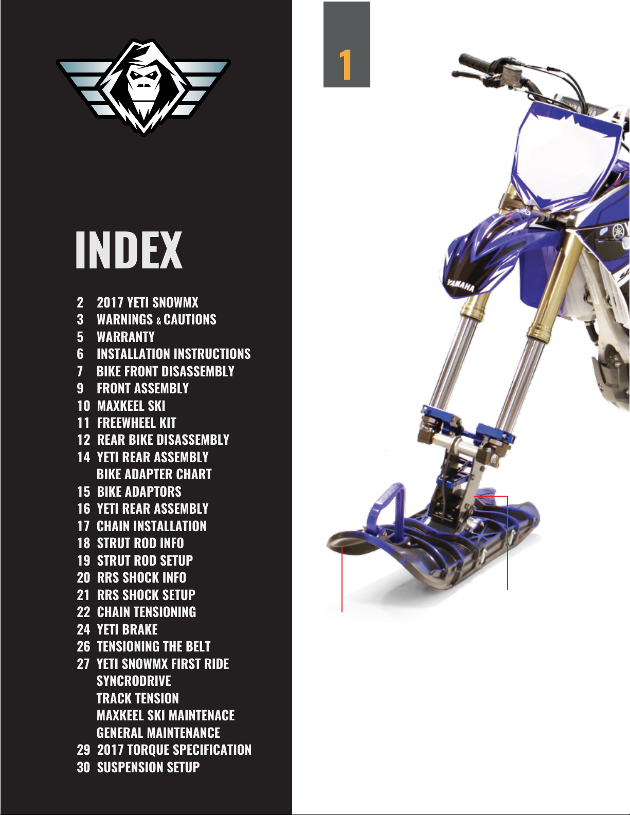
FRONT ASSEMBLY
MAXKEEL
Exoskeleton design with
extra deep center keel,
equipped with hardox
cutting blades and center
skagg, offering you the
ultimate control of your YETI
on all snow conditions.
SPINDLE
Equipped with (3) carbon
fiber blades, this spindle
has all it’s billet aluminum
parts fastened with titanium
bolts, producing a dependable strong mount to the
MAXKEEL ski.
Page 3
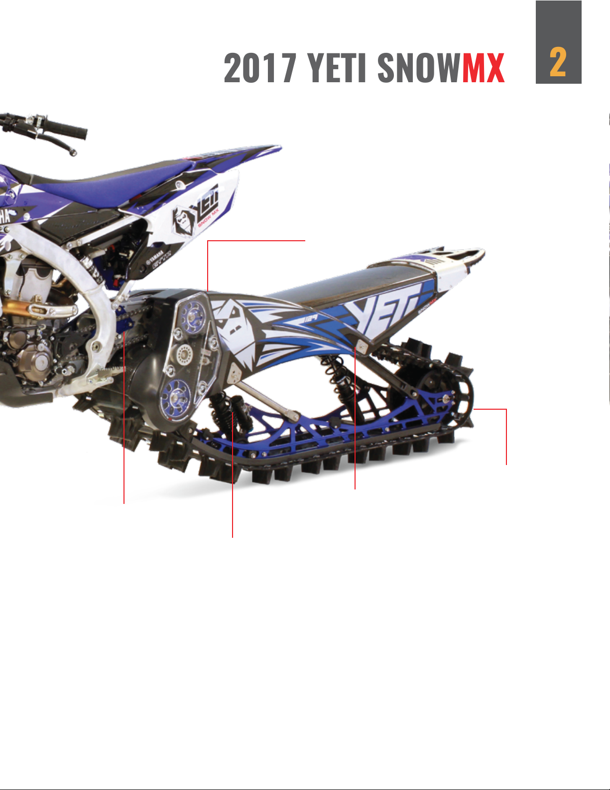
2017 YETI SNOWMX
SYNCRODRIVE
Designed by C3 Powersports, this
belt drive system maximizes the
efficiency of your motorcycles power
delivery, while allowing simple
gearing changes, in a virtually
maintenance free package.
2
BIKE MOUNT
Billet aluminum tunnel
plates, bike mount plates,
eccentric cam for chain
tensioning; it’s the heart of
the YETI’s mount system.
SUSPENSION
“Piggy back”
reservoir shock system, with
20 clicks compression
dampening adjuster for
ultimate control trail with
ease. Add The RRS shock
system to increases the
suspension travel up to
for higher performance
22”
CHASSIS
With 16 layers of carbon
fiber for the ultimate in
strength to weight ratio,
clear coat finish, underlaid
custom graphics, this
chassis is built to aerospace standards in an
autoclave chamber. The
resilience and lightweight
of this design will push your
ride to a new level. Backed
by our Carbon Chassis
REAR ASSEMBLY
MAXTRAK II
New for 2017, enhanced
design to break through the
crust and heavy wet snow.
This lightweight and single
ply track with 2.5” tall lugs
will accelerate you faster
then you ever dreamed and
higher than ever before.
Exchange program.
Page 4
3
WARNINGS CAUTIONS
WARNING! BE SURE YOU HAVE REVIEWED AND UNDERSTAND THE WARNINGS, INSTRUCTIONS, AND CONTENT OF THE OWNERS MANUAL FOR YOUR MOTORCYCLE AND
THE YETI SNOWMX BEFORE RIDING.
THESE INSTRUCTIONS CONTAIN MANY ! WARNINGS ! AND ! CAUTIONS ! CONCERNING
THE CONSEQUENCES OF OFF-ROAD SNOWMX RIDING. THE COMBINATION OF THE
SAFETY ALERT SYMBOL AND THE WORD ! WARNING ! INDICATES A POTENTIALLY
HAZARDOUS SITUATION, WHICH, IF NOT AVOIDED, COULD RESULT IN SERIOUS INJURY
OR EVEN DEATH. THE COMBINATION OF THE SAFETY ALERT SYMBOL AND THE WORD !
CAUTION ! INDICATES A POTENTIALLY HAZARDOUS SITUATION WHICH, IF NOT
AVOIDED, MAY RESULT IN A MINOR OR MODERATE INJURY, OR DAMAGE TO YOUR
YETI SNOWMX, OR A COMPONENT.
Because the consequences of not following a “Warning,” usually include “you may lose control and fall”
which could result in serious personal injury or even death, we may not repeat this in conjunction with each
warning. Due to the unlimited potential hazards of SNOWMX riding. It is impossible to anticipate every
situation or condition, which may occur. A practice or situation may be unsafe but not anticipated by this
manual. Ride safe, ride smart, and use common sense to avoid potential hazards.
WARNING! MOUNTAINS HAVE MANY HAZARDS AND TERRAIN TRAPS THAT MAY BE
UN-NAVIGABLE AND OR DANGEROUS, INCLUDING AVALANCHE CONDITIONS, BE
AWARE.
YETI SNOWMX is intended for snow and mountain use. All snow and mountain MX riding is potentially
hazardous and dangerous; knowledge and experience are critical to reduce the risk of serious injury or even
death. Be aware of the environment that you are riding in, as well as snow, avalanche, and weather
conditions. Be sure to carry proper gear and supplies for a safe ride in and out.
WARNING! EXTREME WEATHER MAY CAUSE WHITEOUT CONDITIONS, OR LOSS OF
DIRECTION. KNOW A WAY OUT AT ALL TIMES.
An off road MX bike equipped with the YETI SNOWMX can take you to places that you might not know
how to come down from, or far off the normal mountain/trail riding trail system, or you may end up in a
terrain trap. Riding beyond your abilities, may cause injury or even death. Respect all riding area’s, know
the boundaries and the hazards, and always have a back up plan in case of foul weather.
Proper riding equipment, such as an approved helmet, adequate clothing for all weather conditions, emergency radio’s and enough food to stay overnight in case of emergency is recommended. It is important to
have a proper avalanche beacon, probe, shovel and avalanche training; there are no excuses! Avalanches
can happen to anyone, and they happen fast. PREPERATION AND TRAINING ARE KEY. Snowmobile
search and rescue teams may not be able to reach you on a YETI SNOWMX equipped MX bike. Never ride
alone. Being prepared makes for a safe and enjoyable ride
CAUTION! YOUR MX BIKE WAS NOT DESIGNED TO OPERATE AS A SNOW MX BIKE.
ATTACHING A YETI SNOWMX TRACK SYSTEM MAY VOID OR AFFECT YOUR MANUFACTURES WARRANTY. CHECK WITH YOUR MX BIKE DEALER FOR FURTHER QUESTIONS.
YETI SNOWMX IS NOT RESPONSIBLE FOR ANY FAILURES OF YOUR MX BIKE’S PARTS.
THE RECOMMENDED MANUFACTURES MAINTENANCE SCHEDULE WILL NEED TO BE
ALTERED FOR SNOW MX RIDING, PLEASE ADJUST THE TIMING OF MAINTENANCE
ACCORDINGLY.
.
Page 5
WARNINGS & CAUTIONS
A YETI SNOWMX equipped MX bike is capable of many extreme maneuvers. The action(s) depicted in
advertisements, and promos ect, are being performed by professional riders with many years of riding
experience. Even though these riders have years of training and experience they often get seriously injured.
It is also foreseeable that during some extreme jumps, stunts or freeriding, the rider may exceed the design
capacity of the YETI SNOWMX system, which may result in serious injury or even death.
WARNING! OFF ROAD RIDING IS DANGEROUS, AND THE RIDER ASSUMES THE RISK OF
INJURY OR DEATH
44
All off road freeriding, jumping, boondocking and hill climbing is extremely dangerous, the rider voluntarily
assumes the risk that components may bend or break, and voluntarily assumes the risk of injury or death.
Respect the riding area, other riders, and pack out what you pack in! Enjoy your YETI SNOWMX kit. This is
the most fun we have ever had burning gas, and we have spent a lifetime, burning lots of it!
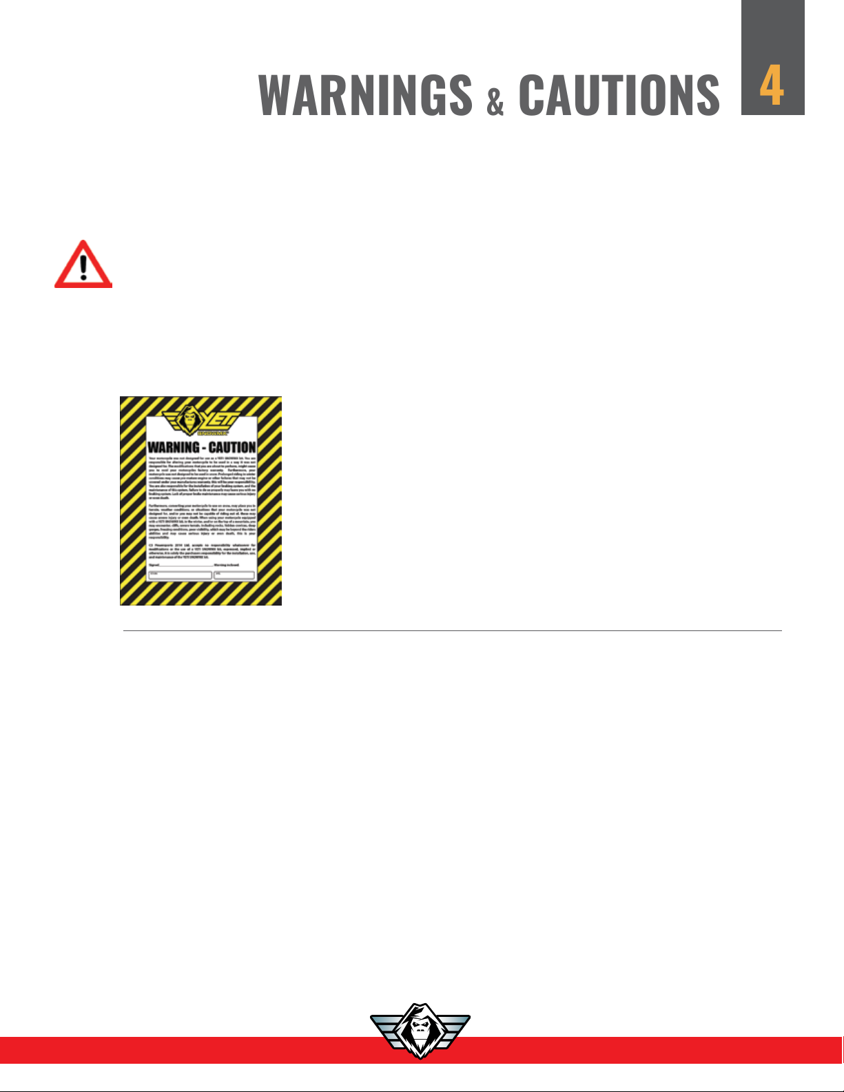
Each YETI SNOWMX is shipped with a Warning – Caution sheet,
this sheet is placed on top of the YETI rear assembly as our final notice
that there are many dangers or potentially hazardous situations that
may cause serious bodily injury or death to YETI SNOWMX riders.
We place this sheet on each YETI and sign off that we have warned
each customer of these potentially hazardous situations.
Each customer assumes all risk and liability of off-road riding their
motorcycle equipped with a YETI SNOWMX.
®
Page 6
5
WARRANTY
THIS IS YOUR RESPONSIBILITY!
C3 Powersports 2014 Ltd., warranties all products to be free of manufacturer defects for the period of (2)
years from the date of delivery to the original purchaser. This warranty is for parts coverage only, not including labor. This warranty is transferrable to to any subsequent owners IF the new owner(s) register with C3
Powersports on the YETI SNOWMX website or mail in their warranty card.
All warranty terms, both stated and implied are subject to C3 Powersports discretion and final approval.
Maintenance items are not covered under warranty and include items such as hyfax, skaggs, bearings,
bushings etc. C3 Powersports 2014 Ltd., reserves the right to refuse warranty coverage or service at any time.
Warranty process as follows,
1) C3 Powersports 2014 Ltd., requires notification PRIOR to replacement of any part under this warranty.
2) Replacement and or repaired parts will be supplied only upon receipt of defective parts.
3) Customer is responsible for shipping of the warrantable parts to and from C3 Powersports 2014 Ltd.,
Location.
4) C3 Powersports 2014 LTD., shall have no obligation under this warranty if:
- The owner fails to notify C3 Powersports of any possible defect in workmanship.
- The YETI SNOWMX is improperly installed
- The YETI SNOWMX is improperly maintained.
- The YETI SNOWMX is used in an application that it was not designed for.
- The customer continues to use the YETI SNOWMX after initial malfunction.
- The YETI SNOWMX is not registered with C3 Powersports 2014 Ltd.
C3 Powersports 2014 Ltd., is limited to replacement and/or repair of defective products for the period of 2
years from original date of purchase. C3 Powersports 2014 Ltd., has no other obligation or liability for injury,
death or damage resulting from any use of it’s products.
WARRANTY IS ONLY VALID FOR TWO YEAR FROM DATE OF PURCHASE.
WARRANTY IS TRANSFERRABLE TO THE NEXT OWNER IF SOLD WITHIN THE FIRST 12
MONTHS OF OWNERSHIP WHEN ACCOMPANIED WITH THE ORIGINAL RECEIPT.
YOUR WARRANTY IS NOT VALID UNLESS IT IS REGISTERED WITH YETI SNOWMX.
(Register with us by completing the warranty card, located in back of the manual and mailing it in, or by
completing the online form at www.yetisnowmx.ca.)
Page 7
FOR YETI SNOWMX 120 - 129 - 137
INSTALLATION INSTRUCTIONS
These installation instructions are designed to work in conjunction with the owner’s manual of your MX bike
supplied by your manufacturer. We will refer to your MX bike manufacturers instructions regarding fasteners,
torque specs and assembly or dis-assembly procedures.
Please read through the instructions first and familiarize yourself with the installation steps. There may be tips
and tricks that will aid the installation process. There will be different steps for each brand of MX bike. Please
refer to www.yetisnowmx.ca for steps that you do not see here. The most up to date info will be on our
website.
YETI SNOWMX offers special tools designed to service your YETI SNOWMX kit. These tools are for long term
maintenance needs, such as installation and removal of shafts, and drive plates. They are available through
your YETI SNOWMX dealer.
NOTE: There are many FAQ’s that are on the YETI SNOWMX website. We suggest if you have any questions
after reading both this instruction manual and our website, contact us either by clicking “ASK YETI or calling us
at the shop (780) 419 2040.
6
Always start with a clean bike and a clean working area with adequate lighting. Place your bike on your MX
stand, and secure it properly. You will require basic hand tools to complete your YETI SNOWMX installation metric wrenches, sockets, pliers, a hammer, and an alignment punch. You will also require 500ml of your
manufactures specified brake fluid to bleed your brakes.
We recommend completing the instructions in the order they are presented here. Our YETI SNOWMX installation video on our YouTube channel will demonstrate why this makes the installation of the YETI easier, and
safer. Watch the installation video during your install process, and follow along step by step.
If you are new to motorcycle mechanics and think you may forget how your bike goes back together, take
pictures of each part as you remove it, and the bolts holding it together, this will help you later upon re-assembly as a MX bike.
NOTE: SEE PAGE 29 FOR ALL YETI SNOWMX BOLT TORQUE SPECIFICATIONS AND LOCKTITE REQUIREMENTS.
NOTE: WE RECOMMEND USING ASSEMBLY GREASE ON THE BACK OF ALL FASTENER HEADS WHERE THEY COME INTO CONTACT
WITH ANODIZED ALUMINUM PARTS.
Page 8
BIKE FRONT DISASSEMBLY
7
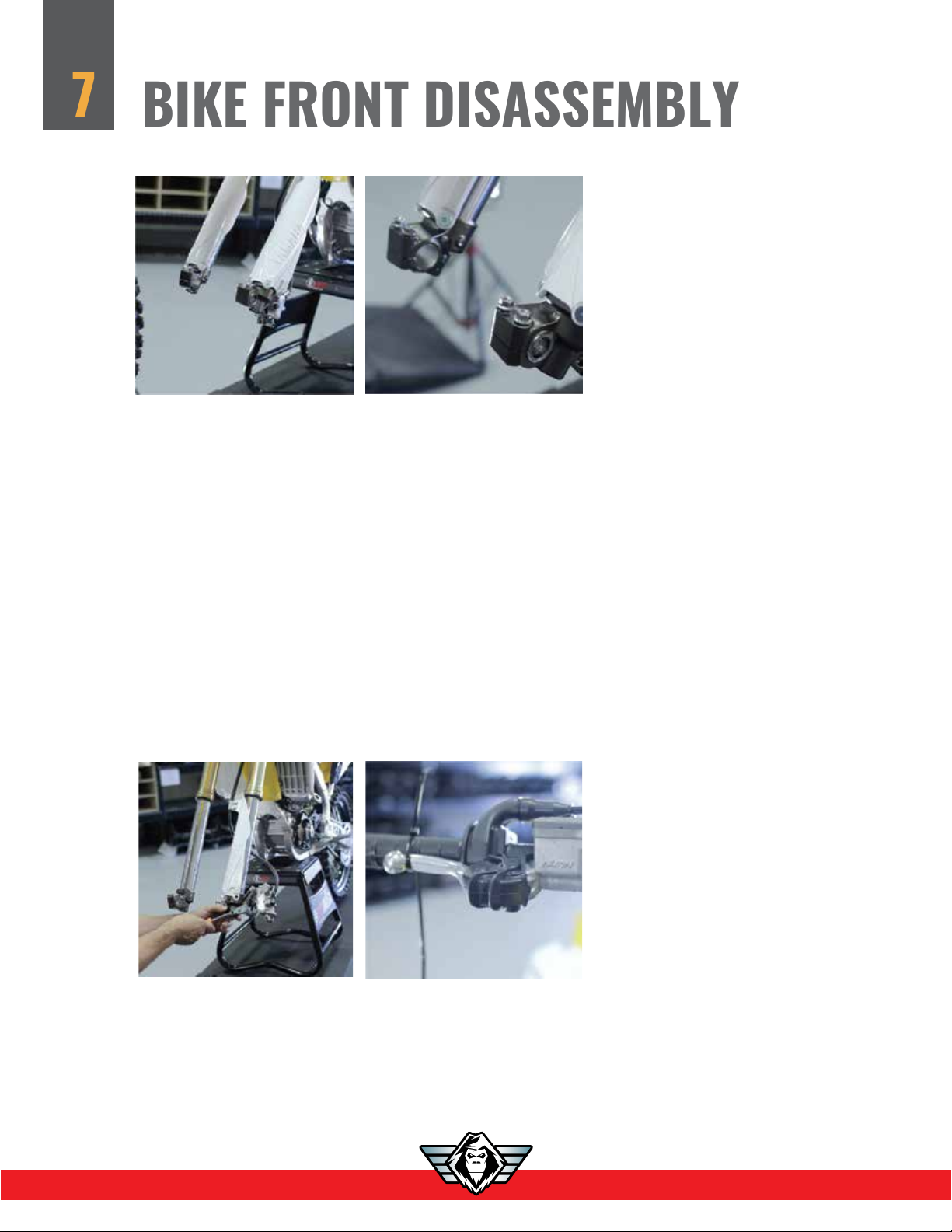
1. Remove front axle bolt and nut, leave in axle pinch bolts, as they will be used again.
FOR THIS INSTALLATION DEMONSTRATION WE ARE USING A 2016 YZ450F FOR PHOTO’S.
NOT ALL BIKES WILL HAVE THE SAME FASTNERS OR PARTS, PLEASE REFER TO OUR WEBSITE, YOUTUBE
CHANNEL, AND READ YOUR OWNERS MANUAL FOR ADDITIONAL SUPPORT.
2. Remove front fork guards.
NOTE: SOME BIKES WILL NOT BE ABLE TO REUSE THE FACTORY FORK GUARDS, AND/OR REQUIRE A
CUSTOM TRIMMING TO FIT, SO WE RECOMMEND LEAVING THEM OFF UNTIL SUMMER.
NOTE: WE DO NOT RECOMMEND THE USE OF NEOPRENE FORK SOCKS. THEY CAN FREEZE, AND
BUNCH UP AT THE BOTTOM OF YOUR FORKS ON THE YETI FORK CLAMPS. THEY WILL DAMAGE THE SEALS
AS YOU BOTTOM OUT YOUR FORKS. THERE IS A GROOVE MACHINED INTO THE FORK CLAMPS WHERE
THE SEAL FITS UPON BOTTOMING OUT.
3. Remove front brake caliper. Unhook the speedo sensor and/ or speedometer/odometer
if applicable or in your way.
NOTE: DO NOT UNHOOK THE BRAKE LINE OR RELEASE THE BRAKE FLUID.
4. Now that your brake caliper is removed, squeeze your front brake leaver until it touches
the handle bar, zip tie the front brake leaver to handle bar.
NOTE: YETI SNOWMX RECOMMENDS USING THE FRONT MASTER CYLINDER TO OPERATE THE YETI’S BRAKING
SYSTEM. A BRAKE LINE IS SUPPLIED TO ATTACH TO YOUR MX BIKES FRONT BRAKE MASTER CYLINDER TO THE YETI’S
BRAKE CALIPER.
Page 9
BIKE FRONT DISASSEMBLY
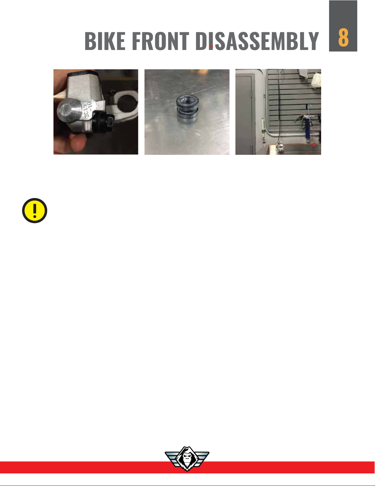
5. Remove the banjo bolt holding your brake line, and (2) crush washers. Install supplied rubber grommit
®
located in the YETI parts box on to the banjo bolt and tighten finger tight. This will stop any fluid loss while
you work on other parts of the bike.
CAUTION! MAINTAINING YOUR MX BIKE’S BRAKING SYSTEM IN SUMMER AND
WINTER IS CRITICAL TO YOUR SAFETY. CHECK YOUR MX BIKE’S BRAKING SYSTEMS
BEFORE HEADING OUT ON A RIDE.
8
6. Remove the assembled brake line with caliper on the end and hang on your wall out of the way
until re-install next spring. Be sure to do a full flush of brake fluid as this point in time.
7
Page 10
9
FRONT ASSEMBLY
SPINDLE & MAXKEEL SKI
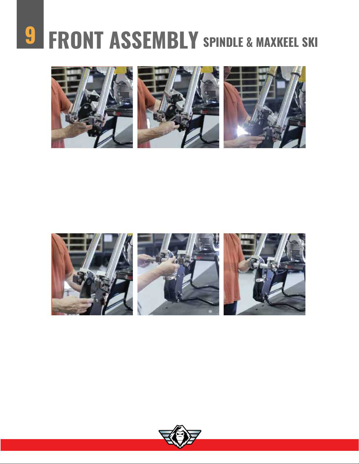
7. Install the complete front spindle. Spindle will slip in between the two lower fork tubes, twist and slide
down to get in place. You may need to try this a few times. Watch our Youtube video on spindle
installation for further instructions.
8. Re-install your front axle with the YETI axle spacers, they will be identified with LH and RH. If you are
not sure which axle spacer goes on either side, go to our website and use the YETIVERTER on the store
and it will assist you on identifying which side the spacers installation.
NOTE: DEPENDING ON BIKE MODEL AXLE SPACERS MAY BE THE SAME OR DIFFERENT
FROM LEFT TO RIGHT.
9. Make sure the YETI axle spacer locater collar is through the center carbon blade, the axle spacers
will be flush against the carbon fiber when installed correctly. The final assembled width will be equal
to the width of your MX front wheel. Finger tighten bolts when reassembling.
8
Page 11

MAXKEEL SKI
NOTE: BEVEL EDGE MATCHES
10. Install the two fork clamp caps (clamps have a top and bottom). Match up the inside bevel on the
clamp cap with the inside bevel on the fork clamp. Each clamp cap also has a notch to clear the brake
caliper mount. Install the (4) M8x1.25 socket cap bolts with your 6mm Allen key, and torque to 18 ft/lbs
with BLUE LOCTITE. Torque, your front axle, and axle pinch bolts to your MX bike manufactures
specifications.
10
WARNING! THE YETI CARBON FRONT SPINDLE IS ASSEMBLED WITH SEVERAL
M8 TITANIUM BOLTS USING BLUE LOCTITE. CHECK BOLTS AFTER FIRST RIDE,
THEN AFTER EVERY 12 DAYS OF RIDING. PROPER TORQUE IS 18-20FT LBS.
11. Install the MAXKEEL ski on the bottom of the YETI front spindle. Supplied is an M10 x110mm long
titanium bolt with a 17mm hex head, and a 17mm lock nut. Torque the front bolt to 50 ft/lbs use.
NOTE: THE SKI RUBBER IS A MAINTENANCE ITEM. WE SUGGEST YOU INSPECT THIS PART FOR WEAR AND CRUSH.
THIS PART IS DESIGNED TO KEEP YOUR SKI TIP UP, AND IT CAN WEAR AND CRUSH OVER TIME.
Page 12
FREEWHEEL KIT
11
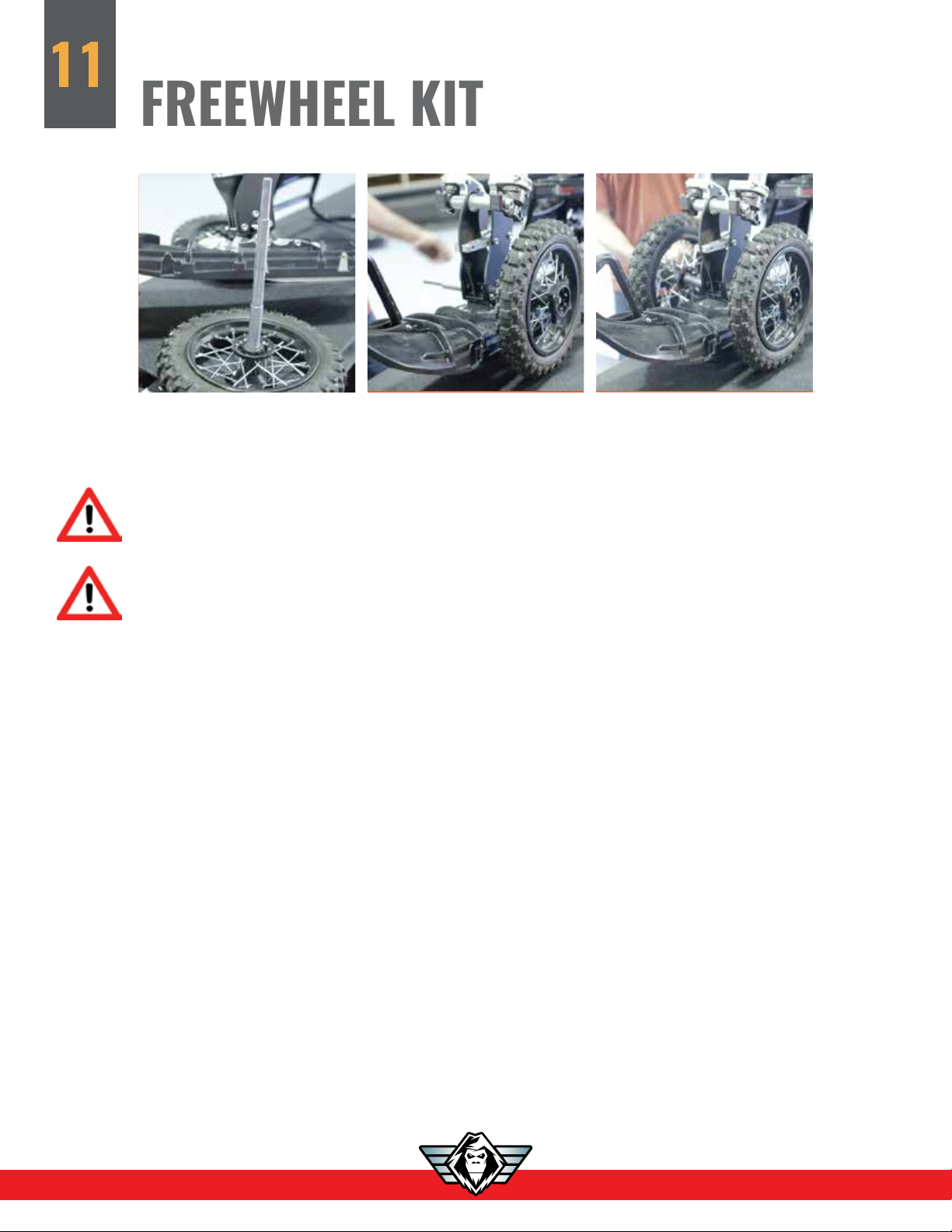
12. Install the FREEWHEEL KIT on your spindle. you can go to our YETI youtube channel to watch our
videos on how to install and use the FREEWHEEL KIT for more info.
WARNING! THE YETI FREEWHEEL KIT WAS DESIGNED TO HELP MOVE OR LOAD
YOUR YETI EQUIPPED MX BIKE AROUND YOUR GARAGE, YARD OR LOAD IN YOUR
TRAILER.
WARNING! YOUR MX BIKE’S HANDLING CHARACTERISTICS WITH THE
FREEWHEEL KIT WILL BE VERY DIFFERENT FROM YOUR MX BIKES INTENDED
HANDLING. RIDING YOUR MX BIKE WITH THE FREEWHEEL KIT ATTACHED CAN
CAUSE SERIOUS INJURY OR EVEN DEATH.
Page 13

13. Remove the rear brake master cylinder as one complete piece and leave it attached to the rear
REAR BIKE DISASSEMBLY
swingarm. DO NOT LOOSEN THE REAR BRAKE LINE. Refer to your owner’s manual for any details,
IF you remove the rear brake master cylinder this way you will not loose any fluid, re-installation in the
spring will be very quick, and will not require the bleeding of the rear brake assembly.
14. Remove the rear mud deflector, located behind the rear shock.
12
15. Remove the bike chain. Your YETI will be installed with a 62 link chain that
is provided.
16. Remove the chain rollers or sliders.
NOTE: YOUR BIKE MAY HAVE ROLLER(S), OR SLIDER(S). EACH YETI COMES WITH 2 CHAIN SLIDERS. NOT ALL MX BIKE FACTORY
CHAIN SLIDERS WILL WORK WITH THE YETI. THE YETI CHAIN SLIDERS ARE ENOUGH TO PROPERLY USE THE YETI, HOWEVER,
YOU MAY ADD MORE IF YOU FEEL IT IS REQUIRED FOR YOUR SPECIFIC BIKE. WE RECOMMEND LEAVING YOUR FACTORY
CHAIN SPROCKET PROTECTOR ON YOUR BIKE.
17. Remove the lower suspension linkage bolts that attach to your frame.
NOTE: SOME BIKES, SUCH AS THE KTM PDS SUSPENSION BIKES WILL HAVE NO LOWER LINKAGE.
18. Remove the upper rear shock bolt.
NOTE: THIS BOLT WILL BE RE-USED
Page 14

13
19. Remove the swing arm nut and bolt.
NOTE: THIS BOLT WILL BE RE-USED
20. Remove the swingarm assembly.
NOTE: PLEASE BE SURE YOUR BIKE IS COMPLETELY SECURE, SO WHEN YOU REMOVE THIS ASSEMBLY YOUR BIKE DOES
NOT TIP OFF YOUR STAND. REFER TO STEP 12 ON FREEWHEEL KIT INSTALLATION IF NEEDED. YOU WILL NOT NEED TO
RE-USE ANY PARTS HERE, STORE THEM AWAY UNTIL NEXT SEASON.
NOTE: IF YOU ARE RIDING A YAMAHA YZ FX/WR, THERE WILL BE AN ADDITIONAL FOOT PEG MOUNT SHIPPED WITH YOUR
YETI SNOW MX KIT. YOU WILL NEED TO REMOVE THE LH FOOTPEG AND REMOVE THE KICK STAND MOUNT, AND REPLACE
IT WITH THE NEW MOUNT PROVIDED FROM THE YZ450F. THIS WILL NOW PROVIDE ADEQUATE ROOM FOR THE YETI KIT
TO BE INSTALLED.
Page 15

YETI REAR ASSEMBLY
14
YETI 2017 ADAPTER CHART
8.5"
11 3/4
12.000
11.00
11.250
HONDA
2017
CUR
CRF 450 R/RX
8.5"
12.250
HUSQVARNA
10.875
11.125
HUSQVARNA
10.875
11.125
HUSQVARNA
10.875
11.125
HUSQVARNA
10.875
11.125
7.5"
7.5"
7.5"
11.1875
11.313
12.000
12.250
12.000
12.250
12.000
12.250
10.875
11.125
10.875
11.125
10.875
11.125
10.875
11.125
10.875
11.125
10.875
11.125
10.875
11.125
10.875
11.125
10.875
11.125
11.1875
11.313
11.00
11.500
6.5"
6.5"
9.75
10.000
9.75
10.000
9.75
10.000
9.75
10.000
9.75
10.000
9.75
10.000
9.75
10.000
8"
7"
10.000
IGUS BEARING RH BIKE MOUNT ADAPTER
BUSHING
Brand
BETA 2015 CUR 350-480
HONDA 2005 2012 CRF 450
HONDA 2013 2016 CRF 450
HUSABERG 2009 2014 390-570 FE
KAWASAKI 2005 2012 KX250F
KAWASAKI 2013 CUR KX250F
KAWASAKI 2006 2014 KX450F
KAWASAKI 2015 CUR KX450F
KTM 2007 2010
KTM 2003 CUR 400-530 EXC/MXC/XCW
KTM 2008 CUR 250-300 PDS
KTM 2011 2013 450 SXF/XCF
KTM 2011 2014 350 XCW/EXC/SXF/XCF
KTM 2012 2012 DUNGEY
KTM 2013 2014 450 SXF/XCF
KTM 2012 CUR 250-300 SX/XC Linkage
KTM 2015 2015 350 SXF/XCF
KTM 2014 2014 DUNGEY
KTM 2015 2015 SXF/XCF 450
KTM 2016 CUR 250-450 SXF/XCF
SUZUKI 2015 CUR RMZ450
SHERCO 2015 CUR 300 - 450 YPBM2101 YPBM2102 YPBM2089 YPBM2089
TM 2014 2014 450 YABM2231 YABM2232 YABM2234 YABM2234
TM 2016 CUR 450 YABM2231 YABM2232 YABM2234 YABM2234
YAMAHA 2006 2007 YZ450F
YAMAHA 2005 2011 WR450
YAMAHA 2008 2009 YZ450F
YAMAHA 2010 2013 YZ450F
YAMAHA
YAMAHA
YAMAHA
YAMAHA 2014 CUR YZ250
YAMAHA 2012 2015 WR450
Year
Start
2014 2014 250-450
2014 2015 501 FE/FC/TE/TC
2015 CUR 250-450
2016 CUR 501 FE/FC/TE/TC
2014 CUR
2014 CUR
2016 CUR
Year
End Model
450-505 SXF/XCF YPBM2090 YPBM2090 YPBM2078 YPBM2078
YZFX 450, WR 450
LH BIKE MOUNT ADAPTER
BIKE MOUNT
ADAPTER LH
YPBM1744 YPBM1744 YPBM1745 YPBM1745
YPBM2099 YPBM2100 YPBM2087 YPBM2088
YPBM2095 YPBM2096 YPBM2083 YPBM2084
YPBM1744 YPBM1744 YPBM1745 YPBM1745
YPBM1744 YPBM1744 YPBM1745 YPBM1745
YPBM1744 YPBM1744 YPBM1745 YPBM1745
YPBM1744 YPBM1744 YPBM1745 YPBM1745
YPBM1744 YPBM1744 YPBM1745 YPBM1745
YPBM2094 YPBM2094 YPBM2082 YPBM2082
YPBM2094 YPBM2094 YPBM2082 YPBM2082
YPBM2094 YPBM2094 YPBM2082 YPBM2082
YPBM2094 YPBM2094 YPBM2082 YPBM2082
YPBM1744 YPBM1744 YPBM1745 YPBM1745
YPBM1744 YPBM1744 YPBM1745 YPBM1745
YPBM1744 YPBM1744 YPBM1745 YPBM1745
YPBM2090 YPBM2090 YPBM2078 YPBM2078
YPBM1744 YPBM1744 YPBM1745 YPBM1745
YPBM1744 YPBM1744 YPBM1745 YPBM1745
YPBM1744 YPBM1744 YPBM1745 YPBM1745
YPBM2090 YPBM2090 YPBM2078 YPBM2078
YPBM1744 YPBM1744 YPBM1745 YPBM1745
YPBM1744 YPBM1744 YPBM1745 YPBM1745
YPBM1744 YPBM1744 YPBM1745 YPBM1745
YPBM2093 YPBM2093 YPBM2081 YPBM2081
YPBM2091 YPBM2092 YPBM2079 YPBM2086
YPBM2091 YPBM2092 YPBM2079 YPBM2086
YPBM2091 YPBM2092 YPBM2079 YPBM2086
YPBM1758 YPBM1759 YPBM1757 YPBM1757
YZF 250-450
YZFX 250
YPBM1758 YPBM1759 YPBM1757 YPBM1757
YPBM1758 YPBM1759 YPBM1757 YPBM1757
YPBM1758 YPBM1759 YPBM1757 YPBM1757
YPBM1758 YPBM1759 YPBM2086 YPBM2086
YPBM2091 YPBM2092 YPBM2079 YPBM2086
BUSHING CHAIN TENSIONNER
BIKE MOUNT
ADAPTER RH
BIKE MOUNT
ADAPTER
BUSHING LH
BIKE MOUNT
ADAPTER
BUSHING RH
NOTE: IF YOUR BIKE IS NOT LISTED, SEE PAGE 18-21 FOR MORE INFO
SPRING
RIGID STRUT
RECOMMENDED
STARTING
STRUT ROD
LENGTH EYE TO
EYE IN INCHES
RRS MINIMUM
SHOCK
LENGTH EYE
TO EYE IN
INCHES
Page 16

BIKE ADAPTORS
15
EACH BIKE HAS A DIFFERENT AIR BOX, SOME MAY REQUIRE MINOR TRIMMING OF PLASTIC, OR SUBFRAME MODIFICATION
TO PROVIDE CLEARANCE FOR THE YETI TO FIT. SEE BIKE ADAPTER CHART, OUR WEBSITE OR OUR YOUTUBE CHANNEL
FOR FURTHER DETAILS.
.
21. Locate the (2) YETI bike adaptors, and (2) bike adaptor bushings in the YETI bike adaptor box.
Take note of which bike adaptor is the LH and RH, and which bushing is LH and RH also. If your bike
adaptors and bushings are not identified as to which are RH and LH, please to the previous page (14)
for the correct listings of each part for your particular bike. Some bikes use the same bike adaptors and
bushings for the LH and RH, some do not, and each part has a part number on it for easy identification.
Use the bike adaptor tool provided with your kit to install the bike adaptors, and a slight lubricant will
help slide them in place.
TIP: TO HELP GUIDE THE ADAPTER IN, USE THE LONGER 25MM SUPPLIED BOLT ON THE OUTSIDE OF THE
MOUNT PLATE FOR NOW. BE SURE TO REMOVE IT AND INSTALL IT ON THE INSIDE OF THE BIKE MOUNT
PLATE WHEN DONE INSERTING THE ADAPTER. SECURE YOUR ADAPTER WITH THE 20MM BOLT ON THE
OUTSIDE. BE SURE TO DO THIS STEP OTHERWISE IT WILL CAUSE THE BIKE MOUNT TO JAMB.
NOTE: BIKE ADAPTERS MAY BE DIFFERENT WIDTHS, TAKE NOTE. READ ADAPTER CHART LOCATED PAGE 14.
22. To prepare your YETI SNOWMX kit for installation, install the auto chain tensioner and spring on
the LH bike mount adaptor. Second, place the rear assembly of the YETI behind your MX bike, where
your swingarm used to be.
20mm when finished
Ensure all bike mount plate bolt
are loosen then extend the bike
mount plates to full extension using
the eccentric bolt.
Page 17

NOTES: THE YETI SHOULD SLIDE IN PLACE AS THE PARTS ARE MACHINED FOR EACH BIKE. WE HAVE NOTED SOME TOLERANCE
DIFFERENCES ON MX BIKES BETWEEN THE FRAME AND THE ENGINE. THE BIKE MOUNT ADAPTORS WILL MEASURE THE SAME
AS YOUR SWING ARM BUSHINGS. A BIT OF WIGGLING OR EVEN A SLIGHT PRY TO OPEN UP THE GAP TO INSTALL THE
YETI IS NORMAL. HAVING THE BIKE MOUNT PLATE EXTENDED FULLY IS IMPORTANT SO THE YETI IS NOT HITTING ANYTHING.
IF SOMETHING SEEMS WAY OUT, CHECK THE BIKE ADAPTER CHART TO CONFIRM YOUR PART NUMBERS ON THE BIKE
ADAPTORS ARE CORRECT AND INSTALLED IN THE CORRECT PLACEMENT OF LEFT AND RIGHT. SOME BIKE MOUNT ADAPTERS
ARE THE SAME LEFT AND RIGHT, SOME ARE DIFFERENT.
23. before installing your strut rod or RRS shock kit, check your specification page 14 for an eye to eye
length measurement.
24. Check that the bushings are in the strut rod ends and/or the RRS shock. (1/2’’ rod end is left hand
YETI REAR ASSEMBLY
thread) Before installing the strutrod, be sure that the 5/8” jamb nut is installed on the rod end. Install
the rod end with the bushings into the top mount where the shock on your motorcycle used to go, install
the top shock bolt and torque to the manufacturers specifications.
16
NOTE: USE LOCTITE AS PER YOUR MX BIKE’S SPECIFICATIONS.
25. Slide the YETI assembly into position, and once it is installed where your swingarm used to be,
have an assistant raise the rear of the YETI kit so that the bike mount bolt may be installed
in the bottom rod end. Ensure bushings are installed and reinstall the rear swingarm bolt, and torque to
your manufactures specifications.
Page 18

CHAIN INSTALLATION
17
26. Position the YETI so the track will rotate easily off the ground. (Either block your bike up on
a stand, or have someone lift up the rear of the YETI) Feed the chain in the front of the YETI, then into the
top chain hole, and over the top of the YETI chain drive sprocket. Rotate the track slowly forward and then
use a magnet to pull the chain out the bottom chain hole.
NOTE: TAKE NOTE OF HOW THE STRUT ROD IS ADJUSTED, IF IT IS ADJUSTED TOO LONG WHEN YOU ARE SETTING UP
THE YETI, THE CHAIN WILL NEVER BE LONG ENOUGH TO CONNECT. SOMETIMES SHORTENING THE STRUT ROD, AND
OR LIFTING THE REAR OF THE YETI WILL HELP YOU CONNECT THE CHAIN.
NOTE: SOME BIKES WILL REQUIRE A TRIMMING OF THE FACTORY AIR BOX TO ALLOW THE TOP OF THE YETI CLEAR THE
MX BIKE AIR BOX. YOU WILL NEED TO TRIM ACCORDINGLY. THE YETI KIT DOES NOT MOVE ONCE INSTALLED, AND 1/8’’ 1/4’’CLEARANCE IS ENOUGH SPACE BETWEEN THE YETI AND YOUR MX BIKE COMPONENTS.
27. After you have installed the chain, be sure to install the master link correctly using the supplied
grease and o rings in the correct direction. The open end of the chain master link clip should be facing
backwards of normal rotation.
NOTE: DO NOT TIGHTEN THE CHAIN YET AS THE STRUT ROD LENGTH EFFECTS THE CHAIN TENSION.
MASTER LINK INSTALLED
CORRECTLY
Page 19

STRUT ROD INFO
18
Without eye to eye measurements
NOTE: SEE OUR YOUTUBE VIDEO FOR STRUT ROD INSTALLATION TECHNICAL TIPS. WWW.YETISNOWMX.CA
See our YOUTUBE channel for Strut rod technical tips as each YETI SNOWMX can be fine tuned to rider
preference. The instructions below will provide a good starting point for Strut rod set up, and other adjustments
to fit your riding style.
Setting up the strut rod is the most important step to proper YETI SNOWMX handling. Adjusting the strut rod
will drastically effect how your MAXKEEL SKI handles in different snow conditions.
Each full rotation of the strut rod is equal to .100” of rear suspension rail lift or drop measured at the rear
shock shaft. These instructions will walk you through how to set up your strut rod, or watch the video on
Youtube on the YETI SNOWMX channel.
Each full rotation of the strut rod clockwise will lengthen the rod and raise the rear suspension rails
measured at the rear lower shock shaft .100”
Each full rotation of the strut rod counter clockwise will shorten the rod and raise the front of the suspension rails measured at the front lower shock shaft .100”
NOTE: THE LOWER ROD END IS LH THREAD.
The best initial YETI set up, is starting with the rear lower shock shaft .250”- .400” (1/4’’ - 3/8 ‘’) higher than
the front lower shock shaft. This is good for all conditions and rider styles. The front ski will “dart” or “grab”
when there is too much ski pressure, or when there is too little ski pressure, the effect will feel almost the same.
Most of the time we have found that a quick adjustment on the trail of two turns in either direction makes a
huge difference.
The pre-load on the front Raptor coil shock will also effect the amount of ski pressure. More preload on the
spring will lighten the ski pressure, and less pre-load will put more ski pressure on the ski.
NOTE: CHECK SHOCK SPRING PRE-LOAD SPECIFICATIONS DIAGRAM PAGE 30
Page 20

19
STRUT ROD SETUP
The new spec is to measure the height from the floor to the centre of the two lower shock cross shafts. The
rear shock cross shaft should measure .200”- .400” higher than the front shock cross shaft when the bike is
on flat ground while sitting on the centre skag (with no wheel kit installed).
STRUT ROD SETUP
NOTE: CHECK SPECIFICATION DIAGRAM PAGE 30
YOU MAY NEED A DIGITAL VERNIER CALIPER TO AID YOU SETUP THE STRUT ROD
Place your bike on the level ground, on the center ski skagg and on the track with the strut rod installed.
Measure the rear suspension rail tip. Take your measurement from the top of the slider to the floor at the
front lower shock cross shaft. Then measure the same at the rear shock cross shaft. Take the difference of the
two measurements and that is your rail tip.
Example: Front measurement is 2.075” from the top of the slider to the floor at the front lower shock cross
shaft. The rear measurement is 2.375” from the top of the slider to the floor at the rear lower shock cross
shaft. You take the difference of 2.075 ( front measurement) vs the 2.375” ( rear measurement) and you get
.300” of rail tip at at the rear.
IMPORTANT: AFTER YOU HAVE COMPLETED ADJUSTMENTS TO THE STRUT ROD, MAKE
SURE YOU TIGHTEN AND LOCK DOWN THE (2) HALF NUTS ON THE ROD ENDS AGAINST
THE STRUT ROD. FAILURE TO DO SO WILL CAUSE THE STRUT ROD, UNDER YOUR
BIKES VIBRATION TO SHORTEN ON IT’S OWN. THIS WILL EFFECT YOUR BIKES
HANDLING AND YOUR CHAIN TENSION WILL LOOSEN.
Now that the strut rod is set, and locked the chain can be tightened.
NOTE: SEE PAGE 22 FOR THIS STEP
Page 21

RRS SHOCK INFO
NOTE: SETTING UP THE RRS SHOCK IS AN IMPORTANT STEP TO PROPER YETI SNOWMX HANDLING. ADJUSTING THE RRS
SHOCK LENGHT WILL DRASTICALLY EFFECT HOW YOUR MAXKEEL SKI HANDLES IN DIFFERENT SNOW CONDITIONS. YOU
NEED TO KNOW HOW TO ADJUST THE RRS SHOCK TO SUIT YOUR RIDING STYLE.
Each complete rotation of the rod end on the RRS shock is equal to .050” of rear suspension rail lift or
drop measured at the rear shock shaft. Each ½ rotation of the rod end will adjust rail tip .050”.
NOTE: THE LOWER ROD END IS LH THREAD
These instructions will walk you through how to set up your RRS shock, for more indepth information
watch the videos on the YETI Youtube channel.
Each full rotation of the rod end counter clockwise will shorten the RRS shock and raise the rear
suspension rails measured at the rear lower shock shaft .050”
Each full rotation of the rod end clockwise will lengthen the RRS shock and l raise the front of the
suspension rails measured at the front lower shock shaft .050”
We have found the best initial YETI set up for the RRS, is to first set the track perfectly level to the ground.
Then, adjust the rod end 5 turns (1/4in) longer. This should give you the best setup for your RRS. This is
good for all conditions and rider styles.
20
NOTE: This is the opposite of the set up on the solid strut rod. The rear suspension front rail needs to be
tipped up on the RRS equipped bikes as they sag in when you sit on the bike.
The front rail tip up, compensates for the sag in the RRS shock, and the goal in the end is to have the
same .200”-.400” rear rail tip up when the rider sits on the bike. This is achieved by starting with the
front of the rails tipped up, prior to rider weight.
The front ski will “dart” or “grab” when there is too much ski pressure, or when there is too little ski
pressure, the effect will feel almost the same.
The pre-load on the front Raptor coil shock will also effect the amount of ski pressure. More preload on
the spring will lighten the ski pressure, and less pre-load will put more ski pressure on the ski.
NOTE: CHECK SHOCK SPRING PRE-LOAD SPECIFICATIONS DIAGRAM PAGE 30
Page 22

RRS SHOCK SETUP
21
Place your bike on the level ground, on the center ski skagg and on the track with the RRS shock installed. Have someone hold the bike up from the rear muffler or fender so the RRS shock is not sagged in.
Measure the rear rail tip. Take your measurement from the top of the slider to the floor at the front lower
shock cross shaft. Then measure the same at the rear shock cross shaft.
Take the difference of the two measurements and that is your rail tip.
NOTE: MAKE SURE TO START THE MEASUREMENTS WITH THE REAR RAIL TIP HIGH
Example: Front measurement is 2.075” from the top of the slider to the floor at the front lower shock
cross shaft. The rear measurement is 2.075” from the top of the slider to the floor at the rear lower shock
cross shaft. You take the difference of 2.075 ( front measurement) less the rear 2.075” ( rear measurement) and you get
2.075” – 2.075” = 0” of front rail tip up.
To complete the RRS setup now lengthen the rod end 5 turns (1/4in)
NOTE: THE REAR SUSPENSION WILL CREATE MORE REAR RAIL TIP UP AS IT GOES THROUGH THE COMPLETE RRS SHOCK
TRAVEL.
NOTE: EACH RRS SHOCK IS BIKE SPECIFIC AND WE HAVE BUILT IN A SAFETY FACTOR SO THAT IF YOU SCREW THE ROD
END IN TOO FAR IT WILL NOT CAUSE THE YETI CHASSIS TO HIT YOUR MOTORCYCLE SUBFRAME, AND IT WILL CLEAR YOUR
YETI UTILITY CAN.
If you are not sure what RRS shock that you have and what it fits you can go to the YETI SNOWMX
website and look up the specific information on each shock.
Page 23

CHAIN TENSIONING
Watch our YOUTUBE channel for all the information and video’s on how to tension the chain, and how
to swap Syncrodrive gears.
29. For this step you will need a 12mm socket on a 3/8 drive ratchet, 3” 3/8 drive extension
and the billet socket supplied.
22
A) Place your bike on the floor.
B) push the chain slider up and in towards the bike mount plate, hooking the end of the chain slider
in the plate, locking it out of the way. This will stop the chain slider from pushing against the chain
while you tension it.
C) Now loosen off the (3) 12mm bolts on each side of the bike mount plate.
NOTE: LOOSENING THE LOWER FRONT TWO 12MM BOLTS TOO MUCH WILL CAUSE THE “T” NUT ON THE BACK TO
FALL OFF, AND YOU MAY LOOSE THEM.
NOTE: IF YOU BIKE IS ON A MX STAND AND NOT ON THE FLOOR, TENSIONING THE CHAIN WILL BE VERY DIFFICULT,
IT IS RECOMMENDED THAT YOU TENSION THE CHAIN WITH YOUR BIKE ON THE FLOOR.
D) Now you can turn the YETI eccentric cam bolt clockwise to tension the chain or
counterclockwise to loosen the chain. Use your 12mm socket.
E) The chain should be tensioned to be snug, remove all chain slack.
F) Once you have set the chain tension, tighten up the bolts in this order
- The 23mm nut first, it can be tightened to 45-50ft/lbs it does most of the work.
- Then the strut block bolts to 25 ft/lbs (note: the 2017 YETI has M10 strut block bolts in all 4 locations)
- Finally tighten the two lower front bolts to 18ft/lbs
G) Now that the bolts are tight and complete, pull the chain slider out of the bike mount plate and the
spring will put tension on your chain.
Page 24

23
NOTE: THE ECCENTRIC BOLT WILL BARELY MOVE WHILE TAKING UP THE CHAIN SLACK ON DAILY RIDING ADJUSTMENTS.
IT WILL TAKE A BIT TO GET USED TO THIS. MANY TIMES WE FEEL THE BOLT HAS NOT EVEN TURNED, OR IT IS JAMMED,
BUT THAT IS BECAUSE THE CHAIN IS ALREADY AS TIGHT AS IT WILL GO.
NOTE: WHEN TENSIONING THE CHAIN ON THE HILL IT HELPS TO HAVE ANOTHER PERSON GRAB THE REAR BUMPER AND
GIVE THE YETI A SLIGHT WIGGLE UP AND DOWN WHILE KEEPING CLOCKWISE PRESSURE ON THE ECCENTRIC BOLT,
THIS WILL UNLOAD THE PRESSURE ON THE YETI, AND HELP IT SLIDE.
NOTE: IN RARE OCCASIONS SOME OF THE BIKES FRAMES ARE A TINY BIT WIDER THAN SPEC. IF YOUR YETI ECCENTRIC
CAM WILL NOT MOVE, THERE ARE TWO BACK UP STEPS, THAT WILL HELP:
1) HAVE A FRIEND PUT ANOTHER 12MM SOCKET ON THE OTHER END OF THE ECCENTRIC BOLT AND TURN THEM
SIMULTANEOUSLY IN THE SAME DIRECTION
2) SOMETIMES LOOSENING THE SWINGARM NUT WILL RELIEVE SOME TENSION ON THE YETI BILLET BIKE MOUNT PLATES
AND HELP THE ECCENTRIC BOLT TO TURN. YOU WILL FIND THAT THE SUPPLIED YETI BILLET SOCKET WILL ALSO FIT SOME
BIKES SWINGARM NUTS.
Page 25

YETI SNOWMX comes equipped with a SPEED BLEEDER brand checkvalve, in the brake
YETI BRAKE
BRAKE BLEEDING & BRAKE LINE
caliper. The YETI brake system gives you a consistent feel and is very responsive. Take your
time to bleed the brakes properly, and remove all the air from the system. Follow these steps
to ensure your brakes are bled properly.
WARNING ! YOUR BRAKES ARE IMPORTANT SAFETY EQUIPMENT ON YOUR MX
BIKE, THAT NEED TO BE MAINTAINED. IT IS THE OPERATORS RESPONSIBILITY
TO MAINTAIN BRAKING SYSTEM. FAILURE TO PERFORM PROPER MAINTENANCE
OR PRE RIDE CHECKS ON YOUR BRAKING SYSTEM MAY RESULT IN LOSS OF
CONTROL, CAUSING SERIOUS INJURY OR EVEN DEATH.
Route your brake line from the YETI SNOWMX up along the strut rod, along the frame to the
master cylinder. Stay away from any hot parts, sharp edges, and maintain large radius bends
in the brake line. The brake line is extra long, but take your time to plan your route. Secure
line with zip ties.
1. After routing your brake line, up to the front master cylinder, locate the medical syringe and clear
vinyl line that is supplied in your YETI parts box.
24
2. Attach the silicon line to the end of the syringe.
3. Open the SPEED BLEEDER checkvalve on the brake caliper 1/2 turn, then push the silicon line
onto the SPEED BLEEDER.
WARNING ! USE A NEW BOTTLE OF THE CORRECT BRAKE FLUID AS PER YOUR
MANUFACTURES SPECIFICATIONS. DO NOT MIX BRAKE FLUID TYPES! SOME
ARE NOT COMPATIBLE. LOSS OR INADEQUATE BRAKING MAY OCCUR CAUSING
SERIOUS INJURY OR DEATH. THESE ARE THE BRAKES THAT STOP YOUR BIKE,
PAY ATTENTION, AND DO THE BRAKE BLEEDING PROPERLY, AND MAINTAIN
YOUR BRAKING SYSTEM!
4. With your bottle of brake fluid secured, at the handle bar end (or with a helper) place the end
of the YETI brake line in the fluid (keep the line in an uphill angle), and once the brake line is
submerged in the fluid, pull on the syringe and prime the brake line with fluid.
5. Once brake fluid is filling the syringe, give it a pull to fill the syringe completely. Then close the
SPEED BLEEDER checkvalve.
6. Disconnect the silicon line, and squeeze the brand new clean fluid back into your brake fluid bottle.
Be sure to keep your primed brake line in the upward position.
7. Remove rubber grommit from master cylinder. Place the banjo bolt through the supplied copper crush
washer, through the banjo end on the brake line and then through the 2nd copper crush washer. Now
install on the front master cylinder. Tighten the banjo bolt, to your manufacturer’s specs. If you do not know
the specs it is very tight, and it will need to crush the crush washers, approximately 20 ft/lbs. See diagram
next page.
8. Cut the zip tie holding your front brake lever to the handle bar, remove the master cylinder
cover, and top off the brake fluid reservoir full.
9. SLOWLY wiggle the front brake lever, tiny 1/4 - 1/2 increments at first. Pull gently, watch for any air
bubbles coming out.
Page 26

25
10. Reconnect the silicon line to the SPEED BLEEDER , open it 1/2 turn again.
11. Now, fully pumping the master cylinder, the syringe will fill with fluid and watch for the air
bubbles leaving your brake system, filling the syringe. Be sure to not lose your prime on the master
cylinder and keep it topped off and full at all times.
12. You will need to close the SPEED BLEEDER when you are satisfied you do not see any air bubbles
leaving the brake caliper. Close it snugly and replace the rubber dust cap on the SPEED BLEEDER .
13. Fill the master cylinder until it is full to the rim, then place the master cylinder cap and tightnen it
down. The fluid will spill out over the edge. IT IS IMPORTANT TO OVER FILL THE MASTER CYLINDER.
This will stop air from entering the system again, if you tip your bike upside down in the snow.
Page 27

Each YETI SNOWMX model is equipped with a Syncrodrive belt system designed by C3 Powersports.
TENSIONING THE BELT
The recommended belt tension has been achieved through a collaboration of engineers, testing and
through many years of belt drive experience. It is a very easy to use system. A properly tensioned belt
will give you many maintenance free seasons of riding on the same belt.
26
A belt that is too loose, will snap, as a wave is created in the belt, and/or a shock load can occur.
The belt will skip teeth causing immediate belt failure. This same shock load can also happen if your
track is too loose and starts to ratchet on the drivers.
If you feel or hear your track ratcheting, or your belt skipping, you need to stop immediately and tension
your belt. Failure to do so will snap your Syncrodrive belt.
Tune into the YETI SNOWMX YOUTUBE channel and watch the maintenance videos or FAQ’s on belt
drive tension and track tension.
NOTE: BELTS SHOULD NOT BE NOT BE STORED IN A CIRCUMFERENCE LESS THAN A 2” RADIUS OR BELT DAMAGE WILL OCCUR.
The recommended YETI Syncrodrive belt tension is 400N for a brand new belt at a room temperature
22C or 72F. This is easily achieved by using the YETI belt tensioner gauge that is built into each YETI
Syncrodrive tensioner arm.
1. Slide the red tensioner gauge over to align with the outside edge of the drive belt.
2. Check the tension of your belt by squeezing with your two thumbs towards the tensioner wheel.
The correct belt tension is 7/16” of belt deflection, which is the width of the RED tension gauge.
NOTE: ONLY LOOSEN THE IDLER WHEEL NUT 1/2 A TURN DO NOT LOOSEN IT OFF ALL THE WAY. AFTER YOU HAVE
COMPLETED YOUR BELT TENSIONING, THEN TIGHTEN UP THE TENSIONER NUT. THE BELT TENSION WILL ALWAYS
INCREASE A SMALL AMOUNT. IF THE NUT IS LOOSENED OFF TOO MUCH WHEN YOU TIGHTEN IT BACK DOWN IT
WILL OVER TIGHTEN THE BELT (THE PULLEY WILL ROCK OVER WHEN OVER LOOSENED).
3. Loosen off the 17mm hex nut in the center of the idler wheel, 1/2 to 3/4 of a turn. Loosen the
tensioner lock nut, lengthen the bolt with your 12mm wrench to increase the belt tension. Shorten the tensioner
bolt with your 12mm wrench to loosen the belt tension. You will barely need to turn the tensioner bolt to
achieve a large change in belt tension, usually a 1/16 to 1/4 of a turn is all you will need. Re-tighten the
idler wheel nut to 30 ft/lbs. Check tension again with RED tensioner clip. Repeat process if tension is out. When installing
a new Syncrodrive belt, be sure that the cogs on the belt are engaged in the cogs on the YETI drive gears.
It also helps to push with both thumbs a couple of times to engage the cogs fully. Don’t forget to tighten
the lock nut
Page 28
YETI SNOWMX FIRST RIDE
SYNCRODRIVE
TRACK TENSION
MAXKEEL SKI MAINTENACE
27
Check your belt after the first 1-2 kilometers on your first ride to be sure the belt tension has not changed
significantly. Then check randomly throughout the day 3-4 more times to see if the belt tension has
changed. Re-tension the belt if it has become looser than the specified tension. If the belt is tighter than
the specified tension, continue riding. It isnormal to have slight adjustments noticed in belt tension
throughout your riding day. The belt drive will operate at a slightly warm temperature based on your
riding style and outside temperature. It is normal for condensation to collect inside the Syncrodrive cover.
After your first day of riding check your belt as pre-ride maintenance.
NOTE: IF YOU TENSION YOUR BELT AT ROOM TEMPERATURE, THEN LOAD IT ON THE TRAILER AND LEAVE IT OUTSIDE
OVERNIGHT IN THE WINTER, WHEN YOU CHECK BELT TENSION IN THE MORNING IT WILL BE LOOSER. THIS IS NORMAL,
DO NOT RE-ADJUST THE BELT TENSION. BE AWARE THAT TENSION WILL FLUCTUATE WITH USE ANDTEMPERATURE.
NOTE: IN THE MORNING, ALTHOUGH YOU WARMED UP YOUR BIKE ON A COLD RIDING DAY, YOUR SYNCRODRIVE
BELT IS NOT WARM. ALWAYS START OUT EASY. THIS IS A PRECAUTION. USUALLY 1-2KMS OF EASY RIDING WILL WARM
THE BELT.
Proper track tension is important to maximize horsepower, provide proper suspension travel, and prevent
pre-mature slider wear. Proper tension is ¾” deflection at 13-15lbs of force. Track tension is measured
at the center of the two shock shafts. To set track tension, loosen the two rear axle nuts, then turn the axle
adjuster bolts clockwise to tension the track. Check track tension by applying 13-15lbs of force to the
track in the center of the two shock shafts, the track should move down ¾”. Once you have achieved
correct tension, re-tighten the axle nuts.
NOTE: IF THE REAR SUSPENSION SEEMS STIFF OR IS BINDING, OR IF YOU SMELL RUBBER / PLASTIC MELTING, YOU HAVE
THE TRACK TOO TIGHT, IT WILL REQUIRE LOOSENING TO ACHIEVE FULL TRAVEL AND REDUCE FRICTION ON THE SLIDERS.
WARNING ! THE MAXKEEL SKI IS THE ONLY SKI THAT YOU HAVE TO STEER WITH.
IT IS THE OWNERS RESPONSIBILITY TO INSPECT EACH RIDE AND MAINTAIN THE
SKI. FAILURE TO DO SO MAY RESULT IN SERIOUS INJURY OR DEATH.
The MAXKEEL SKI was designed with an exoskeleton to make it strong. The center skag and side blades
are made from an extremely durable Hardox material that is extremely wear resistant. They will
withstand many road crossings, and gravel road rides, but they do wear. Inspect them and be sure to
replace them as required. During regular inspections focus on the bottom plastic of the ski, the center
skag, and two side blades. Also look for damage to the plastic surface of the ski from rocks, tree stumps,
road debris etc., be aware that missing chunks of plastic will weaken the ski. It is easy to inspect your
ski with your bike on the Freewheel kit, as you can look underneath your ski, or remove your ski, and
leave the wheel kit on to support your MX bike while the ski is off.
NOTE: THE MAXKEEL SKI RUBBER BUMPER IS A MAINTNEANCE ITEM, WE SUGGEST YOU INSPECT AND REPLACE IT AS REQUIRED.
Page 29

CAUTION ! ALL OFF ROAD VEHICLES OPERATE IN EXTREME TERRAIN AND/OR
GENERAL MAINTENANCE
WEATHER, THESE CONDITIONS MAY CAUSE CERTAIN COMPONENTS OF YOUR
MX BIKE TO WEAR QUICKLY, OR BREAK. IT IS THE OWNERS RESPONSIBILITY TO
MAINTAIN THEIR MX BIKE AND THEIR YETI SNOWMX SYSTEM. DOING REGULAR
INSPECTIONS AND MAINTENANCE IS A GOOD PRACTICE TO PREVENT PRODUCT
FAILURE OF YOUR MX BIKE AND/OR YETI SNOWMX SYSTEM. IMPROPER
MAINTENANCE CAN LEAD TO PRODUCT FAILURE AND OR SERIOUS INJURY.
Check all your bolts on your YETI SNOWMX every few rides for proper torque. We recommend
torquing all the 8mm bolts between 18-20 ft/lbs with BLUE LOCTITE. Lube your chain as per your MX
bike manufacture’s recommendations with a good chain wax. Check your braking system regularly and
top off master cylinder with brake fluid as needed. Remember to fill until it is full, and then put the cap
on so it spills over. Make sure to overfill because there is no expansion due to overheating.
When riding your YETI SNOWMX always pack a 10mm wrench, 12mm wrench, 3/8mm drive socket,
12mm 3/8 drive socket, 17mm 3/8 drive socket, 2-3’’ 3/8 extension, 3/8 drive rachet, and a special
billet 7075 anodized black YETI socket. These are the basic tools needed to adjust your chain and track,
and to remove or tighten any bolts.
28
ENJOY YOUR NEXT RIDE!
Page 30

29
2017 TORQUE SPECIFICATION
SKI
NUT, SKI PIVOT
NUT, SKI RECEIVER / SKAG
BOLT, SKI RECEIVER
NUT, SKI HANDLE
SCREW, SIDE BLADES
SPINDLE
BOLT, HALF BLOCK
BOLT, BLADES
BOLT, SPINDLE FORK CLAMP SPACER
BOLT, SPINDLE FORK CLAMP CAP
BOLT, BLADE SPACER
BIKE MOUNT
NUT, ECCENTRIC BOLT
BOLT, STRUT BLOCK
BOLT, LOWER BIKE MOUNT PLATE
BOLT, TUNNEL PLATE CROSS BARS
BOLT, TUNNEL PLATE
BOLT, CROSS BARS
BOLT, ECC CAM TO ECC BOLT
M10
55Nm (38 LB FT)
M10
55Nm (38 LB FT)
M8
25 Nm (18 LB FT)
M6
M6
M8
25 Nm (18 LB FT)
M8
25 Nm (18 LB FT)
M8
25 Nm (18 LB FT)
M8
25 Nm (18 LB FT)
M6
M16
61Nm (45 LB FT)
M10
41Nm (30 LB FT)
M8
25 Nm (18 LB FT)
M8
25 Nm (18 LB FT)
M8
25 Nm (18 LB FT)
M8
25 Nm (18 LB FT)
M6
9 Nm (7 LB FT)
7 Nm (5 LB FT)
9 Nm (7 LB FT)
9 Nm (7 LB FT)
BLUE LOCTITE
RED LOCTITE
RED LOCTITE
BLUE LOCTITE
BLUE LOCTITE
BLUE LOCTITE
BLUE LOCTITE
BLUE LOCTITE
BLUE LOCTITE
BLUE LOCTITE
CHASSIS
SCREW, CHAIN SLIDER
SCREW, BUMBER MOUNT
SCREW, DEFLECTOR MOUNT M5
M5
M5
DRIVE
BOLT, DRIVE AND JACK SHAFT
BOLT, BRAKE LINE
NUT, TENSIONER WHEEL
BOLT BEARING PLATES
BOLT, BRAKE ROTOR
NUT, BRAKE ROTOR
M12
M10
M10
M8
M6
M6
RAILS
BOLT, RAIL TIP/CROSS SHAFT
BOLT, REACTOR
BOLT, FROUNT ARM & AXLE MOUNT
NUT, BOTTOMING RUBBERS
M8
M8
M6
M5
FRONT ARM
BOLT, CROSS SHAFT
BOLT, UPPER ARM M8
BOLT, LOWER ARM
BOLT, UPPER SHOCK
M10
M8
M8
REAR ARM
BOLT, LOWER CROSS SHAFT
BOLT, UPPER CROSS SHAFT
M10
M8
5 Nm (4 LB FT)
5 Nm (4 LB FT)
5 Nm (4 LB FT)
61Nm (45 LB FT)
41Nm (30 LB FT)
55Nm (38 LB FT)
25 Nm (18 LB FT)
11 Nm (8 LB FT)
11 Nm (8 LB FT)
25Nm (18 LB FT)
25 Nm (18 LB FT)
9 Nm (7 LB FT)
5 Nm (4 LB FT)
41 Nm (30 LB FT)
25 Nm (18 LB FT)
25 Nm (18 LB FT)
25 Nm (18 LB FT)
41 Nm (30 LB FT)
25 Nm (18 LB FT)
BLUE LOCTITE
BLUE LOCTITE
BLUE LOCTITE
BLUE LOCTITE
RED LOCTITE
RED LOCTITE
BLUE LOCTITE
BLUE LOCTITE
BLUE LOCTITE
RED LOCTITE
BLUE LOCTITE
BLUE LOCTITE
BLUE LOCTITE
RED LOCTITE
BLUE LOCTITE
REAR AXLE
NUT, AXLE
M12
55 Nm (38 LB FT)
Page 31

17 Renault Cr. St Albert, AB, T8N 4B7 - 1 888.267 5554 l 780.419.2040 l www.yetisnowmx.ca
Page 32

23456
SUSPENSION SETUP
30
REAR SHOCK
150
180
210
240
270
RIDER WEIGHT PRESSURE
RAPTOR COIL SHOCK SET UP
APPROXIMATE STARTING PRELOAD
4681012
.300
.500
1.000
FOR RIGID STRUT THE RAIL SHOULD
BE .3 TO .5" AT REAR WHEN CALIPER
ZERO AT FRONT SHAFT AND MEASURED
1" BEHIND THE BOLT BORE DEPTH
END OF THE CALIPER. TO ADJUST EACH
1 FUL REVOLUTION OF THE STRUT
CHANGES MEASUREMENT BY .105"
FRONT SHOCK
150
180
210
240
270
RIDER WEIGHT PRELOAD # TURNS
YETI STOCK SETUP
1.000
.200
FOR RRS SET UP THE RAIL SHOULD
BE .2" HIGH AT FRONT WHEN CALIPER
ZERO'D AT REAR SHAFT AND MEASURED
1" BEHIND THE FRONT BOLT WITH BORE
DEPTH END OF THE CALIPER. EACH
REVOLUTION OF THE LOWER ROD END
WILL CHANGE MEASUREMENT BY .050"
 Loading...