

Page 1

User Manual
VHF Transceiver
UHF Transceiver
XP-100D
XP-400D
YeonHwa M Tech Co.,Ltd
36 Jeonpa-Ro, 44Beon-Gil, Manan-Gu, Anyang-City, Gyeongg-Do, Korea
Tel: 82-31-444-7270
Version #1 (2016-12-15)
Page 2

1. XP-100D/400D Series Main Features
The XP-100D/400D Digital Radio was developed by YeonHwa M Tech Co.,Ltd to be user-friendly
and compact design, to have various features and to use at the construction / industrial /
commercial / public areas for the safety & convenience of users.
It provides better communication distance, audio quality and volume, duration of use through
digitalization than Analog radio.
The followings are the main features of the XP-100D/400D Series Radio.
16 Zones and 32 Channels are selectable. (1zone = Max 32 Channels)
Total 512 CH can be set.
/1 Watt RF Power
Short (up to 40 characters) message transmitter.(up to 10 sentences)
Encryption mode (AES128, 196, 256)
TX interrupt(option)
Lone Worker mode
Man-down function(option)
BCL / BCLO function
Time-Out Timer (TOT) function
Emergency / Siren function
Built in Flash Lamp
Etiquette (Vibration) function
Voice recording and playback(Recorder quantity : 63, 1 Recorder : 2minute
30second)
Mixed channel(Analog/ Digital)
5 level VOX function
5 level S.Q function (Analog support)
Remote Radio Stun / Kill / Revive
1 Watt speaker volume
DC+7. V Li-ion / 2,600mAH high capacity Battery
Page 3

2. Specification
2.1 XP-100D
General
Frequency Range
Frequency Stability
Programmable Channels
Channel Spacing
Digital Vocoder
Dimensions
Weight
Power Source
Current Drain (maximum)
Receiver
Sensitivity
Squelch Sensitivity
Selectivity
XP-100D :136 ~ 174 MHz
XP-400D : 400~470 MHz
±1.5ppm (-30 to +60 )
16 Zones / 32 Channels
12.5KHz
AMBE++
103mm(H) x 52mm(W) x 32mm(D)
280g
DC +7. V Li-ion 2,600mAH Battery
Receive mode, rated audio out 420 (Audio Max)
Transmit mode 1,200mA
Standby mode 110mA
0.22uV 12 dB SINAD
0.20uV 10dB SINAD
65dB (12.5KHz)
Spurious and Harmonic Rejection
FM Hum and Noise
Audio Output Power
Audio Distortion
Audio Response
Input Impedance
Transmitter
RF Power Output
Spurious and Harmonic
FM Hum and Noise
Audio Distortion
Audio Frequency Response
Output Impedance
75dB
40dB (12.5KHz)
1 Watt across an 8-ohm load
Less than 3% at rated output
+1, -3 dB from 6dB per octave de-emphasis Characteristic
from 300 ~ 3000Hz
50 ohms
/1 Watt
70dB
40dB (12.5KHz)
3% maximum with 1KHz modulation
+1, -3dB from 6dB per octave pre-emphasis Characteristic
from 300 ~ 3000Hz
50ohms
Page 4

3. Checking items in the package
Components could be changed by buyer request.
Radio unit Battery 1 slot charger Antenna
Belt clip Hand strap(option) User manual
Figure 3-1) XP-100D/400D series main items
XB-2600 : 2,600mAH Li-ion battery pack
XC-100D : Single Slot Charger
XC-200D : Dual Slot Charger
423D-WS : 400~450MHz SMA Whip antenna
460D-WS : 440~470MHz SMA Whip antenna
Page 5

3.1 Appearance of XP-100D/400D Series Radio
Figure 3-1) Appearance of XP-100D/400D Series Radio
Page 6

Figure 3-2) LCD Indication of XP-100D/400D Series Radio
4. Basic operation
Please fully read the instruction manual before use.
This manual provides important information related to radio operation.
4.1 Installation and Removing the Antenna
To install the antenna, insert the antenna into antenna connector and screw the antenna clockwise.
To remove the antenna, screw the antenna counter clockwise.
Figure 4-1)
When installation of the antenna, giving a strong pressure to the Radio or pulling
the antenna with a strong power from the Radio can make a damage on the antenna
connector, which may cause the Radio to have a critical problem.
Installation and Removing the Antenna
Page 7

4.2 Installation and Removing the Battery
4.2.1 Installation of the battery
To install battery, slide up the battery towards the top of the radio until battery latch is
locked.
4.2.2 Removing the Battery
- Slide the battery latch located on the bottom of radio to the open position as shown in
Figure 4-2.
The battery is removed by pressing it against and sliding it towards the bottom of the radio
Figure 4-2) Installation and Removing the Battery
4.3 Installation and Removing the Belt Clip
- To attach belt clip to radio, align belt clip rails with the grooves in radio and slide the belt clip
onto the mounting rails until it latches into place.
- To remove belt clip from radio, push up on tab of belt clip with flat bladed screw driver and at
the same time, slide the belt clip towards the top of Radio figure 4-3).
Figure 4-3) Installation and Removing the Belt Clip
Page 8

4.4 Accessory connector
Accessory connector is used to connect external speaker MIC, and headset, etc.
Please close the cover when it is used.
Figure 4-4) Accessory connector
5. Radio operation
The definition of the various buttons of the XP-100D/400D series is the same as Figure 5-1).
Figure 5-1) XP-100D/400D Series button definition
Page 9

5.1 Power ON/OFF, Volume Switch
Turning the volume switch knob clockwise to power on and turning the knob counterclockwise to
power off. And when set an audio volume level, please refer with the index on the side of the
volume knob.
5.2 PTT Button
Pressing PTT button, the radio mode is transmission and releasing the button, it is receiving mode.
It is recommended to talk 5~10cm away from the microphone for the best voice communication.
5.3 ZONE Button (Program settings)
When you press the ZONE button, the registered ZONE which registered by program is changed to
a step-by-step and can be select your request channel use by UP / DOWN buttons.
5.4 MENU/OK Button
When you press the NENU / ENTER button, currently programmed menu is displayed and you can
select a desired menu using by VOLUME + / LEFT button or VOLUME- / RIGHT button.
Figure 5-2) XP-100D Series Menu
Figure 5-3) XP-100D Series Menu Tree
Page 10

5.5 CH/Menu UP/Down Button
"CH / MENU UP" and "CH / MENU Down" are to change channels and in the menu entry mode, it
is select the UP / Down of the Menu.
5.6 EAR/MIC Jack
Accessory connector is used to connect external speaker Mic, and headset, etc.
Please close the cover when nothing is connected.
Page 11

6. Charging the Battery
6.1 Safety Notes
1) The radio of XP-100D/400D series receives power from high-performance Li-ion battery (XL-
260).
XL-260 Battery is safe of high performance and highly reliable, and could be charged very fast.
The charging of the enclosed Radio on t
cause damage on the battery and also, will cause a trouble on the Radio.
2) Please charge the battery before using the radio for best performance and safety.
3) When you charge the battery that is installed in the Radio, please turn off the radio first to charge
the battery.
The continuous rapid discharge (for example, when making a short circuit
and the battery can be exploded. Also, it can cause a fire.
6.2 Charging time
Low battery voltage maybe cause to reduce communication coverage and also make the
performance worse. Please charge the battery in case of following:
1) When you think that the performance of the radio has degradation.
2) The red lamp on RX/TX LED blinks. (every 0.5 second), during transmission or reception.
3) When the battery icon is blinks
4)
6.3 How to charge
1) Plug the adapter of the TAD-800L charger in general power AC220V power outlet.
2) When charging the battery that is equipped with radio, please turn off the power of
the Radio and plug the Radio in the charger.
3) Even if charging is completed (green lamp lights), please charge more for about 30
minutes for a full charge.
Status LED indication Status LED indication
Charging Red LED lights Detecting error Red LED is flicker
Complete charging Green LED lights Keep charging Green LED lights
Page 12

6.4 Charger (XC-100/XC-200)
The XC-100/XC-200 charger is designed to charge only the Li-ion battery enclosed in this Radio.
Adaptor input voltage: AC85~250V
XC-100/200 Specification
Description XC-100 XC-200
Input voltage DC+12V DC+12V
Slot 1 2
Battery XB-2400 XB-2400
Quick charging time In 5 hours and half In 5 hours and half
Operation temperature
Dimension 70(W)x58(D)x36(H)m/m 70(W)x104(D)x36(H)m/m
Charging current 870mA(Rapid charging) 870mA(Rapid charging)
-20 ~+40 -20 ~+40
Page 13

7. Using the XP-100D/400D Series
7.1 Menu description
Press the Menu/OK button on the front to enter the menu mode. In the menu mode, there are eight
of the main menus, and set and used according to the application and the environment, it can be
more convenient to use.
Figure 7-1) XP-100D/400D Menu
Note) If the menu is not operated for at least 25 seconds after launch, the menu mode is
automatically end and it is switch to receive mode.
7.1.1 Contact List
Set a contact list (set to CPS program) and will be pressing the PTT button to call. If you want to
call with another registered contact, after you select a contact from the contact list and press the
PTT button, it will be the call. The list of contacts in the menus can be registered / deleted using
the CPS(Customer Programing Software) program.
When you enter in the contact menu, the individual, group and All Call contact list is displayed.
ICON
- : Individual Contact List (individual Call , Sending individual message)
- : Group Contact List (Group Call , Sending group message)
- : All Contact List ( All call, Sending Message to terminal which has same channel
and same color)
7.1.2 Message
When a new message arrives, the contents will be display on LCD in receive mode.
And if you are in other mode, it will be seen in the ICON form when a new message arrives.
Message menu has a simple message, inbox, outbox, three kinds of menu.
Simple Message
1)
Using the CPS program can create a total of 10 messages and
One message can be edit up to 40 characters.
If you select a simple message menu you can view the registered message.
Select the message you want to send, and press the Menu/OK button, you can see the
contents of the message. When you press the Menu/OK button again, the message will be
sent to the registered terminal.
Page 14

2)
Inbox
It is possible to store up to 10 incoming messages.
When you choose contents stored in the list, you can see the received messages.
When the received message is more than 10, the earliest incoming message is cleared first
and it is registered.
If you want to delete incoming messages, it can be deleted by selecting delete all menu.
Outbox
3)
It is possible to store up to 10 outgoing messages.
When you choose contents stored in the list, you can see the outgoing messages.
When the outgoing message is more than 10, the earliest outgoing message is cleared first
and it is registered.
If you want to delete outgoing messages, it can be deleted by selecting delete all menu
7.1.3 Call Log
This is the menu to save only individual call log.
Group and All call logs do not save. The message content is managed in the in/outbox messages.
Inbox
1)
It is possible to store up to 10 inbox record and it can see the opponent ID.
When the inbox is more than 10, the earliest inbox record is cleared first and it is registered.
If you want to delete inbox record it can be deleted by selecting delete all menu.
Outbox
2)
It is possible to store up to 10 outbox record and it can see the opponent ID.
When outbox is more than 10, the earliest outbox record is cleared first and it is registered.
If you want to delete outbox record it can be deleted by selecting delete all menu.
7.1.4 Call Recording
This function is used to save the outgoing and incoming calls content. If the recorded content is
not required, it can be completely deleted.
Calls list can store up to 63 and one call list will be limited to 2 minutes and 30 seconds.
If you want to use the call recording function, you can select in the settings.
. In the encrypt feature, only the contents that have been encrypted calls can
hear the normal recording contents but content that has not been encrypted
calls will not be able to hear.
Page 15

7.1.5 Scan
When turning ON the scan operation, to start the scan in the order of the channel that has been
set in the scan list. If there is a channel used during the scan, you will receive the contents stops
at that channel.
If you want to call, you can use the settings to suit your needs by the CPS program.
1) Scan ON/OFF
Select the scan settings or scan release at the scan of menu and go to receive mode..
2) Scan list
Scan list can be set using the CPS program.
7.1.6 ZONE
ZONE can create up to 16 and it can be registered to 32 channels per ZONE.
How to specify the ZONE is to use the CPS program.
7.1.7 Setting
This is the menu to set various functions of the radio.
The settings are transmission power, voice encryption, VOX, Lone walker, BCL / BLCO, Keypad
lock, Sounds, Backlight, Contrast, LED settings, and Language.
Transmission power
1.
Set the high and low of the transmission power.
Voice Encryption
2.
This is a feature to encrypt the incoming and outgoing voice. Voice Encryption function can
be set for each channel from all of the digital channels.
The setting of voice encryption code is using the CPS program, the total number of
encryption can be set from 0 to 65535.
3. VOX
VOX function is transmitted by detecting a voice level without using the PTT button
VOX sensitivity level is 1 - 5 steps, you can set using the CPS program.
4. Lone walker
It is function to inform others about your safety within the time set in the menu.
Setting time supports up to 1-100 minutes..
5. BCL/BCLO
If the another user on the currently used channel, it is the ability to limit the transmission so
as not to interfere..
Page 16

BCL: If the current channel is busy, the transmission prohibition
BCLO: The ability to send regardless of the user of the current channel
6. Button Lock
With the exception of the minimum of buttons necessary for the user to prevent unwanted
terminal operation, it is the ability to limit the operation.
When the button lock is on, all buttons are locked except the PTT button, the emergency
button and power ON / OFF button.
7. Tones
This is a Tone setting function. The main menu is available only ON / OFF.
The detailed sound can be set using the CPS program.
8. LCD BACKLIGHT
This feature is LCD backlight ON / OFF.
9. LCD Brightness
The function is to adjust the brightness. The brightness can be set from 1 to 7 step.
10. LED Control
The feature is to set the LED status display. It can be set detailed using the CPS program.
.
11. Language
The feature is to select the language for the menus.
12. Screen
Screen consists of Screen1 Screen2.
13. Power Save
Power save consists of 4 steps: OFF 1: 1 1: 2 1: 4.
7.1.8
Radio Information
A menu that shows the information in this device..
Page 17

8. Precautions
cause to make a defect on battery and a malfunction or a defect on the Radio.
8.1 Matters affecting the performance of the equipment.
e strong electronic wave to be
emitted from the Radio can have an effect on the performance of the Radio and
can cause the Radio to have a defect.
speaker microphone and earphone, etc.) from the other makers, which can
will be causes of defect or malfunction and it will be impossible to make repair
afterward. Also, a punishment can be made by law.
be punished by law.
adio where the direct sunlight and/or the high temperature
occurs.
the car may cause an explosion of battery.
excessive shock.
or an
9.2 Influences to the operations of Radio or other Equipments.
The Radio emits a strong electronic wave, which may have an effect on the operation of other
equipments and also, can be influenced by the other devices.
Please turn off the Radio before boarding on airplane.
When you want to use the Radio in the airplane, please follow the rules in the
airplane or the instructions by crew.
Page 18

In case of the area that medical equipments are being used, please use the
Radio after discussion with the equipment maker or the related doctor.
electric/electronic devices are being used, because the strong electronic wave
from the Radio can have an effect on the equipments.
10. Safety Notes
Please make sure to read the followings for safe and effective use of the Radio.
skin.
it may cause fire, explosion and burn. Especially, please be careful when
putting the battery in a pocket or a bag.
e sound at a high level. The
high sound may have a bad effect on your ear.
step by step to the level you want. A sudden high sound may give a bad
damage to the ear or the heart.
dangerous area, since it may cause an explosion or a fire by an electrical
spark.
to turn off the power of the Radio.
Page 19
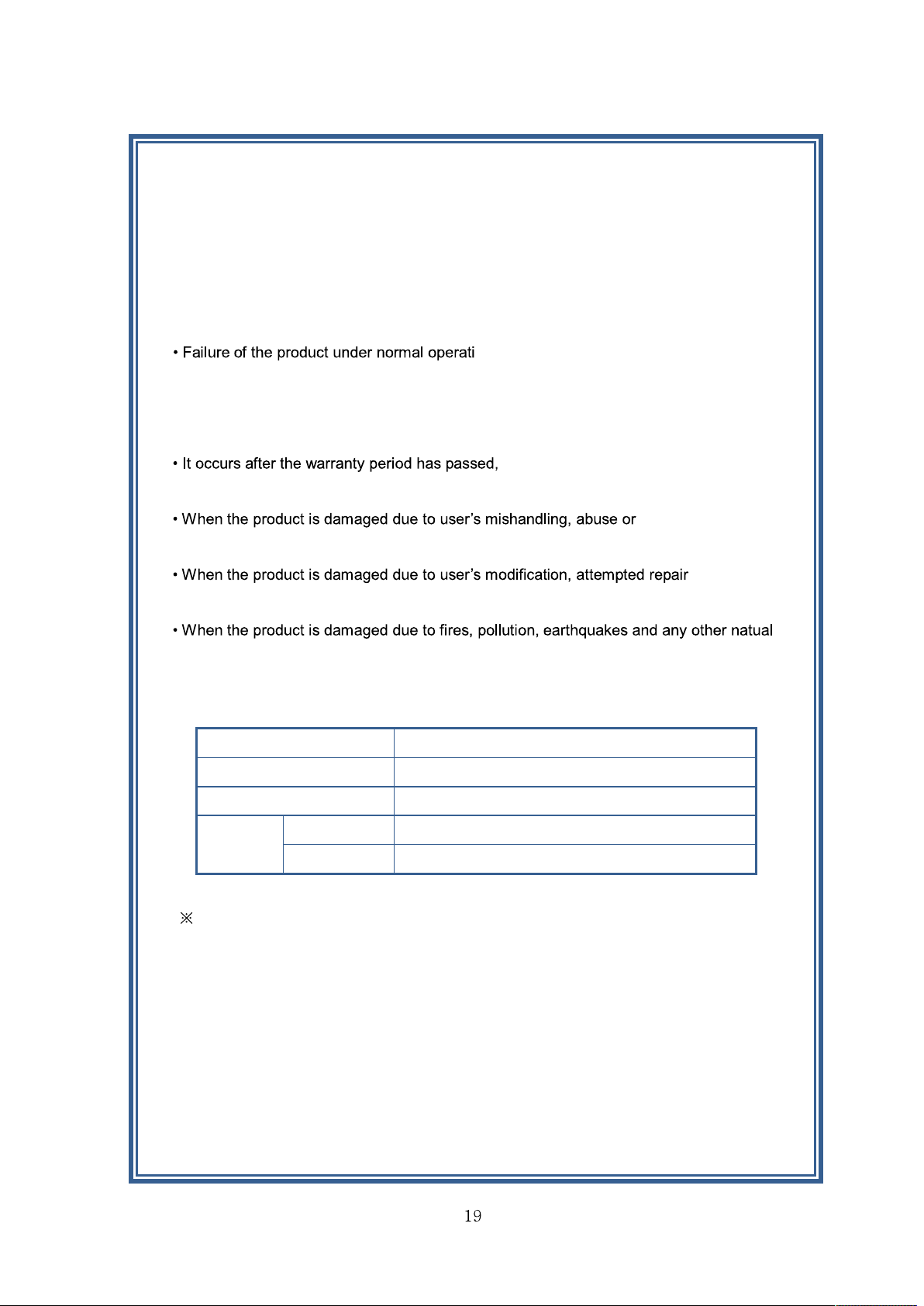
Warranty Card
Thank you for purchasing XP-100D/400D Series.
1. This product has passed strict quality control and testing process.
2. Warranty is one year from the day the factory.
ng conditions, during the warranty period
may be repaired by YeonHwa M Tech Co.,Ltd or our authorized service organization
free of charge.
3. For the following cases, some service fees will be charged.
performance failure, malfunction or
damage.
improper operation.
or otherwise access to sealed/non-user serviceable items.
or unnatural conditions, accidents, etc.
4. Product check list
Model No. XP-100D/400D
Serial No.
Purchase date
Name
Purchaser
Address
When you purchasing, please fill out this check list.
YeonHwa M Tech Co.,Ltd
36 Jeonpa-Ro, 44Beon-Gil, Manan-Gu, Anyang-City, Gyeongg-Do, Korea
Tel: 82-31-444-7270
Page 20

Output: DC12V,1A
Page 21

Page 22

Page 23

Page 24

Page 25

Page 26

Page 27

 Loading...