

Page 1
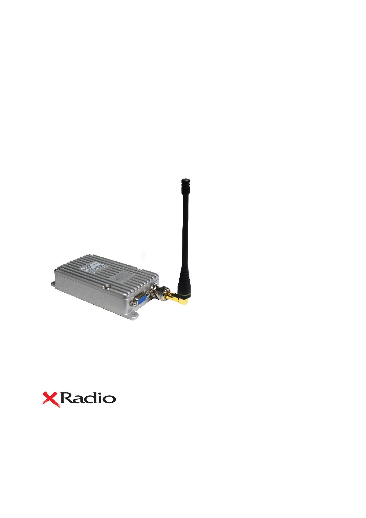
RF Audio/Data Modem
User Manual
MD-100D VHF
MD-400D UHF
1. MD-100D/400D Digital RF Modem Main Functions
The MD-100D / 400D digital RF modem has standardized the external appearance and connector
specifications to maintain compatibility with existing analog modems.
It also supports voice call and data communication with DMR transceiver and standard.
When making a voice call, use external microphone and speaker as same as existing digital radio.
It is possible to use transmitter and receiver as a single device when it is used for the village
broadcasting.
In case of data communication, it can be used as a general data modem and it is designed to use AT
COMMAND.
YeonHwa M Tech Co.,Ltd
36, Jeonpa-ro 44beon-gi l, Mana n-gu, Anyang-si, Gyeonggi-do, Korea 14086
www.xradio.co.kr Email : sales1@xradio.co.kr
Page 2

G
F
F
N
C
D
S
W
P
C
MD
MD
±1.5ppm (
1
12.5KHz
AMBE++
110mm(H) x 25mm(W) x 51mm(D)
280
DC
Receive Mode
T
Standby Mode
R
R
S
Selectivity
Spurious and Harmonic Rejection
FM Hum and Noise
A
A
A
0.25uV 12 dB SINAD
0.22uV 10dB SINAD
65dB (12.5KHz)
70dB
40dB (12.5KHz)
1Vrms
Less than
+1,
MD-100D / 400D supports dual (analog / digital) mode. It is compatible with existing analog modem or
transceiver. When using digital mode, it is very efficient in data error, clean sound quality and volume,
distance and usage time.
32 channel can be selected by using internal DIP switch.
MD-100D/400D Series main functions are below,
Frequency band - VHF : 150.8~173.4MHz, UHF: 400~470MHz.
1 Zones 32 channel selection (1zone = Max 32 channel) .
Total 32 channels can be set.
RF Power - VHF : 10 Watt, UHF : 5Watt
ETSI Standard DMR Protocol Tier1, 2
Industry Standard AMBE+2 Voice Codec
Dual mode(Digital & Analog)
Add AT Command for user convenience.
3wires continuous mode / 5wires continuous mode
Standard 1Vrms Audio Output (adjustable up to 2.5Vrms).
Carrier Detector
Encryption mode (AES128, 192, 256) - Option
RF Communication Data Speed : 9,600bps
RS-232C communication speed : standard 115,200bps(changed according to program setting)
PC-based modem Control GUI Software for user convenience
Aluminum metal Frame Body
Service Connector : DE-15 Pin Female Connec tor
Power Supp l y Voltage : DC +12V
Dimensions : 4.77”(H) x 2.44”(W) x 0.96”(D)
2. Specification
2.1 MD-100D/400D eneral Information
requency Range
requency Stability
umbers of Channel
hannel Spacing
igital Vocoder
ize
eight
ower
urrent Consumption
eceiver Specifications
eception Sensitivit y
quelch Sensitivity
udio Output
udio Distortion
udio Characteristics
-100D : 136~174 MHz
-400 : 400 ~470 MHz
-30 to +60℃)
Zones / 32 Channels
g
+12
, When using Audio – 350 mA (Audio Max)
ransmit Mode – 1,200mA
– 110mA
3%
-3 dB from 6dB per octave de-emphasis Characteristic from 300 ~ 3000Hz
Page 3

T
ransmitter Specifications
RF Output
Spurious and Harm
FM Hum and Noise
A
A
Output Impedance
VHF :
70dB
40dB (12.5KHz)
Less than
+1,
50ohms
10/2 Watt, UHF : 5/2Watt
onic
udio Distortion
udio Characteristics
3%
-3dB from 6dB per octave pre-emphasis Characteristic from 300 ~ 3000Hz
3. Specification
3.1 MD-100D/400D Overview
MD-100D/400D are digital RF modem that supports data and voice communication. It supports serial
interface, and it is set and operated with A T command, als o it can be appli ed in var ious fie lds .
3.2 MD-100D/400D functions
-. RF Communication Data Speed : 9,600bps
-. Serial Interface support (AT Command) : 115,200 bps
-. Frequency band : 400MHz ~ 470MHz
3.3 MD-100D/400D External Interface
Picture 3-1) Main Pin Specification
Picture 3-2) MD-100D/400D Digital RF Modem
Page 4

3.4 D-SUB 15Pin Connector Specification
Pin NO Pin Name
1 Not use
2 Not use
3 PTT Low Active I
4 DC12V DC+12V I
5 CTS I
6 Carrier Detector O
7 MIC_IN 30mV @ 2KHz Dev I
8 FLASH_PRO I
9 SPEAKER_OUT 300mV @ 1KHz dEV O
10 RX_DATA 3.3V TTL I
11 TX_DATA 3.3V TTL O
12 RTS O
13 GPS_TX_DATA 3.3V TTL O
Pin Description
I/O
14 Ground Ground
15 GPS_RX_DATA 3.3V TTL I
Figure 3-3) D-SUB 15PIN
Page 5

3.5 MD-100D/400D Drawing
Figure 3-4) MD-100D/400D Drawing
Page 6

4. How to set DIP Switch
Dip Switch
Power Value
DIP Switch
Binary
Channel Value
00000
1
4.1. Dip switch setting
Picture 4-1) Dip Switch TX Power setting and channel setting
4.2 TX Power Setting
TX Power is changed by Switch No.6
Factory default TX Power value is High
Low Power
High Power
Picture 4-2) DIP Switch RF Power Setting
4.3 Channel Setting
There are two ways to set the channel: DIP switch and AT command.
DIP switch channel setting method can be set by using DIP switch 1, 2, 3, 4, 5, total 32 channels.
AT Command channel setting has the following rules for the priority of the two methods.
When the power is turned on, the MD-100D / 400D operates as follows.
1) The channel is set according to the DIP switch when booting.
2) When changing channel with AT Command, DIP Switch will be ignored and return to DIP Switch
setting through AT Command (AT * DIP = 1).
DIP Switch Meaning
1 DIP Switch: Binary 5 digit
2 DIP Switch: Binary 4th digit
3 DIP Switch: Binary 3rd digit
4th DIP Switch: 2nd digit in binary
5th DIP Switch: Binary 1st digit
Below is the channel table according to DIP Switch status.
Page 7

00001
2
00010
3
00011
4 00100
5
00101
6
00110
7 00111
8
01000
9
01001
10 01010
11
01011
12
01100
13 01101
14 01110
15 01111
16 10000
17 10001
18 10010
19 10011
20 10100
21 10101
22 10110
23 10111
24 11000
25 11001
26 11010
27 11011
28 11100
29 11101
30 11110
31 11111
32
5. MD-100D/400D Operation Mode
MD-100D / 400D su pports 3 modes : 1) AT Command mode and 2) continuous m ode for k eyboard input
or file transfer using Tera term.
Page 8

MD-100D/400D operat ion mode
Description
MD-100D/400D Operation Mode Setting
AT*CMODE=*
“CMODE OK”
3WIRES
OFF
AT*CMODE=3WIRES
Select the required mode from above
Description
Command to check the modem version
Query
Answer
AT*VERSION
*VERSION:<value>
Parameters
AT*VERSION
OK
Description
Command for reset the modem
Query
Answer
AT*RESET
RESET
Parameters
AT*RESET
Going down terminal…
Description
Command for sending a message
Query
Answer
AT*MSG=<value>
OK
AT*MSG=AA
OK
Description
Command for the checking or set the modem volume
Query
Answer
AT*VOL?
GET VOLUME(<value>)=(<value>)
1) AT Command mode
2) 3 Wires continuous mode
-. Operates in 3 Wire Mode (TXD, RXD, GND).
3) 5 Wires continuous mode (used for many data transmission)
-. Supports H / W flow control using TXD, RXD, CTS, RTS, GND.
When the MD-100D / 400D data modem is booted for the first time, AT Command mode is set.
To change from AT Command mode to Continuous mode, use AT Command as shown below.
Query
Answer
Parameters
Example
“CMODE : *
5WIRES
AT*CMODE=5WIRES
AT*CMODE= OFF
6. AT Command interface
Set the status of MD-100D/400D or user AT Command for function operation. The serial Speed is
115,200 bps.
6.1 VERSION
Example
6.2 RESET
*VERSION:YEONHWA Modem v1.0
Example
RESET
6.3 MSG
Parameters
Example
문자열
6.4 VOL
Page 9

AT*VOL=<value>
SET VOLUME(<value>)=(<value>)
Parameters
1 ~ 16
AT*VOL?
SET VOLUME(5)=(47)
Description
Command for checking OWN ID
AT*OID?
OK
Parameters
AT*OID?
OK
Description
Status check command
AT*CHKSTAT?
OK
Parameters
AT*CHKSTAT?
OK
DIP switch is ignored whe n setting the channe l with AT Comm and. If
DIP Switch operation
AT*DIP?
OK
1: Channel setting using DIP Switch
0: Channel setting using AT Command
AT*DIP?
OK
Call ID check and setting command
D set in CPS tool. You can
change the Call ID with this command, and when changing the
channel, it will be reset to the Call ID set in the CPS tool.
Query
Answer
AT*CID?
CUR-CID:<call id>,CF:<call format>
GET VOLUME(15)=(150)
Example
AT*VOL=5
6.5 OID
OWN ID setting is available only in CPS program, and can be checked in AT Command only.
Query
Answer
Example
6.6 CHKSTAT
Query
Answer
Example
6.7 DIP
Description
Query
Answer
OID:00000001
OID:00000001
*CHKSTAT:STAT OK
*CHKSTAT:STAT OK
you want to change th e channel using the DIP switch aga in, you can
use this comm and to chan ge the ch annel so th at it ca n be chan ged b y
*DIP=<value>
OK
AT*DIP=<value>
*DIP SET=<value>
Parameters
*DIP=1
OK
Example
AT*DIP=<value>
*DIP SET=<value>
6.8 CID
Description
Basically, it communicates with Call I
Page 10

CID[<index>]:<call id>,CF:<call format> [반복]
CALLID OK
Parameters
Example
AT*CID?
CALLID OK
Channel setting command (When this command is used, channel value
changed by DIP Switch is ignored.)
AT*CHSET=<channel number>
CH:<channel number>:<Channel type>,RX:<RX Frequency>,<RX
OK
Parameters
AT*CHSET=1
OK
Description
Show channel list command
AT*CHLIST?
OK
Parameters
AT*CHLIST?
OK
Description
Current setting parameter display command
AT*MINFO?
OK
Parameters
AT*MINFO?
OK
Description
Power Level Setting
6.9 CHSET
Description
Query
Answer
CALLID OK
AT*CID=1
SET CUR-CID:01
CID[01]:00000002,CF:GRP
CID[00]:00000001,CF:GRP
CID[01]:00000002,CF:GRP
CID[02]:00000003,CF:GRP
CID[03]:00000010,CF:GRP
CID[04]:********,CF:ALL
CC>,TX:<TX Frequency>,<TX CC>
Example
6.10 CHLIST
Query
Answer
Example
6.11 MINFO
CH:01:DMR,RX:41050000,01,TX:41050000,01
CUR-CHNUM:<Current channel number>
<number>:<Channel type>,RX:<RX Frequency>,<RX
CC>,TX:<TX Frequency>,<TX CC> [반복]
CUR-CHNUM:04
00:DMR,RX:40550000,01,TX:40550000,01
01:DMR,RX:41050000,01,TX:41050000,01
02:DMR,RX:41550000,01,TX:41550000,01
03:DMR,RX:42050000,01,TX:42050000,01
04:DMR,RX:42550000,01,TX:42550000,01
Query
Answer
6.12 PWRLEVEL (Power Level)
Example
*MINFO:<channel index>,<Radio type>,RX:<RX
Freq>,<CC>,TX:<TX Frequency>,<TX CC>
OID:<Own ID>,CID[<Call ID index>:<Call ID>,CF:<Call format>
*MINFO:04,DMR,RX:425500000,01,TX:425500000,01
OID:00000001,CID[00]:00000001,CF:GRP
Page 11

It is set according to Dip sw itch 6 at boot, and it c an be changed with
this command.
Query
AT*PWRLEVEL?
OK
0 : Low Pow er
1 : High Power
AT*PWRLEVEL?
OK
Description
Command to check the modem version
Query
Answer
AT*VERSION
*VERSION:<value>
Parameters
AT*VERSION
OK
Answer
Parameters
Example
6.13 VERSION
GET PWRLEVEL=<value>
OK
AT*PWRLEVEL=<value>
SET PWRLEVEL=<value>
GET PWRLEVEL=0
OK
AT*PWRLEVEL=1
SET PWRLEVEL=1
Example
*VERSION:YEONHWA Modem v1.0
1. AT Command Data Configuration
AT*MSG= ASCII Data(80 byte) 0D0A
2. Structure to send text documents using Tera Term wirelessly
1) RS-232C Serial Buffer of MD-100D/400D (Data Modem) has a total of 10 Kbytes.
Each buffer stores 80 bytes of data.
2) Serial transmission Timer transmits maximum 80 bytes after 120msec received buffer check.
-. To improve performance, the Serial Transfer Timer can be reduced by 120msec, and the amount
of data transferred can be increased or decreased.
-. Currently, the amount of data transferred is fixed at 80 bytes.
3) Therefore, if you use a pr ogram like Tera Term to input characters on the k eyboard, it will be s ent
immediately upon input.
4) You can also transfer files using Tera Term.
Page 12

2) AIR data transfer structure
Since the DMR Data Modem operates in 2: 1 mode, the actual transmission is as follows.
2:1 TDMA : There are two slots (slot1, slot2(30m/s) in a single channel so it operates as the below
picture.
Figure 2: 1 TDMA structure
3. How to use RS232 / RS422 / RS485 / USB / GPIO / Ethernet connection
4. Did you use CTS and RTS for the cable?
1) The serial buffer of MD-100D/400D is 10 Kbyte. If you want to transf er a lot of data ( when the amount
of data exceeds 10Kbyte), you should use 5-wire serial communication method as below.
Because the RS232 Speed is 115.2 00bps and the tra nsmission speed of the wireless secti on is slower
as 9,600bps, memory management must be done in the serial buffer.
Page 13

When RTS is "LOW" (when the MD-100D/400D mod em's serial buffer has space): The PC or external
device sends normal serial data to the modem.
When RTS is "High" (when the serial buffer of the MD-100D/400D m odem is f ull): it stops se nding ser ial
data to the external device.
When CTS is "LOW ", data received b y modem is transm itted to PC or ext ernal d evice. If it is HIG H, data
is not transmitted to PC or external device.
Page 14

5. D-SUB 15Pin Change connector specification
→
→
Figure D-SUB 15 PIN
1) 5 Pin : GPIO1
2) 12Pin : SERIAL_BUSY
Pin NO Pin Name
1 Not use
2 Not use
3 PTT Low Active I
4 Vin(DC12V) DC+12V I
5 GPIO1 → CTS I/O→I
6 Carrier Detector O
7 MIC_IN 30mV @ 2KHz Dev I
8 FLASH_PRO I
9 SPEAKER_OUT 300mV @ 1KHz dEV O
10 RX_ D ATA 3.3V TTL I
11 TX_DATA 3.3V TTL O
12 SERIAL_BUSY → RTS I/O→O
13 GPS_TX_DATA 3.3V TTL O
14 Ground Ground
15 GPS_RX_DATA 3.3V TTL I
CTS
RTS
Pin Description
(Not use CTCSS/DCS)
(Not use CTCSS/DCS)
I/O
I
O
Page 15

5. For Safe Operation
•
Do not give an excessive shock to the radio.
5.1 Precautions
Do not remove the antenna from the radio or do not transform the antenna or
do not make any changes on the antenna. The strong electronic wave to be
emitted from the radio can have an effect on the performance of the radio and
can cause the radio to have a defect.
Do not use accessories (such as rechargeable battery, adaptor, external
speaker microphone and earphone etc.) from the other makers, which can
cause defect on battery and malfunction or a defect on the radio.
Do not disassemble or reorganize the radio. The disassembly or reorganization
will cause a defect or malfunction on the radio. It will be impossible to repair
afterwards. There will also be a punishment made by the Radio Waves Act.
Do not use other frequency except for the permitted frequency in order not to
be punished by the Radio Waves Act.
•
Do not place the radio where the direct sunlight and/or the high temperature
occurs..
•
If the radio is placed for a long time in a car in summer, the hot temperature in
the car may cause explosion of battery.
•
Do not make a damage to the battery by a sharp substance and/or an
excessive shock.
5.2 Influences on the Operations of Radio or Other Equipment
The radio emits a strong electronic wave, which may have an effect on the operation of oth
er
equipment and also can be influenced by the other devices.
Please turn off the radio before boarding on the airplane.
When using the radio in the airplane, please follow the rules or the instructions
of the flight attendants.
In case of the area that medical equipment are being used, please use the
radio after discussion with the equipment producer or the related doctor.
Page 16

Please do not use the radio at the place where computer or other
electric/electronic devices are being used. The strong electronic wave from the
radio can have an effect on the equipment.
6.
Safety Notes
Please make sure to read the followings above for safe and effective use of the radio.
•
An indication of the maximum antenna gain permitted to ensure compliance.
this would be 1.5 dBi.
•
At the area where an electromagnetic force can be made, please make sure
to turn off the power of the radio.
•
The user should limit the operation to 50%.
•
RF Safety Distance on page 13 to match with RF exposure exhibit: 13.21cm for
Occupational / Controlled, and 29.46cm for General / Uncontrolled.
•
Be careful that if the outer surface of the antenna is peeled off, there is a
danger of a topic.
7.
Handling Caution
•
Any changes or modifications not expressly approved by the party responsible for compliance with the FCC
regulations could void the user's authority to operate the equipment.
•
It is forbidden to install or operate the device other than the responsible person (licensed person).
•The user manual is included in the box.
•How to use and install the product is shown in the figure.
Page 17

Application
8.
Usage
▪
Water/Waste Treatment
▪
Plants Oil and Gas Field, SCADA
▪
Security/Alarm System
▪
Gate Systems, Remote Controls
▪
Commercial Sign Control
▪
Automatic Vehicle Location
▪
Murphy/Kill Switches
▪
Weather Monitoring
▪
Irrigation Systems
▪
Emergency Call Boxes
▪
Low Power Repeaters
Page 18

Model Name
MD-Series
Serial No.
Purchase Date
Name
Address
W ar ranty Statement
Thank you for purchasing MD-100D/ MD-400D Series.
1. This product has passed strict quality control and testing process by YeonHwa M Tech.
2. Warranty is one year from the day of release.
• When there is malfunction of the product under normal operating conditions during the
warranty period, your authorized dealer and the service center will repair it free of charge.
3. Service fees will be charged for the following cases:
• When performance failed, malfunction or damaged after the warranty period.
• When the product is damaged due to user’s mishandling or improper operation.
• When the produc t is damaged due to fire, pollution, earthq uakes and an y other natural or
unnatural conditions, accidents etc.
• Malfunction by not keeping the notices written in the user manual.
• Malfunction by not using the appointed adaptor.
• When the product is damaged due to us er ’s modif ication, attem pts of repairing rather than
the appointed service center.
4. Product Check List
Purchaser
※
Please fill out this check list when purchasing the product.
YeonHwa M Tech Co., Ltd.
36, Jeonparo 44beongil, Manan-gu, Anyang-si, Gyeonggi-do, Korea 14086
TEL: 82-31-444-7270
FAX: 82-31-444-7271
 Loading...