

Page 1
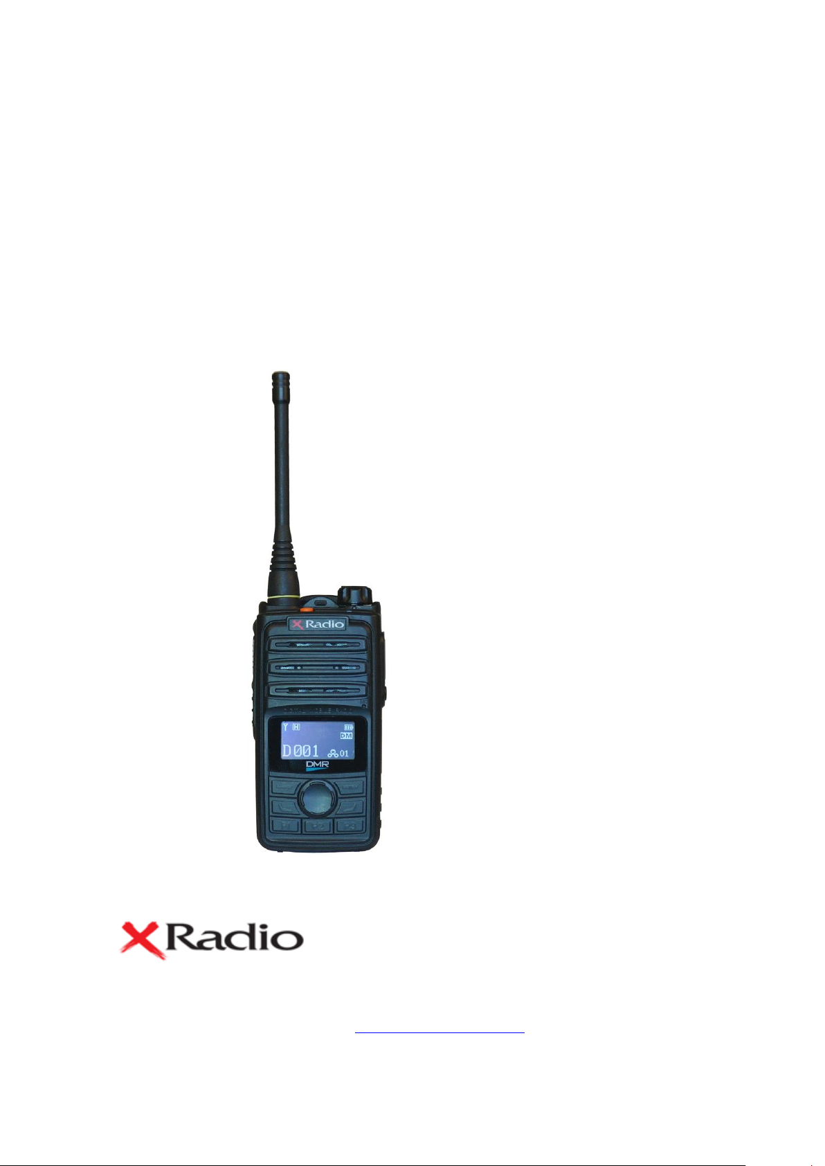
DX-6000 Series
User Manual
VHF Transceiver
DX-6100
DX-6200
UHF Transceiver
DX-6400
Version #1 (2019-03-25)
Yeon Hwa M Tech Co.,Ltd.
36, Jeonpa-ro 44beon-gil, Manan-gu, Anyang-si, Gyeonggi-do, 14086, Korea
Tel : 82-70-7436-3296 / E-mail : saleshan@xradio.co.kr / Web : www.xradio.co.kr
Page 2

2
1. DX-6000 series features
DX-6000 series is designed to provide ease of use the functions of digital radio and it is an
easy grip radio for the hand. It’s developed for the consumer safety and convenience in
complex public places such as military, fire department, construction, industrial field. In addition,
it works in dual (analog/ digital) mode and is compatible with existing analog radio currently.
Digital mode is made up for analog radio’s weaknesses such as sound quality, call distance,
and usage time.
The main functions of DX-6000 series are as follows
64 Zones 1024 channels selection (1zone = Max 1024channels)
The total number of channels can be set up to 1025 channels
4.8/1 Watt RF Power
Send/ receive text messages (up to 40 characters), up to 10 sentences
Encryption Mode (AES128. 196. 256)
TX Interrupt
Lone Worker
Man down function(optional)
BCL / BCLO
Time-Out Timer (TOT)
Emergency / siren function
Built-in flash lamp
Vibration(optional)
Voice recording and playback
Mixed channel(analog / digital0
GPS (optional)
5 levels VOX(Voice Operated Transmit)
5 levels S.Q selection (support analog radio).
Remote Radio Stun / Kill / Revive
1Watt audio output
UDC accessory connector for waterproof(IP67)
OLED Display
DC+7.2V Li-ion / 2,600mAH High capacity battery
Page 3

3
2. Specification
General
Frequency Range
Frequency Stability
Programmable Channels
Channel Spacing
Digital Vocoder
Dimensions
Weight
Power Source
Current Drain (maximum)
DX-6100 : 136~174 MHz
DX-6200 : 245~254 MHz
DX-6400 : 400 ~510 MHz
±1.5ppm (-30 to +60℃)
16 Zones / 32 Channels
12.5KHz
AMBE++
103mm(H) x 52mm(W) x 32mm(D)
280g
DC +7.2V Li-ion 2,600mAH Battery
Receive mode, rated audio out – 420 (Audio Max)
Transmit mode – 1,200mA
Standby mode – 110mA
Receiver
Sensitivity
Squelch Sensitivity
Selectivity
Spurious and Harmonic Rejection
FM Hum and Noise
Audio Output Power
Audio Distortion
Audio Response
Input Impedance
0.20uV 12 dB SINAD
0.18uV 10dB SINAD
65dB (12.5KHz)
75dB
40dB (12.5KHz)
1 Watt across an 8-ohm load
Less than 3% at rated output
+1, -3 dB from 6dB per octave de-emphasis Characteristic from 300 ~ 3000Hz
50 ohms
Transmitter
RF Power Output
Spurious and Harmonic
FM Hum and Noise
Audio Distortion
Audio Frequency Response
Output Impedance
DX-6100 : 5/1Watt
DX-6200 : 4.8/1Watt
DX-6400 : 5/1Watt
70dB
40dB (12.5KHz)
3% maximum with 1KHz modulation
+1, -3dB from 6dB per octave pre-emphasis Characteristic from 300 ~ 3000Hz
50ohms
2.1 DX-6000 Series
Page 4
4
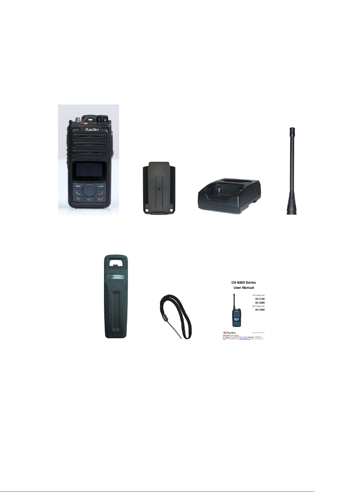
3. DX-6000 series accessories
* The accessory parts may be changed at the request of the buyer
Main body Battery 2unit charger Antenna
Belt Clip Hand strip User manual
Figure 3-1) DX-6000 series main accessories
Page 5
5
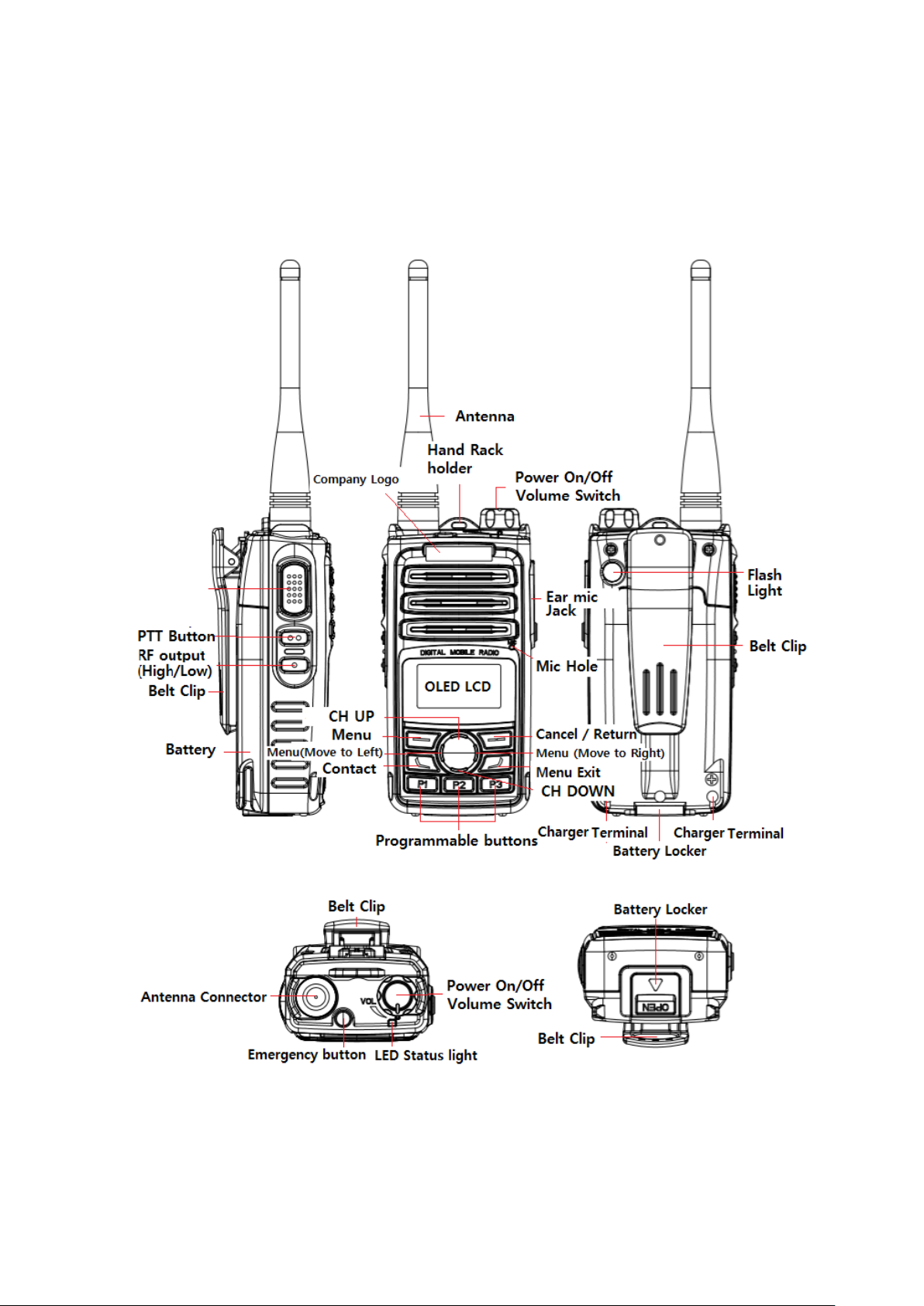
3.1 DX-6000 series exterior view
Figure 3-2) DX-6000 series exterior view and control buttons
Page 6
6
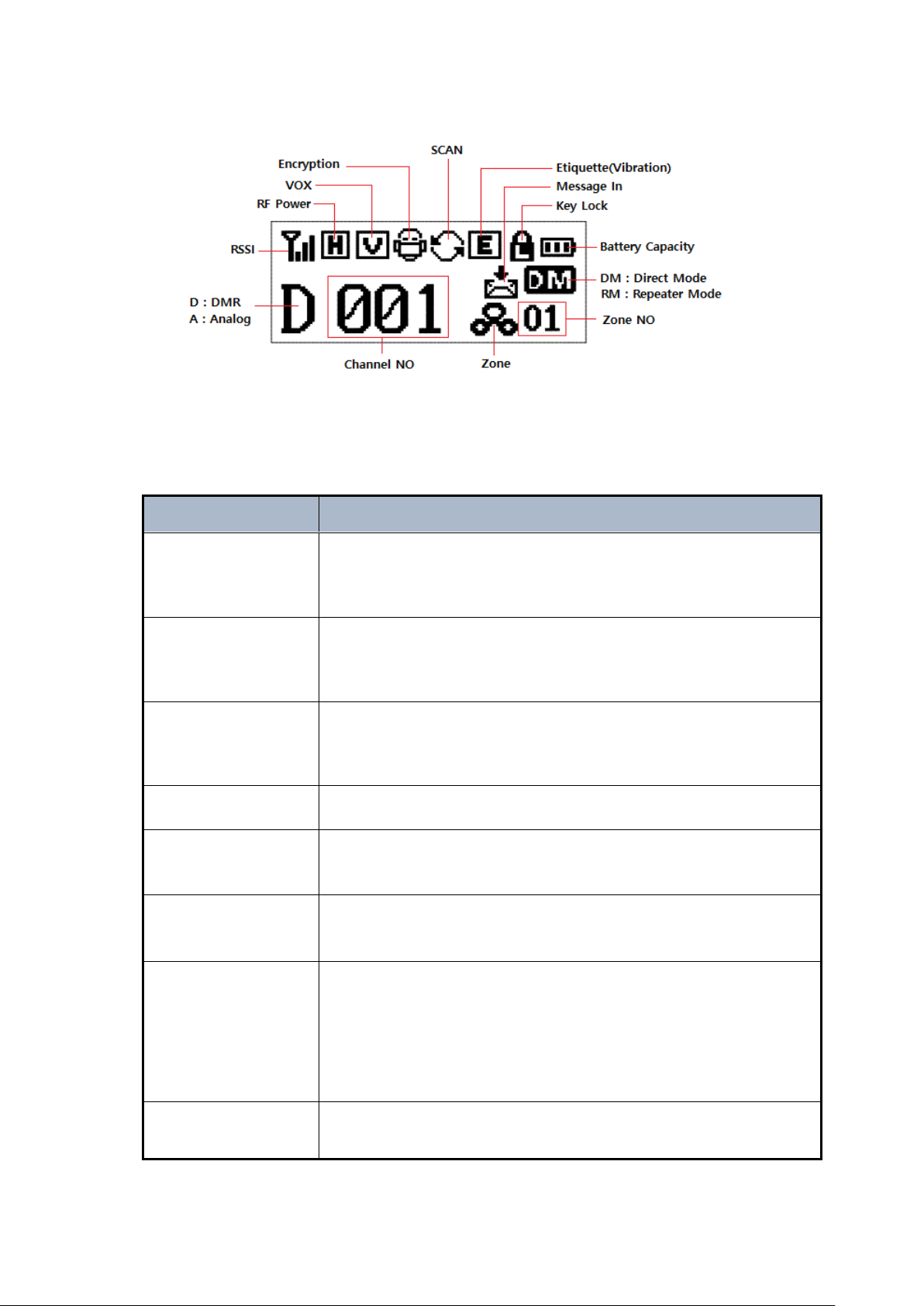
Figure 3-3) DX-6000 series LCD icon explanation
Button
Description
Power On/Off
volume switch
Turning the power On/Off volume switch clockwise, the radio is turned on
and the volume is louder. Turning the power On/Off volume switch
counterclockwise, the radio is turned off and the volume is decreased.
Volume/
Menu +/- button
By using +/- buttons to adjust the call volume. Press the + button to
increase the volume and the – button to decrease the volume.
*In the menu state, the user can move the menu items.
Up/Down button
The user can change the setting for the set channel. 32 channels can be
put in per each zone.
*In the menu state, the user can move the menu items.
Zone button
The user can change the calling areas in order.
Menu/OK button
The user can enter the menu with this button and select the menu items.
Cancel/Return button
While entering the menu, use the button to return the upper menu. The
user can cancel from the menu setting screen.
P1, P2, P3 button
Programmable Key when operating with Short Key.
Long Key (press longer than 2secs),
- P1 is Lock / Unlock the button lock function
- P2 is Flash On/ Off operation
- P3 is etiquette On / Off operation
Contact List button
It is a button to enter directly into Contact List. The user can enter Private
Contact, Private Call, Group Call or All Call.
3.2 Basic operation description
Page 7

7
4. How to operate the basic functions
1. Do not over tighten the antenna as it may cause damage to the radio
2. NEVER HOLD by the antenna when carrying the transceiver.
3. Transmitting without an antenna may damage the transceiver.
Please read the instruction manual thoroughly before using the product.
This manual provides useful information related to the operation of the radio.
4.1 Antenna installation and Removal
Turn the antenna clockwise to tighten the antenna and counterclockwise to loosen the antenna
as the Figure 4-1.
Figure 4-1) How to tighten and loosen the antenna from the radio
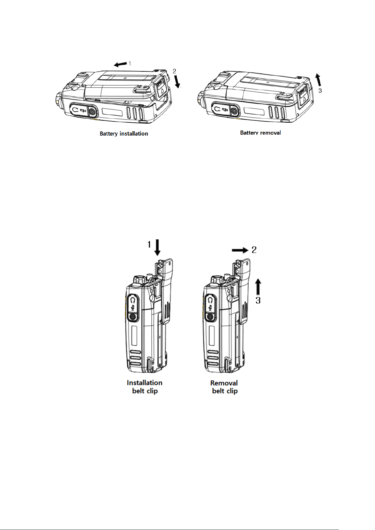
4.2 Battery installation and Removal
As shown the figure 4-2, align the battery pack with the groove of the body and push it in the
direction 2 to attach the battery. For removing the battery, push the battery locker and pull it
in the direction of arrow 3 to remove the battery from the radio.
Page 8
8
Figure 4-2) How to install and remove the battery
4.3 Belt Clip Installation and Removal
As shown the figure 4-3, align the on the belt clip holder and push it in the direction 1. For
removing the belt clip, push the belt clip locker in the direction 2 and pull the belt clip in the
direction 3.
Figure 4-3) How to install and remove the belt clip
4.4 External Accessory Connector Jack
When connecting the external accessories, as show in the figure 4-4, align the main unit and
the accessories, then push the accessories while pulling out the accessories.
Page 9

9
Figure 4-4) External accessory connector jack
4.5 How to charge the battery
RED lamp indicates the radio is on the charger (XC-200D) that the unit is staring to charge and
the LED will illuminate GREEN when the charging is completed. XC-200D is developed as the
double-ended to charge the main body and the battery pack itself.
When the main body of the radio and the battery packed are charged at the same time, the
main body will be charged first then when charging is completed, the battery pack will be
charged.
Figure 4-5) How to charge the battery
Page 10

10
5. Operation of the radio
DX-6000 series body buttons are defined as shown the figure 5-1.
Figure 5-1) DX-6000 series button definitions
5.1 Power ON/OFF Volume Switch
Turning the volume switch to the right to turn on the LCD with the start-up sound and turn the
radio on. Turning the power ON / OFF switch to the left while the radio is on will turn off the
power with the message "Goodbye". To increase the volume sound, turn the volume switch
clockwise and to decrease the volume sound, turn the volume switch counterclockwise.
5.2 PTT Button
Press the PTT button to enter the transmit mode and release it to receive mode. To transmit
good sound quality, it is recommended to keep a distance of about 5 to 10cm from the
microphone.
5.3 ZONE Button
Pressing the ZONE button will select the zones registered in the program in order. The user
can use the channel UP / DOWN buttons to select the channel in the selected zone.
Page 11

11
5.4 Menu Button
After pressing menu button, press right button of the menu screen, the menu appears as
shown in Fig. 5-2). Press the move button to move to the left and press the Menu button again
on the selected menu to enter the detailed menu.
Figure 5-2) DX-6000 series menu
Figure 5-3) DX-6000 series menu tree
5.5 Channel Menu UP/Down Button
Channel menu UP / Down button operates as normal channel UP / Down button and also it
operates as menu UP / Down selection function when entering menu mode.
5.6 Contact Button
Press Contact button to enter connection mode such as Individual, Group, All Call registered in
Contact menu.
Page 12

12
5.7 P1, P2, P3 Programmable Button
P button Key
Short Key
Long Key
P1
Programmable
Key Lock ON/OFF
P2
Programmable
Flash Light ON/OFF
P3
Programmable
Vibration mode ON/OFF
The P button performs two actions as Short Key and Long Key (pressing longer than 2 seconds).
The Short Key can be used to configure the functions in the PC program.
Key Lock is automatically set when there is no input information for 10 seconds. If you want to
cancel the Key Lock function, press the P1 key with the Long Key to cancel and use all the keys.
If there is no input information for 10 seconds, Key Lock mode will be activated automatically
again. To cancel the key lock completely, turn off the Key Lock Menu in the setup menu, and
the Key Lock function is canceled.
5.8 UDC EAR/MIC Jack
The UDC EAR / MIC jacks are jacks for use with external speaker microphones, CPS program
setting, radio firmware upgrading, and communication with external devices.
5.9 LED Status Sign
This LED indicates the operation status of the radio. The main status notation is as follows.
① Red at normal transmission
② Green at normal reception
③ When the frequency is correct but the color code does not match, it will blink green if
not received.
④ In case of low battery, red light flashes and with an alarm sounds.
Page 13

13
6. How to charge the battery
Charging in a third party charger will cause damage to the battery as
well as damage to the unit.
Continuous rapid discharge (when the positive or negative terminal of
the battery touches the metal object) will cause a fatal defect in the
battery and may cause the battery to explode or cause a fire.
Status
LED Indication
Status
LED Indication
Charging
Red LED lights
Error Detection
Red LED flickers
Complete
Charging
Green LED lights
Keep Charging
Green LED Appears
6.1 Precautions
1) The DX-6000 series uses a large-capacity Li-ion battery (XB-2600). The battery is safe and
highly reliable, the standard charger allows you to fully use the battery's efficiency and life.
2) For optimal capacity and safe operation of the device, please charge the battery before use.
3) When charging the battery with the wireless device, make sure to turn off the power.
6.2 Battery Charge
When the battery voltage drops, the communication distance becomes shorter and the
performance of the radio cannot be maximized. Charge the battery in the following conditions.
1) When it is judged that the battery capacity has decreased.
2) When the red lamp on the front of the product flashes during transmission or reception
(0.5sec cycle)
3) When the battery indicator icon blinks
4) When low battery alarm sound occurs during use
6.3 How to charge the battery
1) Plug the adapter of the XC-200D charger into the AC220V power outlet.
2) When charging the radio equipped with the battery, turn off the power completely and
insert it into the charger.
3) Even if the green lamp is turned on after the charging is completed, keep charging for
about 30 minutes for full charging.
Page 14

14
7. DX-6000 series radio operation
7.1 Menu functions
To enter the menu tree, press button. There are 8 main menus in menu mode. The user
can use the radio more conveniently if the user set it according to usage purpose and
environment.
Figure 7-1) DX-6000 series main menus
☞ Note) If the menu is not operated for at least 25 seconds after launch, the radio will revert
to standby mode.
7.1.1 Contact
Select the transmission contact (set by CPS program) and press the PTT button to make a call.
If a user wants to make a call with another registered contact, select the contact in the contact
list and press the PTT button to make the call.
Contact lists in the menu can be registered / deleted using CPS (Customer Programming
Software) program.
When the user select into the contact menu, the list is displayed divided into individual, group
and All Call contacts.
ICONs shown in contact list
- : Individual contact list (individual calls, individual messages can be sent)
- : Group contact list (group call, group message can be sent)
- : All contact lists (terminals with the same channel and color code are available)
7.1.2 Messages
When a new message arrives in the receive mode, the message contents are displayed on
the LCD and enter the menu mode. When a new message arrives at another operation, it will
be displayed as ICON.
The Message menu provides three additional menu functions: Quick Message, Inbox, and
Outbox.
1) Quick Message
Page 15

15
By using the CPS program, the user can register total 10 messages and 1 message can
be edited up to 40 characters.
The user can see the registered message by selecting the simple message menu, select
the message the user wants to send, and press button to view the message
contents.
Press button again to send the selected message to the registration terminal.
2) Inbox.
A maximum of 10 messages can be received from the inbox. A user can view the
received messages by selecting the contents stored in the list.
If 10 received messages are maximum and more than 10 received messages are deleted
first. If a user wants to delete the received message, you can delete the entire message
by selecting the Delete All menu.
3) Outbox.
The maximum number of messages in the Outbox can total 10. The user can view the
messages that have been sent by selecting the contents stored in the list.
The number of outgoing messages is managed as 10, and the number of outgoing
messages is cleared and received first. If a user wants to delete the outgoing message,
the user can delete the whole delete menu.
7.1.3 Call Logs
Call Logs menu stores only the history of individual calls. Group, All call are not saved. The
messages are managed by the message inbox and outbox.
1) Inbox
The user can store 10 call histories in total. The stored contents in the list show the ID of
the receiving party.
Inboxes are managed with a maximum of 10 call histories, and if more than 10 histories
are received, automatically deleted the call history which registered the first. The user can
delete the entire call histories in the Delete Menu.
2) Outbox
A total of 10 call histories can be stored in the Outbox. The contents stored in the list
can see shows the ID of the called party.
The number of outboxes is managed as 10 call histories, and if the number is more than
10 call histories, automatically deleted the call history which registered the first. The user
can delete the entire call histories in the Delete Menu.
Page 16

16
7.1.4 Record
When the encryption mode is selected, only encryption mode call is
recorded, and if encryption mode is not selected, normal call contents
cannot be heard.
Call recording is a function to save the contents of outgoing and incoming calls. If a user
does not need the recorded contents, the user can delete it all.
The user can save up to 63 calls and single call is limited to 2 minutes and 30 seconds.
The user can use the call recording function, select it on the setting menu.
7.1.5 Scan
When the user turns on the scan operation in the scan menu, scanning starts in the order of
the channels set in the scan list. If there is a channel being used during scanning, it will stop on
that channel and receive its contents. If a user wants to make a call while scanning, set it on
the CPS program.
1) Scan ON/OFF
A user can set scan function on/ off in the Menu
2) Scan list
The scan lists can be set on the CPS program.
7.1.6 ZONE
Zones are created up to 16 zones and each zone can be registered 32 channels. Use the CPS
program to set the zones.
7.1.7 Setting
This menu is used to set various statuses of the radio. Settings include transmission output,
voice encryption, VOX, Lone Walker, BCL / BLCO, keypad lock, sound, backlight, clarity, LED
settings, and language.
1) Transmission power
Set the high and low of the transmission power.
2. Voice Encryption
Page 17

17
This is a feature to encrypt the incoming and outgoing voice. Voice Encryption function can
be set for each channel from all of the digital channels.
The setting of voice encryption code is using the CPS program, the total number of
encryption can be set from 0 to 65535.
3. VOX
VOX function is transmitted by detecting a voice level without using the PTT button
VOX sensitivity level is 1 - 5 steps, you can set using the CPS program.
4. Lone walker
It is function to inform others about your safety within the time set in the menu.
Setting time supports up to 1-100 minutes.
5. BCL/BCLO
If the another user on the currently used channel, it is the ability to limit the transmission so
as not to interfere.
BCL: If the current channel is busy, the transmission prohibition
BCLO: The ability to send regardless of the user of the current channel
6. Button Lock
With the exception of the minimum of buttons necessary for the user to prevent unwanted
terminal operation, it is the ability to limit the operation.
When the button lock function is on, all buttons are locked except the PTT button, the
emergency button and power ON / OFF button.
7. Tones
This is a Tone setting function. The main menu is available only ON / OFF.
The detailed sound can be set using the CPS program.
8. LCD BACKLIGHT
This feature is LCD backlight ON / OFF.
9. LCD Contrast
The function is to adjust the brightness. The brightness can be set from 1 to 7 step.
10. LED Control.
The feature is to set the LED status display. It can be set detailed using the CPS program.
Page 18

18
11. Language
The feature is to select the language for the menus.
7.1.8 Radio information
A menu that shows the information in this device.
Page 19

19
8. Precautions
Don’t remove the antenna from the Radio or don’t transform the antenna or
don’t make any change on the antenna. The strong electronic wave to be
emitted from the Radio can have an effect on the performance of the Radio and
can cause the Radio to have a defect.
Don’t use the accessories (such as rechargeable battery, adaptor, external
speaker microphone and earphone, etc.) from the other makers, which can
cause to make a defect on battery and a malfunction or a defect on the Radio.
Don’t disassemble or reorganize the Radio. The disassembly or reorganization
will be causes of defect or malfunction and it will be impossible to make repair
afterward. Also, a punishment can be made by law.
Don’t use the other frequency except for the permitted frequency in order not to
be punished by law.
• Don’t give an excessive shock to the Radio.
• Don’t place the Radio where the direct sunlight and/or the high temperature
occurs.
• If the Radio is placed for a long time in car in summer, the hot temperature in
the car may cause an explosion of battery.
• Don’t make a damage to the battery by a sharp substance and/or an
excessive shock.
Please turn off the Radio before boarding on airplane.
When you want to use the Radio in the airplane, please follow the rules in the
airplane or the instructions by crew.
In case of the area that medical equipments are being used, please use the
Radio after discussion with the equipment maker or the related doctor.
Please don’t use the Radio at the place where computer or the other
electric/electronic devices are being used, because the strong electronic wave
from the Radio can have an effect on the equipment.
8.1 Matters affecting the performance of the equipment.
8.2 Influences to the operations of Radio or other Equipment.
The Radio emits a strong electronic wave, which may have an effect on the operation of other
equipment and also, can be influenced by the other devices.
Page 20

20
9. Safety Notes
• Please keep the Radio away at least 1inch from the body.
• If the outside surface of antenna gets stripped out, it can make a burn on the
skin.
• If you contact a conductive metal to battery terminal, a heat can be made and
it may cause fire, explosion and burn. Especially, please be careful when
putting the battery in a pocket or a bag.
• When using an earphone, please don’t listen to the sound at a high level. The
high sound may have a bad effect on your ear.
• After setting the volume of the Radio at a low level, please adjust the volume
step by step to the level you want. A sudden high sound may give a bad
damage to the ear or the heart.
• Please don’t remove or replace or charge or discharge the battery at a
dangerous area, since it may cause an explosion or a fire by an electrical
spark.
• At the area where an electromagnetic force can be made, please make sure
to turn off the power of the Radio.
Please make sure to read the followings for safe and effective use of the Radio.
Page 21

21
Warranty Card
Thank you for purchasing DX-6000 Series.
1. This product has passed strict quality control and testing process.
2. Warranty is one year from the day the factory.
• Failure of the product under normal operating conditions, during the warranty period
may be repaired by YeonHwa M Tech Co.,Ltd or our authorized service organization
free of charge.
3. For the following cases, some service fees will be charged.
• It occurs after the warranty period has passed, performance failure, malfunction or
damage.
• When the product is damaged due to user’s mishandling, abuse or
improper operation.
• When the product is damaged due to user’s modification, attempted repair
or otherwise access to sealed/non-user serviceable items.
• When the product is damaged due to fires, pollution, earthquakes and any other natual
or unnatural conditions, accidents, etc.
4. Product check list
Model No.
DX-6000
Serial No.
Purchase date
Purchaser
Name
Address
※ When you purchasing, please fill out this check list.
YeonHwa M Tech Co.,Ltd
36 Jeonpa-Ro, 44Beon-Gil, Manan-Gu, Anyang-City, Gyeongg-Do, Korea
Tel: 82-31-444-7270
Page 22

22
FCC statement
This device complies with Part 15 of the FCC Rules. Operation is subject to the following two co
nditions: (1) this device may not cause harmful interference, and (2) this device must accept any
interference received, including interference that may cause undesired operation.
Changes or modifications not expressly approved by the party responsible for compliance
could void the user's authority to operate the equipment.
NOTE: This equipment has been tested and found to comply with the limits for a
Class B digital device, pursuant to Part 15 of the FCC Rules. These limits are
designed to provide reasonable protection against harmful interference in a
residential installation. This equipment generates, uses and can radiate radio
frequency energy and, if not installed and used in accordance with the
instructions, may cause harmful interference to radio communications. However,
there is no guarantee that interference will not occur in a particular installation.
If this equipment does cause harmful interference to radio or television reception,
which can be determined by turning the equipment off and on, the user is
encouraged to try to correct the interference by one or more of the following
measures:
-- Reorient or relocate the receiving antenna.
-- Increase the separation between the equipment and receiver.
-- Connect the equipment into an outlet on a circuit different
from that to which the receiver is connected.
-- Consult the dealer or an experienced radio/TV technician for help.
This device and its antenna(s) must not be co-
located or operation in conjunction with any other antenna or transmitter.
Hold the transmitter approximately 2 inches (25mm) from your face and speak in a normal
voice, with the antenna pointed up and away.
Page 23

23
IC statement
English Statement
This device contains licence-exempt transmitter(s)/receiver(s) that comply with Innovation,
Science and Economic Development Canada’s licence-exempt RSS(s). Operation is subject to
the following two conditions: 1, This device may not cause interference. 2, This device must
accept any interference, including interference that may cause undesired operation of the
device.
Safety Information
This equipment complies with IC radiation exposure limits set forth for an controlled
exposure environment. When the talk bottom is pushed, it sends out radio frequency (RF)
signals. The devices is authorized to operate at a duty not to exceed 50%.
For body-worn operation, this radio has been tested and meets the IC RF exposure guidelines
when used with manufacturer accessories supplied or designated for this product. Use of
other accessories may not ensure compliance with FCC RF exposure guidelines. Use only the
supplied antenna. Unauthorized antennas, modifications, or attachments could damage the
transmitter and may violate FCC regulations.
Hold the transmitter approximately 2 inches (25mm) from your face and speak in a normal
voice, with the antenna pointed up and away.
Canada Déclaration
Le présent appareil est conforme aux CNR d'Industrie Canada applicables aux appareils radio
exempts de licence. L'exploitation est autorisée aux deux conditions suivantes : (1) l'appareil ne
doit pas produire de brouillage, et (2) l'utilisateur de l'appareil doit accepter tout brouillage
radioélectrique subi, même si le brouillage est susceptible d'en compromettre le
fonctionnement.” l'information sur la sécurité
ce matériel est conforme aux limites de dose d'exposition aux rayonnements énoncés pour
contrôlées l'exposition environnement.quand le parler bas est poussé, il envoie des signaux
radio fréquence (RF). les dispositifs est autorisée à exploiter, à une obligation de ne pas
dépasser 50%. opération portés sur le corps, la radio a été testé et respecte les directives
d'exposition aux IC RF utilisée avec le fabricant d'accessoires fournis ou désignés pour ce
produit. utilisation d'autres accessoires ne peut s'assurer de la conformité avec les lignes
directrices sur l'exposition aux radiofréquences. utiliser uniquement la fournies antenne. les
modifications ou les antennes de non autorisée, pourrait nuire à l'émetteur et peuvent violer
les règlements de la IC.
l'émetteur à environ 2 inches (25 mm) de votre visage et parlez normalement, avec l'antenne a
signalé et loin.
Page 24

24
Cautions
1 The device complies with RF specifications when it is used at 25mm distance from your body.
2 Risk of explosion if battery is replaced by an incorrect type, dispose of used batteries
according to the instructions.
3 Adapter shall be installed near the equipment and shall be easily accessible.
4 EUT Temperature:-10℃
5 Adapter information:
Model name: DSA-12PFA-09 FEU 120100
Input: 100 ~ 240 V 50/60 Hz 0.5A
Output: DC 12V/1A
Hereby, YeonHwa M Tech Co.,Ltd.
Declares that this Digital 5W Portable Radio is in compliance with the essential requirements
and other relevant provisions of directive 2014/53/EU and without limitation of use in Europe .
The declaration of conformity may be consult at:
Manufacturer:
YeonHwa M Tech Co.,Ltd.
36, Jeonpa-ro 44beon-gil, Manan-gu, Anyang-si, Gyeonggi-do 14086
Korea
~+40℃.
 Loading...