

Page 1

DX- 100/400 Series
User Manual
VHF Transceiver
DX-100
UHF Transceiver
DX-400
Yeon Hwa M Tech Co.,Ltd.
36, Jeonpa-ro 44beon-gil, Manan-gu, Anyang-si, Gyeonggi-do, 14086, Korea
Tel : 82-70-7436-3296 / E-mail : saleshan@xradio.co.kr / Web : www.xradio.co.kr
Page 2

2
DX-100/400 Series Main Features
The DX-100/400 Digital Radio was developed by Yeonhwa M Tech Co., Ltd. to be user-friendly
and compact design, to have various features and to use at the construction / industrial /
commercial / public areas for the safety & convenience of users.
It provides better communication distance, audio quality and volume, duration of use through
digitalization than Analog radio.
The followings are the main features of the DX-100/400 Series Radio.
16 Zones and 32 Channels are selectable. (1zone = Max 32
Channels)
512 CH can be set.
Dual-mode(Analog & DMR) Operation
English and Korean setting function.
RF Power setting function.
Short (up to 40 characters) message sending and reception
functions.
Encryption mode ( AES 128, 192, 256 )
Transmit Interrupt (Option)
Lone Worker mode
Normal scan
5-step VOX (Voice Operated Transmit) can be set
Time-Out Timer (TOT) / BCL function
Emergency / Siren function
Built in Flash Lamp
Etiquette (Vibration) function
Voice recording and playback
VOX (Voice Operated Transmit)
5-step S.Q can be set (Analog support).
Remote Radio Stun / Kill / Revive
Speaker volume of 1 Watt
Use of Motorola accessories and a shared
3Lines Mono LCD Display
Aluminum metal Frame Body
Adopt DC+3.8V 2,200mAH high capacity Battery
Micro USB charge through Desk Top Charger or Direct through
Radio
Page 3

3
2. Specification
General
Frequency Range
Frequency Stability
Programmable Channels
Channel Spacing
Digital Vocoder
Dimensions
Weight
Power Source
Current Drain (maximum)
Receiver
Sensitivity
Squelch Sensitivity
Selectivity
Spurious and Harmonic Rejection
FM Hum and Noise
Audio Output Power
Audio Distortion
Audio Response
Input Impedance
Transmitter
RF Power Output
Spurious and Harmonic
FM Hum and Noise
Audio Distortion
Audio Frequency Response
Output Impedance
2.1 DX-100/400
DX-100 : 140~174MHz
DX-400 : 440 ~ 470 MHz
±1.5ppm (-30 to +60℃)
16 Zones / 32 Channels
12.5KHz
AMBE++
99mm(H) x 51mm(W) x 21mm(D)
160g
DC +3.8V Li-ion 2200mAh Battery
Receive mode, rated audio out – 320 (Audio Max)
Transmit mode – 1,700mA
Standby mode – 120mA
0.22uV 12 dB SINAD
0.20uV 10dB SINAD
65dB (12.5KHz)
75dB
40dB (12.5KHz)
1 Watt across an 16-ohm load
Less than 3% at rated output
+1, -3 dB from 6dB per octave de-emphasis Characteristic
from 300 ~ 3000Hz
50 ohms
3/1Watt
70dB
40dB (12.5KHz)
3% maximum with 1KHz modulation
+1, -3dB from 6dB per octave pre-emphasis Characteristic
from 300 ~ 3000Hz
50ohms
Page 4
4
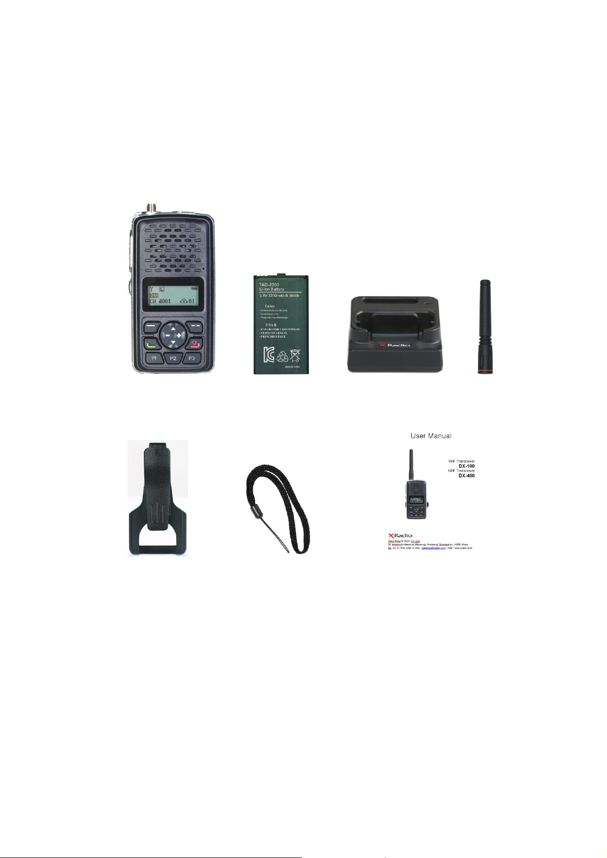
3. Checking items in the package
Components could be changed by buyer request.
Radio unit Battery 2 slot charger Antenna
Belt clip Hand strap User manual
Figure 3-1) DX-100/400 series main items
Battery (XB-2000) : 2200mAH Li-ion battery pack
Page 5
5
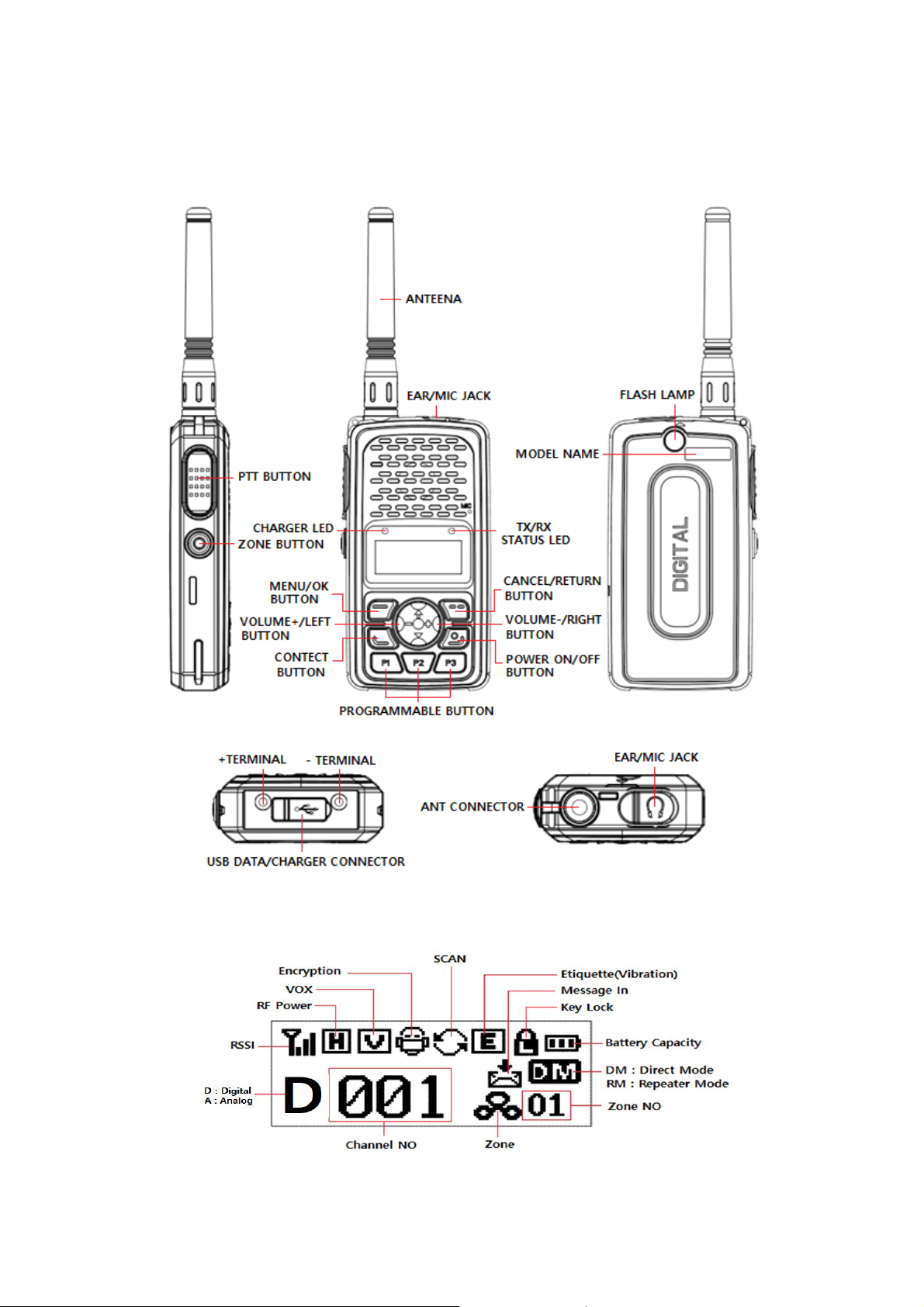
3.1 Appearance of DX-100/400 Series Radio
Figure 3-2) Appearance of DX-100/400 Series Radio
Figure 3-3) LCD Indication of DX-100/400 Series Radio
Page 6
6
4.1 Basic Button Operations
Button & Jack
Operation Description
Power ON/OFF
Press and hold the power button for 2 seconds, the device power is turned ON.
When you press the power button for 2 seconds during use, the power is OFF..
PTT Button
The radio transmits messages when pressing PTT button. It receives messages when
releasing the PTT button.
In order to have clear sound when transmitting, it is recommended to speak around
5~10cm away from the MIC.
Volume/Menu
+/- Button
+/- Button can adjust the call sound by using, and if you press the [+] button,
the sound will be increases if you press the [-] button, the sound will be
smaller. In the menu, you can move to the menu item.
Channel Menu
UP / Down Button
Regularly UP / DOWN buttons are for the channel selection.
In the menu screen, it moves through different functions (UP&DOWN).
Zone Button
When pressing Zone button, zone registered in the program will be selected in order.
You can choose channel by using UP/DOWN button in selected zone.
Menu Button
When pressing the menu button one more time while in the menu, it moves to detailed
menu section of the selected one.
Cancel/Return
Button
Press the button to return to previous item in menu.
In the menu setting screen, it functions as cancel button.
P1, P2, P3
Button
Short press is Programmable Key.
Long Press of button more than 2 seconds is as follows:
P Button
Short Key
Long Key
P1
Programmable
Key Lock ON / OFF(Temporarily)
P2
Programmable
Flash Light ON / OFF
P3
Programmable
Vibration ON / OFF
Contact Button
Press the button to enter the contact list programmed into the radio such as Private,
Group and All Call.
EAR/MIC Jack
This jack is used to connect external speaker Mic, and headset, etc
LED indication
This LED displays the operating status of the device
① TX : Red Lamp. ② RX : Green Lamp.
③ Green blinks: when the frequency is the same but the color code does not match.
④ Low Battery: Red Lamp blinks with “beep” sound
Page 7

7
5. Installation and Removal
When installation of the antenna, giving a strong pressure to the Radio or pulling
the antenna with a strong power from the Radio can make damage on the
antenna connector, which may cause the Radio to have a critical problem.
5.1 Antenna installation and removal
To install the antenna, insert the antenna into antenna connector and screw the antenna
clockwise. To remove the antenna, screw the antenna counter clockwise.
Figure 4-1) Antenna installation and removal
5.2 Battery installation and removal
Removal of the battery is shown in Figure 4-2.
Slide the rear cover in the direction of the top and open the cover. And then remove the
battery. Slide and hold down, the battery is inserted. Insert the back cover to the below hole
and press the cover as shown in Figure 4-3. Then the cover will be equipped.
Figure 4-2) Battery installation and removal Figure 4-3) Rear cover mounting
Page 8

8
5.3 Cradle installation and removal
To install and remove the cradle, push the cradle latch in direction 1 and pull the body in
direction 2, and the installation method is reserved.
Figure 4-4) Cradle(Belt clip) installation and removal
5.4 External accessory connection
Align the body with accessory hole and push and tighten the screws as shown figure 4-5.
To remove the accessory, loosen the screw and pull out.
Figure 4-5) External accessory connection
Page 9

9
5.5 Charging USB
The charging of the enclosed Radio on the other maker’s charger will
cause damage on the battery and also, will cause a trouble on the
Radio.
The continuous rapid discharge (for example, when making a short
circuit on the ‘+’ terminal of battery by a metal substance) may make a
fatal defect and the battery can be exploded. Also, it can cause a fire.
Open the USB cover and connect the micro USB charging adaptor. And the LED will turn
on the red color. When charging is completed, the charging LED will turn green.
Figure 4-6) Charging USB
6. Charging the Battery
6.1 Safety Notes
1) The radio of DX-100/400 series receives power from high-performance Li-ion battery (XB-
2000).
XB-2000 Battery is safe of high performance and highly reliable, and could be charged very fast.
2) Please charge the battery before using the radio for best performance and safety.
3) When you charge the battery that is installed in the Radio, please turn off the radio first to
charge the battery.
Page 10

10
6.2 Charging time
Status
LED indication
Status
LED indication
Charging
Red LED lights
Detecting error
Red LED is flicker
Complete
charging
Green LED lights
Keep charging
Green LED lights
Low battery voltage maybe cause to reduce communication coverage and also make the
performance worse. Please charge the battery in case of following:
1) When you think that the performance of the radio has degradation.
2) The red lamp on RX/TX LED blinks. (every 0.5 second), during transmission or reception.
3) When the battery icon is blinks
4) While the radio is in use, “beep” sounds.
6.3 How to charge
1) Plug the adapter of the XC-300 charger in general power AC220V power outlet.
2) When charging the battery that is equipped with radio, please turn off the power of
the Radio and plug the Radio in the charger.
3) Even if charging is completed (green lamp lights), please charge more for about 30
minutes for a full charge.
Page 11

11
7. Using the DX-100/400 Series
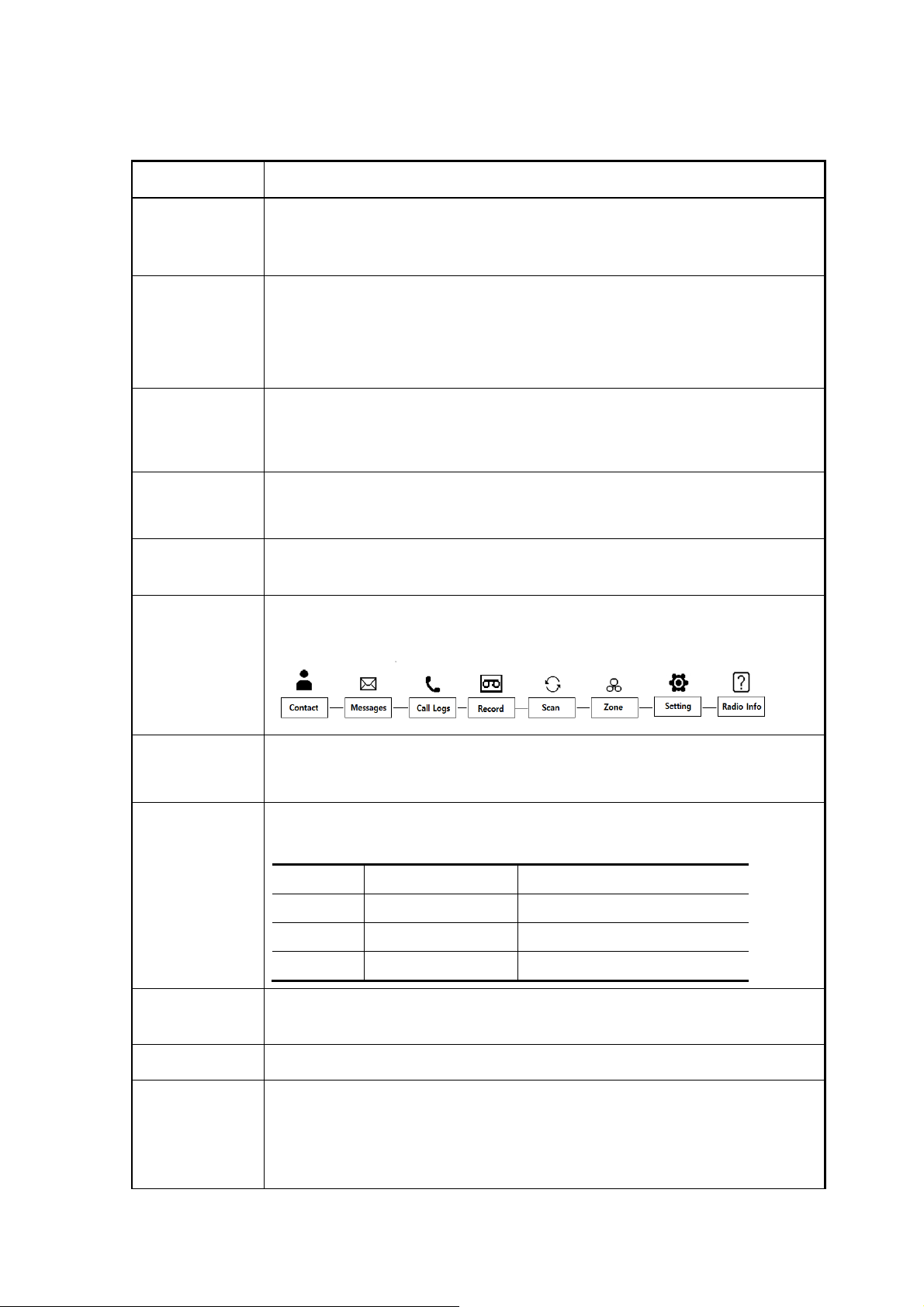
7.1 Menu description
Press the button on the front to enter the menu mode. In the menu mode, there are eight
of the main menus, and set and used according to the application and the environment, it can be
more convenient to use.
Figure 7 DX-100/400 Series Menu Tree
☞ Note) If the menu is not operated for at least 25 seconds after launch, the menu mode is
automatically end and it is switch to receive mode.
7.1.1 Contact List (Digital Mode Only)
The Contact List Provides a list of individuals, groups or all calls of which you can make a
direct call. The lists of contact are set within the radio by the PS. To initiate a call, select the
Contact section from the menu (or press the contact button for direct access_, Press the
menu/enter button to see the list of contact, press the ▲▼ keys to the desired contact and
Page 12

12
press the PTT button to initiate the call. The radio will revert to the original contact/channel
after a preset time as set by the PS. When you enter in the contact menu, the applicable
icon will be shown indicating the type of call.
ICON.
- : Individual Contact List
- : Group Contact List
- : All Contact List (Can be used the terminals with the same channel and color code)
7.1.2 Message (Digital Mode Only)
The message section offers the ability to perform one of the three functions.
Quick Text – The ability to send from a choice of 10 preset messages with up to 40
characters per message. The preset messages are set by the PS.
Inbox - Stores up to 10 received text messages; when the received messages 10, the
oldest message is cleared and the newest incoming message is registered. When a
new message arrives, the contents will be displayed on the LCD When you choose
messages stored in the list, you can view the sent messages and the caller ID that
initiated the call.
Outbox - stores up to 10 outgoing text messages; when the outgoing messages exceed
10, the oldest message is cleared and the newest sent message is registered. When
you choose messages stored in the list, you can view the sent messages and the caller
ID to whom they were sent.
To obtain access, select the Messages section from the menu, press the menu/enter
button to enter into Messages and use the ▲▼ keys to highlight one of the three
choices:
a) Quick Text
Select Quick Text from the message menu by pressing the menu/enter button to view
the registered message(s) using the ▲▼ keys, select the message you want to send,
and press the menu/enter button to see the contents of the message. Press the
menu/enter button again to view the list of contacts, and using the ▲▼ keys, select the
contact for the message to be sent. Press the menu/enter button and the message will
be sent to the contact(s). An acknowledgement will be shown on the display of either
"Sent Success" or "Sent Fail". If the message is failed, check to make sure that the user
receiving the message has their unit powered on.
Page 13

13
b) Inbox
Text messages are shown initially on the screen. If you are in another mode or miss the
message, the message icon will be displayed indicating a new message(s) has arrived.
Select inbox from the message menu by pressing the menu/enter button to view the
registered message(s). Using the ▲▼ keys, select the message you want to view, and
press the menu/enter button to see the contents of the messages. Messages that have
yet to be viewed will be indicated with a downward arrow inside the envelope; after a
message is viewed the arrow will no longer be shown.
If you want to delete messages from the Inbox, select #2 Delete All from within the
Inbox menu by pressing the menu/enter button, the question to Delete All will appear
with the word “Yes?" Press the menu/enter button to delete all messages. If you choose
not to delete the messages, press the return button to exit out.
c) Outbox
Select Outbox from the message menu by pressing the men/enter button to view the
outgoing message(s). Using the ▲▼ keys, select the message you want to view. At this
point, you can resend the message. Press the menu/enter button to view the contents of
the message. Using the ▲▼ keys, select the message you want to send, and press the
menu/enter button to see the contents of the message. Press the menu/enter button
again to view the list of contacts, and using the ▲▼ keys, select the contact for the
message to be sent. Press the menu/enter button and the message will be sent to the
contact(s). An acknowledgement will be shown on the display of either “Sent Success”
or “Sent Fail”. lf the message is failed, check to make sure that the user receiving the
message has their unit powered on.
To delete messages from the outbox, select #2 Delete All from within the Outbox menu
by pressing the menu/enter button, the question to Delete All will appear with the word
“Yes?” Press the menu/enter button to delete all messages. If you choose not to delete
the messages, press the return button to exit out.
☞ Note - When sending and receiving text messages, turn off the power saving mode
7.1.3 Call Logs (Digital Mode Only)
This is the menu to save only individual call log.
Group and All call logs do not save. The message content is managed in the in/outbox
messages.
1) Inbox
It is possible to store up to 10 inbox record and it can see the opponent ID.
Page 14

14
When the inbox is more than 10, the earliest inbox record is cleared first and it is
registered.
If you want to delete inbox record it can be deleted by selecting delete all menu.
2) Outbox
It is possible to store up to 10 outbox record and it can see the opponent ID.
When outbox is more than 10, the earliest outbox record is cleared first and it is
registered.
If you want to delete outbox record it can be deleted by selecting delete all menu.
7.1.4 Call Recording (Digital Mode Only)
This function is used to record the content of outgoing and incoming calls in digital mode
only. There are 3 choices of Settings, Lists, and Delete All. Up to 63
conversations/recordings can be stored with each recording limited to 150 seconds. When
the recordings exceed 63, the oldest message is cleared and the newest incoming message
is registered,
Settings - This section allows the capability to turn the recording capability on off.
Lists – This section allows the viewing of the recorded messages and to play back each
message. To play back a message, use the ▲▼ key to the desired message and press
the menu/enter button to play the recording.
Delete all – This function provides the capability to delete stored recordings. To delete recordings,
select Delete All from within the Voice Recording menu by pressing the menu/enter
button, the question to delete All will appear with the word “Yes” Press the menu/enter
button to delete all messages. If you choose not to delete the messages, press the
return button to exit out.
.
7.1.5 Scan
This function provides the ability to turn scan on/off and review the scan list as programmed
into the radio via the PS. The ability to scan digital and analog channels are available. Contact
your Authorized Dealer for further information.
1) Scan ON/OFF
Select the scan settings or scan release at the scan of menu and go to receive mode..
2) Scan list
Scan list can be set using the CPS program.
Page 15

15
7.1.6 ZONE
Up to 16 zones (with up to 32 channels per zone) can be programmed into the radio via the PS.
To select the desired zone, press the ▲▼ keys and press the menu/enter button to accept the
zone. Contact your Authorized Dealer for further information.
7.1.7 Setting
This is the menu to set various functions of the radio.
This function allows the change to the settings of Power Level, Voice encryption, Voice
Operated Transmit(VOX), Lone Worker, BCL / BLCO, Keypad lock, Tones, Backlight, Brightness,
LED Control, Language, Screen and Power Save.
1. Power Level
This function sets the power transmitting level at high or low. The setting of low power
improves battery life, but diminished talk range.
2. Voice Encryption (Digital Mode Only)
This is a feature to encrypt the incoming and outgoing voice. Voice Encryption function
can be set for each channel from all of the digital channels.
The setting of voice encryption code is using the CPS program, the total number of
encryption can be set from 1 to 10 with AES 128,192,256.
3 VOX
VOX function is transmitted by detecting a voice level without using the PTT button
VOX sensitivity level is 1 - 5 steps, you can set using the CPS program.
4. Lone walker (Digital Mode Only)
It is function to inform others about your safety within the time set in the menu.
Setting time supports up to 1-100 minutes..
5. BCL/BCLO
If the another user on the currently used channel, it is the ability to limit the transmission
so as not to interfere..
BCL: If the current channel is busy, the transmission prohibition
BCLO: The ability to send regardless of the user of the current channel
Page 16

16
6. Keypad Lock
With the exception of the minimum of buttons necessary for the user to prevent
unwanted terminal operation, it is the ability to limit the operation.
When the button lock is on, all buttons are locked except the PTT button, the emergency
button and power ON / OFF button.
When press the key (button lock temporary release key) for 2 seconds, you can use
a button. After 25 seconds from you pressing the last button, to return to the button
again locked.
7. Tones
This function allows the sound of the Radio to be turned ON/OFF. The kind of the tones is
set via the PS. Contact your Authorized Dealer for further information.
8. Backlight
This function allows you to adjust the time for turning on and off the LCD backlight. The
duration of the timed section is set via PS. More information, contact your authorized dealer.
9. Brightness
This function is to adjust the contrast/brightness of the LCD from low to high
10. LED Control
This function is to set the enable or disable the radio status LED. The LED status can be
set via the PS.
11. Language
The feature is to select the language for the menus.
12. Screen
The feature allows the ability to change between Screen 1, Screen 3 for Numeric or Screen
2 for Alphanumeric. The Information displayed is set via user selected.
13. Power Saving Mode
This function allows the radio to enter a power saving mode to extend battery usage time.
Off is full power, 1/1 is 50% on / 50% off; 1/2 is 33 % on/67% off; 1/4 is 25 % on/75% off.
Note : When sending and receiving text messages, turn off the power saving mode
Page 17

17
7.1.8 Radio Information
Don’t remove the antenna from the Radio or don’t transform the antenna or don’t make
any change on the antenna. The strong electronic wave to be emitted from the Radio
can have an effect on the performance of the Radio and can cause the Radio to have a
defect.
Don’t use the accessories (such as rechargeable battery, adaptor, external speaker
microphone and earphone, etc.) from the other makers, which can cause to make a
defect on battery and a malfunction or a defect on the Radio.
Don’t disassemble or reorganize the Radio. The disassembly or reorganization will be
causes of defect or malfunction and it will be impossible to make repair afterward.
Also, a punishment can be made by law.
Don’t use the other frequency except for the permitted frequency in order not to be
punished by law.
• Don’t give an excessive shock to the Radio.
• Don’t place the Radio where the direct sunlight and/or the high temperature occurs.
• If the Radio is placed for a long time in car in summer, the hot temperature in the car
may cause an explosion of battery.
• Don’t make a damage to the battery by a sharp substance and/or an excessive shock.
A menu that shows the information in this device..
8. Precautions
8.1 Matters affecting the performance of the equipment.
Page 18

18
9.2 Influences to the operations of Radio or other Equipments.
Please turn off the Radio before boarding on airplane.
When you want to use the Radio in the airplane, please follow the rules in the airplane
or the instructions by crew.
In case of the area that medical equipments are being used, please use the Radio after
discussion with the equipment maker or the related doctor.
Please don’t use the Radio at the place where computer or the other electric/electronic
devices are being used, because the strong electronic wave from the Radio can have an
effect on the equipments.
• Please keep the Radio away at least 1inch from the body.
• If the outside surface of antenna gets stripped out, it can make a burn on the skin.
• If you contact a conductive metal to battery terminal, a heat can be made and it may
cause fire, explosion and burn. Especially, please be careful when putting the battery
in a pocket or a bag.
• When using an earphone, please don’t listen to the sound at a high level. The high
sound may have a bad effect on your ear.
• After setting the volume of the Radio at a low level, please adjust the volume step by
step to the level you want. A sudden high sound may give a bad damage to the ear or
the heart.
• Please don’t remove or replace or charge or discharge the battery at a dangerous area,
since it may cause an explosion or a fire by an electrical spark.
• At the area where an electromagnetic force can be made, please make sure to turn off
the power of the Radio.
The Radio emits a strong electronic wave, which may have an effect on the operation of other equipments
and also, can be influenced by the other devices.
10. Safety Notes
Please make sure to read the followings for safe and effective use of the Radio.
Page 19

19
Warranty Card
Thank you for purchasing DX-100D/400D Series.
1. This product has passed strict quality control and testing process.
2. Warranty is one year from the day the factory.
• Failure of the product under normal operating conditions, during the warranty period
may be repaired by YeonHwa M Tech Co.,Ltd or our authorized service organization
free of charge.
3. For the following cases, some service fees will be charged.
• It occurs after the warranty period has passed, performance failure, malfunction or
damage.
• When the product is damaged due to user’s mishandling, abuse or
improper operation.
• When the product is damaged due to user’s modification, attempted repair
or otherwise access to sealed/non-user serviceable items.
• When the product is damaged due to fires, pollution, earthquakes and any other natual
or unnatural conditions, accidents, etc.
4. Product check list
Model No.
DX-100D/400D Series
Serial No.
Purchase date
Purchaser
Name
Address
※ When you purchasing, please fill out this check list.
YeonHwa M Tech Co.,Ltd
36 Jeonpa-Ro, 44Beon-Gil, Manan-Gu, Anyang-City, Gyeongg-Do, Korea
Tel : 031)444-7270, 070-4827-3200
FAX : 031)444-7271
Page 20

Cautions
1 The device complies with RF specifications when it is used at 25mm distance from your body.
2 Risk of explosion if battery is replaced by an incorrect type, dispose of used batteries
according to the instructions.
3 Adapter shall be installed near the equipment and shall be easily accessible.
4 EUT Temperature:-10℃~+40℃, The charging temperature of battery is - 5℃~+50℃,do not
charging when temperature is below -5℃.
5 Adapter information:
Model name: RT-TA520EW
Input: AC 100 ~ 240V 50/60Hz 0.35A
Output: DC 5.0V,2.0A
Hereby, YeonHwa M Tech Co.,Ltd.
Declares that this Digital 3W Portable Radio is in compliance with the essential requirements
and other relevant provisions of directive 2014/53/EU and without limitation of use in Europe .
The declaration of conformity may be consult at:
Manufacturer:
YeonHwa M Tech Co.,Ltd.
36, Jeonpa-ro 44beon-gil, Manan-gu, Anyang-si, Gyeonggi-do 14086
Korea
Page 21

Cautions
1 The device complies with RF specifications when it is used at 25mm distance from your body.
2 Risk of explosion if battery is replaced by an incorrect type, dispose of used batteries
according to the instructions.
3 Adapter shall be installed near the equipment and shall be easily accessible.
4 EUT Temperature:-10℃~+40℃, The charging temperature of battery is -5℃~+55℃,do not
charging when temperature is below -5℃.
5 Adapter information:
Model name: RT-TA520EW
Input: AC 100 ~ 240V 50/60Hz 0.35A
Output: DC 5.0V,2.0A
Hereby, YeonHwa M Tech Co.,Ltd.
Declares that this Digital 3W Portable Radio is in compliance with the essential requirements
and other relevant provisions of directive 2014/53/EU and without limitation of use in Europe .
The declaration of conformity may be consult at:
Manufacturer:
YeonHwa M Tech Co.,Ltd.
36, Jeonpa-ro 44beon-gil, Manan-gu, Anyang-si, Gyeonggi-do 14086
Korea
Page 22

SAR statement (DX-400)
The max head SAR is 1.029 W/Kg and The max body SAR is 2.210 W/Kg which compliance
with Specific Absorption Rate (SAR) for Occupational/controlled exposure (Localized 10-gram
SAR for head and trunk, limit: 10.0W/kg) specified in Council Recommendation 1999/519/EC
SAR statement (DX-100)
The max head SAR is 0.497 W/Kg and The max body SAR is 0.491 W/Kg which compliance
with Specific Absorption Rate (SAR) for Occupational/controlled exposure (Localized 10-gram
SAR for head and trunk, limit: 10.0W/kg) specified in Council Recommendation 1999/519/EC
Page 23

FCC statement
This device complies with Part 15 of the FCC Rules. Operation is subject to the following two
conditions: (1)this device may not cause harmful interference, and (2) this device must accept
any interference received, including interference that may cause undesired operation.
Changes or modifications not expressly approved by the party responsible for compliance could
void the user's authority to operate the equipment.
NOTE: This equipment has been tested and found to comply with the limits for a
Class B digital device, pursuant to Part 15 of the FCC Rules. These limits are
designed to provide reasonable protection against harmful interference in a
residential installation. This equipment generates, uses and can radiate radio
frequency energy and, if not installed and used in accordance with the
instructions, may cause harmful interference to radio communications. However,
there is no guarantee that interference will not occur in a particular installation.
If this equipment does cause harmful interference to radio or television reception,
which can be determined by turning the equipment off and on, the user is
encouraged to try to correct the interference by one or more of the following
measures:
-- Reorient or relocate the receiving antenna.
-- Increase the separation between the equipment and receiver.
-- Connect the equipment into an outlet on a circuit different
from that to which the receiver is connected.
-- Consult the dealer or an experienced radio/TV technician for help.
This device and its antenna(s) must not be co-located or operation in conjunction with any other
antenna or transmitter.
Hold the transmitter approximately 2 inches (25mm) from your face and speak in a normal voice,
with the antenna pointed up and away.
Page 24

RF Energy Exposure Awareness and Control Information and Operational Instructions for
Occupational Use
Notice: this radio is intended for use in occupational/controlled conditions where users have full
knowledge of their exposure and can exercise control over their exposure to meet the
occupational limits in FCC and International standards. This radio device is NOT authorized for
general population consumer use.
Federal Communication Commission (FCC) Regulations
When Digital 3W Portable Radio is used as a consequence of employment, the FCC requires users
to be fully aware of and able to control their exposure to meet occupational requirement.
Exposure awareness can be facilitated by the use of a product label directing users to specific
user awareness information. Your Digital 3W Portable Radio has a RF Exposure Product Label.
Also, your Digital 3W Portable Radio Radio user manual includes information and operating
instructions required to control your RF exposure and satisfy compliance requirements.
Compliance with RF Exposure Standards
Your Digital 3W Portable Radio is designed and tested to compliance with a number of national
and international standards and guidelines for human exposure to radio frequency
electromagnetic energy. This radio compliance with the IEEE (FCC) and ICNIRP exposure limits for
occupational/controlled RF exposure environments at operating duty factors of up to 50% talk –
50% listen and is approved for occupational use only. In terms of measuring RF energy for
compliance with these exposure guidelines, your radio generates measureable RF energy only
while it is transmitting (during talking), not when it is receiving (listening) or in standby mode.
Your Digital 3W Portable Radio complies with the following RF energy exposure standards and
guidelines:
● United States Federal Communications Commission (FCC), Code of Federal Regulations;
● Institute of Electrical and Electronic Engineers (IEEE) C95.1
● International Commission on Non-lionizing Radiation Protection (ICNIRP)
RF Exposure Compliance and Control Guidelines and Operating Instructions for Two-Way Radio
Operations
To control your exposure and ensure compliance with the occupational/controlled environment
exposure limits, always adhere to the following procedures;
● DO NOT remove the RF Exposure Label from the device
● User awareness instructions should accompany device when transferred to other users.
Operational Instructions and Training Guidelines
To ensure optimal performance and compliance with the occupational/controlled environment
RF energy exposure limits in the above standards and guidelines, users should transmit no more
than 50% of the time and always adhere to the following procedures;
● In front of the face, hold the radio in a vertical position with microphone (and other parts of
the radio including the antenna) at least one inch (2.5 centimeters) away from the nose or
lips. Keep the radio at a proper distance is important to ensure compliance.
Page 25

Note: RF exposure decrease with increasing distance from the antenna.
● Body Worn Operation; when worn the body, always place the radio in an approved clip,
holder, or body harness for this product.
Using approved body-worn accessories is important because the use of non-approved
accessories may results in exposure levels, which exceed the occupational/controlled
environment RF exposure limits
Using only approved supplied or replacement antennas, batteries, and audio accessories, use
of non-approved antennas, batteries, and wired or wireless accessories may exceed the
applicable RF exposure guidelines (IEEE, ICNIRP or FCC).
Page 26

ISED statement
English Statement
This device contains licence-exempt transmitter(s)/receiver(s) that comply with Innovation,
Science and Economic Development Canada’s licence-exempt RSS(s). Operation is subject to the
following two conditions: 1, This device may not cause interference. 2, This device must
accept any interference, including interference that may cause undesired operation of the device.
Safety Information
This equipment complies with IC radiation exposure limits set forth for an controlled
exposure environment. When the talk bottom is pushed, it sends out radio frequency (RF)
signals. The devices is authorized to operate at a duty not to exceed 50%.
For body-worn operation, this radio has been tested and meets the IC RF exposure guidelines when
used with manufacturer accessories supplied or designated for this product. Use of
other accessories may not ensure compliance with FCC RF exposure guidelines. Use only the
supplied antenna. Unauthorized antennas, modifications, or attachments could damage the
transmitter and may violate FCC regulations.
Hold the transmitter approximately 2 inches (25mm) from your face and speak in a normal voice,
with the antenna pointed up and away.
Canada Dé claration
Le pré sent appareil est conforme aux CNR d'Industrie Canada applicables aux appareils radio
exempts de licence. L'exploitation est autorisé e aux deux conditions suivantes : (1) l'appareil ne
doit pas produire de brouillage, et (2) l'utilisateur de l'appareil doit accepter tout brouillage radioé
lectrique subi, mê me si le brouillage est susceptible d'en compromettre le fonctionnement.”
l'information sur la sécurité ce maté riel est conforme aux limites de dose d'exposition aux
rayonnements é noncé s pour contrô lé es l'exposition environnement.quand le parler bas est
poussé , il envoie des signaux radio fré quence (RF). les dispositifs est autorisé e à exploiter, à une
obligation de ne pas dé passer 50%. opé ration porté s sur le corps, la radio a é té testé et respecte
les directives d'exposition aux IC RF utilisé e avec le fabricant d'accessoires fournis ou dé signé s
pour ce produit. utilisation d'autres accessoires ne peut s'assurer de la conformité avec
les lignes directrices sur l'exposition aux radiofré quences. utiliser uniquement la fournies antenne.
les modifications ou les antennes de non autorisé e, pourrait nuire à l'é metteur et peuvent violer
les rè glements de la IC.
l'é metteur à environ 2 inches (25 mm) de votre visage et parlez normalement, avec l'antenne a
signalé etloin.
Page 27

RF Energy Exposure Awareness and Control Information and Operational Instructions for
Occupational Use
Informations sur la sensibilisation et le contrôle de l'exposition à l'énergie RF et instructions de
mise en service en vue de l'utilisation professionnelle
Notice: this radio is intended for use in occupational/controlled conditions where users have full
knowledge of their exposure and can exercise control over their exposure to meet the
occupational limits in ISED and International standards. This radio device is NOT authorized for
general population consumer use.
Avis: cette radio est destinée à être utilisée dans des conditions professionnelles / contrôlées où
les utilisateurs ont une connaissance complète de leur exposition et peuvent contrôler leur
exposition afin de respecter les limites professionnelles définies par la ISED et les normes
internationales. Cet appareil radio N'EST PAS autorisé pour un usage grand public.
Innovation, Science and Economic Development Canada (ISED) Regulations
When Digital 3W Portable Radio is used as a consequence of employment, the ISED requires
users to be fully aware of and able to control their exposure to meet occupational requirement.
Exposure awareness can be facilitated by the use of a product label directing users to specific
user awareness information. Your Digital 3W Portable Radio has a RF Exposure Product Label.
Also, your Digital 3W Portable Radio user manual includes information and operating instructions
required to control your RF exposure and satisfy compliance requirements.
Règlement sur l'innovation, les sciences et le développement économique Canada (ISDE)
Lorsque la radio portative numérique 3W est utilisée à la suite d'un emploi, la ISED exige que les
utilisateurs soient pleinement conscients de leur exposition et en mesure de contrôler leur
exposition pour répondre aux exigences professionnelles. La sensibilisation à l'exposition peut
être facilitée par l'utilisation d'une étiquette de produit orientant les utilisateurs vers des
informations de sensibilisation spécifiques. Votre radio portative Digital 3W a une étiquette de
produit d’exposition aux RF. De plus, le manuel d'utilisation de votre radio portative Digital 3W
comprend les informations et les instructions d'utilisation nécessaires pour contrôler votre
exposition aux RF et satisfaire aux exigences de conformité.
Compliance with RF Exposure Standards
Your Digital 3W Portable Radio is designed and tested to compliance with a number of national
and international standards and guidelines for human exposure to radio frequency
electromagnetic energy. This radio compliance with the IEEE (ISED) and ICNIRP exposure limits for
occupational/controlled RF exposure environments at operating duty factors of up to 50% talk –
50% listen and is approved for occupational use only. In terms of measuring RF energy for
compliance with these exposure guidelines, your radio generates measureable RF energy only
while it is transmitting (during talking), not when it is receiving (listening) or in standby mode.
Your Digital 3W Portable Radio complies with the following RF energy exposure standards and
guidelines:
Innovation, Science and Economic Development Canada (ISED), Code of Canada Regulations;
Page 28

Institute of Electrical and Electronic Engineers (IEEE) C95.1
International Commission on Non-lionizing Radiation Protection (ICNIRP)
Conformité aux normes d'exposition aux RFVotre radio portative numérique
Votre radio portative numérique 3W est conçue et testée pour être conforme à un certain
nombre de normes et directives nationales et internationales relatives à l'exposition des
personnes à l'énergie électromagnétique par radiofréquences. Cette radio respecte les limites
d'exposition IEEE (ISED) et ICNIRP pour les environnements d'exposition professionnels /
contrôlés aux fréquences de service pouvant atteindre 50% de conversation - 50% d'écoute et est
approuvé pour une utilisation professionnelle uniquement. Pour ce qui est de mesurer l’énergie
RF afin de respecter ces consignes d’exposition, votre radio ne génère une énergie RF mesurable
qu’en cours de transmission (en conversation), pas en réception (écoute) ou en mode veille.Votre
radio portative Digital 3W est conforme aux normes et directives relatives à l'exposition aux
énergies RF suivantes:Innovation, Sciences et Développement économique Canada (ISDE),
Règlement sur le Code du Canada;Institut des ingénieurs électriciens et électroniciens (IEEE)
C95.1Commission internationale de protection contre les radiations non ionisantes (ICNIRP)
RF Exposure Compliance and Control Guidelines and Operating Instructions for Two-Way Radio
Operations
To control your exposure and ensure compliance with the occupational/controlled environment
exposure limits, always adhere to the following procedures;
DO NOT remove the RF Exposure Label from the device
User awareness instructions should accompany device when transferred to other users.
Directives de conformité et de contrôle de l'exposition aux RF et instructions d'utilisation
pour les opérations radio bidirectionnellesPour
contrôler votre exposition et garantir le respect des limites d'exposition professionnelle / en
environnement contrôlé, respectez toujours les procédures suivantes.NE PAS retirer
l’étiquette d’exposition aux RF de l’appareilLes instructions de sensibilisation des utilisateurs
doivent accompagner l'appareil lors de son transfert à d'autres utilisateurs.
Operational Instructions and Training Guidelines
To ensure optimal performance and compliance with the occupational/controlled environment
RF energy exposure limits in the above standards and guidelines, users should transmit no more
than 50% of the time and always adhere to the following procedures;
In front of the face, hold the radio in a vertical position with microphone (and other parts of
the radio including the antenna) at least one inch (2.5 centimeters) away from the nose or
lips. Keep the radio at a proper distance is important to ensure compliance.
Note: RF exposure decrease with increasing distance from the antenna.
Body Worn Operation; when worn the body, always place the radio in an approved clip,
holder, or body harness for this product.
Using approved body-worn accessories is important because the use of non-approved
accessories may results in exposure levels, which exceed the occupational/controlled
environment RF exposure limits
Page 29

Using only approved supplied or replacement antennas, batteries, and audio accessories, use
of non-approved antennas, batteries, and wired or wireless accessories may exceed the
applicable RF exposure guidelines (IEEE, ICNIRP or ISED).
Instructions opérationnelles et directives de formation
Pour garantir des performances optimales et le respect des limites d'exposition aux énergies
RF définies dans les normes et directives susmentionnées, les utilisateurs ne doivent pas
transmettre plus de 50% du temps et se conformer systématiquement aux procédures
suivantes.En face du visage, tenez la radio en position verticale avec le microphone (et les
autres éléments de la radio, y compris l’antenne) à au moins 2,5 cm du nez ou des lèvres.
Maintenir la radio à une distance appropriée est important pour assurer la
conformité.Remarque: l'exposition aux RF diminue avec l'augmentation de la distance par
rapport à l'antenne.Opération portée sur le corps; Lorsque vous portez la carrosserie, placez
toujours la radio dans un clip, un support ou un harnais approuv é pour ce
produit.L'utilisation d'accessoires approuvés pour le port du corps est importante car
l'utilisation d'accessoires non approuvés peut entraîner des niveaux d'exposition supérieurs
aux limites d'exposition RF des environnements professionnels / contrôlés.Si vous utilisez
uniquement des antennes, des batteries et des accessoires audio approuvés ou de
remplacement fournis, l'utilisation d'antennes, de batteries et d'accessoires câblés ou sans fil
non approuvés peut dépasser les consignes d'exposition RF applicables (IEEE, ICNIRP ou
ISED).Instructions opérationnelles et directives de formation
 Loading...