

Page 1
Manual 4.0
VIPdigital Manual 4.0 Yellowtec 2004 Rev. 26.07.2004 Page 1
Page 2

TABLE OF CONTENTS
1 BRIEF DESCRIPTION......................................................................................... 6
2 PRIOR TO BEGINNING...................................................................................... 7
2.1 CONVENTIONS USED IN THE MANUAL..................................................................... 7
2.1.1 Using the screen.................................................................................................................... 7
2.1.2 Printout .................................................................................................................................. 7
2.2 UNPACKING........................................................................................................ 8
2.3 SCOPE OF DELIVERY ........................................................................................... 8
2.4 SAFETY INSTRUCTIONS........................................................................................ 9
3 GETTING STARTED WITH VIPDIGITAL.......................................................... 10
3.1 ELECTRICAL CONNECTION.................................................................................. 10
3.2 ACTIVATION...................................................................................................... 10
3.3 USING INTERNAL PRESETS ................................................................................. 10
3.4 USING SMARTCARD .......................................................................................... 10
3.5 THE ENTER BUTTON.......................................................................................... 11
3.6 FIRST AUDIO CONNECTIONS ............................................................................... 11
4 UNIT DESCRIPTION......................................................................................... 12
4.1 FRONT PANEL................................................................................................... 12
4.1.1 Remote Control RJ12 (1) ....................................................................................................12
4.1.2 Level Indicators (2).............................................................................................................. 12
4.1.3 Function Display (3) ............................................................................................................13
4.1.4 Preset Recall (4)..................................................................................................................13
4.1.5 Enter (5)............................................................................................................................... 14
4.1.6 Selector (6).......................................................................................................................... 14
4.1.7 Card Slot (7) ........................................................................................................................ 14
4.2 THE ENTER MODE ............................................................................................ 15
4.2.1 Assign Preset ...................................................................................................................... 15
4.2.2 Meter Mode ......................................................................................................................... 15
4.2.3 State .................................................................................................................................... 16
4.2.4 Contrast............................................................................................................................... 16
4.2.5 Escape................................................................................................................................. 16
4.3 BACK PANEL..................................................................................................... 17
4.3.1 Power supply....................................................................................................................... 17
4.3.2 Audio connections............................................................................................................... 17
4.3.2.1 Analog In 1 and 2....................................................................................................................... 17
VIPdigital Manual 4.0 Yellowtec 2004 Rev. 26.07.2004 Page 2
Page 3

4.3.2.2 Analog Left Out and Right Out................................................................................................... 18
4.3.2.3 Analog Hybrid-Out ..................................................................................................................... 18
4.3.2.4 Digital AES/EBU-Sync/In........................................................................................................... 18
4.3.2.5 Digital AES/EBU-Out................................................................................................................. 18
4.3.3 Remote Control ................................................................................................................... 19
4.3.3.1 Remote Control D-Sub .............................................................................................................. 19
4.3.3.2 Control-Out/In............................................................................................................................ 19
4.3.3.3 Technical data Control-Out/In (GPO/GPI) ................................................................................. 19
5 SOFTWARE INSTALLATION........................................................................... 20
5.1 INSTALLATION FROM THE CD-ROM.................................................................... 20
5.2 INSTALLATION FROM A ZIP-FILE.......................................................................... 20
5.3 INFO: THE MAIN SOFTWARE COMPONENTS OF VIPDIGITAL .................................... 20
6 CONNECT VIPDIGITAL TO THE COMPUTER ................................................ 21
6.1 INSTALLING THE CONNECTION ............................................................................ 21
6.2 STANDARD APPLICATION START-UP PROCEDURE................................................ 21
6.3 TROUBLESHOOTING .......................................................................................... 22
6.4 ASSIGNING COM PORTS................................................................................... 23
6.5 CONNECTING SEVERAL VIPDIGITAL TO YOUR PC................................................. 23
7 VIPCON - THE CONFIGURATION SOFTWARE.............................................. 24
7.1 START AND END OF PROGRAM............................................................................ 24
7.2 PASSWORD PROTECTION................................................................................... 24
7.3 ONLINE OPERATION........................................................................................... 25
7.4 OFFLINE OPERATION ......................................................................................... 25
7.5 MENU: FILE ...................................................................................................... 26
7.5.1 Sub-menu: New................................................................................................................... 26
7.5.2 Sub-menu: Open................................................................................................................. 26
7.5.3 Sub-menu: Save.................................................................................................................. 26
7.5.4 Sub-menu: Save as............................................................................................................. 26
7.5.5 Sub-menu: Change Password ............................................................................................ 27
7.5.6 Sub-menu: Exit.................................................................................................................... 27
7.6 MENU: UNIT ..................................................................................................... 28
7.6.1 Sub-menu: Save to Unit ...................................................................................................... 28
7.6.2 Sub-menu: Load from Unit .................................................................................................. 28
7.7 MENU: FIRMWARE UPDATE................................................................................ 29
7.8 MENU: HELP..................................................................................................... 30
7.8.1 Sub-menu: Help F1 ............................................................................................................ 30
7.8.2 Sub-menu: About................................................................................................................. 30
VIPdigital Manual 4.0 Yellowtec 2004 Rev. 26.07.2004 Page 3
Page 4

7.9 WINDOW: GENERAL OPTIONS ............................................................................ 31
7.9.1 Range: Synchronization ...................................................................................................... 31
7.9.1.1 Field: Frequency........................................................................................................................ 31
7.9.1.2 Field: Sync Source..................................................................................................................... 31
7.9.2 Range: Access Internal Preset............................................................................................ 32
7.9.3 Range: Preset Order ........................................................................................................... 32
7.9.4 Range: Replace Internal Preset.......................................................................................... 32
7.9.5 Range: Read SmartCard..................................................................................................... 33
7.9.6 Range: Write SmartCard..................................................................................................... 33
7.9.7 Range: Meter Default .......................................................................................................... 33
7.9.8 Range: Enter Button............................................................................................................ 33
7.9.9 Range: Input Levels ............................................................................................................34
7.9.10 Range: Output Levels...................................................................................................... 34
7.10 WINDOW: CONTROL LOGIC ........................................................................... 35
7.10.1 Range: Trigger Outputs................................................................................................... 35
7.10.1.1 Trigger Output Functions........................................................................................................... 36
7.10.1.2 Trigger Output Actions............................................................................................................... 36
7.10.2 Range: Pulse Duration..................................................................................................... 36
7.10.3 Range: Trigger Inputs...................................................................................................... 37
7.10.3.1 Trigger Input Actions.................................................................................................................. 37
8 VIPREMOTE - THE REMOTE SOFTWARE...................................................... 38
8.1 GENERAL ......................................................................................................... 38
8.1.1 Start and end of program ....................................................................................................39
8.1.2 Offline mode ........................................................................................................................ 39
8.1.3 Online mode........................................................................................................................ 39
8.1.4 Start-Up Mode ..................................................................................................................... 40
8.1.5 Help call............................................................................................................................... 41
8.1.6 Info window.......................................................................................................................... 41
8.1.7 Exit VIPremote..................................................................................................................... 41
8.2 AUDIO PROCESSING MODULE ............................................................................ 42
8.2.1 Basic information................................................................................................................. 42
8.2.2 Module: Input....................................................................................................................... 43
8.2.2.1 Input source............................................................................................................................... 43
8.2.2.2 Input Gain.................................................................................................................................. 43
8.2.2.3 Phantom Power......................................................................................................................... 44
8.2.3 Module: Subsonic................................................................................................................ 44
8.2.4 Module: Phase..................................................................................................................... 44
8.2.5 Module: De-esser................................................................................................................45
8.2.6 Module: Equalizer................................................................................................................ 46
8.2.7 Module: Expander ............................................................................................................... 47
8.2.8 Module: AGC....................................................................................................................... 48
8.2.9 Module: Compressor........................................................................................................... 49
8.2.10 Module: Delay.................................................................................................................. 50
8.2.11 Module: Reverb ............................................................................................................... 51
8.2.12 Module: Limiter ................................................................................................................ 52
8.3 PRESET MANAGEMENT ...................................................................................... 53
8.3.1 Overview.............................................................................................................................. 53
8.3.2 Setting presets..................................................................................................................... 54
8.3.2.1 Renaming presets...................................................................................................................... 54
8.3.2.2 Copying parameters between presets ....................................................................................... 54
VIPdigital Manual 4.0 Yellowtec 2004 Rev. 26.07.2004 Page 4
Page 5

8.3.3 Saving and loading presets................................................................................................. 55
8.3.3.1 Saving to PC.............................................................................................................................. 55
8.3.3.2 Loading from the PC.................................................................................................................. 56
8.3.3.3 Saving to VIPdigital.................................................................................................................... 57
8.3.3.4 Saving to SmartCard ................................................................................................................. 57
8.3.3.5 Loading from VIPdigital.............................................................................................................. 58
8.3.4 Setting SmartCard presets.................................................................................................. 58
9 TECHNICAL DRAWINGS/DESCRIPTIONS ..................................................... 59
9.1 TECHNICAL DATA.............................................................................................. 59
9.2 BLOCK DIAGRAM ............................................................................................... 60
9.3 PIN OUT TABLE................................................................................................. 61
9.4 GPI/GPO CIRCUIT EXAMPLES............................................................................ 62
10 UPDATING VIPDIGITAL TO 4.0.................................................................... 63
10.1 PRIOR TO BEGINNING.................................................................................... 63
10.2 INSTALLING THE NEW SOFTWARE ................................................................... 63
10.3 CONNECT VIPDIGITAL TO THE COMPUTER...................................................... 63
10.4 PERFORMING THE FIRMWARE UPDATE ........................................................... 63
10.5 UPDATING PRESET FILES.............................................................................. 65
10.6 UPDATING SMARTCARDS.............................................................................. 65
10.7 COMPATIBILITY ............................................................................................ 66
10.7.1 Configuration files............................................................................................................ 66
10.7.2 Preset files....................................................................................................................... 66
10.8 CHECKING VERSION NUMBERS....................................................................... 66
11 TROUBLESHOOTING................................................................................... 67
12 MISCELLANEOUS ........................................................................................ 68
12.1 WARRANTY.................................................................................................. 68
12.2 CE CONFORMITY DECLARATION..................................................................... 69
VIPdigital Manual 4.0 Yellowtec 2004 Rev. 26.07.2004 Page 5
Page 6
1 BRIEF DESCRIPTION
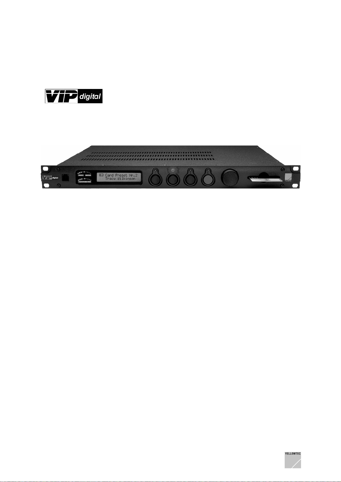
VIPdigital
Its advanced Sharc DSP technology and its algorithms especially optimized for speech give you more
power than any other mic processor you’ve encountered. It lets you tailor your talent’s voice with an
unprecedented arsenal of processing tools, then mates it perfectly with your station’s on-air audio
processing.
Reference class microphone amplifier, subsonic filter, phase rotator, de-esser, 4-band parametric EQ,
expander, AGC, compressor, limiter, reverb and delay -
VIPdigital
Set all audio parameters conveniently in the VIPremote Windows software (included in the scope of
delivery) and save these as audio presets to a SmartCard or in the non-volatile memory of your
VIPdigital.
From the control room to the newsroom – from the
recording studio to the editing desk – each speaker
has always his personal VIPdigital presets with him
and may use his/her settings on each working
place equipped with VIPdigital by simply inserting
the SmartCard.
SmartCard stops the nonsense of using a more or
less suitable setting for everyone. Each
combination of voice, microphone and studio
environment requires individual settings to achieve
an optimum result.
is a powerful digital voice processor.
offers all these tools in a compact 19“ format on only 1 HU.
Connect VIPdigital to your PC. VIPremote will then function like a “remote control” for your VIPdigital.
You will have a differentiated and convenient access to all audio editing parameters. The settings
made here will be transmitted immediately, i.e. can be heard at once.
A set of 100 presets can be saved as Internal Presets to your VIPdigital. They are available without
any PC. Reload them to your PC for further modification at any time.
Store up to 3 presets as individual settings for one speaker to the SmartCard.
For convenient backup on your PC, choose from 3 different file formats: Single Preset file, SmartCard
Preset file (3 presets and holder name) or Internal Preset file (100 presets).
Create as many preset files as you need. If required, you may take the factory settings as a starting
point for your settings.
Also, use the Windows software, VIPcon, included in the scope of delivery, to define basic system
configurations for your VIPdigital. Among other things, you may define the control inputs and the
control outputs here for a perfect integration of VIPdigital into your studio environment. VIPcon
provides a password protection and thus allows the rejection of access rights.
VIPdigital is the name for a most sophisticated, yet practical approach.
Other features in a few keywords:
- The analog input prvides 2 switchable input connectors. Connect different microphones or one
microphone and one headset. The respective source selection is stored in the preset and will
be performed when the SmartCard is inserted or a preset is selected
- Multiple analog and digital outputs
- Additional direct analog output (post input stage, e.g. selection for telephone hybrid)
- Digital AES/EBU input with SRC, also suitable for a synchronization with the house clock
- Latency less than 1.5 ms (and is thus included in the best of its class)
VIPdigital Manual 4.0 Yellowtec 2004 Rev. 26.07.2004 Page 6
Page 7

2 PRIOR TO BEGINNING
2.1 Conventions used in the manual
2.1.1 Using the screen
This manual was prepared, using Adobe Acrobat.
To be able to use this manual, you must have Acrobat Reader 5.x or higher installed on your
computer. Acrobat Reader is contained on the supplied CD-ROM. Follow the installation instructions
from Adobe to install the Acrobat Reader. If you are not familiar with the use of Acrobat reader, use
the integrated Adobe Online Help.
We recommend the screen use of this manual. The file name is:
VIPd_manual.pdf
Double click on the file symbol on your Windows PC to open the manual.
Note:
You may open this manual from the VIPdigital programs VIPcon and VIPremote by a help call
(HELP), provided the VIPd_manual.pdf file exists in the installation and/or program folder. This will be
the case after an execution of the normal installation routine.
Activate the navigation window and the bookmark view in Acrobat Reader.
The left screen margin shows the table of contents and provides an overview of the entire document.
Clicking on the plus (+) and/or minus (-) character allows you to decide how many sub-ordinated
headline levels are to be displayed.
Using a mouse click on the headline directly calls the appropriate text. The part of the table of contents
associated with the text which can just be viewed on the screen is highlighted. Thus, you may safely
navigate through the document.
Furthermore, the text contains numerous links. A link appears in blue color and is underscored.
Moving the mouse pointer over a link changes the pointer signal to a pointing hand (hand with an
extended forefinger). Now, click on the link to directly call the part of the text and/or the headline to
which the link refers to.
For quick navigation, Acrobat Reader provides convenient tools for paging, jumping
backwards/forwards, toggling between the different view options etc.
Some links refer to our website (
you may establish an Internet connection to our website by clicking on one of these links.
www.yellowtec.com). If your PC system is equipped appropriately,
2.1.2 Printout
If you prefer working with paper to working with the screen, you may print out the PDF manual. The
page layout is designed for the DIN A4 paper format. The detailed table of contents appears at the
start of the printout so that you are safely guided through the document even in the hardcopy version.
If a printout is not made in colour, the links can be identified only by their underscores. Except for
links, underscores are normally only used for special information such as Note: and/or Important: so
that the links can also be identified in a black/white printout.
VIPdigital Manual 4.0 Yellowtec 2004 Rev. 26.07.2004 Page 7
Page 8

2.2 Unpacking
VIPdigital is delivered in a carton. Unpack the carton carefully. Remember the environment and
dispose of the parts of foamed material and the cartons separately.
2.3 Scope of delivery
The VIPdigital scope of delivery includes:
1. VIPdigital, 19“/1HU unit
2. Serial interconnecting cable to the computer (RS232)
3. Mains cable (not
4. YELLOWTEC CD-ROM with software and documentation
5. YELLOWTEC SmartCard
6. “Getting Started“ brochure
Check whether the scope of delivery is complete. Please contact your dealer directly in the case of
questions.
for all countries)
®
(1 piece)
VIPdigital Manual 4.0 Yellowtec 2004 Rev. 26.07.2004 Page 8
Page 9

2.4 Safety instructions
1. Before installation or operation of equipment read all safety instructions warnings and
operating instructions.
2. Heed all warnings on the equipment.
3. Follow the operating instructions.
4. The equipment may only be used for the purpose described in the operation instructions.
5. Keep operating instructions for future reference.
6. Never use the equipment in the immediate vicinity of water. Ensure that water or damp cannot
get into the equipment.
7. Only install or fit the equipment in accordance with the manufacturers recommendations.
8. Ensure adequate ventilation when installing.
9. Never install or fit the equipment in the immediate vicinity of sources of heat such as boilers,
heating units and other equipment which generates heat. (Including amplifiers and other
electronic equipment.)
10. When connecting to a power supply ensure that it is the correct voltage and only use cables
as specified by the manufacturer in the operating instructions, or, as shown on the connector
panel of the equipment.
11. Only connect the equipment to a legally approved, earthed, mains power supply.
12. Position the power cable or cord in such a way that it cannot be walked upon or come into
contact with any object or thing that could damage the cable or cord. Attention should be given
to the point where the cable is attached to the equipment, and, where the cable connects to
the approved supply.
13. Ensure that foreign objects and liquids cannot get into the equipment.
14. Only clean the equipment as recommended by the manufacturer.
15. Disconnect the power cable or cord from the power supply if the equipment will be out of use
for a prolonged period.
16. In any situation where an incident occurs which could render the equipment unsafe, for
example
· damage to the power cable or cord
· entry of foreign objects or liquids (including water) into the equipment
· the equipment has been dropped or the casing has been damaged in any way
· any apparent change in performance
have the equipment checked immediately by a person technically qualified to make such
checks.
17. Never carry out any work on the equipment other than as specified in the operating manual.
VIPdigital Manual 4.0 Yellowtec 2004 Rev. 26.07.2004 Page 9
Page 10

3 Getting started with VIPdigital
3.1 Electrical connection
Connect VIPdigital to your local power supply. VIPdigital is equipped with a switched-mode power
supply unit and can be operated on 90 to 240 V AC without any transfer.
Always follow the local safety regulations! Also, read the safety information below!
3.2 Activation
Switch on the power supply of the unit, using the power switch on the back panel. The Function
Display briefly shows VIPdigital, followed by the version identification of the firmware loaded. Your
VIPdigital is now ready for operation.
Please note that VIPdigital can only be deenergized by the power switch on the rear side of the
unit! Disconnect the mains plug before opening the housing in each case!
3.3 Using internal presets
VIPdigital has a non-volatile memory which stores up to 100 Presets.
If no SmartCard has been inserted, one of the three Preset Recall memories is active. This is signall ed
by the corresponding LED above the (black) Preset Recall buttons.
First of all, make yourself familiar with the preset functions. Press the
the three available presets directly. The active preset is shown by a LED above the respective button.
The upper line of the display shows Internal Preset and the number of the selected presets; its name
appears in the lower line.
There is a capacity of storing 100 presets in the unit. Use the to define which of them should be
accessible via the three buttons on the front panel.
Note:
As a default the first 3 Presets are assigned to the 3 Preset Recall buttons. You can define a
different assignation using the green
assignment is stored in a cap-buffered RAM for approx. 24 hrs. after the unit has been switched off.
Enter button. User defined Preset to Preset Recall button
Preset Recall buttons to select
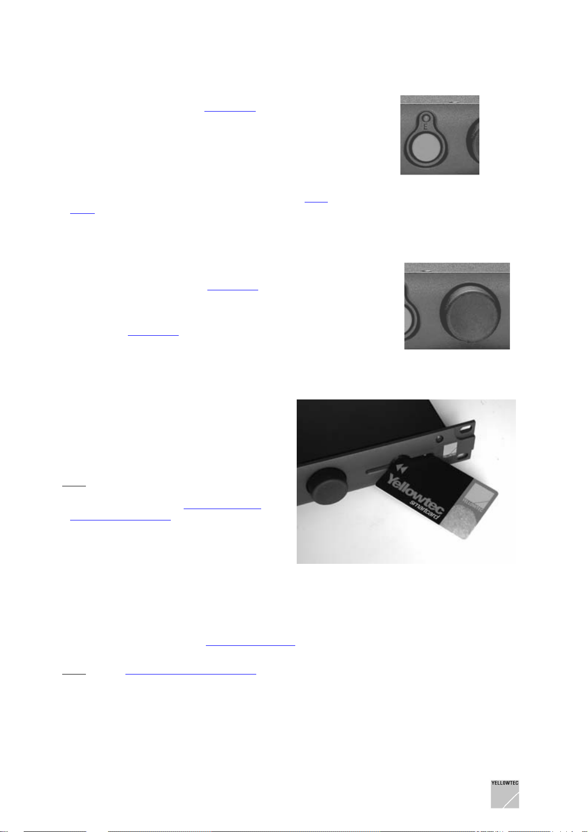
3.4 Using SmartCard
Note: There are no presets stored on the
YELLOWTEC SmartCard which is supplied with the
unit. Refer to Chapter
SOFTWARE for learning how to save data to your
SmartCard.
Inserting a new SmartCard or a SmartCard with
non-valid data (e.g. data from the previous version)
causes an error message on the VIPdigital display:
WRONG CARD or FAULTY CARD.
If valid data have been stored on your SmartCard:
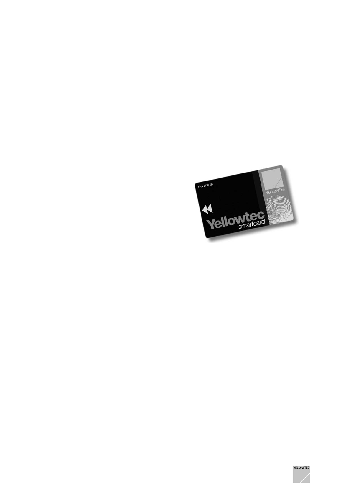
Insert a YELLOWTEC SmartCard
Please make sure that the gray double arrow of the
card is on the top, pointing to the front to the unit
(the chip is upside down).
VIPremote – THE REMOTE
into the card slot.
Once the card has been inserted, the LED of the previous selected preset button will blink to indicate
that the SmartCard has been detected, but none of its presets were loaded. At this time, the current
preset is still active.
The three Preset Recall buttons allow an access to the three presets stored on the SmartCard. Select
one of the three card presets. The display now shows the name of the card holder in the upper line and
the name of the preset below.
VIPdigital Manual 4.0 Yellowtec 2004 Rev. 26.07.2004 Page 10
Page 11

Once the SmartCard has been removed, the LED of the preset loaded last will blink again to indicate
a new access to the internal preset. At this time, the preset loaded last by the SmartCard will be
active. Press one of the three buttons to load an internal preset.
Note: Use the VIPcon configuration software to configure VIPdigital for an alternative option of
SmartCard reading: Then a SmartCard preset will be activated as soon as the Card in inserted.
As another option SmartCard reading may be disabled.
3.5 The Enter button
The green Enter button switches the unit temporarily to the Enter mode. Here, different global system
options of your VIPdigital which are independent of the preset loaded may be set. Among others, this
includes the upper level indicator, an assignment of the three presets which can be loaded
immediately on the front panel as well as the display contrast.
Keeping the Enter button pressed causes VIPdigital to show the Enter mode by a fast blinking of the
LED above the key. If no other entries are made, the mode will be terminated after some seconds and
VIPdigital will again be in the normal operating mode. Refer to the chapter Unit Description for more
details, reading the topic
The Enter Mode.
3.6 First audio connections
If you not only wish to view, but also wish to listen for a short test how the presets are functioning, you
may apply an analog signal with line level (CD player, mixer output etc., preferably speech) to Analog
Input 1.
In first line, VIPdigital is a processor for microphone signals. However, the internal presets have been
configured with a gain of 0 dB in the delivery state for reasons of safety to avoid feedback and
unintentional loud levels during the first setup. In addition, the phantom power is deactivated in the
default presets.
Of course, you may adapt the gain to your individual needs later at any time, using the
Windows software.
The following is the recommended procedure for a short test setup:
1) Connect the analog line source to the XLR Analog Input 1 on the back panel of the unit.
2) Connect the Analog Left Out/Right Out analog outputs to the line inputs of a mixer or a
monitor unit.
3) Alternately press the Preset Recall buttons1, 2 and 3 and note the differences in sound.
Note that the audio level of your test signal is relevant. The settings of some audio modules e.g.
compressor and expander are related to the input level. You can check the input level tendency on the
upper LED-segment level indicator on the frontpanel of the unit.
VIPremote
VIPdigital Manual 4.0 Yellowtec 2004 Rev. 26.07.2004 Page 11
Page 12
4 UNIT DESCRIPTION
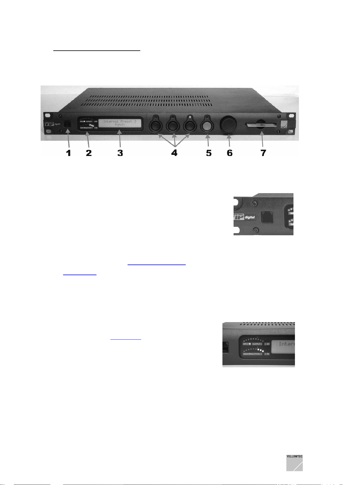
4.1 Front panel
4.1.1 Remote Control RJ12 (1)
This socket is a serial RS232 interface in the RJ12 connector
format which can alternately be used for the RS232 interface on
the back panel.
It is offered to connect a VIPdigital installed in the rack to your
PC. Thus, you will always have a quick access to permanently
installed units, using a laptop for example.
Contact your dealer for an adapter on a 9-pin D-sub connector
as an accessory to connect PCs with the traditional serial
interface sockets.
All functions are identical with the
Refer to
the connector.
PinOut Table in the chapter TECHNICAL DRAWINGS/DESCRIPTIONS for an assignment of
Remote Control D-Sub connector on the back panel.
4.1.2 Level Indicators (2)
Two bent LED instruments each with 9 segments can be found
here.
The upper instrument optionally indicates the input or output
level of the processor. The
in the Enter mode for a transfer; the current type of display
(input or output) is shown by 2 LEDs below the instrument.
There is a reference-level mark in between the 6. and 7.
segment (level tendency meter).
The lower LED instrument shows the level reduction performed
by the dynamic functions of the processor in relation to the input
level. The 0 dB position of this instrument is on the right side (all
LEDs off).
Meter Mode menu item can be used
On the right side of the two LED instruments there are two other individual LEDs:
- NT (network technology) will light up when the unit is controlled in real time by your PC via the
VIPremote software.
- Ph will light up when the phantom power of the selected input is activated.
VIPdigital Manual 4.0 Yellowtec 2004 Rev. 26.07.2004 Page 12
Page 13
4.1.3 Function Display (3)
This display is designed to show the active preset as
well as the different menu options in the
If one of the internal presets is active, the upper line of
the display will show Internal Preset followed by its
number and the lower line will show its name. When a
SmartCard is inserted in the
display line will show the name of the card holder, while the
name of the internal presets still active can be viewed in the
lower line. At the same time, the LED of the active Preset button
will blink. If one of the presets on the SmartCard is loaded by
pressing a
show the name of the SmartCard preset now activated.
Use the VIPcon configuration software to configure
Note:
VIPdigital for an alternative option of SmartCard reading: Then a
SmartCard preset will be activated as soon as the Card in
inserted.
If the
the display is used for guiding the user through the different
options of this mode.
Preset Recall button, the lower line of the display will
Enter Mode is activated by pressing the green Enter key,
Card Slot, the upper
Enter Mode.
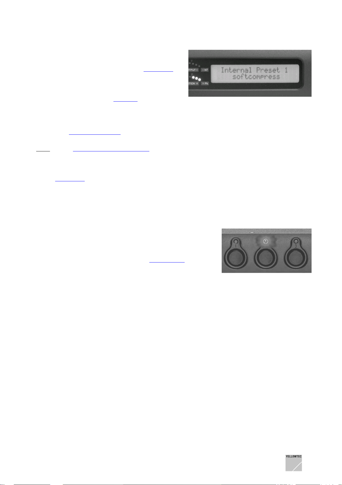
4.1.4 Preset Recall (4)
These three buttons are designed to select the active preset. If
no SmartCard is inserted, the buttons are used to load three
pre-defined presets. Which of the three presets of the VIPdigital
these are, can be defined freely, using the
item in the Enter mode (green button).
If a SmartCard
select the three presets stored on the card.
A red LED exists above each of the three buttons to indicate
that the respective preset is active. If a SmartCard is inserted or
removed, the LED of the preset loaded last will blink. In this way
the processor indicates that the current preset is still active, but
the new storage medium (internal memory or SmartCard) is
read out when the Preset Recall button is pressed next.
inserted, use the Preset Recall buttons to directly
Assign Preset menu
VIPdigital Manual 4.0 Yellowtec 2004 Rev. 26.07.2004 Page 13
Page 14
4.1.5 Enter (5)
The Enter button activates the Enter Mode for configuring
different processor functions independently of the presets.
Pressing the button causes the display to show select ACTION
in its upper line and ESCAPE below it. At the same time, the
LED of the Enter button will blink. If no other entry is made, the
mode will be terminated after a few seconds, and VIPdigital
returns to the normal operating mode. Turning the Selector
button on the right side of the Enter button selects the different
menu options of the Enter mode. Refer to the section
Mode for detailed information.
Enter
4.1.6 Selector (6)
The Selector is a rotary transducer used for selecting and
setting the menu options in the
pressing function which is identical to the function of the Enter
key. Therefore, you may also call the Enter mode by pressing
the Selector and select menu items there in the same way.
(Refer to the
Enter Mode).
Enter Mode. It has an additional
4.1.7 Card Slot (7)
The card slot is exclusively designed for an
acceptance of the SmartCard provided for
VIPdigital. Do not use no other storage media.
Please note that the gray double arrow of the
card points upwards as shown in the figure on the
right side, and points to the front to the unit (the
chip is on the bottom).
There are no presets stored on the
Note:
YELLOWTEC SmartCard which is supplied with
the unit. Refer to Chapter
REMOTE SOFTWARE for learning how to save
data to your SmartCard.
Inserting a new SmartCard or a SmartCard with
non-valid data (e.g. data from the previous
version) will cause an error message on the
VIPdigital display: WRONG CARD or
FAULTY CARD.
When a SmartCard with valid data
name of the card holder, while the name of the internal preset still active can be viewed in the lower
line. At the same time, the LED of the Exit Preset button will blink. If one of the presets on the Smart
Card is loaded by pressing the
of the display will show the name of the card preset now activated.
VIPremote – THE
is inserted in the Card Slot, the upper display line will show the
Preset Recall button, the lower line of the display will show the name
Use the VIPcon configuration software to configure VIPdigital for an alternative option of
Note:
SmartCard reading: Then a SmartCard preset will be activated as soon as the Card in inserted.
As another option you can disable SmartCard reading.
VIPdigital Manual 4.0 Yellowtec 2004 Rev. 26.07.2004 Page 14
Page 15

4.2 The Enter Mode
Optionally, the Enter mode is activated with the green Enter key or by pressing the rotary Selector
button arranged on its rights side. In this mode different processor functions which are independent of
the preset selection may be configured and can be accessed via a menu system (see below).
Pressing the button causes the display to show select ACTION in its upper line and ESCAPE below it.
At the same time, the LED of the Enter key will blink. Turning the Selector button calls the different
menu options in the Enter mode. Having selected the desired menu item, you may activate it by
pressing Enter again or using the Selector. Now, the selected parameter may be edited by turning the
Selector.
Note:
If VIPdigital, after an activation of the Enter mode, does not register an entry for approximately 5
seconds, the Enter mode is exited automatically and the unit is returned to the normal operating mode.
4.2.1 Assign Preset
In the default state the first three internal Presets stored in VIPdigital can be directly selected on the
front panel, using the
This function can be used to change the selection.
1) Remove a possibly inserted SmartCard
preset is to be assigned.
2) Press the green Enter key or the Sele ctor button to change to the Enter mode. The display
shows the select ACTION and ESCAPE below it.
3) Turn the Selector clockwise to call the ASSIGN PRESET menu item.
Preset Recall buttons 1, 2 and 3.
and press the Preset Recall button to which a new
4) Acknowl edge the selection by pressing the Enter key or the Selector.
5) Turn the Selector to select the pre set wh ich is to be assigned to the Preset Recall button
selected in 1). The corresponding LED will blink.
6) Acknowl edge the assignment by pressing the newly defined Preset Recall button. The LED
will now light continuously. The upper line shows the number of the newly assigned preset, the
lower line its name.
7) Exit the Enter mode by changing to the ESCAPE menu item and pressing the Enter key or
simply wait until the Enter mode is exited automatically.
Note:
This function may be disabled as a part of the VIPdigital configuration. Refer to VIPcon – The
Configuration Software.
Note: An Assign Preset setting is stored in a cap-buffered RAM for approx. 24 hrs. after the unit has
been switched off. After this time VIPdigital will return to the default setting.
4.2.2 Meter Mode
This menu item allows the upper Level Indicator to toggle between the display of the input and output
level independent from the setting loaded by the
1) Press the green Enter button or the Selector button to change to the Enter mode. The display
shows the select ACTION message and ESCAPE below it.
2) Turn the Selector clockwise until the METER MODE menu item is called.
3) Acknowl edge the selection by pressing the Enter key or the Selector.
VIPcon configuration software. Proceed as follows:
4) Switch over the level instrument by turning the Selector between Input Meter and Output
Meter. The appropriate status LED below Level Indicator will light up.
5) Wait for some seconds until the Enter mode is exited, or press ENTER to change to a higher
level in the menu system to select another menu item.
Note:
A Meter Mode setting is stored in a cap-buffered RAM for approx. 24 hrs. after the unit has been
switched off. After this time VIPdigital will return to the setting loaded by
VIPdigital Manual 4.0 Yellowtec 2004 Rev. 26.07.2004 Page 15
VIPcon .
Page 16

4.2.3 State
This menu item is exclusively designed to display the valid scan rate (44.1 or 48 kHz). Entries are not
possible here. Proceed as follows:
1) Press the green Enter button or the Selector button to change to the Enter mode. The display shows the select ACTION message and ESCAPE below it.
2) Turn the Selector clockwise until the STATE menu item is called.
3) Acknowledge the selection by pressing the Enter key or the Selector. Read the displayed scan
rate.
4) Wait for some seconds until the Enter mode is exited automatically, or press ENTER to
change to a higher level in the menu system to select another menu item.
4.2.4 Contrast
This option is designed for setting the display contrast. The control range is 0 to 100 %. Proceed as
follows:
1) Press the green Enter button or the Selector button to change to the Enter mode. The display
shows the select ACTION message and ESCAPE below it.
2) Turn the Selector clockwise until the CONTRAST menu item is called.
3) Acknowledge the selection by pressing the Enter button or the Selector. Turn the Selector until
the display has a contrast which is convenient for you. View the display in a view angle which
is also relevant in later applications.
4) Wait for some seconds until the Enter mode is exited automatically, or press ENTER to
change to a higher level in the menu system to select another menu item.
Note:
A contrast setting is stored in a cap-buffered RAM for approx. 24 hrs. after the unit has been
switched off. After this time VIPdigital will return to the default setting (100%).
4.2.5 Escape
This option is designed to exit the Enter mode. Turn the Selector to select a menu item and press the
Enter key or the Selector. The Enter mode is exited, and the LED above the Enter key extinguishes.
VIPdigital Manual 4.0 Yellowtec 2004 Rev. 26.07.2004 Page 16
Page 17

4.3 Back panel
4.3.1 Power supply
(A)
On the left side of the back panel there is an inlet connector for non-heating apparatus for the power
supply and a power switch. Connect your VIPdigital to your local power supply. The unit is equipped
with a switched-mode power supply and can be operated on 90-240V AC 50-60Hz without any
transfer.
Always follow the local safety regulations! Also, read the safety information below!
Please note that VIPdigital is only deenergized via the power switch on the rear side of the unit!
Disconnect the mains plug prior to opening the housing in each case!
4.3.2 Audio connections
VIPdigital is a digital signal processor with a mono-input and stereo-outputs. The selection of the
active input (Analog In 1, Analog In 2, Digital L or Digital R) is a parameter of the selected preset,
created with the VIPremote software.
Adapting VIPdigital input and output reference levels to the studio environment can be set within the
VIPcon configuration software using the Input Levels and Output Levels options.
Additional gain settings of the analog and digital signal inputs incl. microphone pre-amplification can
be performed in real time, using the
All signal outputs can be used simultaneously.
Refer to the chapter Technical Drawings/ Descriptions, sections
details on the audio connections.
4.3.2.1 Analog In 1 and 2
(Con 3 / Con 4)
Input Module of the VIPremote software.
Technical Data and PinOut Table for
The two electronically balanced analog inputs in the XLR format are suitable for a connection of both
microphones and high-level line signal sources. The gain of the inputs and the switching of phantom
power for microphone operation are controlled in real time by the
software. These settings are part of the selected preset.
The reference level of the input can be set using the
configuration software.
VIPdigital Manual 4.0 Yellowtec 2004 Rev. 26.07.2004 Page 17
Input Levels control within the VIPcon
Input Module of the VIPremote
Page 18

4.3.2.2 Analog Left Out and Right Out
(Con 5 / Con 6)
These two electronically balanced analog outputs in the XLR format provide the stereo-outpu t signals
of the processor at line level. The reference of the analog outputs can be set using the
control within the VIPcon configuration software.
Note: VIPdigital is a one-channel design. Only the Reverb Module in VIPremote produces a stereo
signal. In all other cases audio signal of left and right channel are identical.
Output Levels
4.3.2.3 Analog Hybrid-Out
(Con 7)
This electronically balanced analog output in the XLR format provides the audio signal tapped after the
Input Module of VIPremote. The reference level of this output can be set, using the Output Levels
control within the VIPcon configuration software.
The hybrid output transmits the “dry” input signal of the processor after a source selection and a level
adaptation, but before the subsequent “effect” signal processing with EQ, compressor and oth er
modules. This is designed to make an uncompressed and unprocessed signal available for a
connected telephone hybrid.
4.3.2.4 Digital AES/EBU-Sync/In
(Con 8)
This digital input corresponds to the AES/EBU standard and can be used as an audio signal input as
well as an external synchronization input. Since VIPdigital exclusively processes a single-channel
input signal, please decide on which of the two signals (L or R) of the two-channel AES/EBU input is to
be processed. Use the input select options of the
The reference level i.e. headroom setting for this input can be set using the
the VIPcon configuration software.
The
Synchronisation option within the VIPcon configuration software allows a definition as whether
VIPdigital is to synchronized internally or to be synchronized externally via the digital signal (AES/EBU
audio signal or AES/EBU blank frame) applied to this socket. Since the digital input is equipped with a
sample rate converter, the processor may be internally synchronized even if digital audio signals are
processed.
Input Module within the VIPremote software.
Input Levels control within
4.3.2.5 Digital AES/EBU-Out
(Con 9)
This digital output complies with the AES/EBU standard and provides the stereo-output signals of the
processor. The reference level of the digital outputs can be set, using the
the VIPcon configuration software.
The reference level i.e. headroom setting for this output can be set using the
within the VIPcon configuration software.
Output Levels control within
Output Levels control
Note:
VIPdigital is a one-channel design. Only the Reverb Module in VIPremote produces a real stereo
signal. In all other cases audio signal of left and right channel are identical.
VIPdigital Manual 4.0 Yellowtec 2004 Rev. 26.07.2004 Page 18
Page 19

4.3.3 Remote Control
4.3.3.1 Remote Control D-Sub
(Con 1)
This serial interface is a 9-pin D-sub connector (DB9). This socket can alternately be used for the
Remote Control RJ-12 connector on the front panel.
Use this port for connecting your Windows PC. Refer to the
Refer to the chapter Technical Drawings/ Descriptions,
Connection to the computer for details.
Pin Out Table, for the pin assignment.
4.3.3.2 Control-Out/In
(Con 2)
This control interface is designed as a 15-pin D-sub connector (DB15) and includes trigger outputs
and inputs (GPOs and GPIs) for external control tasks. Refer to the following chapter for more details
and to the chapter Technical Drawings/ Descriptions,
Pin Out Table, for the pin assignment.
4.3.3.3 Technical data Control-Out/In (GPO/GPI)
GPO : The outputs are of the OPEN COLLECTOR type.
If the output is active, it will establish a low impedance connection to 0V. In the non-active state it has
a high resistance.
Connect only loads whose current is limited to a maximum of 50mA and whose voltage is within the
range of 0V...30V.
For simple control application VIPdigital can provide the 5V and 12V auxiliary voltages which can be
used for such purposes with restrict ions.
IMPORTANT: A maximum of 100mA may be taken from the auxiliary voltages. Do not use these
auxiliary voltages to control loads which might cause electrical interferences return to the unit. The
same applies for the cables connected to these ports.
DO NOT TRANSMIT THE AUXILIARY VOLTAGES OVER LONG CABLE WAYS. IMPROPER
HANDLING OF THE AUXILIARY VOLTAGES OR A SHORT CIRCUIT MAY RESULT IN
FUNCTIONAL FAULTS OR DAMAGE TO YOUR VIPdigital.
GPI: The inputs are C-MOS compatible.
If the input is to be activated, a connection must be established to 0V, or a voltage less than +1V must
be applied.
If the input remains open or a voltage +3.5V...+12V is applied, the input will not be active.
IMPORTANT: Only voltages within the range of 0V...+12V (absolute maximum +15V) may be applied.
NON-COMPLIANCE WITH THE ADMISSIBLE INPUT VOLTAGE MAY RESULT IN FUNCTIONAL
FAULTS AND DAMAGE TO YOUR VIPdigital.
Note:
Refer to the GPI/GPO Circuit Examples in the chapter TECHNICAL DRAWINGS/
DESCRIPTIONS for connection examples.
VIPdigital Manual 4.0 Yellowtec 2004 Rev. 26.07.2004 Page 19
Page 20
5 SOFTWARE INSTALLATION
For the installation of the software package for VIPdigital a PC running Windows 95 or higher is
required.
We recommend to delete or relocate short cuts which belong to the older version(s) of the VIPdigital
software. This can avoid the unintentional use of an older program version instead of the current
version.
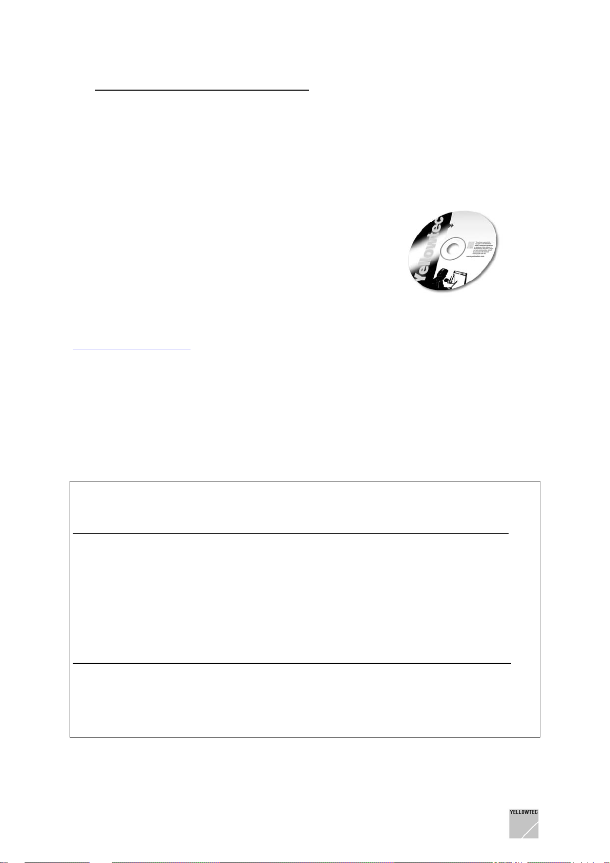
5.1 Installation from the CD-ROM
Insert the supplied CD-ROM into the CD drive of your PC and start
the SETUP.EXE installation routine. The software will guide you
through the installation process conveniently.
All required data is copied to your computer. Parameters of your
computer will not be modified.
5.2 Installation from a ZIP-file
If you receive the VIPdigital software as a ZIP file (e.g. as a download from our website
http://www.yellowtec.com/), you can open the ZIP file using the software WinZip (which should be
installed on your Windows PC as a part of Windows). Normally WinZip is started by double clicking a
ZIP file.
WinZip will extract all files into a new folder. Find the SETUP.EXE file in this folder.
A double click on SETUP.EXE starts the installation program, which will lead you automatically
through the installation process. If required a new folder and new short cuts will be created d uring the
installation process.
The update of your Windows PC is finished when SETUP.EXE is completed.
5.3 Info: The main software components of VIPdigital
Application file name location function
VIPcon VIPcon.exe Windows PC enter and transfer basic configuration/
perform firmware updates
VIPremote VIPremote.exe Windows PC remote control of sound parameters/
create sound presets
VIP Firmware VIPfirmw402.vup 19“ Unit 19” Unit firmware, DSP program file
(*402* stands for version number 4.02, may differ when using other versions)
Application ... creates ... file type file name ending
VIPcon configuration file VIPdigital Configuration file .DVP
VIPremote internal preset file VIPdigital Presets (100 presets) .VIP
VIPremote SmartCard preset file VIPdigital Presets (3 presets) .VSM
VIPremote preset file VIPdigital Single Preset .VPR
Only by using all 3 components of the current program version (VIPcon, VIPremote and VIP Firmware)
the whole functional range of VIPdigital can be achieved.
VIPdigital Manual 4.0 Yellowtec 2004 Rev. 26.07.2004 Page 20
Page 21
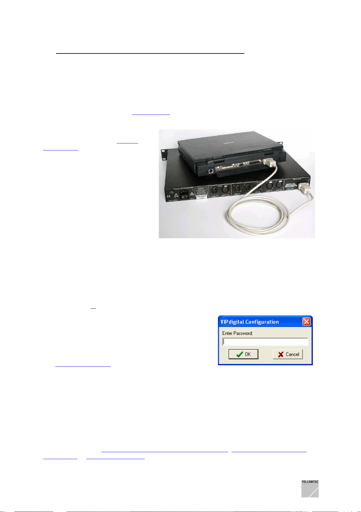
6 CONNECT VIPdigital TO THE COMPUTER
6.1 Installing the connection
To use the two VIPcon and VIPremote applications included in the VIPdigital scope of delivery, a
serial connection must be established between your VIPdigital and your PC.
To establish a connection to your PC, use a standard serial cable (in the scope of delivery). Connect a
free serial port on your PC to the
Alternatively, you may use the serial
interface on the front panel
Control RJ12 of VIPdigital - e.g. for a
temporary connection to a laptop if
VIPdigital is installed in a 19” rack. As
an accessory your dealer can offer an
adapter on a 9-pin D-sub connector to
allow PCs with traditional serial
interface sockets to be connected.
If your PC is not equipped with a serial
port (as a number of laptop computers
are) but provides a free USB port you
may as well use a common USB to
serial converter.
RS232 socket on the back panel of the unit.
Remote
6.2 Standard Application Start-up Procedure
1. Install the serial connection
2. If you were working with VIPremote or VIPcon before in off-line mode, exit both applications
3. Start VIPcon or
4. VIPcon only (skip for VIPremote)
VIPcon provides password protection.
In the upcoming dialog window enter your password
or the default password dvp and click “OK”.
More information about VIPcon password protection see
Chapter VIPcon - The Configuration Software, section
Password Protection
5. That’s all! VIPcon or VIPremote application window comes up. Now it is your turn to …
- Create Co nfiguration setups with VIPcon
- Update the firmware of your VIPdigital with VIPcon
- Control the sound settings of your VIPdigital with VIPremote in realtime
- Create so und presets with VIPremote and save them to your VIPdigital, SmartCard
or your PC
VIPremote
Refer to the chapters
SOFTWARE or UPDATING VIPdigital for explicit decriptions.
VIPdigital Manual 4.0 Yellowtec 2004 Rev. 26.07.2004 Page 21
VIPcon – THE CONFIGURATION SOFTWARE, VIPremote – THE REMOTE
Page 22

6.3 Troubleshooting
If VIPremote or VIPcon cannot connect to your VIPdigital, the following window appears:
Note 1
: Text may differ
depending on your PC
operating system
Note 2
: When you now
prompt the “YES” button,
the application you started
will open in off-line mode
Click “NO” to proceed for on-line operation:
- Chec k whether the serial connection has been installed properly
- Chec k whether the power of your VIPdigital is switched on
- As both VIP applications scan the COM ports at start-up only, consider to first install the serial
connection and then start the application.
- Chec k whether the COM ports of your PC are available or whether they are used by other
applications or are reserved/deactivated.
- VIPremote and VIPcon ca n be active at the same time in off-line mode but they may collide in
on-line mode, i.e. when they try to connect to the same VIPdigital. Exit both applications and
start the one you want to work with again.
- The standard start-up routine scans serial ports COM1 … COM4 on your PC. If your
VIPdigital is connected to a higher port number, proceed like described in the following
section
- If you are using a USB to serial converter to connect to your VIPdigital, check whether the
driver application of your converter emulates a COM port with a number higher than 4. If so,
proceed like described in the following section
Assigning COM Ports.
Assigning COM Ports.
Restart your VIP application.
VIPdigital Manual 4.0 Yellowtec 2004 Rev. 26.07.2004 Page 22
Page 23

6.4 Assigning COM Ports
If your VIPdigital is connected to a higher port number than COM4, or if you want your VIP application
to connect to a dedicated COM port, perform the following steps:
(# stands for any COM port number available on your PC)
1. Exit VIPremote/VIPcon
2. In Windows Explorer, open the VIP program folder
3. Create a short-cut of VIPremote.exe and/or VIPcon.exe
4. With a mouse click (right button) open the properties window of the short cut(s)
5. There is an entry called “target”. Without changing any character of the entry, add the following
characters to the end: “ -com #”. Make sure that there is one space character in front of the dash
and another one in front of the #.
6. Click “Apply”, then click “OK”.
7. Not required, but recommended: Rename the short-cut e.g. VIPremote_COM#/VIPcon_COM#
8. Double clicking the short-cut will start VIPremote/VIPcon in such way that only COM# port is
scanned for a connected VIPdigital.
6.5 Connecting several VIPdigital to your PC
A precondition for this mode of operation is that you are familiar with the previous section Assigning
Com Ports.
In the following we give an example to operate 3 VIPdigital with 3 VIPremote application windows:
- Create 3 short-cuts according to the procedure described in the previous section. Edit the
target entries in such way, that the first one refers to COM1, the second one to COM2 and the
third one to COM3. Rename them VIPremote_COM1 / VIPremote_COM2 /
VIPremote_COM3.
- Connect 3 VIPdigital to COM ports 1 …3 of your PC.
- Double click on short-cut VIPremote_COM1. A VIPremote application window will open which
is related to COM1 and the VIPdigital connected to it.
- Double click on short-cut VIPremote_COM2. Another VIPremote application window will open
which is related to COM2 and the VIPdigital connected to it.
- Double click on short-cut VIPremote_COM3. One more VIPremote application window will
open which is related to COM3 and the VIPdigital connected to it.
- Now 3 VIPremote application windows are controlling 3 VIPdigital at the same time. Only one
can be edited at a time. Click on a window to activate it.
Starting from this example …
- vary the number of connected VIPdigital
- use different COM port nu mbers
- use VIPcon the same way!
There is not a particular limit in number of application windows allowed to be open at the same time,
but always reassure yourself by tests on your specific PC workstation if operation is accurate.
VIPdigital Manual 4.0 Yellowtec 2004 Rev. 26.07.2004 Page 23
Page 24

7 VIPcon - THE CONFIGURATION SOFTWARE
This chapter gives you a detailed description of the functional range of VIPcon.
At this point we assume
- you have perf ormed the software installation
(Chapter
- you have connected your VIPdigital to your PC
(Chapter CONNECT VIPdigital TO THE COMPUTER
SOFTWARE INSTALLATION)
7.1 Start and end of program
VIPcon and VIPremote can be active at the same time in off-line mode but they may collide in on-line
mode, i.e. when they try to connect to the same VIPdigital. If applicable exit VIPremote now.
Start VIPcon via the Windows Start Menu program entries. If you wish VIPcon to be started via the
Windows Explorer: the name of the program file is “VIPcon.EXE“ (the default installation path is
C:\Program files\Yellowtec\VIPdigital …).
VIPcon will start with standard entries. You may modify the entries to create a configuration according
to your requirements.
7.2 Password protection
VIPcon provides password protection.
During each start of a program you are prompted to enter a password.
The password is dvp in the state of delivery.
Note:
Refer to the chapter
Change Password for further information on the Password topic.
To exit VIPcon, click on the X symbol in the upper right corner or select the Exit option in the file
menu.
VIPdigital Manual 4.0 Yellowtec 2004 Rev. 26.07.2004 Page 24
Page 25

7.3 Online operation
At this point we assume, that a data link in between your PC and your VIPdigital is established and
working. If not, or if you have any further questions concerning this subject, please go back to Chapter
CONNECT VIPdigital to your COMPUTER.
VIPcon is designed for configuring your VIPdigital. First of all, perform the basic settings and t ran sfer
them to VIPdigital.
Note:
Your settings will not be transferred until the Save to Unit command is selected.
VIPdigital will store your settings in its non-volatile memory.
Conversely, you may also load the configuration stored in your VIPdigital to VIPcon for checking and
editing. (Refer to:
Load from Unit)
7.4 Offline operation
Also, you may work with VIPcon offline, i.e. without any VIPdigital processor connected.
During the start of program VIPcon will search for a connected VIPdigital on the serial interfaces of
your PC. If no VIPdigital is found, the following dialog will appear (the text contents may vary
depending on the PC).
Clicking on the YES button starts VIPcon offline. In offline operation mode you may load configuration
files (*.dvp) already stored in your PC, edit them and store them again.
In addition, this operating mode is useful for a familiarisation or for demonstration purposes.
VIPdigital Manual 4.0 Yellowtec 2004 Rev. 26.07.2004 Page 25
Page 26

7.5 Menu: File
7.5.1 Sub-menu: New
To create a new configuration file, select New.
If a configuration has already been opened, this will be closed by the program. When creating a new
configuration you will find standard entries which can then be modified according to your
requirements.
Note: Since the current configuration is closed when New is selected, do not forget to save the
modifications before (> Save; > Save as)!
7.5.2 Sub-menu: Open
Opens an existing configuration file in the dvp format (*.dvp). The normal Windows dialog will appear
for finding the file.
7.5.3 Sub-menu: Save
Saves the current configuration.
If this configuration is saved for the first time, the “Save file as…” Windows dialog window will appear.
Enter a name for the configuration here and define the storage location. The *.dvp will automatically
be appended to the file name.
7.5.4 Sub-menu: Save as
Entering this command displays the “Save file as …” Windows dialog window. Enter the name for the
configuration here and define the storage location. The *.dvp-Suffix will be appended to the file name
automatically.
Use this command to save a configuration under several names or in different memory locations.
Note:
VIPdigital Manual 4.0 Yellowtec 2004 Rev. 26.07.2004 Page 26
Page 27

7.5.5 Sub-menu: Change Password
VIPcon provides password protection.
During each start of the program you will be prompted to enter a password.
Note:
The password is dvp in the state of delivery.
Use the Change Password dialogue to change the password.
Once you have entered your new password, you must acknowledge it by a repeated entry.
If you wish to use VIPcon without any password, leave the two entry lines in the Change Password
window empty. A password will no longer be requested from the next program start.
7.5.6 Sub-menu: Exit
Exits the VIPcon configuration software. Remember to save modifications before an exit.
VIPdigital Manual 4.0 Yellowtec 2004 Rev. 26.07.2004 Page 27
Page 28

7.6 Menu: Unit
Note:
The functions in this menu refer to the data exchange between VIPdigital and your PC. If the
configuration software could not find a connection to a VIPdigital during the start, these functions will
not be available and the menu shows gray color.
If required, establish a connection between VIPdigital and the PC and restart the configuration
software (the serial ports of your PC are only scanned during the start of the software).
For details connecting a VIPdigital, refer to Chapter
CONNECT VIPdigital to your COMPUTER
7.6.1 Sub-menu: Save to Unit
This command transfers the parameters set in your configuration software to VIPdigital. Your
configuration is saved to the internal non-volatile memory of VIPdigital. Data stored there before will
be overwritten.
7.6.2 Sub-menu: Load from Unit
Loads a configuration stored in the internal non-volatile memory of VIPdigital to the configuration
software. The configuration may be edited here and reloaded, if required. Or, save a configuration as
a file in the PC.
VIPdigital Manual 4.0 Yellowtec 2004 Rev. 26.07.2004 Page 28
Page 29

7.7 Menu: Firmware Update
This option allows a replacement of the operating software (firmware) of VIPdigital by a more current
version.
: The function in this menu refers to the data exchange between VIPdigital and the PC. If the
Note 1
configuration software could not find a connection to VIPdigital during the start, these functions will not
be available and the menu will show gray color.
For details connecting a VIPdigital, refer to Chapter
Note 2: Refer to the chapter Technical Drawings/ Descriptions under Update VIPdigital for detailed
update instructions.
We strongly recommend a firmware update only after you have read these update instr uctions
completely.
In addition, take a look at our homepage under
whether or not an update is available for VIPdigital.
Select Firmware Update.
The following warning window appears on the PC screen:
CONNECT VIPdigital to your COMPUTER
http://www.yellowtec.com from time to time as to
VIPdigital Manual 4.0 Yellowtec 2004 Rev. 26.07.2004 Page 29
Page 30

Note: A transmission of unsuitable or faulty data or interruptions during the data transmission to the
base unit may corrupt the function of VIPdigital permanently. In this case the unit can only be
commissioned by the manufacturer.
Enter the file name (see below) of the new firmware to be transferred into the text line, e.g.
VIPfirmw401.vup (this designation is an example only).
If the firmware is in the same folder as the active configuration software, the entry of the file name will
suffice. If the firmware is not
complete path, e.g.. C:\Yellowtec\VIPdigital/VIPfirmw401.vup (an example only
Click on the YES button if you are sure that your entries are correct.
The progress of transmission is shown (window: Processing...) Never interrupt this process.
After successful transmission both Processing window and Update window clo se autom atically.
in the same folder as the active configuration software, enter the
)
7.8 Menu: Help
7.8.1 Sub-menu: Help F1
Selecting this sub-menu opens the online manual with Acrobat Reader. Instead, the key F1 may be
pressed.
Refer to the chapter Prior to Beginning / Manual Conventions /
Screen Use for detailed information.
7.8.2 Sub-menu: About
Calls the Info window, displaying the software and
firmware version numbers.
Software: Configuration software ...
Firmware: VIPdigital software ...
Only the first digits with a period after the first digit
are important (e.g. 4.01).
IMPORTANT: This information is only updated
during the start of the configuration software.
To check the version number after a firmware
update, exit the configuration software. Restart the
configuration software and open the Info window.
In addition, you can also find our contact and web
address as well as the exact product designation there.
The figure on the right side shows the display for version 4.01 (example
Contact your dealer or Yellowtec for the current version.
VIPdigital Manual 4.0 Yellowtec 2004 Rev. 26.07.2004 Page 30
).
Page 31

7.9 Window: General Options
7.9.1 Range: Synchronization
Set the internal clock frequency of VIPdigital here.
Note 1:
Note 2:
VIPdigital has a Sample Rate Converter (SRC) on the digital input.
An external (house) clock can also be used for a synchronization.
7.9.1.1 Field: Frequency
48 kHz: pre-selects 48 kHz for the internal clock oscillator
44,1 kHz: pre-selects 44,1 kHz for the internal clock oscillator
7.9.1.2 Field: Sync Source
Internal: selects the internal clock oscill at or for synchronizing VIPdigital.
External: selects the external clock for synchronizing VIPdigital. The clock signal is generated from the
AES/EBU signal (or empty frame) which is applied to the digital input.
VIPdigital Manual 4.0 Yellowtec 2004 Rev. 26.07.2004 Page 31
Page 32

7.9.2 Range: Access Internal Preset
VIPdigital stores 100 Internal Presets. 3 of these presets are enabled for a direct selection via the
Preset Recall buttons. As a default preset no. 1/2/3 refer to the buttons 1/2/3.
Define here whether the assignment of the 3 enabled presets can be modified on VIPdigital (offline,
without PC).
Refer to the chapter Unit Description / Enter mode /
enabled
A modification to the preset selection on VIPdigital is possible.
disabled
A modification to the preset selection on VIPdigital is not possible.
Note:
An Assign Preset setting which has been performed on the VIPdigital unit is stored in a capbuffered RAM for approx. 24 hrs. after the unit has been switched off. After this time VIPdigital will
return to the default setting.
Assign Preset
7.9.3 Range: Preset Order
The Assign Preset function can be used in the Enter mode to assign 100 internal presets of VIPdigital
to the Preset Recall buttons. Preset Order defines the sequence in which the presets are to appear in
the display when the Selector is turned.
Order Internal Presets by number
Internal presets are sorted by a preset number
Order Internal Presets by name
Internal presets are sorted by a preset name
7.9.4 Range: Replace Internal Preset
The VIPremote software allows the 100 internal presets of your VIPdigital to be overwritten with new
data by clicking on the SAVE TO VIP button.
Activate the Enabled checkbox to enable overwriting.
If the checkbox is not activated, the Save to VIP command is disabled in VIPremote.
VIPdigital Manual 4.0 Yellowtec 2004 Rev. 26.07.2004 Page 32
Page 33

7.9.5 Range: Read SmartCard
Select among the 3 SmartCard Read options:
Soft Read Enable
When your SmartCard is inserted, VIPdigital will not accept a preset until one of the Preset Recall
buttons is pressed.
Radical Read Enable
When the SmartCard is inserted, VIPdigital will accept the preset immediately. The preset number (1,
2 or 3) active prior to insertion will be accepted.
Disable
The data of an inserted SmartCard is ignored.
7.9.6 Range: Write SmartCard
Write enabled
Presets can be saved to the SmartCard (Save to SmartCard command/button enabled in the
VIPremote software)
Write disabled
Presets cannot be saved to the SmartCard (Save to SmartCard command/button disabled in the
VIPremote software.)
7.9.7 Range: Meter Default
Input Level
After an activation the Level Indicator will show the input level.
Output Level
After an activation the Level Indicator will show the output level.
Note:
The Level Indicator shows the selections, using LEDs. The Level Indicator can be switched off
during operation at any time, using the
The Enter menu allows also switching between Input Level and Output Level.
Note:
A Meter Mode setting performed on your VIPdigital is stored in a cap-buffered RAM for approx. 24
hrs. after the unit has been switched off. After this time VIPdigital will return to the selection set in
VIPcon.
Meter Mode menu item in the Enter menu of your VIPdigital.
7.9.8 Range: Enter Button
Checkbox: Function Disabled, No Access to Menu
Click on this checkbox to disable the Enter button.
Now, only the 3 internal presets or your SmartCard presets can be selected on VIPdigital.
All other controls are disabled.
VIPdigital Manual 4.0 Yellowtec 2004 Rev. 26.07.2004 Page 33
Page 34

7.9.9 Range: Input Levels
Adapt the VIPdigital audio input levels to your studio environment here.
“0dB“ identifies the internal reference level of VIPdigital which relates to the reference mark of the
level tendency meter on the frontpanel of the unit.
Your setting should relate to the reference level of the incoming signal.
Digital Input Setting range -20dBFS ... 0dBFS
Analog Input Setting range -6dBu ... +15dBu
Example digital range
Example analog range
+4dBu.
To modify the value, use the mouse to click on the respective controller symbol and control the
desired value in 1 dB increments, using the Cursor Up or Cursor Down key.
Alternately, you may click on the controller symbol and move the mouse to the left and right side while
the left mouse button is kept pressed.
: Your incoming signal is set for 12dB headroom. Set Digital Input to –12dBFS.
: Your incoming signal provides a reference level of +4dBu. Set Analog Input to
7.9.10 Range: Output Levels
Adapt the VIPdigital audio output levels to your studio environment here.
“0dB“ identifies the internal reference level of VIPdigital which relates to the reference mark of the
level tendency meter on the frontpanel of the unit.
Your setting should relate to the reference level of the required outgoing signal.
Digital Output Unit dBFS Setting range –20dBFS ... 0dBFS
Analog Output Unit dBu Setting range -6dBu ... +18dBu
Hybrid Output Unit dBu Setting range -6dBu ... +18dBu
Example digital range
–12dBFS.
: Your following studio equipment is set for 12dB headroom. Set Digital Output to
Example analog range
Analog Output resp. Hybrid Output to +4dBu.
To modify the value, use the mouse to click on the respective controller symbol and control the
desired value in 1 dB increments, using the Cursor Up or Cursor Down key.
Alternately, you may click on the controller symbol and move the mouse to the left and right side while
the left mouse button is kept pressed.
VIPdigital Manual 4.0 Yellowtec 2004 Rev. 26.07.2004 Page 34
: Your following studio equipment works at a reference level of +4dBu. Set
Page 35

7.10 Window: Control Logic
7.10.1 Range: Trigger Outputs
VIPdigital provides 4 trigger outputs (GPOs).
These trigger outputs allow a transmission of commands to other units or to select signal lamps,
relays, opto-couplers, etc.
Select one of the functions available in theTrigger pulldown menu for each output.
A number of logic combinations with external applications result.
Refer to the
Use the Action pulldown menu to select the signal shape (e.g. Pulse or Tally) suitable for your
application. Refer to the
Refer to
Refer to the chapter Technical Drawings / Descriptions for detailed connection drawings under
GPI/GPO Circuit examples.
VIPdigital Manual 4.0 Yellowtec 2004 Rev. 26.07.2004 Page 35
Trigger Output Functions below for the functions available.
Trigger Output Actions below for the signal shapes available.
Control-Out/In in the chapter Equipment Description / Backpanel, providing the technical data.
Page 36

7.10.1.1 Trigger Output Functions
List of the functions in the Trigger pulldown menu:
Disable
No function on this output
Button 1
Activates the trigger output when Preset 1 is selected
Button 2
Activates the trigger output when Preset 2 is selected
Button 3
Activates the trigger output when Preset 3 is selected
Button E
Activates the trigger output when the Enter mode is activated
Ready
Activates the control output shortly after readiness of operation is achieved.
Note
: Trigger outputs are generated each time a change in preset selection takes place or enter mode is
activated. If for example button 1 is pressed repeatedly, this will not generate repeated trigger output
actions.
7.10.1.2 Trigger Output Actions
List of the signal form in the Action pulldown menu:
Tally
The control signal is active during the entire function duration
Pulse On
Activating the function generates a pulse. The pulse duration can be set in Pulse Duration.
Pulse Off
Terminating the function generates a pulse. The pulse duration can be set in Pulse Duration.
Pulse On/Off
Activating and terminating this function generates a pulse. The pulse duration can be set in Pulse
Duration.
7.10.2 Range: Pulse Duration
For the Pulse Trigger Output signal wave the Pulse duration can be set in the Pulse Duration pulldown
menu. Available pulse durations are
- 50 ms
- 100 ms
- 1000 ms
VIPdigital Manual 4.0 Yellowtec 2004 Rev. 26.07.2004 Page 36
Page 37

7.10.3 Range: Trigger Inputs
VIPdigital provides 4 trigger inputs (GPIs).
The trigger inputs allow commands from other units to be received to initiate actions and/or functions
in VIPdigital. Thus, functions of your VIPdigital can be “controlled remotely”.
Select a function available in the Action pulldown menu for each input.
A number of logic combinations with external applications results.
Refer to the
Refer to: Control-Out/In in the chapter Equipment Description / Backpanel, providing the technical data
among others. Refer to the chapter Technical Drawings / Descriptions for detailed connection
drawings under GPI/GPO Circuit examples.
Trigger Input Actions list below for the functions available.
7.10.3.1 Trigger Input Actions
List of the actions and/or functions in the Action pulldown menu:
Disabled
A control signal on this input is ignored
Button 1
Activates in VIPdigital the same control command as if the Preset Recall 1 button was pressed
Button 2
Activates in VIPdigital the same control command as if the Preset Recall 2 button was pressed
Button 3
Activates in VIPdigital the same control command as if the Preset Recall 3 button was pressed
Button E
Activates in VIPdigital the same control command as if the Enter key was pressed
Input Mute
Performs an audio mute in the VIPdigital audio signal chain after the Input module. Use this
Trigger Input to connect a cough button.
VIPdigital Manual 4.0 Yellowtec 2004 Rev. 26.07.2004 Page 37
Page 38

8 VIPremote - THE REMOTE SOFTWARE
This chapter gives you a detailed description of the functional range of VIPremote.
At this point we assume
- you have perf ormed the software installation
(Chapter
- you have connected your VIPdigital to your PC
(Chapter CONNECT VIPdigital TO THE COMPUTER)
- you are familiar with VIPcon and your VIPdigital is configured to match your studio
environment
(Chapter
SOFTWARE INSTALLATION)
VIPcon – THE CONFIGURATION SOFTWARE)
8.1 General
While VIPcon is responsible for the basic system configuration of your VIPdigital, VIPremote allows a
control of the audio parameters in real time. Thus, VIPremote is the actual user interface of your
processor. The modifications made here are immediately performed by the unit so that the sound
effects of your settings can be heard on the signal output. In addition, VIPremote manages the presets
stored in your VIPdigital, on SmartCard or in the PC.
VIPdigital Manual 4.0 Yellowtec 2004 Rev. 26.07.2004 Page 38
Page 39

8.1.1 Start and end of program
Start VIPremote via the Windows Start Menu program entries. If you wish VIPcon to be started via the
Windows Explorer: the name of the program file is “VIPremote.EXE“ (the default installation path is
C:\Program files\Yellowtec\VIPdigital …).
In Offline mode VIPremote and VIPcon can be active at the same time. In Online-mode they will
Note:
collide when they try to connect to the same VIPdigital. If you have worked with VIPcon before, exit
this program first.
8.1.2 Offline mode
During start-up VIPremote scans the serial ports of your PC for a connected VIPdigital. If no unit is
found, the following dialog will appear:
(The text contents may vary depending on your PC)
Click on the YES button to start VIPremote offline. In the Offline mode, for example, you may create,
edit and save preset files.
In addition, this mode is suitable for a familiarization or for demonstration purposes.
If you intend to connect to a VIPdigital unit, refer to chapter
COMPUTER, section Troubleshooting.
Note: Be aware that VIPremote only scans the serial ports during start-up. The connecting in between
your VIPdigital and your PC has to be established before program start.
CONNECT VIPdigital TO THE
8.1.3 Online mode
In Online mode you can save presets to your VIPdigital and to SmartCard. Or your can load presets
from VIPdigital and SmartCard into VIPremote, edit them and save them to your PC.
As soon as you click on a preset in the Internal Presets list or the SmartCard Presets list, your
VIPdigital switches to Remote Control operation. VIPremote then functions as a remote control for
your VIPdigital.
The VIPdigital operator controls are deactivated, and your VIPdigital display shows Remote Control. In
addition, the status LED NT lights up in the
Level Indicator Field.
VIPdigital Manual 4.0 Yellowtec 2004 Rev. 26.07.2004 Page 39
Page 40

8.1.4 Start-Up Mode
new in version 4.0!
The left-hand area contains elements for the preset administration. The preset lists are “empty ”, i.e.
settings and designations are neutral.
The buttons in the lower section of the program window are designed to transmit presets between the
PC and the processor and save or load presets to the hard disk of your PC. As a start, you may load
default presets (default.vip / default.vsm / default.vpr) by clicking on the LOAD FROM PC button (refer
Loading from the PC).
to
The right-hand larger area of the program window is deactivated. It contains a total of 14
Processing Modules for sound editing and an adaptation of the input signal. Modules are hidden in
Start-up mode.
Features of start-up mode
- presets can be loaded from your VIPdigital / SmartCard / PC without affecting audio
performance
- presets can be saved to your VIPdigital / SmartCard /PC without affecting audio performance
- only after a click on a preset from the Internal Preset list or the SmartCard Preset list the Audio
Processing Module will be activated (and fully visible) and VIPdigital switches to Remote
Control operation.
- the new start-up mode allows you smoothly to take over Remote Control of your VIPdigital
Example:
SmartCard Presets (if SmartCard is inserted) are loaded from the unit without affecting VIPdigital
audio performance. After loading, VIPremote displays in bold letters the one preset, which was
selected on VIPdigital at the time the download started (Internal or SmartCard preset). For a soft
After starting the application, click on LOAD FROM VIP. All presets, Internal Presets and
Audio
VIPdigital Manual 4.0 Yellowtec 2004 Rev. 26.07.2004 Page 40
Page 41

“takeover”, click on this very preset thus taking over Remote Control. Modify your settings, save
them to VIPdigital or to SmartCard. Exit VIPremote when your modifications are done. VIPdigital
returns to stand-alone operation (to the preset displayed in bold letters, which was active before).
Note: All functions are described more detailed in the following.
8.1.5 Help call
Click on the HELP button or press F1 if information is required.
The Online Manual is then started automatically with Acrobat Reader. Activate the Bookmark View to
navigate conveniently through the document, using the table of contents.
Refer to the chapter Prior to Beginning / Manual Conventions /
information.
Use of the Screen for detailed
8.1.6 Info window
Click on the INFO button to call the current version numbers of the software and firmware;
- VIP Remote Software x.xx (the first three digits with a period behind the first digit are important).
- VIP digital Software x.xx (firmware in VIPdigital 19” unit) is only displayed if a unit is conn ected;
otherwise, the display shows 0.00 or the last value.
- VIP.INI Version x.xx (file without user data and user access, only for service).
Refer to the chapter
Software Components of VIPdigital for detailed information.
Update VIPdigital and to the chapter Technical Drawings / Descriptions under
8.1.7 Exit VIPremote
Click on the X symbol in the upper right-hand corner of the program window
VIPdigital Manual 4.0 Yellowtec 2004 Rev. 26.07.2004 Page 41
Page 42

8.2 Audio Processing Module
8.2.1 Basic information
VIPdigital provides 14
audio processing modules
for processing your audio
signals. The sequence of
the individual modules
represents the signal path
from the input on the left
upper corner to the Limiter
module in the bottom line.
Use the shift hand symbol
to click once on the orange
lettered bar of a module
and move it to another
position, keeping the
mouse button pressed.
Release the mouse button.
The module is set to its
new position.
Thus, it is easy to modify
the sequence of the module and design the characteristics of sound editing even more exactly. The
shift hands of the modules which are no longer in their original position are highlighted.
The sequence of the modules in the state of delivery is not a random one. This sequence yields the
best results for most applications.
Note:
When default settings from older program versions are loaded, it may occur that a deviating
sequence is signalled. This is no error. The default settings have been modified meanwhile.
Only the INPUT module on the input and the DELAY, REVERB and LIMITER modules on the output
have a fixed position. The shift hand symbol is therefore missing on these modules.
As an expert user you will perform deviating settings for your special cases.
The modules are equipped with the ON and EDIT buttons (exceptions: INPUT module only EDIT and
PHASE module only ON). The ON button switches ON or OFF the function of a module. The ON-state
is identified by a symbolized green illuminated display. Thus, you can see at a glance whether and
which modules are active.
Clicking on the EDIT button opens the setting window of the respective module where the individual
parameters may be edited. The functions of the different modules are described below in detail.
Numerous setting windows contain virtual “rotary controllers” with an adjacent number field which are
used for entering parameters. Click the mouse on a rotary controller and move the mouse while the
button is pressed to the left or right side to reduce or increase the set value. The mouse pointer will
change to a plus-minus symbol.
All settings performed here will be transferred to VIPdigital immediately and can be heard at
once. Thus, the VIPremote software is the actual user interface to y our VIPdigital.
Exit a module setting window by clicking on the X button in the right upper corner.
VIPdigital Manual 4.0 Yellowtec 2004 Rev. 26.07.2004 Page 42
Page 43

8.2.2 Module: Input
8.2.2.1 Input source
Use the four buttons on the left side to select the desired input source.
MIC1 Analog input 1
MIC2 Analog input 2
DIG. L AES/EBU input, left signal
DIG. R AES/EBU input, right signal
8.2.2.2 Input Gain
The pre-amplification of the selected input is set, using the two ANALOG GAIN and DIGITAL GAIN
controllers.
Analog Gain Analog Gain controls the gain of the analog microphone amplifier before an
A/D conversion. The settable control range is 0 to +54 dB in 6 dB increments.
A setting of 0 dB corresponds to the level set for the analog inputs in the
Levels range of the VIPcon configuration software. For low-level microphone
signals higher values are normally required for analog gain (>30 dB), while
signals with a line level often do not require an analog pre-amplification (0 dB).
This parameter has naturally no influence on digital input signals.
Digital Gain Digital Gain controls the input gain on digital level. The control range is -20 to
+20 dBFS in 1 dB increments. Control is performed in the digital section of the
processor. Therefore, this parameter affects both analog and digital input
signals.
To match the analog and digital pre-amplification with your input signal, monitor the processor input
level, using the upper Level Indicators on the VIPdigital front panel. Check whether this instrument is
switched to Input; otherwise change it to Input, using the appropriate
Both gain controllers are active for analog input signals (refer to Digital Gain).
Note:
Please note that the correct setting of the analog and digital pre-amplification is crucial for an optimum
signal quality in the case of analog sources.
If the Analog Gain controller is set too high and the level is subsequently attenuated with Digital Gain,
you may hear a distorted signal because of the overdriven analog input although the level display
show no overdriving.
Conversely, you may obtain a noisy input signal if Analog Gain is set very low and the required gain is
subsequently made with the Digital Gain controller. As a thumb rule, the Digital Gain controller should
be left in its position 0 dB, and Analog Gain should be used to set a well modulated input signal. It is
not until then that Digital Gain can be used to make possible required adjustments.
Menu option in the Enter Mode.
Input
The position of the input module in the first place of the signal path is not variable.
VIPdigital Manual 4.0 Yellowtec 2004 Rev. 26.07.2004 Page 43
Page 44

8.2.2.3 Phantom Power
To supply a connected condenser microphone, Phantom Power (48V) can be applied to both analog inputs. To do so, click on the Phantom Power button.
Note: Before activating the 48V Phantom Power, check whether the connected microphone is designed
for this mode. If a signal source with line level is added, no Phantom Power must be applied to the
input normally.
WARNING: In the case of a mismatch/misadjustment your microphone or other signal source may be
damaged.
8.2.3 Module: Subsonic
This is a tool for attenuating low-frequency noise and interferences efficiently.
The Subsonic filter is a powerful adjustable high-pass filter with a slope of 18dB/ octave.
The control range for the corner frequency (-3 dB point) is 30 to 200 Hz.
The filter always operates on a maximum attenuation below the corner frequency; thus, gain setting is
not available.
In particular in the editing of speech, the Subsonic filter is an important tool for the elimination of
interferences. It can be caused by the speaker (e.g. so-called “plops” during the pronunciation of the
consonant “P”) or they enter the microphone from the speaker environment (e.g. as subsonic noise or
parasitic noise from an air conditioning system).
However, the Subsonic filter can also excellently be used for a creative sound editing, e.g. in
interaction with a low-frequency gain setting in one of the EQ-modules.
8.2.4 Module: Phase
This function is a special type within the Audio Processing module since its effect cannot be heard
immediately, but has a more technical background.
The function improves the input level range of an A/D converter or digital processing stages following
this module.
If you are not sure whether or not to activate this function, you should leave the module deactivated.
Technical background: The Phase module generates an effect known in the broadcast range as a
“phase rotation” which is to prevent a clipping by asymmetric signal amplitudes. Just the human voice
can provide an unsymmetrical signal amplitude in many cases. This may e.g. reduce the input level
range of a converter so that early distortions may occur. To counteract this effect, the phase module
sets an all-pass filter into the signal path to stabilize a signal symmetrically. From a technical point of
view, the DC-portion is taken from the signal.
In effect, a signal can be leveled higher without being distorted, i.e. the Phase module enhances the
“loudness” of the signal.
The Phase function has no parameters which can be edited, and thus no special setting window. It
can only be switched on and off.
Note:
The Phase module does not include a Phase Reverse function, i.e. a reversal of the polarity of
the audio signal as known from the input stage of audio-mixing desks.
VIPdigital Manual 4.0 Yellowtec 2004 Rev. 26.07.2004 Page 44
Page 45

8.2.5 Module: De-esser
Application: Suppression of noisy hissing sounds. The De-esser is a compressor especially
configured for a reduction of “S”- or sibilant sounds. This compressor operates on frequency
selections. This means that only certain parts of the frequency spectrum initiate control activities in the
input signal and the other signal components pass the module unchanged. This module i s an
important tool for editing speech. For example, it is used to set an especially “present” sound
character of a voice with an equalizer used at the same time without loosing control of sibilant sound s.
Theoretical background: Psycho-acoustics introduced the term of “sharpness” (S) as a measure for
the portion of high frequency and complex signal components within an audio sign al. The more highfrequency signal portions referred to the power contained are within a signal, the sharper it will be
received by people. A sinusoidal sound with a frequency of 1 kHz is perceived as a reference for a
sharpness of = 1. Higher tones and complex sound such as sibilant sounds have a sharpness of S>1.
Technical implementation: The De-esser contained in VIPdigital analyzes the sharpness of the input
signal, using a special algorithm. At the same time the spectrum is analyzed, and filter parameters
such as filter center frequency, attenuation and bandwidth are evaluated. The filter operates as a
function of the input signal within the frequency range of 2 kHz and 10 kHz so that no manual
adjustment of the center frequency is required by the user. This type of adaptive filtering makes sure,
that only these frequencies are attenuated, which are over-represented in the frequency band. The
second reason for the neutrality of sound is that its control parameters are rather depen ding on the
spectrum-analysis than on the level-amplitude of the audio signal. The sharpne ss is largely
independent of the amplitude.
Basic setting: Start your settings with a basic setting of 1.2 for the Sharpness Threshold and 2:1 for
ratio. Now determine the optimum values for the three parameters by hearing tests.
Operator controls:
Sharpness Threshold This is the threshold for the psycho-acoustic sharpness parameter. If the
sharpness of the input signal exceeds the value set here, the De-esser will be
activated and reduce the sharpness of the output signal as a function of the
values for Ratio and Bandwidth (see below). The setting range of the
parameter is between 0.8 and 1.8. Values of 1.0 or lower values result in a
strongly attenuated sound of speech signals. However, only a few and
particularly sharp hissing sounds will be detected in the maximum position.
Ratio The higher the set ratio, the higher the attenuation of the adaptive filter. The
setting range of the parameter is between 1:1 and 4:1. The De-esser is
deactivated in its 1:1 position.
Bandwidth This parameter controls the bandwidth of the adaptive filter. The higher the set
value, the broader will be the frequency range attenuated by the filter.
If you are not sure whether or not to activate this function, switch off the module.
VIPdigital Manual 4.0 Yellowtec 2004 Rev. 26.07.2004 Page 45
Page 46

8.2.6 Module: Equalizer
(four identical modules independent of each other)
VIPdigital provides four completely parametric equalizer modules which can be set and be arranged in
the signal path independently of each other. The modules numbered EQ 1… EQ 4 have identical
parameters and can thus be used within the entire audio spectrum.
Parametric equalizers are surely the most important tools for processing audio signal s, allowing
specific frequency ranges in the spectrum to be boosted or cut. Thus they can be used for a
technically motivated correction of quality defects or for a creative approach, modeling sound
characteristics.
Optionally, each module can be configured as a bell equalizer (Bell) or as a shelving equalizer in the
upper (High Shelv) or lower (Low Shelv) frequency range.
Bell Boost or cut a defined frequency range within the signal spectrum, define the
center frequency of this range with the Freq. setting – you will not influence
the signal above or below this range.
High Shelv Boost or cut the frequency range above the set frequency (Freq.). You may
use this EQ type like a specially convenient treble controller.
Low Shelv Boost or cut the frequency range below the set frequency (Freq.). You may
use this EQ type as a particularly convenient bass controller.
Gain Set the value for boost or cut. The control range is –12 dB to +12 dB.
Freq. This parameter determines the center- or corner-frequency of the filter.
Quality This parameter defines the so-called filter quality, i.e. the reverse bandwidth of
the filter. The higher the set value, the narrower the operating range of the
filter in the signal spectrum. Quality can only be set in the Bell mode; the
parameter is not available in the High Shelv and Low Shelv modes-
Basically, working with a Bell characteristic you will choose a narrow band to
suppress noise or resonance (high quality value). For empha sizing, i.e.
boosting a frequency range a broader filter setting (low-quality value) is
preferred in common applications.
VIPdigital Manual 4.0 Yellowtec 2004 Rev. 26.07.2004 Page 46
Page 47

8.2.7 Module: Expander
In practice, expanders are mostly used for suppressin g interferences (background noise, tape noise)
in modulation pauses.
Signals whose level is higher than the value set with Threshold are not influenced. These are the
signal portions you want to keep.
If the signal level is below the Threshold value, it will be attenuated. These are the signal portions (e.g.
background noise) that you want to remove.
The Threshold setting is therefore most important. The use of an expander requi res an exact
knowledge of the technical context since parts of the useful signal are possibly “suppressed” if it is set
improperly.
If you are not sure whether or not to activate this function, switch off this module.
Functions and settings in detail:
Ratio The ratio parameter defines the expansion ratio of the module. A ratio setting
of 1:2 means that if a signal level is 1 dB below Threshold level, it will be
attenuated by 2 dB. The higher the set value, the more the signal will be
attenuated by the expander. The ratio setting range is 1:1 to 1:3.0.
Threshold This parameter controls the threshold of the expander. Above the level value
defined by Threshold the expander will operate as a 1:1 gain stage. Below the
threshold the expansion ratio set with the Ratio parameter is applied to the
signals. The threshold setting range is –60 dB to 0 dB.
Output Gain This controller can be used to increase the output gain of the expander
independently of the input level. The gain setting range is 0 dB to +20 dB.
Attack This controller controls the response time of the expander. The smaller the
time constant set here, the faster the expander will respond to a signal
overriding the threshold (“Opening-time”). For the slow position of the
controller (left stop) the attack side is approximately 12 ms; for the fast
position (right stop) it is approximately 0.4 ms. These are guide values, they
vary depending on the dynamic and spectral characteristic of the input signal.
Release This controller controls the closing time of the expander. The higher the time
constant set here, the slower will be the attenuation of the signal after falling
below the threshold. For the slow position of the controller (left stop) the
release time is approximately 2.048 ms; for the fast position (right stop) it is
approximately 16 ms. These are guide values, they vary depending on the
dynamic and spectral characteristic of the input signal. Short release times are
critical. If you are not yet familiar with the handling of an expander, use
medium to extended times first.
Note:
The expander is a dynamic tool with the reverse effect of a Compressor. Its application is
especially recommended if a compressor is used at the same time.
A Compressor (or the AGC function) may often emphasize parasitic noise in signal intervals.
To avoid this, arrange an expander before the compressor (and/or AGC Module) in the signal path.
Adjust the threshold to a value higher than the parasitic noise and lower than the useful signals.
VIPdigital Manual 4.0 Yellowtec 2004 Rev. 26.07.2004 Page 47
Page 48

8.2.8 Module: AGC
AGC (Automatic Gain Control) is designed for an automatic and subtle gain readjustment if the signal
level varies.
As opposed to the compressor which responds quickly to short-term level modifications, the AGC will
only become active if the signal level is above or below the set target level over an extended time.
The use of AGC can be of great benefit for many applications, but always make sure to exactly know
the functionality and carefully set the parameters. AGC has substantial impact on the audio signal.
Always consider carefully whether or not you need this function.
Functions in detail: The control amplifier used for the AGC function references to the adjustable
Target Level. Gain is increased when the signal level is lower than target level. On the other hand, the
signal is attenuated when the signal level is higher than target level.
If the signal falls below Freeze Threshold (adjustable -20dB … -40dB), AGC Freeze function freezes
gain to the current value. Signals below freeze threshold are supposed to be signal gaps or
background noise. Freezing the current gain value prevents unintentional high levels or overdriving
when the “normal” signal is applied again.
Basically, the AGC function uses very slow time constants to ensure an subtle adaptation of the level.
The Control Velocity parameter controls the time constants used for the gain changes. The value is
expressed in dB per second.
Maximum Gain can be set from 5dB … 30dB. This gives you perfect control on the maximum impact
the AGC module can have on your audio signal.
Target Level setting range -20 dB to +20 dB
Freeze Threshold setting range -40 dB to -20 dB
Control Velocity setting range 0.3 dB/s to 1.5 dB/s
Maximum Gain setting range 5dB … 30dB
Note:
During speech intervals the level is far below the Target Level, i.e. the AGC would increase gain
normally. The Freeze function prevents an unintentional increase of gain in signal gaps.
But, if the speaker microphone receives loud background noise in speech interv als, the Freeze
function will probably not be able to distinguish between background noise and a low speech pass.
Always set FreezeThreshold carefully. If set too low, gain might be increased and bring up background
noises during a speech interval. If set too high, a low speech pass will not be increased in gain.
Under these conditions make a test as to whether or not the use of the AGC function is practicable, or
use the
Expander Module before the AGC module for a suppression of background noise.
VIPdigital Manual 4.0 Yellowtec 2004 Rev. 26.07.2004 Page 48
Page 49

8.2.9 Module: Compressor
Application: The Compressor is one of the most important tools to give audio signals more loudne ss,
especially with regard to voice processing for broadcast applications.
The Compressor reduces the dynamic range within the upper level range. Signal peaks will be
reduced. Thus, the basic gain can be set higher without overdriving the circuitry.
Note:
Keep in mind that at the end of the chain there is a limiter module available to provide perfect
overmodulation protection. Use the compressor mainly to create your so und.
A compressed signal is perceived as essentially “louder” than an uncompressed signal.
Function: In particular for the processing of speech, the compressor is an important dynamic tool,
changing the gain dynamically as a function of the input signal level and reducing the output gain as
soon as the input signal exceeds the threshold value defined by Threshold. Below the threshold the
compressor functions as a 1:1 amplifier stage.
In addition, the output gain can be increased with the controller output gain independently. This
compensates the level losses occurring during the compression. The result is a louder output level for
low input levels which will not be too loud for higher input levels – i.e. a reduced dynamic range as
compared with the original signal.
Ratio The ratio parameter defines the compression ratio of the module. A ratio
setting of 2.0:1 means that the output signal of the compressor is only
increased by 1 dB for an input level (above the set threshold) increased by 2
dB. The higher the set value, the more the reduction of the gain above the
threshold of the compressor. The ratio setting range is 1:1 to 1:10.
Threshold This parameter controls the threshold of the compressor. Below the level
value defined by Threshold the compressor will function as a 1:1 gain stage.
Above the threshold the compression ratio set by the ratio parameter will be
applied to the signal. The threshold setting range is –50 dB to +10 dB.
Output Gain This controller can be used to set the output gain of the compressor
independently of the input level. The setting range is from 0 dB to +20 dB.
Attack This controller defines the response of the compressor. The smaller the time
constant set here, the faster will be the response of the compressor to a signal
exceeding the threshold. For the slow position of the controller (left stop) the
attack time is approximately 12 ms; for the fast position (right stop) it is
approximately 0.4 ms. These are guide values, they vary depending on the
dynamic and spectral characteristic of the input signal.
Release When, after a loud sequence, the input level drops below the threshold, the
compressor applies the time constant set here to fall back to the 1:1 gain
functionality. This parameter has great impact on the sound of the processed
audio signal. Carefully adapt the value to your application (if you are not sure,
begin with medium values). For the slow position of the controller (left stop)
the release time is approximately 2.048 ms; for the fast position (right stop) it
is approximately 16 ms. These are guide values, they vary depending on the
dynamic and spectral characteristic of the input signal.
Note:
Under unfavorable conditions, the use of a compressor might bring up noise to an audible level. If
for example, a certain amount of background noise is present in the audio signal, it will be more
audible after output gain has been increased. This effect can be reduced efficiently by using an
Expander before the Compressor module.
VIPdigital Manual 4.0 Yellowtec 2004 Rev. 26.07.2004 Page 49
Page 50

8.2.10 Module: Delay
The Delay module inserts an adjustable signal delay
into the signal path. As opposed to numerous digital
effect processors, the delay is not used for a “sound”
processing, but exclusively as a technically oriented
tool for a compensation of delay times – such as for
picture-related audio post-processing for a
synchronization to the picture. In particular, the
module cannot be used for echo effects and the
like. Instead, use the
effects of the signal.
The setting range for the delay time is 0 to100 ms.
Please note that VIPdigital inserts an additional transit time for digital signal processing into the signal
path as other digital signal processors do. However, this is extremely low for this processor, using
approximately 1.5 ms. This transit time which always exists independently of the Delay module must
be added to the delay time set in the Delay module if the entire signal transit time is to be determined.
The position of the Delay module (i.e. in front of the Reverb module) is not variable as opposed to
most of the other components.
Reverb Module for handling
VIPdigital Manual 4.0 Yellowtec 2004 Rev. 26.07.2004 Page 50
Page 51

8.2.11 Module: Reverb
The VIPdigital Reverb module allows the application of room simulations to the speaker signal . The
effects which can be implemented by this module, for example, can be used for the production of
jingles or in post-production to position the speaker in different acoustic environments. Or just
enhance the sound by adding a minimal amount of this effect.
However, this module is not to replace sophisticated and dedicated reverberations processors which
naturally offer significantly more parameters for a generation of effects. The focus is here on an effect
which can be set quickly and without extensive background knowledge within the area of short spatial
simulations.
The portions of so-called early reflections of the simulated room, i.e. the echo from the walls arriving
before the actual reverberation can be controlled independently of their reverb effect.
Direct Gain This parameter controls the portion of the unprocessed original signal on the
output signal. The lower this value is set, the more dominating will be the
added effect. Please note that realistic room situation also requires a certain
portion of the original signal. Otherwise, the effect will sound unnaturally and
delayed.
Gain Early Reflections This parameter controls the portion of the Early Reflections of the simulated
room (see above). The higher this value is set, the better the early reflections
can be heard as a type of a very short echo in the output signal.
Reverb Gain This parameter controls the portion of the reverb effect. The higher this value
is set, the louder the reverberation generated by the module can be heard in
the output signal.
Room Character This parameter allows to influence the generated room simulation by
controlling the high frequency range. The higher the set value, the brighter
and “fresher” the generated effect will sound.
The Reverb module provides a stereo output. Therefore, it is the last but one module (before the
Limiter) in the signal path and its position is not variable as opposed to most of the other modules.
VIPdigital Manual 4.0 Yellowtec 2004 Rev. 26.07.2004 Page 51
Page 52

8.2.12 Module: Limiter
A high quality, straight forward limiter rounds off the range of VIPdigital sound processing modules.
The classical “brickwall” type provides perfect protection against overmodulation by just setting the
Limiter Level. The advanced VIP software algrithms stand for a maximum of sound quality.
Basic “attack-“ and “release”-time algorithms are automatically adapted to the audio signal, but the
over all Release constant can be adjusted, thus providing a very effective tool to define the sound
characteristic of the module.
Level Limit Level, setting range –5dB … +20dBu
Release Release Constant, setting range 3dB/sec … 20dB/sec
For processing speech a medium setting around 10dB/s is a good choice to start with. The faster the
setting, the more exact is the peak limiting but the higher is the danger of background noise coming up
in signal gaps (“pumping”). Take your time to find the optimum for your application.
If you are rather looking for a sound effect than a protective limiting, we recommend to use the
compressor module. Or combine compressor and limiter and have a lot more control parameters
available.
VIPdigital Manual 4.0 Yellowtec 2004 Rev. 26.07.2004 Page 52
Page 53

8.3 Preset management
8.3.1 Overview
VIPremote application window
List of the 100
internal presets
Display of the selected „active“
preset and text entry line
SmartCard Presets
VIPdigital Manual 4.0 Yellowtec 2004 Rev. 26.07.2004 Page 53
Load and save
Page 54

8.3.2 Setting presets
After a restart of VIPremote start-up mode is active (refer to Start-Up Mode. An “empty” Internal Preset
list is displayed (neutral names and values). Use the bar on the right side of the list to scroll through all
positions, or use the +/- buttons.
SmartCard Presets A ... C are displayed without names.
Click on a preset to exit start-up mode.
8.3.2.1 Renaming presets
The numbering or prefix (1.– 100./A ... C) cannot be changed, while the name can be edited.
To do so, activate a preset by clicking on it in the list. The text entry line above the Audio Processing
modules displays the name of this preset, and the settings stored in this preset are transferred to
VIPdigital.
Open the text entry line above the Audio Processing modules by clicking on the Edit Name button or
by a double click with the mouse button directly on the text entry line. As a test, enter the name
“Test1” for the preset. Close the entry by pressing the Return button or click the mouse button on any
position outside the text entry fields.
All modifications made now to the parameters of the Audio Processing modules are managed unde r
“Test1” by VIPremote.
Exit “Test1” by activating another preset. Now, you can “give contents” to the next preset and name it
as desired.
8.3.2.2 Copying parameters between presets
The VIPremote Copy&Paste function is a very effective tool:
Use the settings of a preset as a basis for a new preset. Proceed as follows:
Activate the preset whose settings are to be copied. To do so, click on it with the left mouse button.
Now, click on the Copy (Parameter) button in the upper right section.
Activate the preset whose settings are to be copied and then click on the Paste button. Together with
the settings the name which can then be modified as desired was also copied.
Note 1:
Note 2:
The Paste button will only show the Paste lettering if a preset was loaded before with the Copy
command.
You may also access the Copy Parameters and Paste Parameters commands if you click on a
preset in the list and activate the right mouse button.
VIPdigital Manual 4.0 Yellowtec 2004 Rev. 26.07.2004 Page 54
Page 55

8.3.3 Saving and loading presets
VIPdigital presets can be saved in 3 different formats on your PC:
*.VIP Internal preset file VIPdigital Presets (100 presets)
*.VSM SmartCard preset file SmartCard Presets (3 presets and holder name)
*.VPR Single preset file Single Preset (currently selected preset)
In former versions only the *.VIP format was available. In VIPdigital 4.0 the range of formats is
extended in order to improve preset management and backup.
8.3.3.1 Saving to PC
In case you intend to save a single preset file, select this preset now (in the VIPremote application
window). It may be one of the Internal Preset List or one of the SmartCard Presets.
You can save SmartCard Files or Internal Preset Files without considering which preset is selected.
Click on the SAVE TO PC button.
Choose the appropriate file type from the list. Enter the file name and the memory location in the
common Windows dialog.
VIPremote will automatically append “.VIP”, “.VSM” or “.VPR” to the filename.
In case you save a single preset file, it contains the settings of the currently selected preset.
VIPdigital Manual 4.0 Yellowtec 2004 Rev. 26.07.2004 Page 55
Page 56

8.3.3.2 Loading from the PC
In case you intend to load a single preset file, first (in the VIPremote application window) select the
preset, that shall be substituted. It may be one of the Internal Preset List or one of the SmartCard
Presets.
You can load SmartCard Files or Internal Preset Files without considering which pre set is selected.
Click on the LOAD FROM PC button.
As a default, VIPremote opens the VIP program folder in the common Windows dialog. If your file is in
another folder, search the memory location using the common Windows dial og.
Choose the appropriate file type from the list. According to common Windows standards, all files of
that type are displayed. Choose the one you want to open.
Depending on the file type you loaded, the presets will appear in the Internal Preset list or in the
SmartCard list. If you loaded a single preset file, only the one that was selected before loading will be
substituted.
VIPdigital Manual 4.0 Yellowtec 2004 Rev. 26.07.2004 Page 56
Page 57

8.3.3.3 Saving to VIPdigital
Click on the SAVE TO VIP button.
All presets from the Internal Preset list are transferred to the processor. The transfer to VIPdigital will
take some time, the progress is displayed by a red bar in the upper window section. Do not interrupt
this process.
Preset saving is controlled by transfer protocol/checksum. As soon as faulty data are detected by
VIPdigital, it will interrupt the transmission and a warning will be displayed in VIPremote. As there are
no valid preset data in VIPdigital, some or all presets will substituted by defaults. VIPdigital identifies
faulty presets on the front panel display as BYPASS (all values off or neutral).
In this case repeat the SAVE TO VIP function. If errors are displayed repeatedly, check your data link
in betweeen your PC and VIPdigital (refer to
Note: After the transfer of a complete preset set to VIPdigital the first three presets are applied to the
Preset Recall buttons and can thus be selected directly on the processor. Therefore it makes sense to
assign universally usable standard presets which are always accessible as “Default” to the first three
memory locations of a set – even without SmartCard. Of course, the
Enter mode to assign other presets stored in the processor to the three Preset Recall buttons – unles s
an access to this presets has been disabled with the Enable Internal Presets functions in the VIPcon
software for reasons of safety.
An Assign Preset setting performed on the VIPdigital unit is stored in a cap-buffered RAM for approx.
24 hrs. after the unit has been switched off. After this time VIPdigital will return to the default setting.
CONNECT VIPdigital TO THE COMPUTER).
Assign Preset can be used in the
8.3.3.4 Saving to SmartCard
Insert a SmartCard into the card slot of your VIPdigital.
In case you use a new SmartCard or a SmartCard with non-valid data (e.g. data from the previous
Note:
version) an error message will appear on the VIPdigital display: WRONG CARD or FAULTY CARD.
In this case, you cannot read data from, but you can save data to SmartCard.
Click on the SAVE TO SMARTCARD button.
Saving presets to a SmartCard will take some time. The progress of the write process is displayed by
a red bar in the upper window section.
Preset saving is controlled by transfer protocol/checksum. As soon as a faulty transmission is
detected, transmission will be interrupted and a warning will be displayed in VIPremote.
In this case repeat the SAVE TO SMARTCARD function. If errors are displayed repeatedly, check
your data link in between your PC and VIPdigital (refer to
COMPUTER).
Checksum data are stored on SmartCard. In normal operation, each time a SmartCard is inserted,
faulty data can be detected. In this case VIPdigital will substitute preset data by default values (Audio
Processing modules off or neutral values) and the VIPdigital display will show BYPASS.
Note 1
: If a SmartCard causes errors like described above, extract the SmartCard and check whether it
is damaged or contaminated. If possible, adjust the SmartCard and reinsert it. If it still doesn’t work, try
another SmartCard on your VIPdigital. If this one works, you should substitute the former.
: VIPcon allows the prevention of writing data to SmartCards. If your VIPdigital has been
Note 2
configured correspondingly, the following warning window will a ppear:
CONNECT VIPdigital TO THE
To save your settings to a SmartCard, the
Write function must be enabled in the
VIPcon software first. Refer to
SmartCard.
VIPdigital Manual 4.0 Yellowtec 2004 Rev. 26.07.2004 Page 57
Write
Page 58

8.3.3.5 Loading from VIPdigital
Click on the LOAD FROM VIP button.
The presets stored in VIPdigital are transferred to the VIPremote software on the PC. The transfer
takes some time, and the progress is displayed by a red bar in the upper window section.
The presets appear in the Internal Presets list in VIPremote.
Preset loading is controlled by transfer protocol/checksum. When faulty data are detected by
VIPremote, a warning will be displayed after the load process has been finished (or in case, it has
been interrupted completely, after a time-out).
In this case repeat the LOAD FROM VIP function. If errors are displayed repeatedly, check your data
link in betweeen your PC and VIPdigital (refer to
CONNECT VIPdigital TO THE COMPUTER).
Automatic repair of faulty data
All preset data are loaded into VIPremote, but presets, which contain non-valid values are substituted
by defaults (Audio Processing modules off or neutral values). These presets are renamed according to
the default designations after a VIPremote start-up.
8.3.4 Setting SmartCard presets
After a restart of VIPremote the 3 SmartCard preset locations A, B and C as well as the text field
below SmartCard Holder (on the left lower corner of the main page of the software) are empty.
First of all, name the SmartCard. For example, this may be the name of a holder who uses the card to
ensure a quick identification of the SmartCard in the VIPdigital later.
To do so, click on the field under SmartCard Holder. Here, a direct text entry with up to 20 characters
is possible.
Note:
When the SmartCard is inserted into the card slot of your VIPdigital later, the display will show the
name in the upper line (as well as the entry under SmartCard Holder) and will show the name of the
active preset in the lower line.
3 presets may be saved to a SmartCard.
Activate the SmartCard Preset A field. The preset with the missing name (“”) is shown in the text entry
line above the Audio Processing modules.
Open the text entry line above the Audio Processing modules by clicking on the Edit Name button or
by a double click directly on the text entry line. As a test, enter the name “SmartCard1” for the preset.
Terminate the entry with the Return key or click on any position outside the text entry field.
Now, you may set your Audio Processing modules which are managed by the software under
“SmartCard1”.
You may proceed similarly when setting the preset locations B and C.
Use the Copy and Paste function as described for the Internal Presets the same way for SmartCard
Presets (
and vice versa.
Caution: Do not forget to save the data before exiting VIPremote. When the program is exited,
there will be no special prompt for that. Otherwise, your settings will be lost. Refer to:
PC and Saving to SmartCard.
VIPdigital Manual 4.0 Yellowtec 2004 Rev. 26.07.2004 Page 58
Copying Parameters between Presets). You can copy Internal Presets to SmartCard Presets
Saving to
Page 59

9 TECHNICAL DRAWINGS/DESCRIPTIONS
9.1 Technical Data
Analog Inputs (Two XLR Inputs)
Software Configurable as 2x MIC or 2x
LINE or 1x LINE + 1x MIC
Digital LINE Input
Input Headroom
Input Reference Level
Common Mode Rejection
Digital Line Output
Analog Line Output
Telephone Hybrid Output
Sync Input
Sampling Rate
SmartCard
Selection of Input 1 or Input 2 by software toggle, 24-bit A/D,
adjustable Gain 0 to 54 dB (before A/D converter), Input
Impedance >6 k ohms (balanced, transformerless), 48V
phantom power On/Off software switch selectable
AES/EBU, Left/Right, software switch selectable
+15 dBu (= 0 dBFS)
+4 dbu refers to -11 dBFS in the digital domain
-65 dB (60 dB gain @ 50Hz - 20 kHz, 150 ohms source
impedance)
AES/EBU
24-bit D/A, max. Level +15 dBu, Output impedance <50
ohms, balanced, transformerless
Mono Post Preamp (clean feed), 24-bit D/A, max. level +15
dBu, Output impedance <50 ohms, balanced,
transformerless
AES/EBU audio or empty frame
44,1 kHz / 48 kHz or external sync
ISO 4488, 8 kByte
Serial Link for Configuration Software
Power Requirements
Weight
RS232 via DB9 connector on back panel, additional port with
RJ12 connector on front panel
90-260 Volts AC, 50/60 Hz, typical < 20 Watts
3.9 kg (8.6 lbs)
Information about Control Ports Out/In (GPO/GPI) you find in Chapter Unit
description/Backpanel/Remote Control
Technical data Control-Out/In (GPO/GPI)
VIPdigital Manual 4.0 Yellowtec 2004 Rev. 26.07.2004 Page 59
Page 60

Yellowtec VIPdigital
ANALOG INPUT 1
ANALOG INPUT 2
DIGITAL INPUT
AES/EBU - SYNC
4x Control In CMOS
PC Link (Sub-D 9pol.)
Configuration / Remote
External Sync.
44,1 kHz
48 kHz
AES/
EBU
SRC
GPI
RS232
A/D
24 Bit
Input Select
L
R
Analog Gain Phantom Power
Digital Gain
INPUT MODULE
AUDIO
PROCESSING
MODULES
AES/
EBU
D/A
24 Bit
D/A
24 Bit
AES/EBU digital Out
Left/Right
L
R
Analog Left Out
Analog Right Out
Analog Hybrid Out
Sync.
DSP
Control
GPO
4x Control Out
Open Collector
PC-Link (RJ12 Frontpanel)
Configuration / Remote
RS232
YELLOWTEC VIPdigital 4.0 05.04.2004
Page 61

9.3 Pin Out Table
y
A
)
A
A
A
A
Frontpanel
RJ12
1n/c
2RX
3TX
4n/c
5GND
6n/c
RS232
PC-Link
Backplane
Con 1 Con 3
Pin Signal 1 GND
1n/c 2IN +
2RX 3IN 3TX ChassisGND
4n/c
5GND
6n/c 1GND
7n/c 2IN +
8n/c 3IN 9 n/c Chassis GND
Chassis GND
RS 232
PC-Link
Con 4
Con 5
1GND
2OUT +
Con 2
Pin Signal Chassis GND
1CMOS 1
2CMOS 2
3CMOS 3
4CMOS 4
5 Open Collector 1
6 Open Collector 2
7 Open Collector 3
8 Open Collector 4
9GND
10 n/c 2 OUT +
11 GND
12 V +12V
13 GND
14 Vcc +5V
15 GND
Chassis GND 2 IN +
CONTROL IN/OUT (GPI/GPO
In 1
In 2
In 3
In 4
Out 1
Out 2
Out 3
Out 4
Ground
Ground
For Test Onl
Ground
For Test Only
Ground
3OUT -
Con 6
1GND
2OUT +
3OUT -
Chassis GND
Con 7
1GND
3OUT -
Chassis GND
Con 8
1GND
3IN -
Chassis GND
DIGITAL AES/EBU-SYNC IN
NALOG-IN 1
NALOG-IN 2
NALOG LEFT-OUT
NALOG RIGHT-OUT
NALOG HYBRID-OUT
In 1 / XLR3fem
In 2 / XLR3fem
Out Left /
XLR3male
Out Righ t /
XLR3male
Out Hybrid /
XLR3male
In AES/EBU /
XLR3female
Con 9
1GND
2OUT +
3OUT -
Chassis GND
DIGITAL AES/EBU OUT
Out AES/EBU /
XLR3male
VIPdigital Manual 4.0 Yellowtec 2004 Rev. 26.07.2004 Page 61
Page 62

1
2 3 4
5 6 7 8
IMPORTANT
A
Before using the control ports specified in this drawing, read the
associated chapters in the user manual.
Improper use may lead to damage of your VIPdigital and/or
the equipment connected to the GPIs/GPOs.
All examples imply the connection of external voltages:
B
e.g. 5V, 12V or 24V or 0V (Ground).
Provided that you consider the restrictions described in the user manual, you
may as well use the auxiliary voltages or the Ground Pin of your VIPdigital.
C
Control Input Ports: GPI 1...4
Control Output Ports: GPO 1...4
Examples for
GPO - Connections
1. Relays
from GPO
Relais 5V/12V/24V
GPO active: Relais triggered
2. Optocouplers
from GPO
GPO active: Optocoupler triggered
3. TTL - Logic
from Pin23
(5V)
opt. Schutzdiode
-
470*/ 5V
1,5k*/ 12V
3,3k*/ 24V (*see below)
Examples for
GPI - Connections
A
1. Switches/Relays
+
5V/12V/24V
Gnd
Switch on: activates GPI
2. Optocouplers
5V/12V/24V
Optocoupler triggered: activates GPI
to GPI
B
to GPI
Gnd
C
3. External Logic
to GPI
GPI1...4
1
GPO1...4
8
GPI
12V
from GPO
GPO active: <1V
GPO not active: >2V
1k
D
12V
15
5V
4. CMOS - Logic
5V
GPO
Gnd
from Pin24
from GPO
GPO active: <1V
GPO not active: >3,5V
(12V)
2,2k
Heinrich Hertz Str. 1-3
D-40789 Monheim
Tel.: 02173 / 9673-0
5 6 7 8
9
Gnd
E
Diese Zeichnung ist unser Eigentum. Jede Vervielfältigung oder Mitteilung
ist strafbar und kann gerichtlich verfolgt werden.
(Urheberrechtsgesetz, Gesetz gegen unlauteren Wettbewerb, BGB)
Technische Änderungen vorbehalten.
1
2 3 4
<1V: activates GPI
>3,5V (max 15V): de-activates GPI
*
The resistor-values are suitable for
commonly used optocouplers.
It is essential to check whether
they match for the type you are using.
Connection of VIPdigital GPI and GPO
YELLOWTEC - VIPdigital
Datei:
VIPd_GPIO_en
D
E
Page 63

10 UPDATING VIPdigital to 4.0
10.1 Prior to beginning
If there is a previous version of the VIPdigital Software installed on your PC, please perform the
following steps before updating the software:
- Save your configuration files (*.DVP) and your preset files in (a) separate folder(s)
- Delete or relocate short cuts which belong to the older version(s) of the VIPdigital software
- If there are configurations or presets stored in your VIPdigital which have not yet been saved
as files on your PC, you should do this now, prior to the update! (LOAD FROM VIP)
10.2 Installing the new Software
Refer to Chapter SOFTWARE INSTALLATION
10.3 Connect VIPdigital to the Computer
Refer to Chapter CONNECT VIPdigital TO THE COMPUTER
10.4 Performing the firmware Update
1. Start VIPremote
2. Click on LOAD FROM VIP. Warning appears: VIP contains no error detection checkworks
3. Click on OK. Preset data are loaded into VIPremote. Presets are updated to the 100-preset format
and provided with error detection checkworks
4. Click on SAVE TO VIP. The Internal Preset file in the 4.0 format will be saved to your VIPdigital
5. Exit VIPremote
6. Start VIPcon
7. Select LOAD FROM UNIT from the UNIT menu. Current configuration is loaded from your
VIPdigital into VIPcon
8. Select FIRMWARE UPDATE
VIPdigital Manual 4.0 Yellowtec 2004 Rev. 26.07.2004 Page 63
Page 64

9. The following warning window appears on the PC screen:
Note:
A transmission of unsuitable or faulty data or interruptions during the data transmission to the
base unit may corrupt the function of VIPdigital permanently. In this case the unit can only be
commissioned by the manufacturer.
Enter the file name (see below) of the new firmware to be transferred into the text line, e.g.
VIPfirmw401.vup (this designation is an example only
).
If the firmware is in the same folder as the active configuration software, the entry of the file name
will suffice. If the firmware is not
complete path, e.g.. C:\Program Files\Yellowtec\VIPdigital/VIPfirmw401.vup (an example only
in the same folder as the active configuration software, enter the
)
Click on the YES button if you are sure that your entries are correct.
The progress of transmission is displayed in a Processing window. Never interrupt this process
.
After successful transmission both Processing window and Update window clo se autom atically.
10. Select SAVE TO UNIT from the UNIT menu. The current configuration is saved to VIPdigital under
control of the updated firmware.
11. Exit VIPcon
VIPdigital Manual 4.0 Yellowtec 2004 Rev. 26.07.2004 Page 64
Page 65

10.5 Updating Preset Files
When loading preset data from the previous
version into VIPremote 4.0 a warning window
appears (see on the right).
Click OK.
The existing presets are assigned to numbers 1-
50. Another 50 presets with default names and
values are appended with numbers 51-100.
Preset files in the *.VIP format are automatically converted to the 4.0 format when SAVE TO VIP or
SAVE TO PC are performed.
Internal Preset data without error detection checkworks stored in a VIPdigital unit with firmware
Note:
version 4.0 are detected as faulty data. VIPdigital substitutes all preset data with default values (Audio
Processing modules off or neutral values) and the display shows BYPASS.
This can only happen, if the items 1.-5. of the updating procedure (
previous section) has been left out.
Performing the firmware Update,
10.6 Updating SmartCards
Note 1: Saving data to or loading data from SmartCard can be disabled in the configuration of your
VIPdigital. Make sure, that these options are not selected in your VIPdigital configuration.
Note 2:
Inserting a SmartCard with preset data from the previous version are detected as non-valid data
and cause an error message on the VIPdigital display: WRONG CARD or FAULTY CARD.
After an update to version 4.0 VIPdigital does not accept SmartCards from the previous version, but
you can load them into VIPremote and convert them to the new format.
Converting procedure
1. Connect your VIPdigital to your PC
2. Start VIPremote
3. Insert your SmartCard into your VIPdigital
4. Click on LOAD FROM VIP. Internal Preset data and SmartCard data are loaded into VIPremote.
5. After the SmartCard data have been loaded, a warning window appears. Click on OK
6. Click on SAVE TO SMARTCARD. SmartCard data are converted automatically, provided with
error detection checkworks and saved back to the SmartCard.
Note 3
: You cannot use a SmartCard with preset data in the 4.0 format in VIPdigital with a former
firmware version.
VIPdigital Manual 4.0 Yellowtec 2004 Rev. 26.07.2004 Page 65
Page 66

10.7 Compatibility
10.7.1 Configuration files
VIPcon configuration files of the previous version are basically compatible to the current version.
But always check the settings of functions or values, that were not available in the previous version.
In doubt you should create a new configuration based on the default values after VIPcon start-up.
10.7.2 Preset files
Preset files of version 3.0 have to be converted to the current version. You can perform this when
updating your VIPdigital, but also at a later date. Existing presets are not “lost”.
After an update, we recommend to check the settings of the AGC Audio Processing module in those
presets where it is activated. Although the values are being converted, you should consider
differences in sound. In addition, by optimizing the settings you will benefit from the improved
functionality.
Preset files are not compatible to former versions.
10.8 Checking version numbers
We recommend to check version numbers after an update or as a part of troubleshooting. Be aware
that values are only refreshed during the start-up of a program. To make sure to get the appropriate
information about the current firmware of your VIPdigital after a firmware update, exit the applications
and start them again.
VIPcon
Select ABOUT from the menu HELP, refer to
VIPremote
Click on the INFO button (upper right-hand area of the program window), refer to
Menu: Help
Info window
VIPdigital Manual 4.0 Yellowtec 2004 Rev. 26.07.2004 Page 66
Page 67

11 TROUBLESHOOTING
This chapter will be updated as required.
- Please note the information on our website
- If malfunctions are detected on your unit, please check the version numbers of the software
and firmware first. The remote software, the configuration software and the firmware must be
suited to each other. Refer to the chapter
information.
- Refer to the chapter Prior to Beginning / Manual Conventions for information on the online
manual. During the installation the manual (Adobe Acrobat file with the identification
VIPd_manual.pdf) is stored in the installation folder or the program folder. It is started by use
of the help call (HELP) of the VIP programs.
IMPORTANT: Do not rename this file and do not move it to another location.
http://www.yellowtec.com/
Updating VIPdigital to 4.0 for the required
VIPdigital Manual 4.0 Yellowtec 2004 Rev. 26.07.2004 Page 67
Page 68

12 MISCELLANEOUS
12.1 Warranty
Limited Warranty Duration
The duration of limited warranty for YELLOWTEC VIPdigital is one year according to the terms and
conditions of warranty of the manufacturer (see Notice Of Warranty).
Notice of Warranty
The terms and conditions of the Warranty applying to the Product accompanying this Notice of
Warranty are found exclusively in the Notice of Warranty . To the extent there is any
inconsistency of conflict between the terms and conditions of the Notice of Warranty and the
terms and conditions found anywhere else, including the Manual accompanying this Product,
the terms and conditions of this Notice of Warranty are superseding and control.
This Warranty covers „the Products“, which are defined as the various audio equipment, parts,
software and accessories manufactured, sold and/or distributed by Thum + Mahr GmbH (h ereinafter
„T+M“).
With the exception of software-only items, the Products are warranted to be free from defects in
material and workmanship for a period of one year from the date of receipt by the end-user. Softwareonly items are warranted to be free from defects in material and workmanship for a period of 90 days
from the date of receipt by the end-user. The terms and conditions of T+M‘s warranty in effect at the
time of shipment shall apply. In order to invoke this Warranty, notice of a warranty claim must be
received by T+M within the above-stated warranty period and warranty coverage must be authorized
by T+M. Notice of a warranty claim may be made orally by telephoning (++49-2173-967300) or in
writing sent by facsimile (++49-2173-967400) to or by e-mail (support@yellowtec.com). If T+M
authorizes the performance of warranty service and if T+M will be performing the warranty service, the
defective Product must be delivered, shipping prepaid, to: T+M, Heinrich-Hertz-Str. 1-3, D-40789
Monheim, Germany. If T+M authorizes the performance of warranty service and if it authorizes
another entity to perform that warranty service, the Product must be delivered, shipping prepaid, to
that entity, whose address will be provided by T+M. T+M (or its designee) at its option will either repair
or replace the Product and such action shall be the full extent of T+M‘s obligation, and buyer’s sole
remedy, under this Warranty. After the Product is repaired or replaced, T+M (or its designee) will
return it to the party that sent the Product and T+M will pay for the cost of shipping. T+M will have no
responsibility under this Warranty for any Products subject to: Acts of God, including (without
limitation) lightning; improper installation or misuse, including (without limitation) the failure to use
telephone and power line surge protection devices; accident; neglect or damage. T+M‘s dealers are
not authorized to assume for T+M any additional obligations or liabilities in connection with the
dealers‘ sale of the Products.
EXCEPT FOR THE ABOVE-STATED WARRANTY, T+M MAKES NO WARRANTIES, EXPRESS OR
IMPLIED (INCLUDING IMPLIED WARRANTIES OF MERCHANTABILITY AND FITNESS FOR A
PARTICULAR PURPOSE).
In no event will T+M, its employees, agents or authorized dealers be liable for incidental or
consequential damages, or for loss, damage, or expense directly or indirectly arising from the
use of any Product or the inability to use any Product either separately or in combination with
other equipment or materials, or from any other cause.
VIPdigital Manual 4.0 Yellowtec 2004 Rev. 26.07.2004 Page 68
Page 69

12.2 CE conformity declaration
EU Declaration of Conformity (EN 61000)
Product Audio equipment for digital and analog signals (Voice Processor)
Product name YELLOWTEC VIPdigital
Manufacturer THUM + MAHR GmbH
Heinrich-Hertz Str. 1-3
D-40789 Monheim am Rhein
Germany
Safety EN 60950
Basic standard EN 50081 – 1
EN 50082 – 2
Noise emission Radio interference EN 55103-1 class B
RF Interference EN 55103-2 class B
Immunity (EMC) IEC 1000 – 4 – 2
IEC 1000 – 4 – 4
IEC 1000 – 4 – 5
The manufacturer declares that the unit described here is in compliance with all technical
specifications mentioned and assumes operational conditions and typical equipment working
environment as described in the manual.
Monheim, 30.08.2001
Peter Thum
VIPdigital Manual 4.0 Yellowtec 2004 Rev. 26.07.2004 Page 69
 Loading...