

Page 1
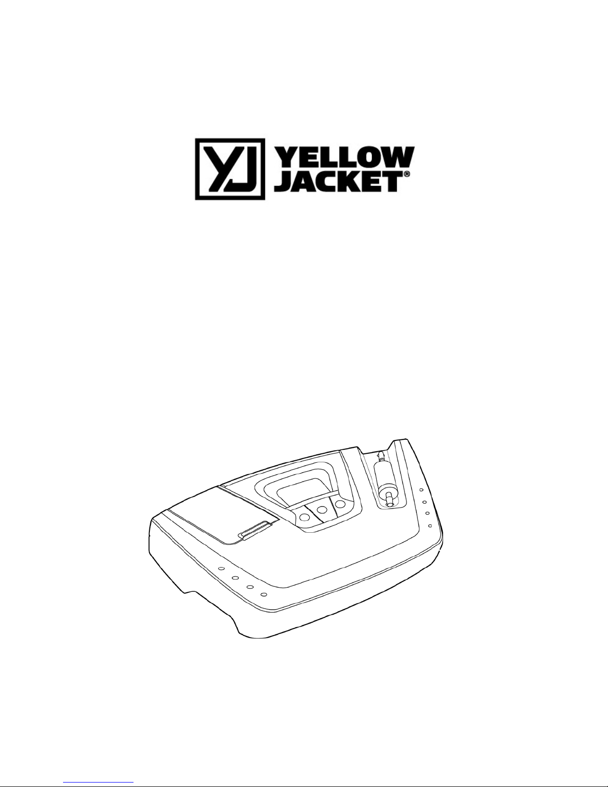
68945 and 68947
REFRIGERANT IDENTIFIER
OPERATION MANUAL
Page 2

Table of Contents
Safety and Warnings…………………………………………………………………………………………………………………………………………………4
1INTRODUCTION AND OVERVIEW.......................................... 6
1.1 GENERAL ............................................................. 6
1.2 FEATURES ............................................................ 7
1.3 YELLOW JACKET REFRIGERANT IDENTIFIER COMPONENTS ........................... 8
1.3.1 Base Unit ....................................................... 8
1.3.2 R134a Sample Hose ............................................... 8
1.3.3 R12 Sample Hose ................................................. 9
1.3.4 R134a Tank Adapter Fitting ...................................... 9
1.3.5 Vehicle Power Cable ............................................. 9
1.3.6 Control Panel .................................................. 10
1.3.7 Back Panel Connections ......................................... 10
1.3.8 Hard Shell Storage/Carrying Case ............................... 11
2 OPERATION ....................................................... 12
2.1 FIRST USE .......................................................... 12
2.1.1 Battery Installation (Optional) ................................ 12
2.2 TURNING ON THE UNIT .................................................. 13
2.3 CALIBRATION ......................................................... 13
2.4 VIEWING THE TEST RESULTS .............................................. 14
2.5 BLEND REFRIGERANTS ................................................... 15
2.6 PRINTING THE TEST RESULTS ............................................. 16
3 MAINTENANCE & TROUBLESHOOTING ................................... 17
3.1 SETTING THE ELEVATION ................................................. 17
3.2 SETTING THE LCD CONTRAST .............................................. 18
3.3 CHANGING THE SAMPLE FILTER ............................................. 19
3.4 CLEANING THE SAMPLE HOSES ............................................. 19
3.5 CHANGING THE PRINTER PAPER ............................................. 19
3.6 LOW BATTERY WARNING .................................................. 20
3.7 ERROR MESSAGES ...................................................... 21
Page 3

4 APPENDICES ....................................................... 22
4.1 SPARE PARTS LIST ..................................................... 22
4.2 APPENDIX B - SPECIFICATIONS ............................................ 22
Page 4
For Your Safety:
PLEASE READ THIS MANUAL IN ITS ENTIRETY BEFORE
ATTEMPTING INSTALLATION OR OPERATION! Attempting to
operate this refrigerant identifier without fully
understanding its features and functions may result
in unsafe conditions
• Always use protective eye wear and observe proper safety
procedures when working with pressurized gases.
Read and understand the entire manual BEFORE attempting to operate the instrument.
Identifier Warnings
• Refrigerant Blend Warning: As of January 2004, there are
twelve (12) EPA SNAP “acceptable for use” refrigerants that
are available and legal for use as R12 substitutes. This
refrigerant identifier will not identify any of the
substitutes as pure R12 or pure R134a. Each of the twelve
blends has been tested in the factory laboratory and it has
been confirmed that the substitutes will not “fool” the
instrument. Should one of the blends be encountered, the
instrument will fail the refrigerant and provide a readout of
analysis in terms of percentage by weight concentrations of
R12, R134a, R22 and hydrocarbons only. Due to cross
sensitivity issues of the blends on the sensing device, the
resultant reading will not be correct in the analyzed
concentrations. However, this refrigerant identifier will
never identify any of the blends as pure R12 or pure R134a.
• Sample Filter Warning: Replace the sample filter of the
instrument AS SOON AS RED SPOTS OR DISCOLORATION BEGIN TO
APPEAR ON THE OUTSIDE DIAMETER OF THE WHITE ELEMENT. Failure
to properly maintain and replace the sample filter will
result in severe damage.
• Sample Input Warning: The instrument requires connection of
the supplied sample hose to the LOW SIDE OR VAPOR port of
refrigerant storage cylinders or vehicle air conditioning
systems. DO NOT attempt to introduce liquid or samples
heavily laden with oil into the instrument. DO NOT connect
the sample hose to the HIGH SIDE or LIQUID port!
• Liquid or oil laden samples will cause severe damage to the
instrument that will not be covered under warranty repairs.
• Battery Charger Warning: When charging the battery with the
1000mA charger, the charger will become warm. If the charger
becomes hot, unplug the charger immediately! When charging
multiple battery packs, allow the charger to cool between
each battery.
4
Page 5

General Cautions
• Always inspect the sample hose before each use. Replace the
hose if it appears cracked, frayed, obstructed or fouled with
oil.
• ALWAYS turn the compressor or automobile engine off before
connecting the instrument to an air conditioning system.
• Always wear eye and skin protection when working with
refrigerants. Escaping refrigerant vapors will present a
freezing danger.
• To reduce the risk of electrical shock, do not disassemble
the instrument; do not use the instrument in wet or damp
areas.
• DO NOT direct refrigerant vapors venting from hoses towards
the skin.
• DO NOT disassemble the instrument. There are no serviceable
components internal to the instrument and disassembly will
void the warranty.
• ALWAYS place the Identifier on a flat and sturdy surface.
• DO NOT utilize any other hose other than those supplied with
the instrument. The use of other hose types will introduce
errors into the refrigerant analysis and instrument
calibration.
• ALWAYS verify that the refrigerant to be tested does not
contain or will not emit heavy loads of oil or liquid.
• NEVER admit any sample into the instrument at pressures in
excess of 300 psig.
• DO NOT utilize the coupler supplied on the service end of the
R134a Sample Hose for any application other than with the
instrument. The coupler supplied is a modified version that
does not contain a check valve and is not suitable for any
other refrigerant application.
• NEVER obstruct the air intake, sample exhaust or case vent
ports of the instrument during use.
5
Page 6

1. Introduction and Overview
1.1 General
Contamination of refrigerants either in storage cylinders or vehicle
air conditioning systems can lead to component corrosion, elevated
head pressures and system failures when utilized by unsuspecting
technicians. The ability of the technician to determine refrigerant
type and purity is severely hampered by the presence of air when
attempting to utilize temperature-pressure relations. The
development of various substitute refrigerants further complicates
the ability of a technician to identify refrigerant purity based
upon temperature-pressure relationships. The substitute refrigerant
blends can also introduce a flammability hazard to the technician
and the ultimate end user of the vehicle air conditioning system.
The YELLOW JACKET Refrigerant Identifier will provide a fast, easy
and accurate means to determine refrigerant purity in refrigerant
storage cylinders or directly in vehicle air conditioning systems.
The instrument utilizes non-dispersive infrared (NDIR) technology to
determine the weight concentrations of refrigerant types R12, R134a,
R22, as well as, hydrocarbons and air. Refrigerant purity is
automatically determined for refrigerants R12 and R134a by the
instrument to eliminate human error. Pure refrigerant is defined as
a refrigerant mixture that contains 98%, by weight, or greater of
either R12 or R134a.
The instrument is supplied complete with a R12 and R134a sample
hose, a R134a adapter fitting to permit sampling of ACME ported
cylinders, a 12 VDC power cord and all required plumbing housed
within a rugged, portable, storage case.
Sample gas is admitted into the instrument through the supplied
sample hose and presented to the sensing device. The instrument
provides the user with direct percent by weight concentrations of
R12, R134a, R22 and hydrocarbons. If the sample is determined to be
pure R134a, the instrument will provide a direct readout of the
weight percentage of air within the sample. Note that the
instrument does not consider air to be a contaminate since it can be
removed by most refrigerant recycling equipment. Since air is not
considered to be a contaminate, it is possible to read 100% R134a
plus 5% air. The instrument only considers the weights of the
refrigerant and contaminates in the total mixture for R134a as air
contamination in R12 systems causes only minor performance
degradation.
6
Page 7

The instrument interfaces with the user with an LCD graphic display,
status indicator lamps, push button communication switches and an
alarm horn. Alarm indications are provided to alert of instrument
fault conditions or contaminated refrigerant presence. Direct
percent by weight concentrations of the sample refrigerant is
provided on the display as well as user directions and prompts. An
optional on-board printer (Model RI-2004DXP) is available to print
on-the-spot customer confidence receipts.
The YELLOW JACKET Refrigerant Identifier will provide the
refrigerant technician with absolute knowledge of refrigerant
purity and protection against refrigerant contamination and
potential flammability.
1.2 Features
The YELLOW JACKET Refrigerant Identifier is the most advanced
instrument ever manufactured for determining the purity of gaseous
refrigerants for the automotive market.
Features Include:
• Advanced ergonomic design
• Fender friendly resting surface
• Large graphic display with on-screen instructions
• Ultra fast 60 second test time
• Blend-ID software to identify the presence of popular SNAP
Approved Blend Refrigerants
• Built in printer option for instant customer confidence
receipt
• Internal, rechargeable battery option for cordless operation
in any location
• Hard shell carry/storage case
7
Page 8
Components
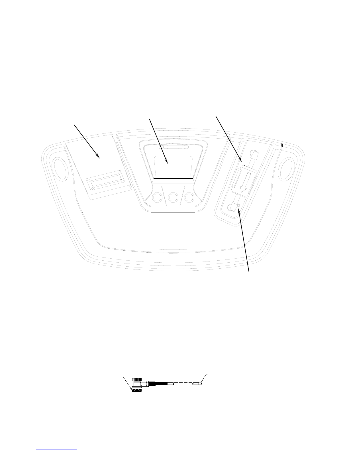
1.3.1 Base Unit
The base unit houses the Graphic Display, Infrared Bench, Electrical
Connections, and Optional Printer Module. These components require
no maintenance, therefore there are no serviceable components
internal to the instrument, and disassembly will void the warranty.
1.3.2 R134a Sample Hose
The 6-foot (1.8 meter) R134a Sample Hose is constructed of a nylon
inner tube and a polyurethane outer tube. The inner tube will
handle all of the refrigerant transfer and will provide containment
up to 300 psig. The outer tube will provide protection of the inner
tube from abrasion, nicking, cutting, etc. The hose is provided
with an instrument inlet port mating connector on one end and the
R134a Low Side Coupler on the service end.
Identifier End
Service End
R134a Low Side Coupler
Control Panel
Sample Filter
Printer Door
Air Intake Port
8
Page 9
1.3.3 R12 Sample Hose
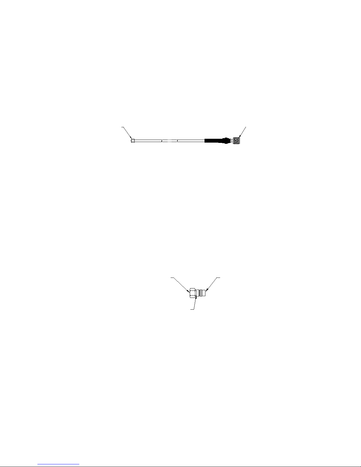
The 6-foot (1.8 meter) R12 Sample Hose is constructed of a nylon
inner tube and a polyurethane outer tube. The inner tube will
handle all of the refrigerant transfer and will provide containment
up to 300psig. The outer tube will provide protection of the inn er
tube from abrasion, nicking, cutting, etc. The hose is provided
with an instrument inlet port mating connector on one end and a ¼”
SAE female flare coupling nut on the service end.
1.3.4 R134a Tank Adapter Fitting
The R134a Tank Adapter Fitting will provide the user with an adapter
to allow connection of the R134a sample hose service end to a R13 4a
cylinder ACME port.
1.3.5 Vehicle Power Cable
The unit is powered from a vehicles 12VDC battery. The power cable
is a 6-foot cable that has an instrument mating connector on one end
and vehicle battery connection clips on the other end. This harness
is utilized to connect power from the vehicle battery to operate the
instrument. Note: The vehicle power cable can be used with the
optional battery pack installed in the unit. The vehicle power
cable will not charge the battery.
Service End
(1/4 SAE Flare Nut)
Identifier End
R134a Low Side Stub
(Fits into R134a Low Side
½” Acme Thread
(Threads onto Cylinder Stub)
O-Ring Seal
(Internal)
9
Page 10
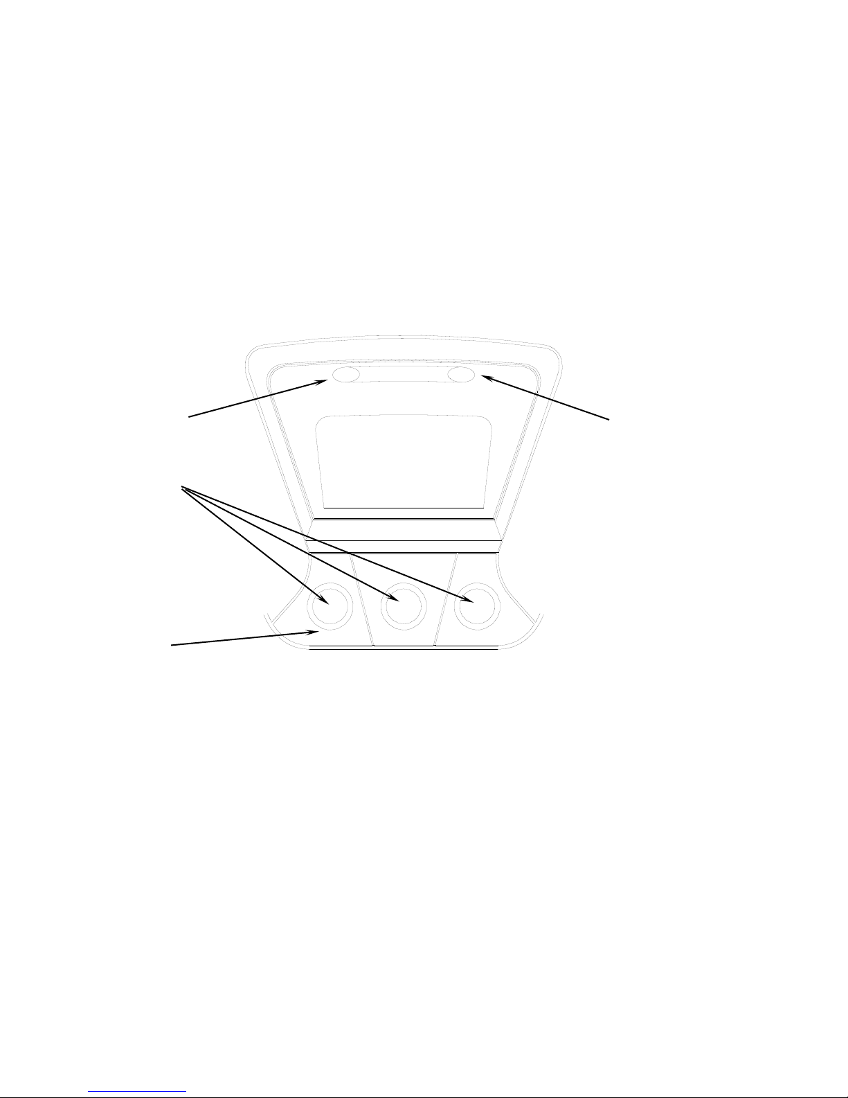
1.3.6 Control Panel
The Control Panel serves as the main user interface. The Control
Panel features three soft key buttons that change their function as
the instrument changes modes. The current function for each button
is displayed by the soft key label at the bottom of the graphic
display. Red and Green LED’s at the top of the Control Panel are
used for visual Pass/Fail indications.
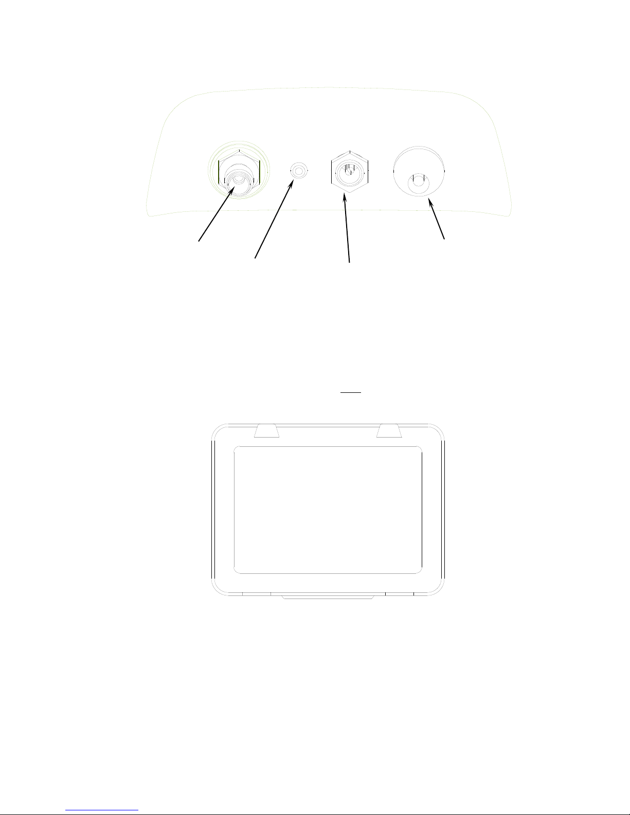
1.3.7 Back Panel Connections
The connections located on the back panel are illustrated below.
CAUTION:
The sample outlet port should never be obstructed.
Keep the sample outlet port free and clear at all times.
Green LED
Red LED
Soft Key
Buttons
Power
On/Off
Graphic
Display
7
10
Page 11
1.3.8 Hard Shell Storage/Carrying Case
The hard shell storage/carrying case is custom fit to the
refrigerant identifier. It provides rugged protection for the
instrument as well as convenient storage for all components. The
enclosure is general purpose and is not watertight.
Sample Inlet
Sample Outlet
Battery Charge Port
12VDC Power Input
(Battery Clips)
11
Page 12
2 OPERATION
2.1 First Use
2.1.1 Battery Installation (Optional)
The refrigerant identifier has, as an option, an internal
rechargeable battery. If your uit is equipped with the optional
rechargeable battery, you must first install and charge the battery
prior to use. NOTE: The refrigerant identifier can be operated
with or without the battery using the supplied battery clips. Refer
to Section 2.2 for instructions.
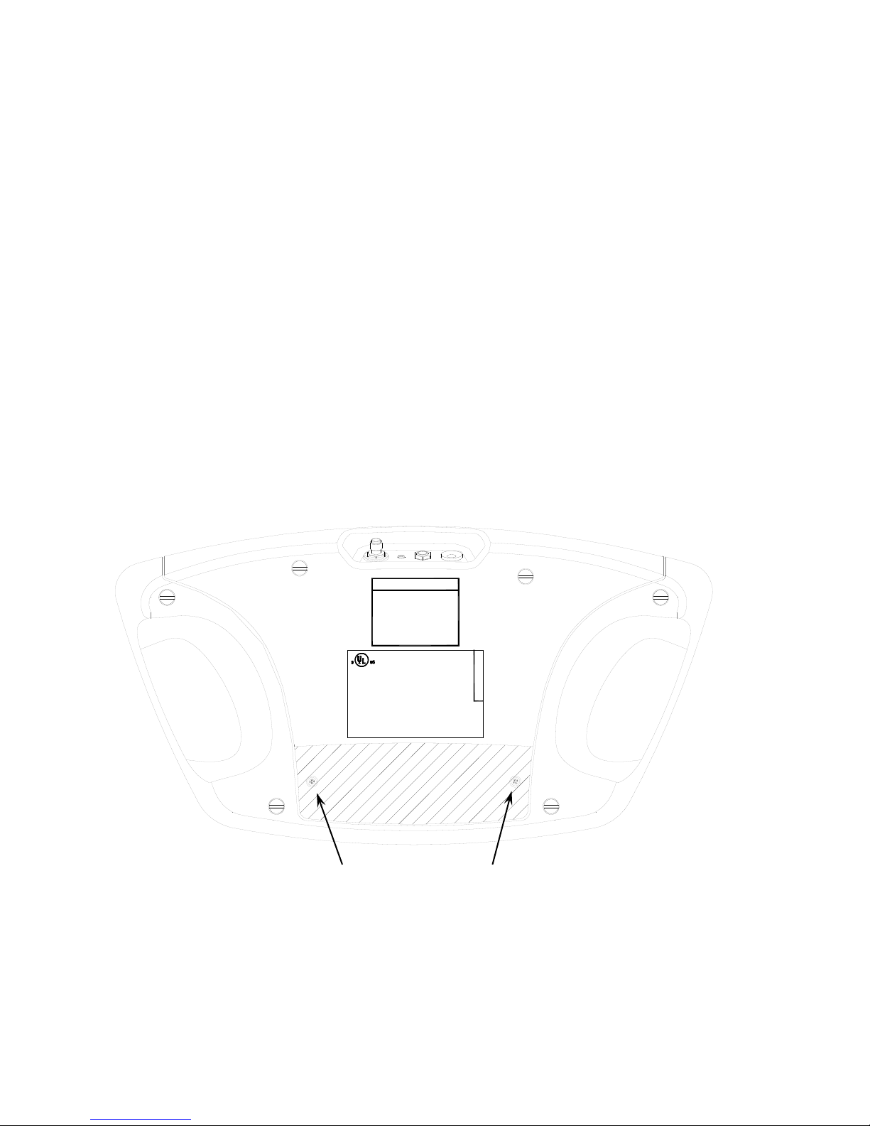
To install the optional battery, remove the battery cover from the
back of the unit by unscrewing the two Phillips head screws as shown
below.
OR OPENED CONTAINERS OF GASOLINE.
at least 18 inches above to flo or.
Use this equipment in location s with mechanical ventilation that
provides at l eat four air change s per hour or locate th e equipment
DATE CODE:
NEUTRONICS INC. MODEL No: UID
(610) 524-8800, www.NeutronicsInc .com
456 Creamery Way, Exton, PA, 19431 USA
WARNING-TO REDUCE THE RISK OF FIRE:
DO NOT USE THIS EQUIPMENT IN THE VICINITY OF SPILLED
LISTED 6P03
Design Pressure: 300 p sig
Refrigerant Type: R-12, R-134a
R
Miscellaneous Refrig erant Equipment
12 VDC, 1A; Design Pressure: 300 psig
CFC-12 (R-12) or HFC-134a (R-134a)
(R-134a).
For Accuracy, see Manual.
detect 2% or greater of air in HFC-R134a
to 98% purity. Also this equipment will
to Meet SAE J1771 to identify
Refrigerant Diagnostic Tool Design
Certified by Intertek Testing Services (ITS)
SAE J1771 CERTIF ICATION
Inside of the battery compartment, locate the male plug on the left
side. Slide the nylon strap around the battery. Insert the battery
module into the compartment aligning the female connector of the
battery module with the male plug in the battery compartment.
Replace the cover and snug the screws.
Battery Cover Screws
12
Page 13

Note: Charge the battery for a minimum of 4 hours with the supplied
charger prior to first use.
To remove the battery, simply tug gently on the nylon strap, being
sure to pull straight up, until the battery is dislodged.
2.2 Turning On the Unit
Connect the supplied vehicle power cable to the 12VDC power input
jack on the back of the unit. Connect the battery clips to the
vehicles 12VDC battery. (Note: If the optional battery module is
installed and charged, the vehicle power cable is not required.)
Press the left, soft key, power button and the splash screen shown
in Figure 1 will appear for approximately three seconds followed by
the elevation screen shown in Figure 2. See section 3.1 for details
on setting the elevation. Depressing the “DONE” button will bring
the refrigerant identifier to the Calibration screen as shown in
Figure 3.
ULTIMA ID
SOFTWARE VERSION
XXX XX.XXX
THE OPERATING
ELEVATION HAS
NOT BEEN SET
SELECT HELP ON
THE NEXT SCREEN
DONE
READY TO AIR CAL
1. DISCONNECT
HOSE FROM
VEHICLE
2. PRESS CAL TO
START
OFF HE LP CAL
2.3 Calibration
Each time the refrigerant identifier begins a new test cycle it must
first self calibrate. The calibration takes 30 seconds (Figure 4)
and brings fresh air into the unit via an internal pump. This fresh
air purges any excess refrigerant from the unit and ensures accurate
test results. Calibration requires that the hose be disconnected
from the vehicle or refrigerant cylinder. During calibration, the
screen shown in Figure 5 will appear reminding the user to change
the filter under certain conditions. For additional details on how
and when to change the filter, refer to Section 3, Maintenance and
Troubleshooting. The calibration of the unit will expire after
approximately five minutes of inactivity. If this occurs, the
screen shown in Figure 6 will b e displayed requiring the calibration
to be initiated again.
Figure 1
Figure 2
Figure 3
13
Page 14

CALIBRATING
THIS WILL ONLY
TAKE 30 SECONDS
- CALIBRATING NOTE
REPLACE FILTER
WHEN WHITE
ELEMENT BEGINS
TO SHOW RED
SPOTS ON OUTSIDE
DIAMETER
CALIBRATION TIME
HAS EXPIRED
DISCONNECT HOSE
FROM VEHICLE AND
PRESS CAL TO
RECALIBRATE
CAL
After calibrating, the unit will display the screen shown in Figure
7. Connect the hose to the vehicle, (for R134a open the valve) and
select the refrigerant type you wish to test. The Ultima ID will
display the screen shown in Figure 8. If you wish to change any of
the factory default settings, refer to section 3.
READY
1. CONNECT HOSE
OPEN VALVE
2. SELECT
REFRIGERANT
TO TEST
R12
HELP R134A
TESTING
RXXX SAMPLE
THIS WILL ONLY
TAKE 30 SECONDS
2.4 Viewing the Test Results
Upon completion of the test, the refrigerant identifier will display
a screen similar to that shown in Figure 9 or Figure 10.
PASS
R134
100.0%
AIR 2.8%
HELP MORE
FAIL
R134
95.0%
HELP MORE
Figure 4
Figure 5
Figure 6
Figure 7
Figure 8
Figure 9
Figure 10
14
Page 15

If the refrigerant tested is 98% pure or better, and the air content
is less than 10%, the “PASS” screen will display and the Green LED
will illuminate. Should the refrigerant be less than 98% pure or
the air content greater than 10%, the “FAIL” screen will display and
the Red LED will illuminate. In either case, selecting the “MORE”
button will display the details in Figure 11 for “PASS” and Figure
12 for “FAIL”.
RESULTS………PASS
R134 100.0%
R12 .0%
R22 .0%
HC .0%
AIR 2.8%
EXIT
PRINT
RESULTS………….FAIL
R134
95.0%
R12
5.0%
R22
.0%
HC
.0%
EXIT
PRINT
2.5 Blend Refrigerants
The refrigerant identifier includes the “Blend ID” feature for
determining the presence of EPA S.N.A.P approved blend refrigerants.
In the event that the refrigerant identifier determines that the
refrigerant in the system or cylinder is possibly a S.N.A.P. blend,
the results will display as follows in Figures 13, 14, and 15. Note
that pressing the additional “MORE” button on the screen in Figure
14 will take the user to the Blend Refrigerant screen shown in
Figure 15. Note: This screen will vary based on the test results.
FAIL
R12 92.7%
HELP MORE
RESULTS………….FAIL
R12 7.3%
R134 92.7%
R22 .0%
HC .0%
EXIT MORE PRINT
POSSIBLY ONE OF
THE FOLLOWING
BLEND
REFRIGERANTS
FREEZE 12
FREE ZONE OR
RB-276
DONE
Pressing the “DONE” button in Figure 15 will return the user to the
screen shown in Figure 14.
Figure 11
Figure 12
Figure 13
Figure 14
Figure 15
15
Page 16

2.6 Printing the Test Results
For units equipped with the optional built-in printer module, the
test results can be printed by selecting the “PRINT” button. After
the print is complete, carefully tear off the printout and the unit
will return to the previous screen. Additional printouts may be
made following the same procedure. To exit the test, press the
“EXIT” button. Figures 16, 17, 18 and 19, show sample printouts for
various test results.
Neutronics, Inc.
Refrigerant
Identifier
R134a = 100.0%
R12 = 0.0%
R22 = 0.0%
HC = 0.0%
AIR = 2.8%
Tested R134a….
Conclusion:
R134a: PASS<<<
______________
(Date)
______________
(Technician)
______________
______________
Neutronics, Inc.
Refrigerant
Identifier
R134a = 95.0%
R12 = 5.0%
R22 = 0.0%
HC = 0.0%
Tested R134a….
Conclusion:
R134a: FAIL<<<
______________
(Date)
______________
(Technician)
______________
______________
Neutronics, Inc.
Refrigerant
Identifier
R134a = 92.7%
R12 = 7.3%
R22 = 0.0%
HC = 0.0%
Tested R134a….
Conclusion:
R134a: FAIL<<<
Possible Blend:
FREEZE 12,
FREE ZONE, or
RB-276
______________
(Date)
______________
(Technician)
______________
______________
Neutronics, Inc.
Refrigerant
Identifier
R134a = 0.0%
R12 = 0.0%
R22 = 0.0%
HC = 0.0%
Tested R134a….
Conclusion:
R134a: FAIL<<<
EXCESSIVE AIR
______________
(Date)
______________
(Technician)
______________
______________
Figure 16
Figure 17
Figure 18
Figure 19
16
Page 17

3 MAINTENANCE & TROUBLESHOOTING
3.1 Setting the Elevation
During the initial power-up, the YELLOW JACKET Refrigerant
Identifier will indicate that the elevation has not been set. To
set the elevation, press the “Help” button on the “Ready to Air Cal”
screen as shown in Section 2.2, Figure 3. The screen will display
several options as shown in Figure 20. Pressing the “SET” button
will display the options in Figure 21.
TO CHANGE
SETTINGS OR
REPLACE PAPER
ROLL PRESS SET
FOR OTHER HELP
PRESS HELP
SET HELP DONE
TO FEED IN A
NEW PAPER ROLL
PRESS FEED
PRESS SET TO
ADJ LCD CONTRAST
OR ELEVATION
SET FEED DONE
Press the “SET” button shown in Figure 21 to display the screen
options shown in Figure 22. Pressing the “ELEV” button will take
you the elevation screen shown in Figure 23. Use the “UP” & “DOWN”
buttons to adjust the unit to the elevation in your area. Press the
“SAVE” button when finished to return to the help screen (Figure
20).
TO SET THE
ELEVATION PRESS
ELEV BUTTON
TO SET THE
LCD CONTRAST
PRESS CONT
ELEV CONT DONE
FEET
400
METERS
122
UP DOWN SAVE
Figure 20
Figure 21
Figure 22
Figure 23
17
Page 18

3.2 Setting the LCD Contrast
The YELLOW JACKET Refrigerant Identifier features an adjustable LCD
contrast for use in varying light conditions. To adjust the
contrast, press the “HELP” button on the “Ready to Air Cal” screen
as shown in Section 2.2, Figure 3. The screen will display several
options as shown in Figure 17. Pressing the “SET” button will
display the options in Figure 18.
TO CHANGE
SETTINGS OR
REPLACE PAPER
ROLL PRESS SET
FOR OTHER HELP
PRESS HELP
SET HELP DONE
TO FEED IN A
NEW PAPER ROLL
PRESS FEED
PRESS SET TO
ADJ LCD CONTRAST
OR ELEVATION
SET FEED DONE
Press the “SET” button shown in Figure 24 to display the screen
options shown in Figure 25. Pressing the “SET” button in Figure 25
will advance the display to Figure 26. Pressing the “CONT” button
will take you the contrast screen shown in Figure 27. Use the “UP”
& “DOWN” buttons to adjust the screen contrast for best viewing.
Press the “SAVE” button when finished to return to the help screen
(Figure 24).
TO SET THE
ELEVATION PRESS
ELEV BUTTON
TO SET THE
LCD CONTRAST
PRESS CONT
ELEV CONT DONE
ADJUST CONTRAST
FROM 0 TO 80
SETTING
045
UP DOWN SAVE
Figure 24
Figure 25
Figure 26
Figure 27
18
Page 19

3.3 Changing the Sample Filter
When inspecting the sample filter, look completely around the entire
outside diameter of the white filter element located inside of the
clear plastic housing. Look for red spots or the beginnings of
discoloration on the white outside diameter of the element. Do not
look into the round ends of the white element for red spots or
discoloration. The round ends of the filter may always appear red.
If red spots or discolorations are discovered, the sample filter
requires replacement to prevent the influx of particulate and oil
mists into the instrument.
Obtain a replacement filter. Remove the existing filter from the
retaining clip of the instrument by pulling straight up and out.
CAREFULLY remove the flexible, black rubber tubing connections from
both ends of the existing filter. DO NOT allow the tubes to slip
back into the internal portion of the case. Discard the existing
filter in an environmentally friendly manner.
Install the tube ends onto the barbs of the replacement filter,
taking note to align the flow arrow of the filter with the flow
arrow of the instrument top panel. CAREFULLY slide the tubing back
into the internal portion of the instrument and seat the new filter
into the retaining clip. Inspect the sample hoses for signs of o il
entrapment. Replacement of the sample filter usually requires
cleaning or replacement of the sample hoses.
3.4 Cleaning the Sample Hoses
Inspect the inside diameter of the inner tube for signs of oil build
up, dirt, obstructions, kinks, cuts, fraying, or any other signs of
wear. Oil contamination can be cleaned out of sample hoses as
directed below. Hoses that show signs of wear should be replaced
immediately to avoid dangers of rupture or bursting.
Remove the hose from the instrument and flush with iso propyl alcohol
until the oil is thoroughly cleansed from the inner tube.
Warning: Flush hoses away from sparks, open flames or other
ignition sources and in an area that is well ventilated.
Dry the hose by blowing clean, dry nitrogen or shop ai r through the
inner hose or by allowing the hose to air-dry for several hours.
Take care to not dry the hose with shop air that is lubricated.
When the hose is completely dry, re-inspect the hose for signs of
wear, as described above, and replace if wear is evident.
3.5 Changing the Printer Paper
The YELLOW JACKET Refrigerant Identifiers that are equipped with onboard printers use an inexpensive thermal paper for printing. The
paper roll should be changed when a red stripe appears on the left
side of the printout.
19
Page 20
To change the paper roll, press the “HELP” button on the “Ready to
Air Cal” screen as shown in Section 2.2, Figure 3. The screen will
display several options as shown in Figure 28. Press the “SET”
button to advance to the screen shown in Figure 29 and then press
the “FEED” button.
TO CHANGE
SETTINGS OR
REPLACE PAPER
ROLL PRESS SET
FOR OTHER HELP
PRESS HELP
SET HELP DONE
TO FEED IN A
NEW PAPER ROLL
PRESS FEED
PRESS SET TO
ADJ LCD CONTRAST
OR ELEVATION
SET FEED DONE
TO LOAD PAPER
1. PRESS FEED
2. INSERT PAPER
3. PRESS STOP
4. PRESS TEST TO
TEST AND EXIT
FEED STOP TEST
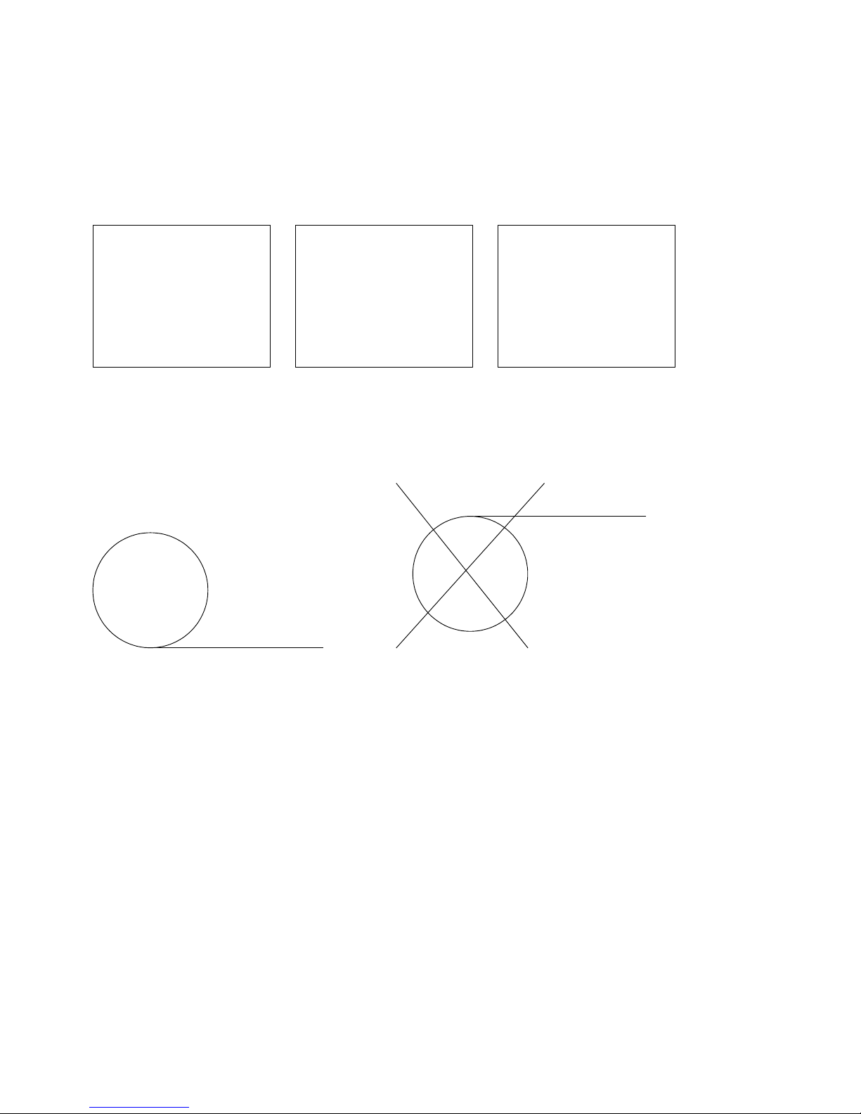
Open the printer door and remove the old roll by tearing the paper
as it enters the printer then pressing the “FEED” button shown in
Figure 30 until the old roll exits the printer completely. Insert
the new paper roll from the underside as shown below:
Press the “FEED” button shown in Figure 30 to automatically advance
the paper through the printer. When the paper appears on the top of
the printer, press the “STOP button. Press the “TEST” button to
print a test message and verify that the paper is installed
properly. Slide the paper through the slot in the pri nter door and
close the door.
3.6 Low Battery Warning
For units equipped with the optional rechargeable battery, a “Low
Battery Warning” will appear when the battery is nearly exhausted.
Several tests may be run after the initial warning however, it is
strongly recommended that the unit be recharged or the external
battery clips be used.
Figure 28
Figure 29
Figure 30
Correct
Incorrect
20
Page 21

3.7 Error Messages
In the unlikely event that an “Error” message is displayed on the
screen, power off the unit, take it to a location outside of the
shop environment where fresh air is available and turn the unit back
on. If the “Error” message reappears, contact our service
department for assistance.
Ritchie Engineering Co., Inc.
10950 Hampshire Avenue South
Bloomington, MN 55438
Ph: 800-769-8370 or 952-943-1300
21
Page 22
4 APPENDICES
4.1 Spare Parts List
PART NUMBER
DESCRIPTION
68948
Optional internal rechargeable battery kit with
battery and 110V charger
68949
Optional 110/220V power adapter
68950
Thermal printer paper – 1 roll
68977
In line identifier replacement filter
68978
R-12 replacement hose
68979
R-134a replacement hose
68994
Replacement flow restrictor hose (3 pak)
4.2 Appendix B - Specifications
SAMPLE PARAMETERS:
Vapor only, oil-
free, 300 psig (2 MPa)
Maximum
DETECTED COMPOUNDS:
R12, R134a, R22, Hydrocarbons, Air
SENSOR TECHNOLOGY:
Non-Dispersive Infrared (NDIR)
REFRIGERANT SAMPLE
SIZE:
0.3 ounces (8.5 grams) per sample
POWER:
9 – 15 VDC, 2 Amps Maximum
OPERATIONAL
TEMPERATURE:
40-130oF
SAE J1771
If the refrigerant being tested is
identified as contaminated, any visual
percentages displayed of CFC-12 (R-12) or
HFC-134a (R134a) outside the design
certified value is informational and may
not be accurate.
This instrument has not been design
certified for contaminate detection of
R124 or R142b.
22
 Loading...