

Page 1

MyPBX U100/U200
Administrator Guide
Version 15.19.0.23
Yeastar Information Technology Co. Ltd
Page 2

MyPBX U100/U200 Administrator Guide
2/195
Table of Contents
1. Introduction ........................................................................................ 5
1.1 Features .................................................................................................................. 5
1.2 Hardware Specifications .......................................................................................... 7
1.2.1 Exterior Appearance ..................................................................................................................... 7
2. System Setup ..................................................................................... 8
2.1 Connection Drawing ................................................................................................ 8
2.2 Connecting Ethernet Line ........................................................................................ 8
2.3 Supplying Power...................................................................................................... 9
3 Administrator Login ............................................................................ 10
4 Status ............................................................................................... 13
4.1 Line status ............................................................................................................. 13
4.1.1 Extension Status ......................................................................................................................... 13
4.1.2 Trunk Status ................................................................................................................................ 14
4.2 System Status ........................................................................................................ 15
4.2.1 System Info ................................................................................................................................. 15
4.2.2 Network Status ........................................................................................................................... 15
5 System ............................................................................................. 16
5.1 Network Preferences ............................................................................................. 16
5.1.1 LAN Settings ............................................................................................................................... 16
5.1.2 WAN Settings .............................................................................................................................. 18
5.1.3 DHCP Server ............................................................................................................................... 19
5.1.4 VLAN Settings ............................................................................................................................. 19
5.1.5 VPN Settings ............................................................................................................................... 22
5.1.6 DDNS Settings ............................................................................................................................. 23
5.1.7 Static Route ................................................................................................................................ 23
5.2 Security Settings .................................................................................................... 24
5.2.1 Security Center ........................................................................................................................... 25
5.2.2 Firewall Rules .............................................................................................................................. 26
5.2.3 IP Blacklist .................................................................................................................................. 28
5.2.4 AMI Settings ............................................................................................................................... 29
5.2.5 Database Grant ........................................................................................................................... 30
5.2.6 Alert Settings .............................................................................................................................. 31
5.3 LDAP ..................................................................................................................... 34
5.3.1 LDAP Server ................................................................................................................................ 34
5.4 Storage Management ............................................................................................ 36
5.4.1 USB Device ................................................................................................................................. 36
5.4.2 External Storage .......................................................................................................................... 36
5.5 System Preference................................................................................................. 39
5.5.1 Password Settings ....................................................................................................................... 39
5.5.2 Date and Time ............................................................................................................................ 40
5.5.3 Firmware Update ........................................................................................................................ 41
5.5.4 Backup and Restore .................................................................................................................... 42
Page 3

MyPBX U100/U200 Administrator Guide
3/195
5.5.5 Reset and Reboot ........................................................................................................................ 43
5.5.6 Hot Standby ................................................................................................................................ 43
6 PBX .................................................................................................. 46
6.1 Extensions ............................................................................................................. 46
6.1.1 FXS/VoIP Extensions .................................................................................................................... 46
6.1.2 Phone Provisioning ..................................................................................................................... 57
6.2 Trunks ................................................................................................................... 65
6.2.1 Physical Trunk ............................................................................................................................. 65
6.2.2 VoIP Trunk .................................................................................................................................. 73
6.3 Outbound Call Control ........................................................................................... 82
6.3.1 Outbound Routes ........................................................................................................................ 82
6.3.2 Speed Dial Settings...................................................................................................................... 85
6.4 Inbound Call Control ............................................................................................. 86
6.4.1 IVR ............................................................................................................................................. 86
6.4.2 Ring Groups ................................................................................................................................ 89
6.4.3 Queues ....................................................................................................................................... 91
6.4.4 Conferences ................................................................................................................................ 95
6.4.5 Inbound Routes .......................................................................................................................... 96
6.5 Audio Settings ..................................................................................................... 102
6.5.1 Custom Prompts ....................................................................................................................... 102
6.5.2 Music on Hold Prompts ............................................................................................................. 103
6.5.3 System Prompts Settings ........................................................................................................... 104
6.6 Basic Settings ...................................................................................................... 105
6.6.1 General Preferences .................................................................................................................. 105
6.6.2 Business Hours.......................................................................................................................... 108
6.6.3 Feature Codes ........................................................................................................................... 109
6.6.4 Voicemail Settings ..................................................................................................................... 112
6.7 Advanced Settings ............................................................................................... 116
6.7.1 SIP Settings ............................................................................................................................... 116
6.7.2 IAX Settings............................................................................................................................... 123
6.7.3 Blacklist .................................................................................................................................... 124
6.7.4 Callback Settings ....................................................................................................................... 125
6.7.5 DNIS Settings ............................................................................................................................ 127
6.7.6 DISA ......................................................................................................................................... 127
6.7.5 PIN User Settings ...................................................................................................................... 129
6.7.8 PIN Settings .............................................................................................................................. 130
6.7.9 Paging Groups ........................................................................................................................... 131
6.7.9 SMS Settings ............................................................................................................................. 133
6.7.10 Certificates ............................................................................................................................. 135
7 Reports ........................................................................................... 136
7.1 Call Logs .............................................................................................................. 136
7.2 System Logs ........................................................................................................ 136
8 Addons ............................................................................................ 137
8.1 Call Recording ..................................................................................................... 138
Page 4

MyPBX U100/U200 Administrator Guide
4/195
8.2 MyPBX Client....................................................................................................... 138
8.3 Billing System ...................................................................................................... 138
8.4 Hotel Module ...................................................................................................... 139
9 Logout ............................................................................................ 139
10. Use MyPBX .................................................................................... 140
10.1 Make outbound calls ......................................................................................... 140
Sample Routing via VoIP Trunk ........................................................................................................... 141
10.2 Incoming call ..................................................................................................... 143
Sample Routing to an IVR................................................................................................................... 143
APPENDIX A FAQ ................................................................................. 145
APPENDIX B How to Configure Externa l Sto r a g e ...................................... 145
APPENDIX C How to Configure NAT Setting............................................. 147
APPENDIX D How to Use Auto Provision ................................................. 149
APPENDIX E How Do I Configure Distinctive Ring Tones ........................... 153
APPEND IX F How to Us e Email to SMS ................................................... 155
APPENDIX G How to Use DID ................................................................ 156
APPENDIX H How to Use BLF Key to Choose the PSTN line........................ 160
APPENDIX I MyPBX Security Configuration Guide..................................... 162
APPEND IX J How to Se t Up Auto Recordin g ............................................. 177
APPENDIX K How to use LDAP............................................................... 193
Page 5

MyPBX U100/U200 Administrator Guide
5/195
1. Introduct ion
MyPBX —IP-PBX for Medium Businesses/Home Office
New products MyPBX U100&U200 is a standalone em bedded hybrid PBX for
medium businesses and remote branch offices of larger organizations (1-200
users per site). MyPBX U100&U200 also offers a hybrid solution (a combination
of VoIP applications using PSTN/BRI/GSM/UMTS/FXS equipment) alternative
for enterprises who are not yet ready to migrate to a complete VoIP solution.
1.1 Features
● Addons, including recording /MyPBX
client/Billing/Hotel
● Follow me
● Alert ● HTTPS
● Audio In/Out
● Integrated built-in packet capture tools
● Auto-provision
● Interactive Voice Response (IVR)
● Blacklist
● Intercom/Zone Intercom
● BLF Support
● L2TP
● Blind Transfer ● LDAP
● Call Back ● Mobility Extension
● Call Detail Records (CDR) ● Multiple administrators
● Call Forward ● Music On Hold
● Call Parking ● Music On Transfer
● Call Pickup ● OpenVPN
● Call Recording ● Paging/Zone Paging
● Call Routing
● PIN Users
● Call transfer
● PPPoE
● Call Transfer
● QoS
● Call Waiting ● Queue
● Caller ID ● Ring Group
● Conference ● Route by Caller ID
● Database Grant ● Security Center
● DDNS ● Skype Integration (Skype Connect)
● Define Office Time ● Speed Dial
● Dial by Name ● Spy functions
● DIDs
● Static Route
● Direct Inward System Access(DISA)
● T. 3 8
● Distinctive Ringtone
● Three-way Calling
● Do Not Disturb(DND) ● VLAN
● External Storage ● Voicemail
● Firewalls ● WAN
Page 6

MyPBX U100/U200 Administrator Guide
6/195
URL of U100: http://www.yeastar.com/products/MyPBX-U100.asp
URL of U200: http://www.yeastar.com/Products/MyPBX-U200.asp
Page 7
MyPBX U100/U200 Administrator Guide
7/195
1.2 Hardware Specifications
1.2.1 Exterior Appearance
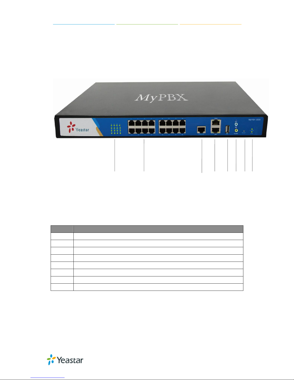
Front Panel
Figure 1-1 MyPBX U100&U200 Front Panel
No.
Indication
①
16 Green LEDs
②
16 RJ11 ports
③
Console p ort ( RJ45)
④
WAN/LAN port
⑤
USB 2.0 port
⑥
Audio in/out
⑦
Reset Button
⑧
Power and Run ind icator
①
② ③ ④ ⑤ ⑥ ⑦ ⑧
Page 8

MyPBX U100/U200 Administrator Guide
8/195
2. System Setup
2.1 Conn ec tion Dra w ing
Figure 2-1
2.2 Connec t ing Ether net Line
MyPBX provides two 10/100M Ethernet ports with RJ45 interface and LED
indicator. Plug Ethernet line into MyPBX’s Ethernet port, and then connect the
other end of the Ethernet line with a hub, switch, router, LAN or WAN. Once
connected, chec k the status of t he LED indicator. A yellow LED indicates the port
is in the connectio n process, and a green LED indicates the port is properly
connected.
Page 9

MyPBX U100/U200 Administrator Guide
9/195
2.3 Supp lying Power
Please follow the steps below to connect the MyPBX unit to a power outlet:
1. Connect the small end of the power cable to the power inpu t port on the
MyPBX back panel, and plug the other end of the cable into a 100V~240V AC
power outlet.
2. Check the Power LED on the front panel. A solid green LED indicates that
power is being supplied correctly.
Page 10

MyPBX U100/U200 Administrator Guide
10/195
3 Administrator Login
From your web b rows er, input the IP address of the MyPBX server.
If this is the first time you are configuring MyPBX, please use the default
settings as below (your PC should be in the same local network with MyPBX):
IP Address: http://192.168.5.150
Username: admin
Password: password
In this example, the IP ad d ress is 192.168.5.149
Figure 3-1
This is the welcome page of MyPBX U100&U200 after successful login.
Figure 3-2
You can also login via HTTPS protocol
Page 11

MyPBX U100/U200 Administrator Guide
11/195
Like https://192.168.5.147, you will see a pro mpt that is a certificate problem.
Click “Continue to …”, then you can login after entering user and
password .HTTPS is HTTP over SSL, and it is safer than HTTP .
Figure 3-3
Note:
MyPBX firmware upgrade follow-up
· Reboot the device twice to make the new firmware take effect
· Clean the cache and cookies of the browser before login.
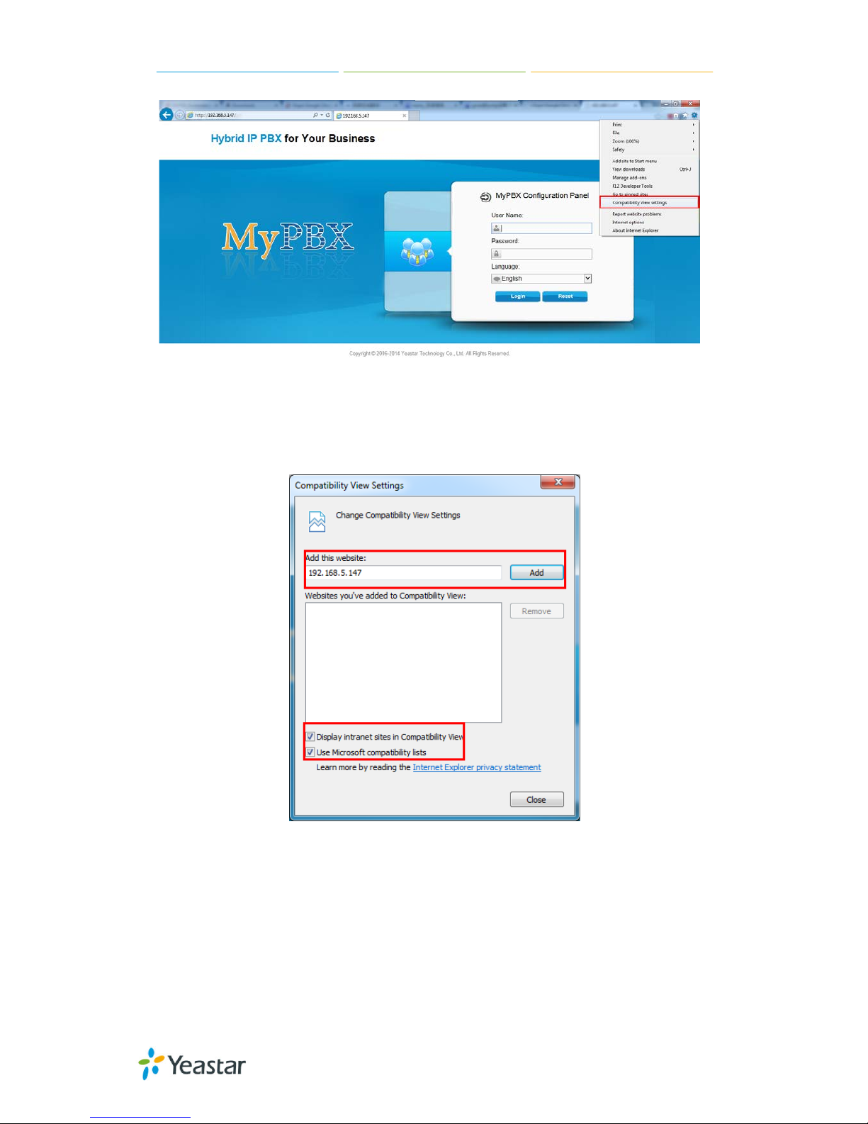
· There is a compatibility issue with IE11. Configure IE11 browser "Compatibility
View Settings", add MyPBX IP address, and check "Display Intranet sit es i n
Compatibility View" and "Use Microsoft compatibility lists".
See the following picture. MyPBX IP is 192.168.5.147 in this example.
Page 12
MyPBX U100/U200 Administrator Guide
12/195
Figure 3-4
Figure 3-5
Page 13

MyPBX U100/U200 Administrator Guide
13/195
4 Status
Click to start to check the statu s of MyP BX U3 00, where we can check
the status of extensions, trunks, network a nd sy st e m information.
4.1 Line status
In this page, we can che ck t he st atus of extensions and trunks
4.1.1 Extension Status
Figure 4-1
MyPBX Status Description:
Extensions:
1) : Extension is unavailable
2) : Extension is idle
3) : Extension is ringin g
4) : Extension is busy
5) : Extension is on hold
Page 14

MyPBX U100/U200 Administrator Guide
14/195
4.1.2 Trunk Sta tu s
Figure 4-2
Trunks:
VOIP Trunk:
Status
Unregistered: Trunk registration failed.
Registered: Successful reg i st ra tion, trunk is re ady for use.
Request Send: Registering.
Waiting: Waiting for authent ication.
Service Provider:
Status
OK: Successful registrat i on, t run k i s re a dy for use.
Unreachable: The trunk is unrea chable.
Failed: Trunk registration failed.
FXO Trunk:
Status
Idle: The port is idle.
Busy: The port is in use.
Disconnected: The port hasn’t connected to the PSTN line.
More detail message, please refer to the LED indication of front panel.
GSM/UMTS Trunk:
Status
Idle: The port is idle.
Busy: The port is in use.
Signal
: No signal.
: Poor.
: Average.
: Good.
: Excellent.
BRI Trunk:
Page 15

MyPBX U100/U200 Administrator Guide
15/195
Status
Ok: The ports connect correctl y.
Disconnected: The port hasn’t connected to the BRI line
4.2 Sys tem Status
In this pag e, we can check the status of M yPBX system, including the hardware,
firmware v ersion and t he ne t w ork st a t us of LAN a nd WAN ports.
4.2.1 System Info
In this page, we can check the hardware/firmware version, or the disk usage of
MyPBX.
Figure 4-3
4.2.2 Network Status
In this page, the IP address of L AN and WAN port will appear. If O penV PN is
configured well, they will be displayed here too.
Page 16

MyPBX U100/U200 Administrator Guide
16/195
Figure 4-4
5 System
Click to access.
In this page, we can configure the network settings, firewall settings, storage
management and some other preferences like firmware update and hot
standby.
5.1 Network Preferences
5.1.1 LAN Settings
Page 17

MyPBX U100/U200 Administrator Guide
17/195
Figure 5-1
·DHCP
If this option is set, MyPBX will use DHCP to get an available IP address from
your local ne t work. Not recommended as without t he rig ht IP address you
cannot access MyPBX.
·Enable SSH
This is the adv ance way to a ccess the device, you can use the p utty softwa re to
access the device. In the SSH access, you can do more advanced setting and
debug, it’s disabled by default.
·Port: the default is 8022; you change it to another one
·Enable FTP
Users will be able to log in MyPBX via FTP if FTP is enabled. You can access FTP
resource on MyPBX via Windows explorer or web browser.
FTP default user: root, password: ys123456
·Port: the def ault is 21; you change it to another one.
·Hostname
Set the host name for MyPBX.
·IP Address
Set the IP Address for MyPBX.
Configuring a static IP address for MyPBX is recommended.
·Subnet Mask
Set the subnet mask for MyPBX.
·Gateway
Set the gateway for MyPBX.
·Primary DNS
Set the primary DNS for MyPBX.
·Secondary DNS
Set the secondary DNS for MyPBX.
·IP Address2
Set the second IP Address for MyPBX.
·Subnet Mask2
Page 18

MyPBX U100/U200 Administrator Guide
18/195
Set the second subnet mask for MyPBX.
5.1.2 WAN Settings
Figure 5-2
It supports three connection types: DHCP (obta i n a n I P a ut oma t i ca l ly ), PPPoE,
Static IP Address.
Note:
1. WAN port is disabled by default
2. WAN port cannot be used as a router to route the internet packages from
WAN port to LAN port.
·DHCP
If your ISP says that you are connecti ng through DHCP or a dynamic I P address
from your IS P, p e rf orm t he s e st e p s :
Step1: Select DHCP as the WAN Connection Type.
Step2: Click Save button to save the settings.
Step3: Reboot the device.
Step4: Check the WAN’s Status (Status Network status).
·Static IP Address
If your ISP says that you are connecting through a static or fixed IP address
from your IS P, p e rf orm t he s e st e p s :
Step1: Select Static IP Address as the WAN Connec t ion Type.
Step2: Enter the IP Address.
Step3: Enter the Subnet Mask.
Step4: Enter the Gateway Address.
Step5: Enter the Primary DNS and Secondary DNS.
Step6: Click the Save button to save the settings.
Step7: Reboot the device.
Page 19

MyPBX U100/U200 Administrator Guide
19/195
Step8: Check the WAN’s Status (Status Network status).
·PPPoE
If your DSL provider says that you are connecting through PPPoE or if you
normally enter a user name and password to access the Internet, perform these
steps:
Step1: Select PPPoE as the WAN Connection Typ e .
Step2: Enter the User Name.
Step3: Enter the Password.
Step4: Click the Save button to save the settings.
Step5: Reboot the device.
Step6: Check the WAN’s Status (Status Network status)
5.1.3 DHCP Server
Dynamic Host Conf iguration Proto col (DHC P) is a network p rotocol that e nables
a server to automatic ally assign an IP address to a co mputer from a de fined
range of numbe rs (i .e ., a scope) configured for a given ne t work. You can set a
local network NTP server for MyPBX here too
Note: MyPBX U100&U200 can be working as a DHCP server, but cannot be
regarded as a router.
Figure 5-3
5.1.4 VLA N Settings
A VLAN (Virtual LAN) is a logical local area network (or LAN) that extends
Page 20

MyPBX U100/U200 Administrator Guide
20/195
beyond a single traditional LAN to a group of LAN segments, given specific
configurations.
Note:
MyPBX U100&U200 is not the VLAN server, a 3-layer switch is still needed,
please conf ig ure t he V LAN information t he re first, then inp ut the details in
MyPBX, so that the packages via MyPBX will be added the VLAN label before
sending to that switch.
Figure 5-4
1) VLAN Over LAN
·NO.1
Click the NO.1 you can edit the first VLAN over LAN.
·VLAN Number
.The VLAN Number is a unique value you assign to each VLAN on a single device.
·VLAN IP Address
Set the IP Address for MyPBX VLAN over LAN.
·VLAN Subnet Mask
Set the Subnet Mask for MyPBX VLAN over LAN.
·Default Gateway
Set the Default Gateway for MyPBX VLAN over LAN
·NO.2
Click the NO.2 you can edit the first VLAN over LAN.
·VLAN Number
Page 21

MyPBX U100/U200 Administrator Guide
21/195
.The VLAN Number is a unique value you assign to each VLAN on a single device.
·VLAN IP Address
Set the IP Address for MyPBX VLAN over LAN.
·VLAN Subnet Mask
Set the Subnet Mask for MyPBX VLAN over LAN.
·Default Gateway
Set the Default Gateway for MyPBX VLAN over LAN.
2) VLAN Over Wan
·NO.1
Click the NO.1 you can edit the first VLAN over WAN.
·VLAN Number
.The VLAN Number is a unique value you assign to each VLAN on a single device.
·VLAN IP Address
Set the IP Address for MyPBX VLAN over WAN.
·VLAN Subnet Mask
Set the Subnet Mask for MyPBX VLAN over WAN.
·Default Gateway
Set the Default Gateway for MyPBX VLAN over WAN.
·NO.2
Click the NO.2 you can edit the first VLAN over WAN.
·VLAN Number
.The VLAN Number is a unique value you assign to each VLAN on a single device.
·VLAN IP Address
Set the IP Address for MyPBX VLAN over WAN.
·VLAN Subnet Mask
Set the Subnet Mask for MyPBX VLAN over WAN.
·Default Gateway
Set the Default Gateway for MyPBX VLAN over WAN.
Page 22

MyPBX U100/U200 Administrator Guide
22/195
5.1.5 VPN Settings
A virtual private network (VPN) is a method of computer networking—typically
using the public internet—that allows users to privately share information
between remote locations, or between a remote location and a business home
network. A VPN can provide secure information transport by authenticating
users, and encrypting data to prevent unauthorized persons from reading the
information transmitted. The VPN can be used to send any kind of network
traff ic se curely. MyPBX supports OpenVPN, IPSec and L2TP.
Figure 5-5
·Enable OpenVPN
·Import VPN Profile
Import configuration file of OpenVPN. Don't config ure “user” and “group” in the
“config” file.
·Enable IPSec
·Import VPN Profile
Import configuration file of IPSec. There can be only one “lan” in the “conf” file.
·Enable L2TP
·Import VPN Profile
Import configuration file of L2TP. There can be only one “conn” in t he “conf” file.
Note: for more details about above VPN settings, please contact o ur technical
support.
Page 23

MyPBX U100/U200 Administrator Guide
23/195
5.1.6 DDNS S ettings
DDNS (Dynamic DNS) is a me t hod/p rotocol/network service that provides the
capability for a net worked d e vice , such a s a router or comput e r syst em using
the Internet Protocol Suite, to notify a Domain Name System (DNS) name
server to change, in real t ime , t he active DNS configuration of its conf igured
hostnames, addresse s o r othe r inf or ma t ion.
Figure 5-6
·Enable DDNS
·DDNS Server
Select the DDNS server you sign up for service.
·User Name
User name the DDNS server provides you.
·Password
User account’ s p a ssword.
·Host Name
Note: DDNS allows you to access your networ k using domain na mes instea d of
IP address. The service manages changing IP address and updates your domain
information dynamically. You must sign up for service through dyndns.org,
freedns.afraid.org, www.no-ip.com, www.zoneedit.com
5.1.7 Static Route
MyPBX will have more than one internet connect ion in some situations but it has
only one default gateway. You will need to set some Static Route for MyPBX to
force it goes out t hroug h d i f f e re nt g ateway when access to different internet.
The default gateway priority of MyPBX from high to low is OpenVPNWAN
portLAN port.
Page 24

MyPBX U100/U200 Administrator Guide
24/195
Figure 5-7
1) Route table
The current rout e rule s of M yPBX
·Destination
The destination network to be accessed to by MyPBX
·Subnet Mask
Specify the destination network portion.
·Gateway
Define which gateway MyPBX will go through when access to the destination
network.
·Metric
The cost of a route is calcula ted by using what are called routing metric. Routing
metrics are assigned to routes by routing protocols to provide measurable
statistic w hic h ca n b e use d to judge how useful (how low cost) a route i s.
·Interface
Define which int e rne t p ort t o g o throug h.
2) Static Route Rules
Y ou ca n add new static route rules here.
5.2 Security Settings
Firewalls are used to prevent unauthorized Internet users from accessing
private networks connec ted to the Inter n et, especially intranets. All messages
entering or lea ving the i ntrane t pass through t he firewa ll, which exa mines each
message and b locks t hose that do not meet the specified security criteria.
Page 25

MyPBX U100/U200 Administrator Guide
25/195
5.2.1 Security Center
Y ou can check MyPBX secu rity configura tion in “Security Center” page. And also,
you can enter the relevant security settings page rapidly.
Firewall:
Figure 5-8
In the “Firewall” t ab , you ca n check f ire wall conf igur at ion and ale rt set ting s. By
clicking the re le vant but t on, y ou ca n e nt e r t he conf i g uration pa g e d ire ct l y.
Service:
Figure 5-9 Security
In “Service” tab, you can check AMI/SSH/TFTP status. For AMI/SSH, you can
enter the according page by cli ck i n g th e button in “Setting” colum n. For TF TP,
you can directly disable or enable it.
Port:
Figure 5-10
Page 26

MyPBX U100/U200 Administrator Guide
26/195
In “Port” tab, you can check SIP port and HTTP port. You can also enter the
relevant page by clicki ng t he b utton in “Setting” column.
5.2.2 Firewall Rules
Figure 5-11
1) General Settings
·Enable Firewall
Enable the firewall to protect the device.
·Disable Ping
Enable this item; net ping from remote hosts will be dropped.
·Drop All
When you enable “Drop All” feature, system will drop all packets or connection
from other hosts if there are no other rules defined. To avoid locking the devices,
at least one “TCP” accept common rule must be created for por t u sed for SS H
access, port used for HTT P acce ss a nd p ort sued for CGI access.
2) Common Rules
There is no default rule; you can create them as required.
Page 27

MyPBX U100/U200 Administrator Guide
27/195
Figure 5-12
·Name
A name for this rule, e.g. “HTTP”.
·Description
Simple descript ion for this rule. E.g. Accept the sp ecific host to access the web
interface for configuration.
·Protocol
The protocols for th is rul e .
·Port
Initial p ort should be on the left a nd end p ort should b e on t he rig ht .
The end port must be equal to or greater than start port.
·IP
The IP address f or this rule. The f ormat of I P addre ss is: I P/mask
E.g. 192.168.5.100/255.255.25 5.255 for IP 192.168.5.100
E.g.216.207.245.47/255.255.255.255 for IP 216.207.2 45.47
E.g.192.168.5.0/255.255.255.0 f or IP from 192.168.5.0 t o 192.168.5.255.
·MAC Address
The format of MAC Address is XX:XX:XX:XX:XX:XX, X means 0~9 or A~F in hex,
the A~F are not case sensitive.
Note: The MAC address will be changed when it’s a remote device, so it will
not be working to filter using MAC for remote devices.
·Action
Accept: Accept t he a cce ss f rom remote hosts.
Drop: Drop the access from remote h osts.
Ignore: Ignore the access.
Page 28
MyPBX U100/U200 Administrator Guide
28/195
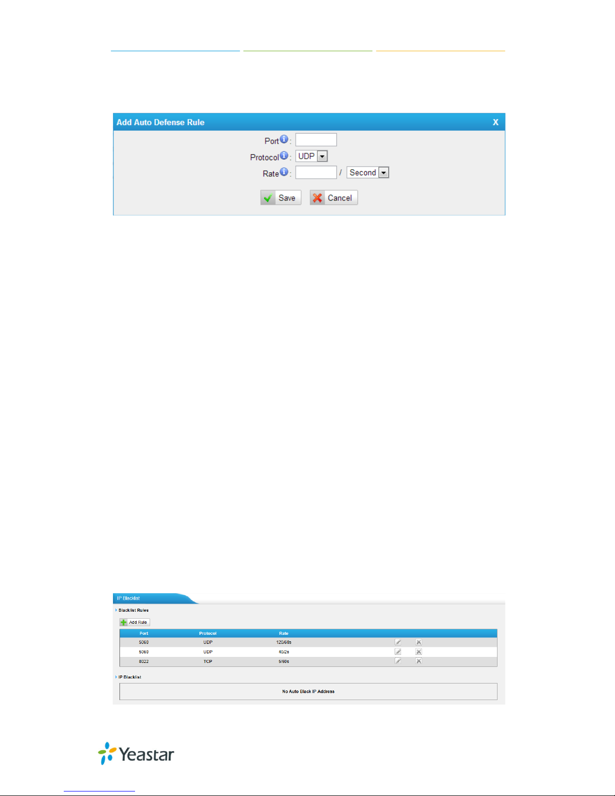
3) Auto Defense
By default,
there is no rule.
Figure 5-13
Port
The port you want to auto defense, for example, 8022.
Protocol:
Select the protocol. You can sel ect U DP or T C P.
Rate:
The maximum packets or connections can b e handled pe r uni t t ime .
For example, if you configure it as below:
Port: 8022
Protocol: TCP
Rate: 10/min
Then, it means ma ximum 10 TCP connec tion s can b e handle d in 1 minute. The
11
th
connection will be dropped.
5.2.3 IP Blacklist
You can set some packets accept speed rules here. Wh en a IP address which
hasn’t been accepted in co mmon rules sen ds packets faster than the allowed
speed, it will be set as black IP address and blocked automatically.
Figure 5-14
Page 29

MyPBX U100/U200 Administrator Guide
29/195
1) Blacklist rules
You can add the rules for IP blacklist rate as you wish.
Figure 5-15
·Port
Auto defense port
·Protocol
Auto def e n se protocol. TCP or UDP.
·IP Packets
Allowed IP packets number in the specific time interval.
·Time interval
The time interval to receive IP packets. For example, IP packets 90, time
interval 60 means 90 IP packets are allowed in 60 seconds.
2) IP blacklist
The blocked IP address will display here, you can delete it as you wish.
5.2.4 AMI Settings
The Asterisk Manager Interface (AMI) is a syst em monitoring and ma nagement
interface provided by Asterisk. It allows live monitoring of events that occur in
the system, as well enabling you to request that Asterisk perform some action.
The actions that are available are wide-ranging and include things such as
returning status information and originating new calls. Many interesting
applications have been developed on top of Asterisk that take advantage of the
AMI as their primary interface to Asterisk.
Page 30

MyPBX U100/U200 Administrator Guide
30/195
There are two main types of messages on the Asterisk Manager Interface:
manager events and manager actions.
The 3
rd
party software can work with MyPBX using AMI interface. It is disabled
by default. If necessary, you can enable it.
Figure 5-16
Username & password: after enabling AMI, you can use this username and
password to log in MyPBX AMI.
IP Restriction: you can set which IP can log in MyPBX AMI interface.
5.2.5 Database Grant
U100&U200 are using MySQL database from 14.18.0.22. The 3rd party software
can access MySQL via internet. Before that, you need to grant the authority to
the database user.
After entering “Database G rant” page, cli ckin g “Add”, you can add a dat abas e
user, set user passwo rd and gr a nt aut horit y.
Figure 5-17 Database Grant
Username/password: The 3rd party can use this username and password t o
access the MySQL.
Database: the re are 2 opt ions, CDR and R e cord. I f y ou choose CDR, t he n t hi s
user has authorit y t o check C DR da ta base ; if you cho ose Re cord , the n the use r
has authority t o che ck whi ch call has b e en record e d automatica lly.
Page 31
MyPBX U100/U200 Administrator Guide
31/195
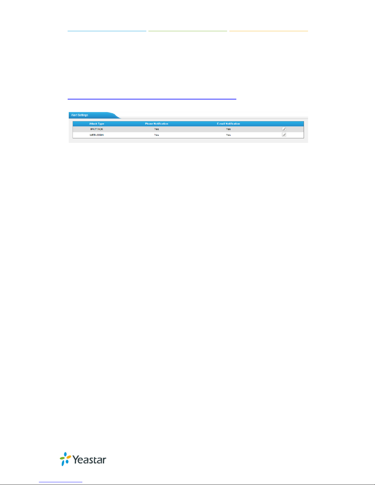
5.2.6 Alert Settings
If the device is attacked, the system will notify users the alert via call or E-mail.
The attack modes include IP attack and Web Login.
For more details on the system security configuration, please refer to
APPENDIX I MyPBX Security Configuration Guide.
Figure 5-18
1. IPATTACK
When the system is attacked by IP address, the firewall will add the IP to auto
IP Blacklist and notify the user if it match the protection rule.
1) Phone Notification Settings
·PHONE Notification
Whether enable p hone not ification.
·Number
The numbers could be set for alert notification; users can setup multiple
extension and out b ound p hone number s. Ple ase separate them by “;”.
Example: “500;9911”, if the extension has configured Follow Me Settings, the
call would go to the forwarded number directly.
·Attempts
The attemp t s t o dial a phone numb e r whe n t here is no answe r.
·Interval
The interval between each attempt to dial the phone number. Must be great e r
than 3 seconds, the de f a ult va l ue is 10 seconds.
·Prompt
Users will hear the prompt while receiving the phone notification.
2) E-mail Notification Settings
Note: Please ensure that all voicemail settings are properly configure d on t he
System Settings -> Voicemail Settings page before using this feature.
·E-mail Notification
Page 32

MyPBX U100/U200 Administrator Guide
32/195
Whether enable E-mail Notification or not
·Recipient’s Name
The recipients for the alert notification, and multiple email addresses are
allowed, please separate them by “;”.
Example: je rry @y e a star.com; jason@yeastar.com, 456@sina.com
.
·Subject
The subject of the alert email.
·Email Content
Text content supports predefined variables. Variable names and corresponding
instructions are as follows:
$(HOSTNAME) Host name
$(LOCAL IP) Loc al IP ad dress
$(SOURCEIP) Attack source IP add ress
$(DATETIME) Occurred
$(USERNAME) User name (WEBLOGIN effective)
$(DESTMAC) Attacks destination MAC (IPATTACK effective)
$(DESTPORT) Attacks destination Port num b er (IPATTACK eff ective)
$(PROTOCOL) Protocol type (IPATTACK effective)
$(INTERFACE) Network interface name (IPATTACK effective)
Page 33

MyPBX U100/U200 Administrator Guide
33/195
Figure 5-19
2. WEBLOGIN
Web Login Alert Notification: Enter the password incorrectly five times to login
MyPBX Web interface will be considered as an attack, the system will limit the IP
login within 10 minut e s a n d not if y t he use r.
Page 34

MyPBX U100/U200 Administrator Guide
34/195
Figure 5-20
5.3 LDAP
5.3.1 LDAP Serve r
LDAP is used as a phone book on MyPBX s o that you can search a key word from
your IP phone. The key word can be a name, a mobile number , an ema il or other
words in the phoneb ook.
Note:
It requires t hat the IP phone should sup port LDAP fea t ure .
1) LDAP Settings
Page 35

MyPBX U100/U200 Administrator Guide
35/195
Figure 5-21
·Enable LDAP
Enable LDAP to use LDA P on your IP phone.
·Root Node
A root node for this LDAP, e.g. dc=pbx, dc=com.
·PBX Node
A pbx node for this LDAP, e.g. ou=pbx, dc=pbx, dc=com.
·User Name
A user for this LDAP, e.g. cn=admin, dc=pbx, dc=com
·Password
A password used to a ccess LDAP.
2) Add Contact
In Add Contact you can create them as required.
Figure 5-22
If you wa nt to know how t o use LDAP, please refe r t o Appendix K
Page 36

MyPBX U100/U200 Administrator Guide
36/195
5.4 Storage Management
5.4.1 USB Device
MyPBX U100/U200 supports US B hard disk. If you enable recording add-on, you
can store the recording file in USB hard disk.
Y ou ca n c he ck t he inf orma t ion of the hard disk, manag e the disk a nd d o some
related configuration.
Figure 5-23
·USB Device Information
It’s the i nf orma t i on of the USB hard d is k.
·USB Devices Management
You can format, clean up or remove the USB device here.
Note: Please check if you need to back up these files before formatting or
clearing up the USB device. Don’t power off the device during the period.
5.4.2 External Storage
The External Storage feature is used to extend storage space. Once configured,
the files (voicemail, call recording files) created before the configured days will
be moved to the Net-Disk.
Note: The shared folder must be based on Windows Operation System. And if
it's windows Vist a /2 008 /7, pleas e add “Everyone ” int o t he shared account li st .
Page 37

MyPBX U100/U200 Administrator Guide
37/195
Figure 5-24 File Sharing
Before external storage can be properly configured, an SMB share folder
accessible from MyPBX must be set up on a Windows based machine. Once that
has been set up, please follow the steps below.
Figure 5-25 External Stora ge Settings
Page 38

MyPBX U100/U200 Administrator Guide
38/195
Step 1: Choose a window-based computer that is alwa ys in service
Step 2: Create a folder
Step 3: Create a text file named "status.txt" in the folder
Step 4: Share this folder
Then we need input the Net-Disk information in Step2 page.
Figure 5-26 Enter th e Net-disk information
Net-Disk Host/IP: Change this to the IP address of the computer where
backup files will be stored.
Net-Disk Share Name: Change this to the name of the shared folder w here
backups will be stored.
Net-Disk Share Username: The user name use d to log into the network share.
Leave this blank if it is not required
Net-Disk Share Password: T he password used t o log into the network share .
Leave this blank if it is not required
Open your Wind ows share folder to see if the MyPBX backup files and folders has
been created. If
the contents of the backup folder look similar to Step3 page,
then you hav e s ucce ssfully confi g ure d external storage on the MyPBX unit .
Figure 5-27 Configuring External Storage Successfully
Page 39

MyPBX U100/U200 Administrator Guide
39/195
5.5 System Preference
In this page, we can set other system preference, like the password for admin
account, system date and time, firmware update, hot standby, backup and
restore, reset and reboot.
5.5.1 Password Settings
MyPBX has 3 accounts: a d min, user, and cdr. Use r a nd cd r account is d isa b l ed
by default.
Admin account:
The default password for account “admin” is “password”. To change the
password, select “admin” in “User”, enter the old password and new password,
and click “Save”. The system will then prompt you to re-login using your new
password.
After you enter the new password, MyPBX will prompt the password strength. It
is recommended that you use numbers, upper-case letters, and lower-case
letters to increase the security.
When you log in MyPBX using “admin” a ccount, you can e nable “user” and “cdr”
account; also, you can cha ng e t he ir p a sswords.
Figure 5-28 Modify admin’s Passwo rd
User account:
User account is disabled by default and its default password is “password”.
When enabling “user” account for the first time, MyPBX will ask you to
change “user” password. If you don’t change it, you can’t enable “user”
account.
To change th e passw ord, select “us er” in “User”, enter the old passwor d and
new password, and click “Save”. The system will then prompt you to re-login
using your new p a s sword .
After you enter the new password, MyPBX will prompt the password strength. It
is recommended that you use numbers, upper-case letters, and lower-case
letters to increase the security.
Page 40

MyPBX U100/U200 Administrator Guide
40/195
Figure 5-29
After enabling “user” account, you can log in MyPBX using “user”. “user”
account can change its own password.
CDR account:
“cdr” account is disabled by default and its default password is “password”. Y ou
can enable it after you log in MyPBX using “admin” account.
To change the password, select “cdr” in “User”, enter the old password and new
password, and click “Save”. The system will then prompt you to re-login using
your new password.
After you enter the new password, MyPBX will prompt the password strength. It
is recommended that you use numbers, upper-case letters, and lower-case
letters to increase the security.
Figure 5-30
After enabling “cdr” account, you can log in MyPBX using “cdr”. “cdr ” account
can change its own pa ssword.
5.5.2 Date and Time
Set the date and time for MyPBX.
Page 41

MyPBX U100/U200 Administrator Guide
41/195
Figure 5-31
·Time Zone
Y ou ca n c hoose your time zone here.
·Daylight Saving Time
Set the mode to Automatic or disabled
·Automatically Synchronize With an Internet Time Server
Input the NTP server so that MyPBX will update the time automatically
·Set Date & Time Manually
You can set the time to your local right time manually here
5.5.3 Firmware Update
Upgrading of the firmware is possible through the Administrator web interface
using a TF TP Se rv e r or an HTTP URL.
Enter your TFTP Server IP address and firmware file name, then clic k start to
update the firmware
Notes:
1. If “Reset configuration to Factory Defaults” is enabled, the system will restore
to factory default settings.
2. When update the firmware, please don’t turn off the power . Or the system will
get damaged.
3. For more information on the steps of updating the firmware, please refer to
this link:
http://www.yeastar.com/download/MyPBX-U100_U200/MyPBX_U100&U200_F
irmwareUpgrade_cn.pdf
Page 42

MyPBX U100/U200 Administrator Guide
42/195
Figure 5-32
5.5.4 Backup and Restore
We can back up the configurations before resetting MyPBX U300 to factory
defaults, and then rest ore it usi ng thi s package. The ba ckup creat ed on MyPBX
is encrypted with file format ".bak".
Notes:
1. Only configurations, custom prompts will be backed up, the voicemail and
recording files are not included.
2. When you have updated the firmware version, it’s not recommended to
restore using old package.
Figure 5-33
·Create a New Backup
Users are able to create a new backup for “All” or for separated extensions.
Figure 5-34
·Upload a Backup
Users are able to upload backup for “Al” or for separate extensions.
Page 43

MyPBX U100/U200 Administrator Guide
43/195
Figure 5-35
5.5.5 Reset and Reboot
We can reset or reboot MyPBX U100&U200 via web directly in this page.
Figure 5-36
·Reboot System
Warning: Rebooting the system will termina t e a ll active calls!
·Reset to Factory Defaults
Warning: A factory reset will erase all configuration data on the system.
Please do not tu rn of f the syst em until the RUN light be gins blinki ng. Any po wer
interruption d uring this time coul d ca us e d a ma g e t o t he sy st e m.
5.5.6 Hot Standby
Redundancy is a chieve d by using duplicate ha rdware a nd software installations
and synchronizing data and operating state. Redundancy assures smooth
operation even if a system goes down. Essentially a duplicate backu p system
takes over with virtually no loss of service. This technique assures absolute
reliability no matter what failure occurs. In mission critical installations,
redundancy is a way to address possibility of any failure.
Note 1: Before enabling the Hot Standby feature, please m ake sure that the
Page 44
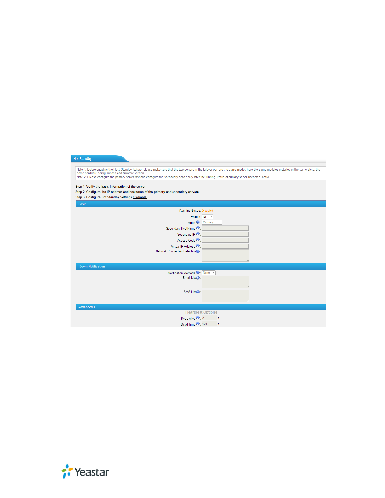
MyPBX U100/U200 Administrator Guide
44/195
two servers in the failover pair ar e the same model, own the same modules
installed in the same slots, the same hardware configurations and firmware
version.
Note 2: Please confi g ure t he prima ry se rv e r f i rst and configu re the secondary
server only a f t e r t he running status of p ri ma ry se rve r becomes “ a ctive”.
Note 3: The virtual IP address inputted in this page will be the one used for
registering in e a ch I P p hone.
Note 4: Before configuring the Email list in this page, please configure
the “voicemail settings” in “PBXBasic settings”, and make sure the SMTP test
successfully.
Note 5: Before configuring the SMS list; please make sure the SIM and
GSM/UMTS modules are installed well
Figure 5-37
Mode: Primary means the ma in unit; Secondary means t he st a nd by unit;
Secondary/Primary Hostname: If this unit mod e i s p ri ma ry, t he n you need
to input the hostname of standby unit; vice versa, if this unit is selected as
secondary, the n the hostname of primary u nit is required. In brie f, you need to
input each oth er’s h ost na me on this field.
IP: You need to inp ut e a ch othe r’s IP address on t his field.
Access code: To make an identification number to verify each other. The
number must b e t he sa me t o b ot h uni t s.
Virtual IP address: To fill in a virtual IP address includes mask, which is
always point s t o the currently a ct i vated unit. Customer can register I P phones
through this virtua l IP address. Plea se make sure the v irtual IP address netmask
Page 45

MyPBX U100/U200 Administrator Guide
45/195
is the same on b ot h units but diff e re nt from their former IP address .
Network Connection Detection: Generally it requires the IP address of the
router or gateway that connects both units. MyPBX will connect another unit
through this IP address.
Down Notification: The way of informing cust ome r t ha t t he sy st e m d own.
Keep Alive: Every 2 seconds, a packag e will be sent f rom one unit to anot her,
which can test w hether they are workin g p roperly.
Dead Time: The default setting is 12 0 seconds. If there’s no res ponse wi thin
120s after one receiving a package from the other, then the normal working unit
will figure the other unit is dead and send an email or SMS to report the failure.
Page 46

MyPBX U100/U200 Administrator Guide
46/195
6 PBX
Click to access “PBX” tab.
In this page, we can configure the settings of extension, trunk, inbound call
control, outbound call control, audio settings and the others. After configuring
the MyPBX, we can make or receive calls as sched ule d .
6.1 Extensions
In this page, we can configure the extensions’ details and provision the
supported models automatically.
6.1.1 FXS/VoIP Extensions
There are three types of extensions supported in MyPBX U100&U200: SIP, IAX
and analog e xt e nsi on.
Note:
1. The max number of SIP/IAX extension is 100 for U100, 200 for U200.
Figure 6-1
FXS Extensions
Page 47

MyPBX U100/U200 Administrator Guide
47/195
Figure 6-2
There are two analog extensions in MyPBX U100&U200 if S2 module is installed.
To modify the extension number, please delete it first, then recreate it again.
1) General
Figure 6-3
·Extension
The numbered extension, e.g. 1234, that will be associated with this particular
User / Phone.
·Port
The extension correspond port.
·Name
A character-based name for this user, e.g. “Bob Jones”.
·Caller ID
The Caller ID (CID) string will be used w hen this user calls anothe r internal user.
Page 48

MyPBX U100/U200 Administrator Guide
48/195
2) Voicemail
·Enable Voicemail
Check this box if t he use r should have a voice ma i l a c count .
·Voicemail Access PIN #
Voicemail Password for this extension, e.g. “1234”.
3) Mail Setting
·Enable Send Voicemail
Once enabled, the voicemail will be sent to the below email address as an
attachment.
·Send Voicemail to Email Address
This option defines whether or not voicemails/Fax is sent to the Email address
as an attachment.
Note: Please ensure that all voicemail settings are properly configured on the
System Settings -> Voicemail Settings page before using this feature.
4) Flash
·Hook Flash Detection
Sets the amount of time, in milliseconds, that must pass since the last
hook-flash event received by MyPBX before it will recognize a second event. If a
second event occurs in less time than defined by Hook Flash Detection, then
MyPBX will ignore the event. The default value of Flash is 1000 ms, and it can be
configured in 1ms i ncrements.
5) Group
·Pickup Group
If this extensi on belongs to a pickup group, any calls that ring t his extension can
be picked up by other extensions in the same pickup group by dialing the Call
Pickup feature code (the default is *4).
Note: *4 is the default setting, it can be changed under Feature Codes ->
General -> Call Pickup.
6) Call Duration Setting
Set the max call duration for this extension. This setting is effective when this
extension makes calls. For example, if m ax call du ration of extension 601 is
300s, when 601 makes calls, the call will be disconnected b y MyPBX after 300s.
If max call duration is set to 0 or empty, it will follow global max call duration
setting in “SIP Settings” .
Note: This setting will not be valid for internal calls.
Page 49

MyPBX U100/U200 Administrator Guide
49/195
Other Settings
Figure 6-4 FXS Extensio n Other Settin gs
7) Other options
·Call Waiting
Check this option if the extension should have Call Waiting capability. If this
option is checked, the “When busy ” follow me options will not be available.
·DND
Don’t Disturb.
·User Web Interface
Check this option to allow the user to login to the MyPBX User Web interface,
which can be used to acce ss voice ma il a nd e xt e nsion recordings. Users may
login to the MyPBX User Web interface by using their extension number and
voicemail PIN as the login and password respectively.
·Ring Out
Check this option if you want to custom the ring time. Tone will stop over the
time defined.
8) Follow me (Call Forwarding)
Page 50

MyPBX U100/U200 Administrator Guide
50/195
This function set s inbound call f orwarding on an extension. An administrator can
configure Follow Me for this extension.
9) Volume Settings
Rxgain: The Volume sent to FXS e xt e nsi on.
Txgain: The V olume se nt out b y t he F XS e xt ension
10) Mobility Extension
MyPBX allows you to use your mobile phone as an ex tension. If you set your
mobile phone as a mobility extension and t hen you call MyPBX with this mobility
phone, you will hear a dial tone. MyPBX will recognize your call as a call from an
extension. You can dial the number of other extensions (your caller ID will be
the number of your extension) or dial out via outbound routes just like dialing
from your ext e nsi on.
Note: If callback is enabled in the inbound route, the mobility extension
function of this inbound route will be disabled.
·Enable Mobility Extension
Enable to feature.
·Mobility Extension Number
When you dial the server with this number, the mobile gets the permission of
the extension. For example: dialing the other extensions, playing the voicemail.
·Ring Simultaneously
When the extension has an incoming call, it rings its mo bility extension
simultaneously.
·Outbound Prefix
Fill in a proper pref ix of mobile number so t hat it ca n mat ch an outbound route
to dial the mobility extension. For example, if you set the prefix to “9”, it will
send “9 + mobility extension number” to the outbound route.
11) Spy Settings
MyPBX allows extension to monitor/barge in other conversation. Once this
feature is enab led, the ext ension ha s the a bil ity to monitor/barg e in ot her cal ls
using the feature codes for each spy mode. Refer to “Feature Codes” section for
more informa t ion.
·spy modes
There are 4 spy modes available:
Normal spy: y ou ca n only he a r t he ca l l, b ut can't t a lk
Whisper spy: yo u can hear the ca ll , a n d ca n talk wit h t he moni t ored e x t e nsion
Page 51

MyPBX U100/U200 Administrator Guide
51/195
Barge spy: you can hear the call and talk with them both
General spy: you can choose to use one of the above 3 spy modes
Note: for example, if 500 want to monitor extension 501, we need to enable the
“allow being spied” for 501, and choose the spy mode for extension 500.
Then pick up 500 and d i a l “feature cod es + 501” to sta rt monitoring when 501
is in a call
If 500 choose “normal spy”, it should dial “*90501” to start monitoring.
If 500 choose “whisper spy”, it should dial “*91501” to start monitoring.
If 500 choose “barge spy”, it should dial “*92501” to start monitoring.
If 500 choose “general spy”, it can dial “*90501”, “*91501” or “*92501” to start
monitoring.
VoIP Extensions
A VOIP extension is a SIP/IAX Account that allows an IP Phone or an IP SoftPhone client to register on MyPBX
Figure 6-5
We can click “Add extension” to start.
Page 52

MyPBX U100/U200 Administrator Guide
52/195
Figure 6-6
1) General
·Type
Extension type : S I P, IAX or SIP/IAX.
SIP – The extension sends and receives calls using the VoIP protocol SIP.
IAX -The extension sends and receives calls using the VoIP protocol IAX.
·Extension
The numbered extension, e.g. 1234, that will be associated with this particular
User / Phone.
·Password
The password for this extension, but it is not a fixed one. When you add new
extension, a random and robust password will be generated like “Gtwfup642”.
·Name
A character-based name for this user, EX: “Bob Jones”
·Caller ID
Page 53

MyPBX U100/U200 Administrator Guide
53/195
The Caller ID w il l b e use d whe n t his us e r ca ll s a not he r i nt e rna l e x t ens ion.
·Register Name
It is for extension registration validation. Users will not be able register the
extension if t he authorizati on name is incorrect even though t he username and
password are correct.
2) Voicemail
·Enable Voicemail
Check this box if t he use r should have a voice ma i l a c count .
·Voicemail Access PIN
The voicemail Password for this extension, e.g. “1234”.
3) Mail Setting
This option def i ne s whe t he r or not voicemails or faxes are sent to an Email
Address as an attachment.
·Enable Send Voicemail
Once enabled, the voicemail will be sent to email as an attachment.
·Email Address
Email address used to receive the voicemail or Fax.
Note: Please ensure that the section “SMTP Settings For Voicemail” (in the
“Voicemail Settings”) have been properly configured before using this feature.
4) Group
·Pickup Group
If this extensi on belongs to a pickup group, any calls that ring t his extension can
be picked up by other extensions in the same pickup group by dialing the Call
Pickup feature code (the default is*4).
Note: *4 is the default setting, it can be changed under Feature Codes ->
General -> Call Pickup.
5) Call Duration Settings
Set the max call duration for this extension. This setting is effective when this
extension makes calls. For example, if m ax call duration of extension 306 is
300s, when 306 makes calls, the call will be disconnected by MyPBX after 300s.
If max call duration is set to 0 or empty, it will follow global max call duration
setting in “SIP Settings”.
6) VoIP Settings
·NAT
This setting should be used w hen t he sy st em is using a public IP address to
Page 54

MyPBX U100/U200 Administrator Guide
54/195
communicate w it h devices hidd e n b e hi nd a NAT d e vic e (such as a broadb and
router). If you ha v e one -way audio problems, you usually have problems with
your NAT config ura t i on or your firewall 's sup port of S I P a nd /or RTP p orts.
·Qualify
Send check alive packets to IP phones
·Enable SRTP
Enable ext ens ion f or S RTP (RTP Encryption).
·Transport
This will be the transport method used by the extension. The options are UDP
(default) or TCP or TLS.
·DTMF Mode – RFC2833, Info, Inb a nd, A uto.
·Register Remotely
If you want t o re g is t e r remot e e xt e nsi on, you s hould e na b l e t his op t ion.
Other Options
Figure 6-7 VOIP Extension Other Setting s
Page 55

MyPBX U100/U200 Administrator Guide
55/195
7) Other Options
.Call Waiting
Check this option if the extension should have Call Waiting capability. If this
option is checked, the “When busy” follow me options will not be available. The
call waitin g f unction of IP phone ha s hig her priority than MyPBX’s call waiting
function.
.DND
Don’t Disturb. W hen DN D is e nab led f or an e xtensi on, the e xtensi on wi ll n ot be
available.
.User Web Interface
Check this option to allow the user to login to the MyPBX User Web interface,
which can be used to check voicemail and extension recordings. Users may login
to MyPBX User Web interface by using their extension number and voicemail
PIN # as the login and password re sp ect iv el y.
.Ring Out
Check this option if you want to customize th e ring time. Ring tone will stop over
the time defined.
8) Follow me (Call Forwarding)
Call forwardi ng f or an ext ension ca n be conf igured he re. The administrator can
configure Foll ow Me option for this extension. If you want to tra nsfe r the ca ll t o
an outbound number, please follow the dial pattern of outbound route filled in
the outbound numb e r.
For example: transferring t o your m obile p ho ne number 123456789, the dial
pattern of out b ound rout e is “9.”, you sho uld f ill i n 9123456789 here.
9) IP Restriction
·Enable IP Restriction
Check this option to enhance the VoIP security for MyPBX. If this option is
enabled, only the permitted IP/Subnet mask will be able to register this
extension number. In this way, the VoIP security will be enhanced.
·Permitted “IP address/Subnet mask”
The input forma t shoul d b e “IP address”+ “/”+ “Subnet mask ”.
e.g."192.168.5.100/255.255.255.25 5" mea ns only the device whose IP
address is 192.168.5.100 is a llowed t o reg ist er this e xt e nsi on number.
e.g."192.168.5.0/255.255.255.0" means onl y the device whose I P ad d ress is
192.168.5.XXX is allowed t o regi ste r this e xt ension number.
10) Mobility Extension
MyPBX allows you to use your mobile phone as an extension. If you set your
Page 56

MyPBX U100/U200 Administrator Guide
56/195
mobile phone as a mobility extension and then you call MyPBX with this mobility
phone, you will hear a dial tone. MyPBX will recognize your call as a call from an
extension. You can dial the number of other extensions (your caller ID will be
the number of your extension) or dial out via outbound routes just like dialing
from your ext e nsi on.
Note: If callback is enabled in the inbound route, the mobility extension
function of this inbound route will be disabled
·Enable Mobility Extension
Enable this f e ature.
·Mobility Extension Number
When you dial the se rv er w it h t hi s numb e r, t he mob i le phone gets the
permission of the extension. For example: dialing the other extensions, playing
the voicemail.
·Ring Simultaneously
When the extension has an incoming call, it rings its mobility extension
simultaneously.
·Outbound Prefix
Fill in a proper pref ix of mobile number so t hat it ca n mat ch an outbound route
to dial the mobility extension. For example, if you set the prefix to “9”, it will
send “9 + mobility extension number” to the out b ound route.
11) Spy Settings
MyPBX allows extension to monitor/barge in other conversation. Once this
feature is enab led, the ext ension ha s the a bil ity to monitor/barg e in ot her cal ls
using the feature codes for each spy mode. Refer to “Feature Codes” section for
more informa t ion.
·spy modes
There are 4 spy modes available:
General spy: you have the permission to use the following 3 modes.
Normal spy: you can only hear the call, but can't t a l k
Whisper spy: yo u ca n he a r t he call, and ca n talk with the monitored extension
Barge spy: y ou ca n he a r t he call and talk with t he m b ot h
Note: for exa mple, if 500 want to monitor extension 501, we need to enable the
“allow being spied” for 501, and choose the spy mode f or ext e nsion 500.
Then pick up 500 and dial “fea t ure code s + 501” to start monitoring w he n 501
is in a call.
If 500 choose “normal spy”, it should dial “*90501” to start monitoring.
If 500 choose “whisper spy”, it should dial “*91501” to start monitoring.
Page 57

MyPBX U100/U200 Administrator Guide
57/195
If 500 choose “barge spy”, it should dial “*92501” to start monitoring.
If 500 choose “general spy”, it can dial “*90501”, “*91501” or “*92501” to start
monitoring.
6.1.2 Phone Provisioning
The Auto Provision sub menu provides users a method to Auto Provision IP
Phone after the Express Setup process.
Note: Auto Provision functions fully test with these models:
Yealink (T12, T18, T19, T20, T21, T22, T26, T28, T32, T38, T41, T42, T46,
W52P, VP5 30, VP-2009)
Snom (300, 320, 360, 370)
Polycom (IP 6000, IP 7000, IP 32X, IP33X, IP430, IP450, IP550, IP560,
VVX1500)
Cisco (IP7940, IP7960)
Aastra (9480i, 9480i-CT, 6730i, 6731i, 6737i, 6753i, 6755i, 6757i , 6757i CT)
GrandStream (GXP1450, GXP2 100, G XP 2110, GXP2120)
Escene (ES220, ES320, ES330, ES410, ES620)
Fanvil (C56, C58, C60, C62)
Panasonic (UT113, UT123, UT13 3, U T136, U T248, UT670, TGP5 00, TGP550)
News:
When provisioning Yealink and Snom IP phone, MyPBX is not needed to
be set as the only DHCP server any more.
Figure 6-8
Page 58
MyPBX U100/U200 Administrator Guide
58/195
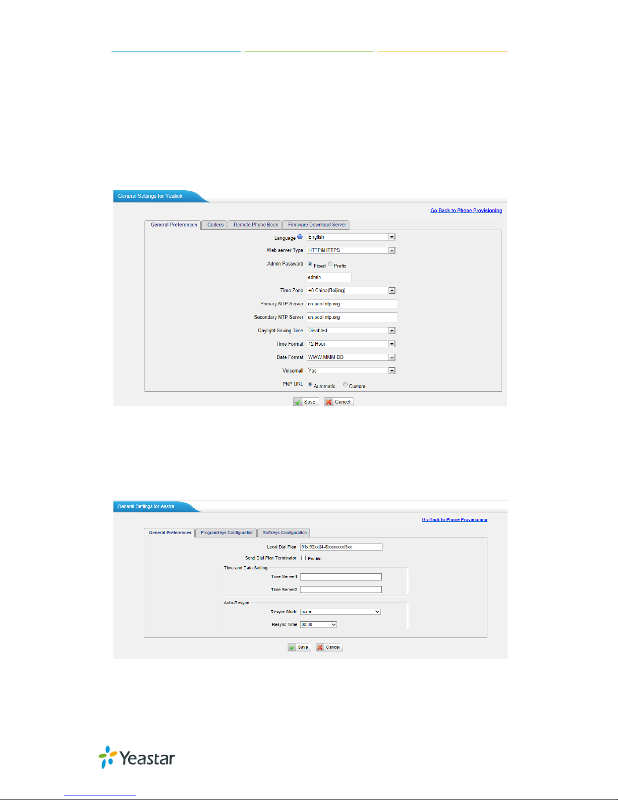
6.1.2.1 General Settings for Yealink
In this page, you can config ure the general settings before provisioning Yealink
IP phones, including the items like general preferences, codecs, remote phone
book and firmware upgrade.
Note: if firmware download server is enabled, IP phone will update the
firmware a utomatically according to the version and server you have configured
during the provision process.
Figure 6-9
6.1.2.2 Aastra General Settings
In this pag e , you ca n c onf igure the general settings before provisioning Aastra
IP phones, including the items like general preferences, program keys
configuration, soft keys conf i g ura t i on.
Figure 6-10
Page 59

MyPBX U100/U200 Administrator Guide
59/195
6.1.2.3 Phone book
You can add your contacts here and when you use phone provisioning; the IP
will download the phone book.
Figure 6-11
1) Add Contact
·Type
There are three types: None, VIP and Deny list (Blacklist).
·Group
There are 5 groups: None, Friends, Family, Work, Colleagues list.
·Nick Name
You can set a nick na me f or t hi s numb e r.
·Favorite
Only works with snom phone.
·Organization
Input the org a ni zation of this cont a ct . Only w orks wi t h snom phone.
·Title
Input the t i t le of t hi s cont a c t . Only works w it h snom phone.
·Email
Input the e ma i l of thi s cont a c t . Only works w ith snom phone .
·Birthday
Input the b i rt hd a y of t hi s cont a ct . Only w orks with snom pho ne.
·First Name
Input the first name of this cont a c t . Only works with snom pho ne .
Page 60

MyPBX U100/U200 Administrator Guide
60/195
·Family Name
Input the fa mil y of t hi s cont a c t . Only works w ith snom phone .
·Office Number
Input the of fice number here
·Mobile Number
Input the mob i le numb e r he re
·Home Number
Input the home numb e r he re
·Sub Number
Add sub numbe r of t hi s cont a ct. Only works wit h snom p hone.
·Note
Take some note of t hi s cont a c t . Only works with snom p hone.
Figure 6-12
Page 61

MyPBX U100/U200 Administrator Guide
61/195
2) Upload Phonebook
You can upl oad a p honebo ok bef ore aut o prov ision, which will be provisioned to
the IP phone whe n using auto pr ovision feature t o configure your IP ph ones. The
format of p h one book should be *.xml .
Note: All the existing phonebooks of the IP phone will be replaced automatically
if the phoneb ooks a re conf igured in this wa y .
6.1.2.4 Configure phone
Let's take p rovis ioning Yealink as an example.
There are t wo modes to create new phones: create new phones in webpage and
upload the IP Phone’s conf ig u ration file.
Add new phone via webpage
Click “Add Phone” and fill in the corresponding information in the pop-up
window.
Figure 6-13
1) General
·Enabled
Choose yes or no to enable or disable this extension
Page 62

MyPBX U100/U200 Administrator Guide
62/195
·New Config
If your IP phone’s firmware version is above x.70.x.x, you should select “Yes”.
Or else, it should be “No”.
· MAC address
Input the MAC address of the IP phone
·Name
Put the name of t hi s Phone here.
·Manufacturer
You can choose the M a nuf acturer of the IP phone
·Phone Type
Choose the mode l of y our p ho n e. Only for snom p hone
·Call Waiting
This call feature allows your phone to accept other incoming calls to an
extension already in an active call.
·Key as Send
Configure a key as the send key, you choose #, * or disable this feature
·Auto redial
Enable or disable the auto redial for the IP Phone
·Auto answer
Enable or disable auto answer for the IP phone
·Phone book
Enable or disable the featu re of phon e b ook of for the IP phone
·Line
You can set eac h li ne of I P p hone for the account you want, active or not .
Extension: Selected the extension number for IP Phone.
Label: It is shown on the LCD for users t o i d e nt ify the account.
Line Active: You can choose on/off to enable/disable the account respectively.
2) Codecs
In this page, we can se t the cod ecs for the IP phone.
Page 63

MyPBX U100/U200 Administrator Guide
63/195
Figure 6-14
3) Memory key settings
In this pag e , we ca n c onf ig ure t he DS S k e ys of the IP phone one by one .
Figure 6-15
Page 64

MyPBX U100/U200 Administrator Guide
64/195
4) Line keys settings
We can configure the li ne ke y s ettings for thi s IP phone.
Figure 6-16
6.1.2.4 Not configured phone
In this section, MyPBX will scan all the supported IP phones and display them.
We can click the “MAC address” of an IP phone and input the corresponding
information in the p op -up window, like figure 6-13.
Figure 6-17
6.1.2.5 Upload a file
Click “Upload a file” and choose the configure file of IP phon e in the popup
window.
Note: the file format must be .cfg
Please edit the configuration files in advance before uploading.
Figure 6-18
Page 65

MyPBX U100/U200 Administrator Guide
65/195
6.2 Trunk s
6.2.1 Physical Trunk
Multiply physical trunks are supported in MyPBX U100&U200, like BRI, P STN ,
and GSM/UMTS, pl eas e make sure you have installed the modules inside, BRI
trunk requires B2 module, PSTN trunk requires the O2, while for GSM/UMTS
trunk, and please install the GSM/UMTS modules inside.
Figure 6-19
BRI Trunk
Basic Rate Interface (BRI, 2B+D, 2B1D) is an Integrated Services Digital
Network (ISDN) configuration intended primarily for use in subscriber lines
similar to those that have long been used for plain old telephone service. Th e
BRI configur ation provide s 2 bearer channel s (B channels) at 64 k bit/s each and
1 data channe l ( D channel) at 16 k bit/s. The B channels are used for voice or
user data, and the D channel is used for any combination of data,
control/signalling, and X.25 packet networking
Figure 6-20
Click edit to configure the d e t a il s of BRI t runk s
Page 66

MyPBX U100/U200 Administrator Guide
66/195
Figure 6-21
·Trunk Name
A unique label used to identify this trunk when listed in outbound rules,
incoming rules, etc. E.g. “BriTrunk1”.
·Signaling
Signaling method
BRI-CPE: ISDN BRI in T E mod e and Point to Point .
BRI-CPE-PTMP: ISDN BRI in TE mode and Point to multi Point.
BRI-NET: ISDN BRI in NET mode and Point t o Point .
BRI-NET-PTMP: ISD N BRI i n NET mod e a nd Point t o mult i Poi nt.
·Switch Type
National: National ISDN type2 (common in the US)
ni1: National ISDN type 1
dms100: Nortel DMS100
Page 67

MyPBX U100/U200 Administrator Guide
67/195
4ess: A T &T 4ESS
5ess: Lucent 5ESS
euroisdn: Eur oISDN
qsig: D-channel signaling protocol at Q reference point for PBX networking.
·Over Lap Dial
Define whether MyPBX can dial this switch u sing overlap digits or not. If yo u
need Direct Dial-in (DDI; in German "Durch wahl") you should change this to yes,
then MyPBX will wait after the last digit it receives.
·Reset interval
Set the time in s ec ond s b e t we e n re st a rt of unused channels. So me PBX s d on't
like channel restarts. So set the interval to a very long interval e.g. 100000000
or “never” to disable entirely. If you are in Israel, the following is important: As
Bezeq in Israel doesn't like the B-Channel resets happ e ni ng on t he li nes , i t is
best to set the reset interval to “never” when insta lling a box in Isra el. Our past
experience also show s t ha t thi s p a ra met e r may also ca use issue s on local
switches in the U K and China.
·PRI Indication
Tells how Device should indicate Busy() and Congestion() to the switch/user.
Accepted values are:
inband: Device plays indication tones without answering; not available on all
PRI/BRI subscription lines .
outofband: Device disconnects with busy/congestion information code so the
switch will play the indication tones to the caller. Busy() will now do same as
setting PRI_CAU SE=17 and Hangup().
·Enable Facility
To enable transmission of facility-based IS DN sup p le ment a ry se rvices (such as
caller name from CPE over facility) .
·NSF
Used with AT&T PRIs. If outbound calls are being rejected due to "Mandatory
information element missing" and the missing IE is 0x20, then you need this
setting.
·Echo Cancellation
Disable or enable echo cancellation; it is recommended not to turn this off.
·Hide Caller ID
If you want others to see your CID, please disable this option.
·Codec
Page 68

MyPBX U100/U200 Administrator Guide
68/195
You can choose alaw or ulaw.
1) Caller ID Prefix
·ISDN Dialplan
These settings are set to make the caller ID prefix work according to information
sent from the E1 provider. ISDN telephony numbering plan Recommendation
E.164.
·International Prefix
When there are int ernational calls co ming in via this BRI t runk, the Internat ional
Prefix you have set here will be added before the CID. So you can know this is
an international call before you answer it.
·National Prefix
When there are national calls comin g in via t h is BR I trunk, the Nation al Pr efix
you have set here will be adde d before the CID. So you can know this is a
national call before you answer it.
·Local Prefix
When there are Local calls coming in via this BRI trunk, the Local Prefix you
have set here will be added before the CID. So you can know this is a local call
before you answer it.
·Private Prefix
When there are Private calls coming in via this BRI trunk, the Private Prefix you
have set here will be added before the CID. So you can know this is a Private call
before you answer it.
·Unknown Prefix
When there are calls with unknown number coming via this BRI trunk, the
Unknown Prefix you set here will be shown as the caller ID.
2) Dialplan
·Remote Dialplan
Calling number type
·Remote Number Type
Calling number identification
·Location Dialplan
Called number type
Page 69

MyPBX U100/U200 Administrator Guide
69/195
·Location Number Type
Called number identification
3) DOD Setting
DOD (Direct Outward Dialing) means the caller ID displayed when dialing out.
Before configuring this, please make sure the provider supports this feature.
·Global DOD
Global Direct Outward Dialing Number
·DOD
Direct Outward Dialing Number.
·Associated Extension
The extension making call out via BRI Trunk will display the associated DOD.
·Add DOD
Add DOD for one associated e xt e nsion.
·Add Bulk DOD
Figure 6-22 Add Bulk DOD
Add bulk DOD for bulk extensions in asce ndin g seq uence with the “Begin DOD”
you fill in. For example, if the Associated Extensions a re 100 , 101, 102, 103,
104, 105 with “Begin DOD” as 5500100, the correspo nd ing DOD will b e
5500100, 5500101, 5500102, 5500103, 5500 104, and 5500105.
Page 70

MyPBX U100/U200 Administrator Guide
70/195
PSTN trunk
The public switched telephone network (PSTN) is the network of the world's
public circuit-switched telephone networks
Figure 6-23
Click edit to configure more details.
Figure 6-24
·Trunk Name
A unique label used to identify this trunk when listed in outbound rules,
incoming rules, etc. E.g. “pstn5”.
·Volume Setting
Used to modify the volume level of this trunk. Normally, this setting does not
need to be changed.
Page 71

MyPBX U100/U200 Administrator Guide
71/195
1) Hangup Detection
·Busy Detection
Busy Detection is used to detect far end hang-up or for detecting a busy signal.
Select “Yes” to turn this feat ure on.
·Busy Count
If Busy Detect ion is enab led, it is also p ossible to sp ecify how many bu sy tone s
to wait for before disconnecting the call. The default is 4, but better results can
be achieved if set to 6 or even 8. Remember, the higher the number, t he more
time will be required to release a channel. A higher setting lowers the probability
that you will encounter random hang-ups.
·Busy Interval
The busy detection interval
·Busy Pattern
If Busy Detection is enabled, it is also possible to specify the cadence of your
busy signal. In many Countries, it is 500 msec on, 500 msec off . Without Busy
Pattern specified, MyPBX will accept any regular sound-silence pattern that
repeats <Busy C ount> times a s a busy signa l. If you specify Busy Pattern, then
MyPBX will further check the length of the tone and silence, which will further
reduce the chance of a f alse p osit iv e d i sconnect ion.
·Frequency Detection
Used for Frequency Detection (Enable detecting the bu sy signal frequency or
not).
·Busy Frequency
If the Frequency Detection is enabled, you must specify the local frequency.
·Hangup Polarity Reversal Detection
The call will be considered as “hang up” on a polarity reversal.
2) Answer Detection
·Answer Detection
Answer Detection settings are configured for accurate billing. I f the PSTN trunk
sends polarity af ter answering the call, users ca n choose "Polarity Detecti on"; or
else choose "Ring Detection", and configure the detailed settings accordin g to
the PSTN line ring tone.
3) Caller ID setting
·Caller ID Start
This option allows you to define the start of a Caller ID signal:
Page 72

MyPBX U100/U200 Administrator Guide
72/195
Ring: Start when a ring is received (Caller ID Signaling: Bell_USA, DTMF).
Polarity: Start when a polarity reversal is started (Caller ID Signaling: V23_UK,
V23_JP, DTMF).
Before Ring: Start before a ring is received (Caller ID Signaling: DTMF).
·Caller ID Signaling
This option defines the type of Caller ID signaling to use. It can be set to one of
the following:
Bell: bell202 as used in the United States
v23_UK: suitable in the UK
v23_Japan: suitable in Japan
v23-Japan pure: suitable in Japan
DTMF: suitable in Denmark, Swe d e n, a nd H olland
.Caller ID Detection
For FXO trunks, this option forces MyPBX to clarify Caller ID incoming calls
GSM/UMTS Trunk
GSM/UMTS trunks are supported in MyPBX Standard V7 if you have got the
GSM/UMTS module and SIM cards installed. One GSM/UMTS trunk supports
only one SIM card f or one concurrent ca l l.
Figure 6-24
Click edit to configure more details.
Figure 6-25
Trunk Name
A unique label used to identify this trunk when listed in outbound rules,
incoming rules, etc. E.g. “GSM/UMTS9”.
Page 73

MyPBX U100/U200 Administrator Guide
73/195
·Volume Setting
Used to modify the volume level of this trunk. Normally, this setting does not
need to be changed.
·PIN Code
Please enter your SIM card PIN code here if your card has a PIN code.
6.2.2 VoIP Trunk
There are two t ype s of VOI P trunk i n MyPBX: SI P and IAX, in this p ag e, we can
also configure the “service prov ider” trunk, which doesn’t need the use name
and passwor d for autho rization, when you have bought a trunk from provide
with IP address only, please choose “service provider” trunk .
Figure 6-26
6.2.2.1 VoIP Trunk
In this pag e, we can config ure VoI P trunk (SIP/ IAX ) you have got from pr ovider
with the authorization name and password.
Figure 6-31
1) Add VoIP Trunk
Input the correct SIP information (provided by VoIP provider). Inaccurate
information will prevent the trunk from registering. You can delete multiple
trunks at once as required.
Page 74
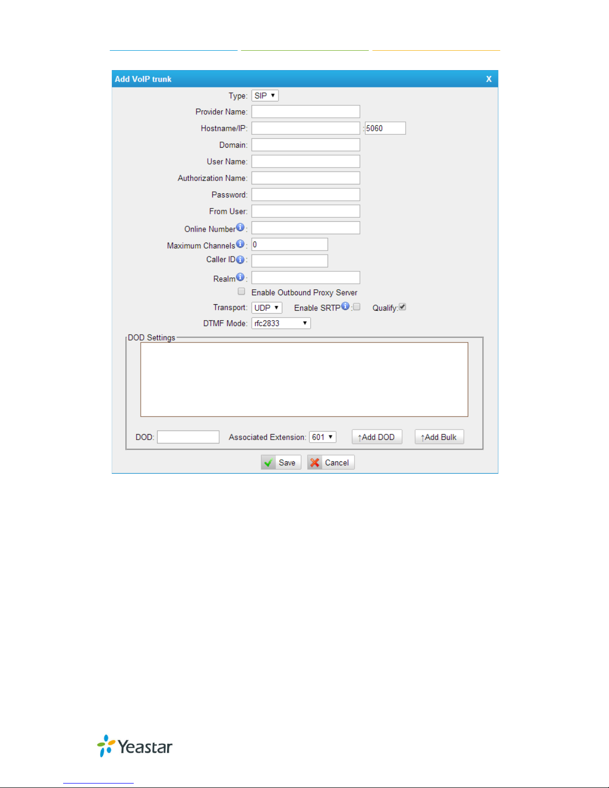
MyPBX U100/U200 Administrator Guide
74/195
Figure 6-27
·Type
SIP – Identifies whether the trunk sends and rec ei ve s c a ll s usi ng t he V oI P
protocol SI P
·Provider Name
A unique label to help you identify this trunk when listed in outbound rules,
incoming rules etc. E.g. “yeastar”.
·Hostname/IP
Service provider’s hostname or IP address.5060 is the standard port nu mber
used by SIP protocol. Don’t change this part if it is not required.
.Domain
VoIP provider’s server d oma i n na me .
Page 75

MyPBX U100/U200 Administrator Guide
75/195
·Username
Username of the SIP account. U sed for SIP trunk registration.
.Authorization name
Used for SIP authentication. Leave this blank if not re q ui red.
·Password
Password of the SIP account.
.From User
All outgoing calls from this SIP Trunk will use the From User (In this case the
account name f or SI P Reg i st ra t i on) in From Hea der of the SIP Inv it e package.
Keep this field blank if not needed
.Online number
Define the online number that expected by “Skype Connect” and some other SIP
service providers. Leave this field blank if not needed.
·Maximum Channels
Controls the ma ximu m number of outbo und cha nnels (si mult ane ous calls) that
can be used on this trunk. I nbound calls are not counted against the maximum.
Set as 0 to specify no maximum.
·Caller ID
Specify t he c a ll e r ID to use w hen making outbound ca l ls ove r t his t runk. The
caller ID set in the “extension” page will override t he caller ID set in the “VoIP
trunk” page. Please note that not all the service providers support this feature.
Contact your service provider for more information.
·Outbound Proxy Server
A proxy that receives requests from a client. Even though it may not b e t he
server resolved by the Request-URI.
·Codecs
Define the codec for this sip trunk and its priority
Note: T o change the codec type and priority of this trunk, please create it first,
it will appear when you edit it again.
·Transport
This will be t he transport meth od used by the SIP Trunk . This method i s given by
the SIP trunk provider. The options are UDP (default) or TCP or TLS.
·Enable SRTP
Page 76
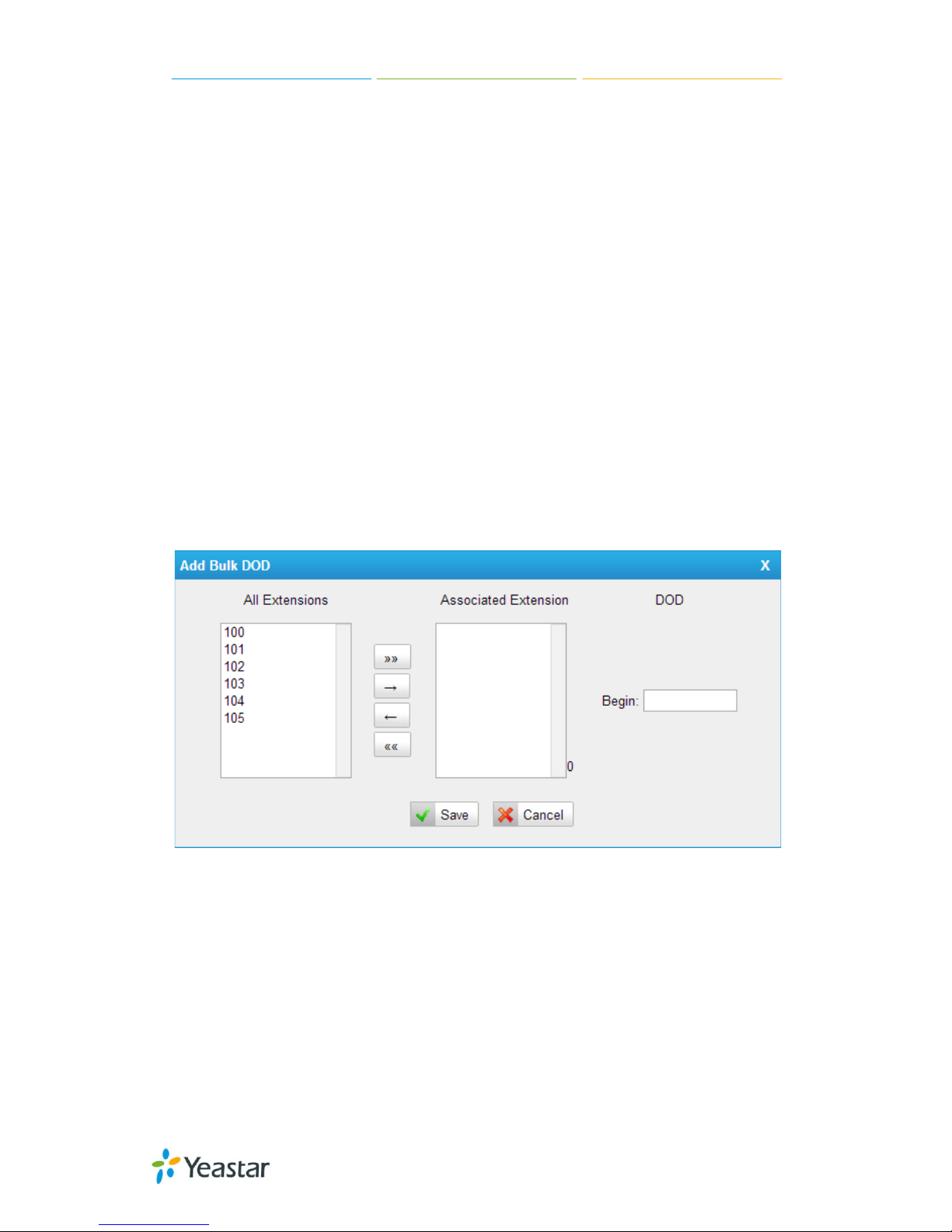
MyPBX U100/U200 Administrator Guide
76/195
Define if SRTP is enabled for this trunk
·Qualify
Send check alive packets to the sip provider.
·DTMF mode
Set default mode for sending DTMF of this trunk. Default setting: rfc2833
·DOD
DOD (Direct Outward Dialing) means the caller ID displayed when dialing out.
Before configuring this, please make sure the provider supports this feature.
·Associated Extension
The extension making call out via SIP Trunk will disp lay t he associated DOD.
·Add DOD
Add DOD for one associated e xt e nsion.
·Add Bulk DOD
Figure 6-28
Add bulk DOD for bulk extensions in asce ndin g seq uence with the “Begin DOD”
you fill in. For example, if the Associated Extensions are 100, 101, 102, 103,
104, 105 with “Begin DOD” as 5500100, the corresponding DOD will be
5500100, 5500101, 5500102, 5500103, 5500 104, and 5500105.
Page 77

MyPBX U100/U200 Administrator Guide
77/195
2) Add IAX trunk
Input the correct IAX information (provided by VoIP provider). Inaccurate
information wi ll p re v en t t he t runk f rom registe ri ng .
Figure 6-29
·Type
IAX – Identifies whether the trunk sends and receives calls by using the VoIP
protocol IA X .
·Provider Name
A unique label to help you identify this trunk when listed in outbound rules,
incoming rules etc. E.g. “yeastar2”.
·Hostname/IP
Service provider’s hostname o r IP address. 4569 is the standard port n umbe r
used by IAX protocol. Don’t change t hi s p a rt i f it is not re q ui red.
·Username
Username of IAX a ccount; Used for IAX trunk registration.
·Password
Password of IAX a ccount
Page 78

MyPBX U100/U200 Administrator Guide
78/195
.Online number
Define the online number that expected by “Skype Connect” and some other SIP
service providers. Leave this field blank if it's no required.
·Maximum Channels
Controls the ma ximu m number of outbo und cha nnels (si mul tane ous calls ) that
can be used on this trunk. I nbound calls are not counted against the maximu m.
Set as 0 to specify no maximum.
·Caller ID
Specify t he c a ll e r ID to use w hen making outbound ca l ls ove r t his t runk. The
caller ID set in the “extension” page will override t he caller ID setting in
the “VoIP trunk” page. Please note that not all the service providers support thi s
feature. Cont a c t your s erv i ce p rovider f or mor e i nformation.
·DOD
DOD (Direct Outward Dialing) means the caller ID displayed when dialing out.
Before configuring this, please make sure the provider supports this feature
·Associated Extension
The extension making call out via IAX Trunk will display the associated DOD.
·Add DOD
Add DOD for one associated e xt e nsion.
·Add Bulk DOD
Figure 6-30 Add Bulk DOD
Add bulk DOD for bulk extensions in asce ndin g seq uence with the “Begin DOD”
you fill in. For example, if the Associated Extensions are 100, 101, 102, 103,
Page 79

MyPBX U100/U200 Administrator Guide
79/195
104, 105 with “Begin DOD” as 5500100, the corresponding DOD will be
5500100, 5500101, 5500102, 5500103, 5500 104, and 5500105.
6.2.2.2 Service Provider
In this page, we can configure Service Provider.
You can add Ser vice Provider as required. And als o you can delete multiple
trunks at once by ti cking t he checkb ox as required.
Figure 6-31
Below is servi ce pr o vider tru n k (peer to peer mode), which authorize using IP
address onl y. If you have got a trunk with IP address only, please choose this
type.
Figure 6-32
·Type
SIP or IAX
Page 80

MyPBX U100/U200 Administrator Guide
80/195
SIP – Identifies whether the trunk sends and receives calls by using the VoIP
protocol SI P.
IAX - Identifies whether the trunk sends and receives calls by using the VoIP
protocol IA X .
·Provider Name
A unique lab el woul d he lp t o y ou id e nt i f y this trunk. E.g. “Provider2”.
·Hostname/IP
Service provi d e r’s hostname or IP add re ss.
Note: 5060 is the standard port number used by SIP proto col, 4569 is the
standard port number used by IAX protocol. Don’t change this part if it is not
required.
·Maximum Channels
Control the max imum number of outbound ch a nne l s (si mult aneous call s) that
can be used on this trunk. I nbound calls are not counted against the maximum.
Leave blank to specify no maximum.
·Codecs
Define the codec for this sip trunk and its priority
Note: codec can only display whe n editing it after creating the trunk.
·Transport
This will be the transport method used by the SIP Trunk. This method is given by
the SIP trunk provider. The options are UDP (default) or TCP or TLS.
·Qualify
Send check alive packets to the sip provider.
·DTMF mode
Set default mode for sending DTMF of this trunk. Default setting: rfc2833
·DOD
DOD (Direct Outward Dialing) means the caller ID displayed when dialing out.
Before configuring this, please make sure the provider supports this feature.
·Associated Extension
The extension making call out via this Trunk will display the associated DOD.
·Add DOD
Add DOD for one associated e xt e nsion.
Page 81

MyPBX U100/U200 Administrator Guide
81/195
·Add Bulk DOD
Figure 6-33 Add Bulk DOD
Add bulk DOD for bulk extensions in asce ndin g seq uence with the “Begin DOD”
you fill in. For example, if the Associated Extensions are 100, 101, 102, 103,
104, 105 with “Begin DOD” as 5500100, the corresponding DOD will be
5500100, 5500101, 5500102, 5500103, 5500 104, and 5500105.
Page 82

MyPBX U100/U200 Administrator Guide
82/195
6.3 Outbound Call Control
6.3.1 Outbound Route s
In this pag e, we can conf igure the out bo und r ules to control the outgoing calls.
Note:
1. The max number of out b ound route is 64.
2. If the dial patterns are the same in several routes, MyPBX wi ll choose the
avai l a ble routes from top to t h e last one.
3. When you have created a new extension, please edit the outbound route so
that it can dial out to o.
Figure 6-34
We can create outbound route or use the default route “pstnout” (dial
9+numbers to d ial out). Also y ou can delete m ultiple outbound r outes at once as
required.
Page 83

MyPBX U100/U200 Administrator Guide
83/195
Figure 6-35
·Route Name
Name of this Outbound Route. E.g. “Local” or “Long Distance”.
·Password
The route password can b e use d t o prot ect t his route from being accessed
without a password. You can choose one of the pa ssword s in t he PI N list t ha t
you can click the “Pin Settings” to edit it in “Pin Settings” page.
·T.38 Support:
Enable T38 f a x in t hi s out b ound rout e (Only f or SIP Trunk).
Page 84

MyPBX U100/U200 Administrator Guide
84/195
·Rrmemory Hunt
Round robin with memory , remember s which trunk was used last time, and then
use the next a vailab l e trunk t o ca l l out .
·Office Hours
When a specifi c of f i ce hour is s el e ct e d , t his out b ound rout e can only be used
during this office hour, and can’t be use d i n non-office hours.
·Dial Pattern
Outbound calls t ha t match this d ial patte rn w il l use t hi s out b ound route. There
are a number of dial pattern characters that have special meanings:
X: Any Digit from 0-9
Z: Any Digit from 1-9
N: Any Digit from 2-9
[12345-9] : Any digit in the brackets (in this example, 1,2,3,4,5,6,7,8,9)
The “.” Character will match any remaining digits. For example, “9011.” will
match any phone numb e r t ha t starts with “9 011 ” , e xcl ud i ng “ 901 1” it s el f .
The “!” will match none remaining digits, and causes the matching process to
complete as soon as it ca n b e determined that no other matches are possible.
Example 1: NXXXXXX will match any 7-digit phone number.
Example 2: 1NXXNXXXXX will match a phone number starting with a 1,
followed by a 3-digit area code, and then 6-digit number.
·Strip
Allows the user to specify the nu mber of digits that wil l be str ipped from the
front of the phone number before the call is placed. For example, if users must
press 0 befor e diali ng a pho ne n umbe r, o ne digit sh oul d be stri pped fro m th e
dial string before the call is placed.
·Prepend
These digits will be prepended to the phone number before the call is placed. For
example, if a trunk requires 1 0-digit dialing, bu t users are m ore comfortable
with 7-digit dialing, this field could be used to prepend a 3-digit area code to all
7-digit phone numbers before calls are placed.
·Add
Add multiple dial patte rns in t his out b ound route.
·Member Extensions
Define the e xt e ns ions t ha t w il l b e permi t t e d to use t his outbound route.
·Member Trunks
Define the t runk s t ha t c a n b e used for this outbound rout e .
Page 85

MyPBX U100/U200 Administrator Guide
85/195
6.3.2 Speed Dial Settings
Figure 6-36
1) Options
·The prefix of speed dial
The prefix sh ou ld be dialed be for e the spe ed di al num ber. The default is *99.
Figure 6-37
2) Add new speed dial.
·Source Number
The speed dial number.
·Destination Number
The number you w a nt t o ca l l.
E.g. the source number is “123”. The desti nation number is 5503305. The prefix
number is *99. You can us e an extensio n w it h any typ e t o d i a l *99 123 , t he n it
will call the number 5503305.
Note: Don’t forget to add the outbound dial prefix if you would like to dial the
speed dial number through tru nk .
Page 86

MyPBX U100/U200 Administrator Guide
86/195
6.4 Inbound Call Control
In this pag e, we can config ure the deta ils of IVR, ring g roup, q ueue and inbou nd
routes.
6.4.1 IVR
When there’s an inbound call aims at Auto Attendant, MyPBX will play an IVR
recording and route the caller to the requested destination (for
example, “Welcome to XX company, for sales press 1, for technical support
press 2, for operator press 0, etc”). The system will transfer the call to
corresponding e x t en sion a c cording to D T MF digits inputted by the user
Figure 6-38
There is a default IVR here, you can edit it directly or add IVR by yourself.
Page 87

MyPBX U100/U200 Administrator Guide
87/195
Figure 6-39
·Number
MyPBX treats IVR as an extension; you can dial this extensi on number to reach
the IVR from internal extensions.
·Name
A name for the IVR
·Prompt
The prompt recording that will be played when this IVR is rea ch ed.
·Repeat Count
The number of times that the selected IVR prompt will be played.
·Key Timeout
Wait for the user to enter a new extension for a specified number of seconds.
Page 88

MyPBX U100/U200 Administrator Guide
88/195
·Enable Direct Dial
Allow the caller to dial other extensions numbe r d ire ct l y.
·Key Press Events
A list of actions that can be performed depending on the digit dialed by the user.
·Key
The Key pressed when the callers hear the IVR prompt.
·Action
When the callers press the corresponding key, the action that MyPBX will
execute.
No Action: Do nothing
Connect to Ext ens ion: Connect t he ca l l t o a n ext e nsion.
Connect to Voicemail: Connect the call to the voicemail of an extension.
Connect to RingG roup: Connect t he ca l l t o a ringg roup .
Connect to IVR: Connect the call to an IVR.
Connect to Conference Room: Connect the call to a conference room.
Connect to DISA: Connect the call to a DISA.
Connect to Queue: Connect the call to a q ue ue .
Connect to Faxes: Connect the call to Faxes of extensions.
Dial by Name: The callers can d i a l the n a me of an e xt e nsi on t o conne ct t o t he
corresponding extension.
Hung up: Hang up the call.
·Destination
Where will MyPBX rout e t he ca l l whe n t he action occurs.
·Time Out
Define the timeout action. A timeout occurs after the IVR prompt has finished
playing for the number of times specified by the “Repeat Count” field.
·Invalid
Define the invalid action. The invalid action is triggered if the user enters a DTMF
digit that is not defined for this IVR.
Page 89

MyPBX U100/U200 Administrator Guide
89/195
6.4.2 Ring Groups
Ring groups can be configured to balance the call traffic for multiple users and
give callers a higher level of availability for incoming calls. Multiple ring methods
and voicemail are supported.
Note: follow me feature in extension page will not take effect when it’s ringing
as an agent.
Figure 6-40
There is a de faul t ring group, you ca n e d it i t or creat e a ne w one
Figure 6-41
Page 90

MyPBX U100/U200 Administrator Guide
90/195
·Ring Group Name
This option def ines a na me f or this g roup , e.g. “Sales”. “Ring Group Name” is a
label to help you identify this group in the g roup list.
·Ring Group Number
This option defines the numbered extension that can be dialed to reach this
group.
·Strategy
This option se ts the Ring ing Strat egy for t his G roup. The options are as foll ows:
1. Ring All Simultaneously: Ring all available Extensions simultaneously.
2. Ring Sequentially: Ring each ext e nsi on in t he g roup one a t a t i me .
·Mobility Extension Rings Simultaneously
If set to yes, when the extension in the Ring grou p is called, the associated
mobility extension will ring simultaneously. Beforehand, the option of “Rings
Simultaneously” should be ticked in the extension settings.
·Seconds to ring each member
1. If the strategy is “Ring All Simultaneously”, it means the number of seconds
to ring thi s group befor e routing th e call acc ording to the “Destination if No
Answer” settings.
2. If the strategy is “Ring Sequentially”, it means the number of seconds to ring
a single ext e nsi on b e f ore moving onto the ne xt one .
· Ring Group Members
An extension can be made a member of this ring group by moving it into
the “Selected” box.
·Destination If No Answer
When all members on this group fail to answer the call, system will handle the
call according to the selected destination.
Page 91

MyPBX U100/U200 Administrator Guide
91/195
6.4.3 Queues
Call Queues give users (e.g. call centers) an e f f icient means to have their calls
answered in the order they were received to deliver top tier customer service.
Figure 6-42
Call queues allow calls to be sequenced to one or more agents.
Note:
1. Dial “Que ue number + ‘*’” to log in or “Queue number + ‘**’” to log out the
queue. For example, if the queue number is “680”, then agent can dia l “680*”
to log in or “680**” to log out.
2. Follow me feature in extension page will not take effect when it’s ringing as
an agent of qu eue .
Page 92
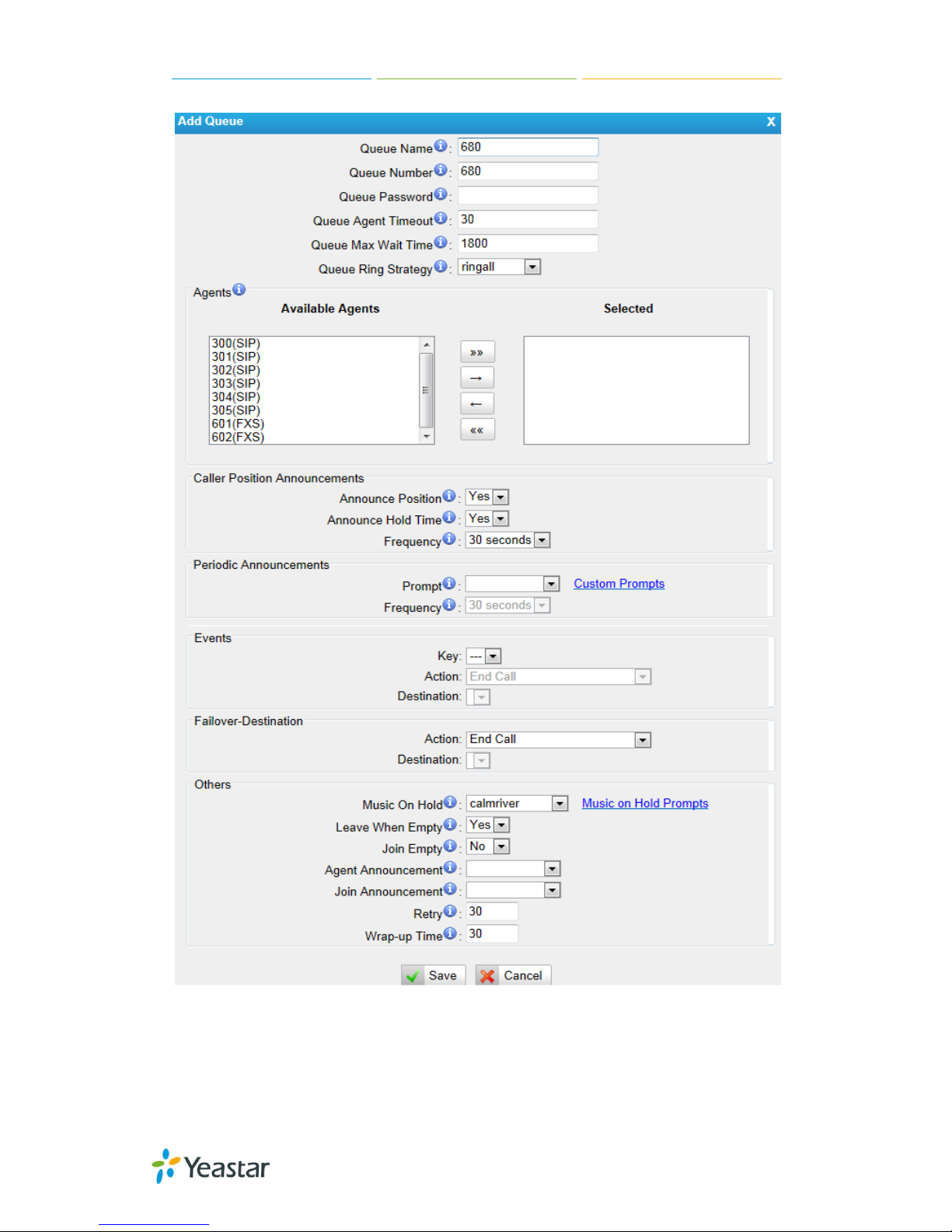
MyPBX U100/U200 Administrator Guide
92/195
Figure 6-43
·Queue Name
A name for the Queue.
Page 93

MyPBX U100/U200 Administrator Guide
93/195
·Queue Number
Use this number t o dial into the que ue, or transfer ca llers to this numbe r to put
them into the q ue ue .
·Queue Password
You can requi re agent s to enter a password b ef ore they can l ogin to thi s queue.
·Queue Agent Timeout
The number of second s a n a g e nt 's p hone c a n ring bef ore w e consid e r i t a
timeout.
·Queue Max Wait Time
The maximum number of second s a ca l le r can wait in a queu e before being
pulled out (0 for unlimited).
·Queue Ring Strategy
This option sets the Ringi ng S t ra t e g y f or t his Queue. T he op t ions are
RingAll
: Ring All available Agents simultaneously until one answers.
LeastRecent
: Ring the Agent which was least recently called.
FewestCalls
: Ring the Agent with the fewest completed calls.
Random
: Ring a Random Agent.
RRmemory
: Round Robin with Memory, Remembers where it left off in the last
ring pass".
1) Agents
This selection shows all users. Selecting a user here makes them a agent of the
current queue.
2) Caller Position Announcements
·Announce Position
Announce posit ion of caller i n t he q ue ue
·Announce Hold Time
Enabling thi s op t i on ca use s M yPBX t o a nnounce the hold t i me t o t he c a ll e r
periodically based on the frequency timer. Either yes or no; hold time will not be
announced if <1 minute.
·Frequency
How often to announce queue p osi t ion a nd estimate d hol d t ime .
Note: “0 seconds” means d is a b l e t he announcement.
3) Periodic Announcements
·Prompt
Select a prompt file to play periodically.
Page 94

MyPBX U100/U200 Administrator Guide
94/195
·Frequency
How often t o announce a prompt to t h e caller.
4) Events
If a caller presses the key while waiting in the queue, this setting selects which
action should process t he k ey p re ss.
5) Failover-Destination
Define the failover action. A failover occurs after the user reach the Queue max
wait time.
6) Others
·Music on Hold
Select the “Music on Hold” Class for this Queue.
·Leave When Empty
This option cont rols whe t her callers a l ready on hold are forced out of a q ue ue
that has no agents. There a re two opt i ons.
Yes: Callers are forced out of a queue when no agents are logged in.
No: Callers will remain in a queue with no agents.
·Join Empty
This option cont rols whe t her callers ca n j oin a call queue t ha t ha s no a g e nt s.
There are two options,
Yes: Callers can join a call queue with no agents or only unavailable ag ents
No: Callers cann ot j oin a queue with no ag e nt s
The default option is No.
·Agent Announcement
Announceme nt p l a ye d to the Agent p rior t o b ridg ing in the calle r.
·Join Announcement
Announceme nt p l a ye d to callers once prior to joining the q ue ue .
·Retry
The number of second s we w a it before trying all the phones again.
·Wrap-up time
How many seconds after the completion of a c all an Agent will have before the
Queue can ring the m wi t h a ne w c a ll . T he d e faul t is 30.
Page 95

MyPBX U100/U200 Administrator Guide
95/195
6.4.4 Conferences
Figure 6-44
Conference Calls increase employee efficiency and pr o ducti vity, and pr o vi de a
more cost-effective way to hold meetings. Conference agents can dial * to
access to the sett ings opti ons and the admin ca n kick the l ast user out a nd ca n
lock the conference room.
·Extension
This is the numbe r d ia l e d t o re a ch t hi s Conf e renc e Room.
·Admin
Admin can kick a use r out a nd can lock the conf e re nce roo m.
·Pin
Set a PIN that mu st be enter ed in order to a ccess th is con ference ro om (e.g.
1234).
Figure 6-45
Page 96

MyPBX U100/U200 Administrator Guide
96/195
6.4.5 Inbound Rou tes
Inbound routing processes incoming call tra ffic to destination extensions during
office hou rs or outside office hours
Figure 6-46
There is a defa ult inbound route for al l the trunks and set IVR as the desti nation,
you can edit it or create a new one for y our de mands or you can delete multiple
outbound routes at once as required. Whe n an incoming call arrives, t he system
will first check “fax detection”, then “Holidays”, at last “Business Days”.
Page 97

MyPBX U100/U200 Administrator Guide
97/195
Figure 6-47
1) General
·Route Name
A name for this in b ound rout e. E.g. “pstnin” etc.
·DID Number
Define the expected DID Number if this trunk passes DID on incoming calls.
Leave this field blank to match calls with any or no DID info. You can also use
pattern ma tching to match a rang e of numbe rs. The following patterns may be
used:
X: Any Digit from 0-9
Z: Any Digit from 1-9
Page 98

MyPBX U100/U200 Administrator Guide
98/195
N: Any Digit from 2-9
[12345-9]: Any digit in the brackets (in this example, 1, 2, 3, 4, 5, 6, 7, 8, 9)
The “.” Character will match any remaining digits. For example, “9011.” will
match any phone numb e r t ha t starts with “9011”, excluding “9011” itself.
The “!” will match none remaining digits, and causes the matching process to
complete as soon as it ca n b e determined that no other matches are possible.
Example 1: NXXXXXX will match any 7-digit phone number.
Example 2: 1NXXNXXXXX will match a phone number starting with a 1,
followed by a 3-digit area code, and then 6-digit number.
For more information, p l e a se refer to Appendix G How to Use DID
.
·Extension
Define the e xtension for DID numb er. This fi eld is only valid when you use B RI,
SIP, SPS or S PX trunk for this i nbound router. Y ou can only input n umber and “-”
in this field, and the format can be xxx or xxx-xxx. The count of the number
must be only one or eq ua l t he count of t he DID number.
·Caller ID Number
Define the Caller ID Number to be match ed o n in co m ing calls. L eave thi s field
blank to match any or no DID info.
You can also use a pattern match (e.g. 2[345]X) to match a range of numbers.
The following patterns may be used:
X: Any Digit from 0-9
Z: Any Digit from 1-9
N: Any Digit from 2-9
[12345-9] : Any digit in the brackets (in this example, 1,2,3,4,5,6,7,8,9)
The “.” Character will match any remaining digits. For example, “9011.” will
match any phone numb e r t ha t starts with “9011”, excluding “9011” itself.
The “!” will match none remaining digits, and causes the matching process to
complete as soon as it can be determined that no other matches are possible.
Example 1: NXXXXXX will ma t ch any 7 digit s p hone numb e r.
Example 2: 1NXXNXXXXX will match a phone number starting with a 1,
followed by a 3-digit area code, and then 6 digit number.
·Distinctive Ringtone
MyPBX support mapping to custom ring tone files. For example, if you configure
the distinctive ringing for custom ring tone to “Family”, the ring tone will be
played if the phone receives the incoming call.
·Enable Callback
You can enable t he ca l lback function of thi s i nb ound rout e . I f you want to
Page 99

MyPBX U100/U200 Administrator Guide
99/195
configure the callback function, please refer to chapter 6.7.4
How do I configure distinctive ring tones? Please refer to APPENDIX E
.
Currently distinctive ringtone can be compatible with Yealink and Snom phone.
2) Member Trunks
This area allows you to select which trunks will be member trunks for t his route.
To make a trunk a member of this route, please move it to the “Selected” box.
3) Business Days
Define where the calls will be routed during Business Days.
·Office Hours
Select one defined business days of f ice hours.
·Office Hours Destination
Configure whe re t o rout e t he i ncoming calls d uri ng of f i ce hours.
·End Calls
Route the incoming calls to end calls, the system will auto hang up the call.
·Extension
Route the incoming calls to a specific extension.
·Voicemail
Route the incomi ng calls to extension’s voice mail.
·IVR
Route the incoming calls to a specific IVR.
·Ring Group
Route the incoming calls to a specific Ring Group.
·Conference Room
Route the incoming call s to a sp e cif i c Confere nce Ro om.
·DISA
Route the incoming calls to a specific DISA.
·Queues
Route the incoming calls to a specific Queue.
·Faxes
Route the incoming fa xe s t o a sp eci f ic exte nsion’s mail a d d ress.
Page 100

MyPBX U100/U200 Administrator Guide
100/195
Note: This function only sup p orts T. 38 f a xe s.
·Outbound Route s
Route the incoming calls to a specific outbound route.
This function is ma inl y use d for the conne ction of two b ra nc he s.
For example: Comp a n y A loca t e s he adquarte rs in t he U S A w it h a b ra nch B i n
China. A and B both have MyPBX p hone systems.
Now if staff of A would like to make a call to a telephone or mobile phone in
China from the ext ension of A but via the FXS line of B, that can be done by this
configuration.
·Non-office Hours Destination
Configure whe re t o rout e t he i ncoming calls d uri ng non-office hours.
4) During Holidays
Define where the calls will be routed during Holidays.
·Holiday
Select which defined Holiday to use. When a time is de f in ed in both Business
Days and Holidays, it will be treated as Holidays.
·Destination
Configure whe re t o rout e t he i ncoming calls d uri ng holi d a y s.
5) Fax Detection
Configure if d e t e ct ing faxes in this inbound route.
Note: Please choose IVR as the destination above before configuring fax
detection (recommended).
·Destination
Configure where the faxes will be routed when faxes are detected.
·No detect
Do not detect faxes.
·Custom Email
Customize an E-mail address to receive the faxes. You should first configure
the “Voicemail Settings->SMTP Settings for Voicemail” correctly before you use
this option.
·Faxes
Send faxe s t o a n ext en sion. If choosing a F X S e xtension here, the fax will be
sent to the FXS port selected, you should connect a fax machine to this FXS port.
 Loading...