

YDI Wireless MB-HP Manual Marquee P P

Marquee Point-to-Point
Series
User Guide
Contact Terabeam
www.terabeam.com
8000 Lee Highway
Falls Church, VA 22042
Office: 703-205-0600
Fax: 703-205-0610
Sales: 1-888-297-9090
MNL-500274-001
Version 1.2
February 2005

Marquee™ Point-to-Point Series User Guide
LIMITED WARRANTY
Terabeam Wireless (Terabeam) warrants that your device is free of defects in material
and workmanship for a period of one year after initial purchase. Terabeam will, in this
period of time, repair or replace, any Terabeam product returned to the factory, freight
prepaid.
The Terabeam warranty covers repairs or replacement (at Terabeam’s option) of the
product only. Terabeam is not responsible for the cost of removal, reinstallation, or
shipping to the place of repair. Terabeam does not extend or modify its warranty period
as a result of repair or replacement.
Terabeam reserves the right to void a warranty and/or make reasonable charges for
repair of a unit if the warranty seal is broken or the unit displays evidence of misuse,
abuse, or tampering.
Terabeam is not responsible for damage to any other equipment or property, or any other
consequential or incidental damages of any kind, whether based on contract, negligence,
or strict liability. Maximum liability shall not in any case exceed the purchase price of the
unit.
Warranties give you (the buyer) specific legal rights. You may also have other rights that
vary from state to state. This warranty is only extended to purchases made in the United
States of America or its possessions.
SPECIAL WARRANTY NOTICE
The warranty is null and void if any of the following occurs:
1. The product enclosure is opened.
2. The connections are not properly waterproofed.
3. The device is installed improperly or with incorrect connectors.
4. The round connector of the outdoor Ethernet cable (if provided) is improperly
plugged into the rear jack of the enclosure.
5. The device or DC Power Injector (if provided) are physically damaged.
6. The device is operated outside the recommended DC power specifications.
7. The device is damaged by extreme forces of nature, lightning, or ‘Acts of God.’
FCC NOTICE
This device complies with part 15 of the FCC rules. Operation is subject to the following two
conditions:
1. This device may not cause harmful interference, and
2. This device must accept any interference received, including interference that may cause
undesired operation.
* Note: The manufacturer is not responsible for any radio or TV interference caused by
unauthorized modifications to this equipment. Such modifications could void the user' s
authority to operate the equipment.
These products are labeled with one of the following FCC ID numbers:
FCC ID: NM5-MB-HP, NM5-MB-49, NM5-MB-49-HP
Version 1.2 Page i February 2005

Marquee™ Point-to-Point Series User Guide
TABLE OF CONTENTS
Section 1 Overview 1
1.1 Description....................................................................................................................................1
1.2 Marquee Kit Contents ...................................................................................................................2
Section 2 Installation 3
2.1 Introduction ...................................................................................................................................3
2.2 DC Power Injector.........................................................................................................................3
2.3 Power Supply................................................................................................................................3
2.4 LEDs..............................................................................................................................................3
2.5 Hardware Installation – FP Enclosure...........................................................................................4
2.6 Hardware Installation – EX Enclosure ..........................................................................................6
2.7 Cabling the Marquee (All Enclosures)..........................................................................................8
2.8 Antenna Alignment......................................................................................................................10
Section 3 Configuration 15
3.1 Installing the Management Software...........................................................................................15
3.2 Using the Configurator................................................................................................................15
3.3 Configuring the Marquee.............................................................................................................16
Appendix A – Marquee Technical Specifications 19
© 2005 Terabeam Wireless. All Rights Reserved. No part or parts of this document may be
reproduced, translated, stored in any electronic retrieval system or transmitted, in any form or by any
means, electronic, mechanical, photocopied, recorded or otherwise, without the prior written
permission of Terabeam Wireless.
The information in this document is subject to change without notice. Although every effort has been
made to make this manual accurate and complete, Terabeam Wireless assum es no responsibility for
any errors that may appear in this document.
Version 1.2 Page ii February 2005

Marquee™ Point-to-Point Series User Guide
Section 1 Overview
1.1 Description
The Marquee™ Series is a powerful answer for customers seeking a reliable high-speed wireless
connectivity solution. It provides the best features and wireless reach in the field by combining industry
leading outdoor point-to-point (P-P) optimized software with its patented amplifier technology. Unlike
other single band products, Marquee gives you the choice of installing a license-free 5.8 GHz, or a
licensed 4.9 GHz network. If your needs change in the future, Marquee can change with you.
The Marquee P-P Series is comprised of Marquee Bridges. The Marquee is available in two types of
enclosures: a flat panel (FP) and a ruggedized (EX) enclosure (see Figures 1.1a and b). The FP
enclosure features a 23 dBi integrated antenna. The EX enclosure comes either with a 23 dBi flat panel
antenna attached to the top of the unit, or it has an N-type connector on the rear to plug an external
antenna. Table 1.1 shows the possible combinations of Marquee products, solutions and antennas that
are offered. Refer to Appendix A for Marquee technical specifications.
Table 1.1 – Marquee P-P Series and Antenna Combinations
Enclosure Type of Marquee Type of Antenna Model Number
Ordered separately
MPP49SEXN
MPP49HEXN
FP Attached (23 dBi) MPP58HEX23A
Ruggedized (EX)2Bridge
Dish 2 ft (28 dBi) MPP58HEX28D
1
Dish 2.5 ft (31 dBi) MPP58HEX31D
Dish 3 ft (34 dBi) MPP58HEX34D
Flat panel (FP) Bridge FP Integrated (23 dBi) MPP58HFP23I
1 49 = 4.9 GHz S = Standard (Non-Amplified)
58 = 5.8 GHz H = High Power (Amplified)
2
Models with external antennas include one 6 ft LMR-600 coax cable per unit
Version 1.2 Page 1 February 2005
Marquee™ Point-to-Point Series User Guide
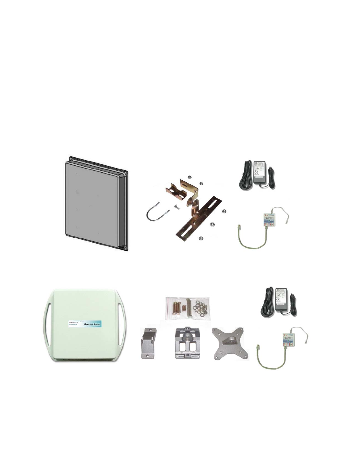
1.2 Marquee Kit Contents
Each Marquee kit includes the following (refer to Figures 1.1a and b):
• Outdoor radio with mounting hardware (two each)
• Surge protected Cat 5 DC Power Injector (two each)
• 110/240 VAC to 48 VDC power supply (two each)
• CD-ROM with Windows-based Configurator software
• User’s Manual
A Terabeam outdoor Ethernet cable must be ordered separately per unit. Available lengths are 50, 100,
200, or 300 feet.
Figure 1.1a – Components of Marquee FP Enclosure
(Two Each for a Marquee Bridge P-P Configuration)
Figure 1.1b – Components of Marquee EX Enclosure
(Two Each for a Marquee Bridge P-P Configuration
Version 1.2 Page 2 February 2005
Marquee™ Point-to-Point Series User Guide
Section 2
Installation
CAUTION
This equipment complies with FCC radiation exposure limits set forth for
an uncontrolled environment when installed as directed. The equipment
should be installed and operated outdoors with fix-mounted antennas
such that there will be a minimum of 2 meters of separation distance
between the antenna and all persons during normal operation. This
includes integrated, attached and external antenna versions of
equipment. If you are using dish antennas, the minimum separation
distance must be 2.56 meters.
2.1 Introduction
The Marquee is intended for professional installation only. Please review the entire manual before
powering up or deploying these units.
NOTE: It is strongly recommended that you configure and test the units prior to deploying them in the
field. Set up a “mini-network” that resembles your actual configuration as close as possi ble.
By using such a mock-up, troubleshooting potential problems will be much easier than if you
already installed the equipment in the field. Read through this entire Section 2 to understand
how to install the hardware. To configure the Marquee, read Section 3.
Safety Warning
2.2 DC Power Injector
The Cat 5 DC Power Injector is not in a waterproof enclosure and must be protected from the weather. It
can be permanently mounted to a surface using the double stick tape found on the back of it.
2.3 Power Supply
The Marquee kit comes with a 110/220 VAC to 48 VDC power supply that has a standard ba rrel plug
[center pin positive (+) tip and outer ring negative (-)].
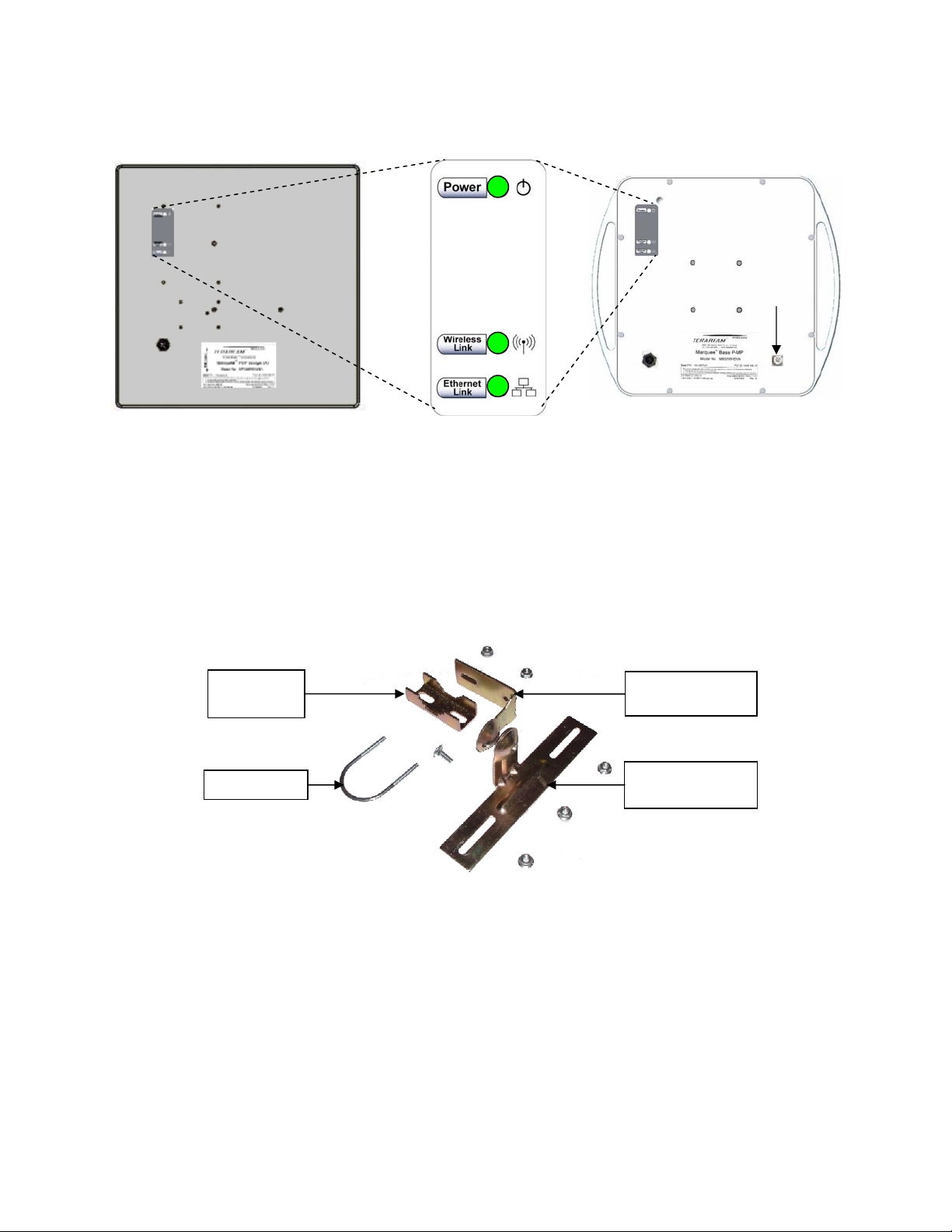
2.4 LEDs
Three LEDs are present on the back of the Marquee (see Figures 2.1a and b):
• The green Power LED stays on when the unit is plugged and operating correctly
• The green Wireless Link LED flashes when there is traffic over the wireless medium
• The green Ethernet Link LED flashes when there is traffic over the Ethernet port
Version 1.2 Page 3 February 2005
Marquee™ Point-to-Point Series User Guide
(B)
Figure 2.1 – Marquee LEDs
(a) Flat Panel (FP) Version (b) Ruggedized (EX) Version
N-Type
Connector
for External
Antenna
2.5 Hardware Installation – FP Enclosure
: d with all-weather electrical tape, Permagum, or
NOTE All connectors must be properly water-proofe
equivalent. Do not use Silicon glue.
he Marque mounting bracket (A) that is secured to the pole with a
pivot adaptor bracket (B), a pole clamp (C), and a U-bolt (D). Figure 2.2 shows the hardware provided to
mount the Marquee FP unit.
e FP unit is installed by using a pole T
Figure 2.2 – Marquee FP Mounting Hardware
Pole
Clamp (C)
U-Bolt (D)
Pivot Adaptor
Bracket
Pole Mounting
Bracket (A)
he integrated antenna can be mounted either vertically or horizontally polarized. The label located on T
the back of the unit contains an arrow indicating the antenna’s polarization (see Figures 2.3a and b).
Please note that both ends of the link must use the same polarization. Be aware that most omni
antennas are vertically polarized and if the Marquee FP is aimed at one, it must be installed vertically
polarized, i.e., with the polarization arrow up and down.
Version 1.2 Page 4 February 2005
Marquee™ Point-to-Point Series User Guide
r
Figure 2.3 – Marquee FP Orientation
(a) For Vertical Polarization (b) For Horizontal Polarization
(A)(A)
Circula
Tab
Polarization
Arrow
Polarization
Arrow
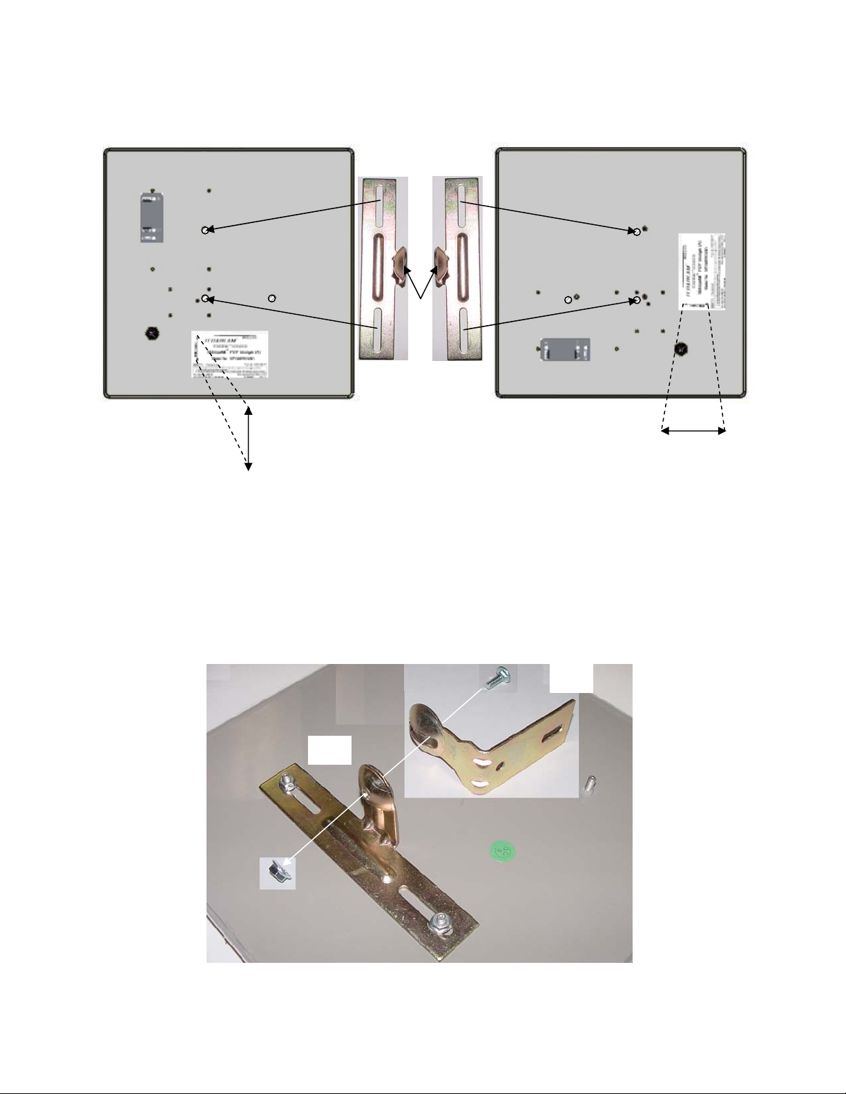
1. Fit the pole mounting bracket (A) to the two studs protruding from the back of the Marquee FP unit
according to the desired polarization, as shown in Figures 2.3a and b. Position the bracket so that the
side that has the circular tab is pointing towards the center of the unit. Secure to the unit by threading
two nuts and tighten them firmly with an appropriate wrench.
2. Attach the pivot adaptor bracket (B) to the pole mounting bracket (A) by using bolt and nut, as shown
in Fig 2.4. Tighten hardware (one place). IMPORTANT: Ensure that convex edge of the pivot adaptor
bracket (B) is facing concave edge of the pole mounting bracket (A).
Figure 2.4 –Assembly of Pivot Adaptor Bracket (B) to Pole Mounting Bracket (A)
(B)
(A)
Version 1.2 Page 5 February 2005
 Loading...