

Page 1

Marquee Point-to-MultiPoint
Series
User Guide
Contact Terabeam
www.terabeam.com
8000 Lee Highway
Falls Church, VA 22042
Office: 703-205-0600
Fax: 703-205-0610
Sales: 1-888-297-9090
MNL-500273-001
Version 1.3(a)
Jul 2005
Page 2

Marquee™ Point-to-MultiPoint Series User Guide
LIMITED WARRANTY
Terabeam Wireless (Terabeam) warrants that your device is free of defects in material
and workmanship for a period of one year after initial purchase. Terabeam will, in this
period of time, repair or replace, any Terabeam product returned to the factory, freight
prepaid.
The Terabeam warranty covers repairs or replacement (at Terabeam’s option) of the
product only. Terabeam is not responsible for the cost of removal, reinstallation, or
shipping to the place of repair. Terabeam does not extend or modify its warranty period
as a result of repair or replacement.
Terabeam reserves the right to void a warranty and/or make reasonable charges for
repair of a unit if the warranty seal is broken or the unit displays evidence of misuse,
abuse, or tampering.
Terabeam is not responsible for damage to any other equipment or property, or any other
consequential or incidental damages of any kind, whether based on contract, negligence,
or strict liability. Maximum liability shall not in any case exceed the purchase price of the
unit.
Warranties give you (the buyer) specific legal rights. You may also have other rights that
vary from state to state. This warranty is only extended to purchases made in the United
States of America or its possessions.
SPECIAL WARRANTY NOTICE
The warranty is null and void if any of the following occurs:
1. The product enclosure is opened.
2. The connections are not properly waterproofed.
3. The device is installed improperly or with incorrect connectors.
4. The round connector of the outdoor Ethernet cable (if provided) is improperly
plugged into the rear jack of the enclosure.
5. The device or DC Power Injector (if provided) are physically damaged.
6. The device is operated outside the recommended DC power specifications.
7. The device is damaged by extreme forces of nature, lightning, or ‘Acts of God.’
FCC NOTICE
This device complies with part 15 of the FCC rules. Operation is subject to the following two
conditions:
1. This device may not cause harmful interference, and
2. This device must accept any interference received, including interference that may cause
undesired operation.
* Note: The manufacturer is not responsible for any radio or TV interference caused by
unauthorized modifications to this equipment. Such modifications could void the user' s
authority to operate the equipment.
These products are labeled with one of the following FCC ID numbers:
FCC ID: NM5-MB-HP, NM5-MB-49, NM5-MB-49-HP
Version 1.3(a) Page i Jul 2005
Page 3

Marquee™ Point-to-MultiPoint Series User Guide
TABLE OF CONTENTS
Section 1 Overview 1
1.1 Description....................................................................................................................................1
1.2 Marquee P-MP Kit Contents.........................................................................................................1
Section 2 Installation 3
2.1 Introduction ...................................................................................................................................3
2.2 DC Power Injector.........................................................................................................................3
2.3 Power Supply................................................................................................................................3
2.4 LEDs..............................................................................................................................................3
2.5 Hardware Installation – FP Enclosure...........................................................................................4
2.6 Hardware Installation – EX Enclosure ..........................................................................................6
2.7 Cabling the Marquee P-MP (All Enclosures)................................................................................8
2.8 Antenna Alignment......................................................................................................................10
Section 3 Configuration 15
3.1 Installing the Configurator...........................................................................................................15
3.2 Basic Configuration of a Marquee P-MP.....................................................................................15
Section 4 Troubleshooting 20
4.1 Introduction .................................................................................................................................20
4.2 Cabling or Installation Issues......................................................................................................20
4.3 Configuration Issues ...................................................................................................................21
4.4 When to Contact Technical Support...........................................................................................23
Appendix A – Marquee P-MP Technical Specifications 24
PROFESSIONAL INSTALLATION REQUIRED
The Marquee P-P must be installed as a system by experienced antenna installation
professionals who are familiar with Radio Frequency (RF) issues such as gains and
losses, as well as local building and safety codes. Failure to do so will void the product
warranty and may expose the end user to excessive RF hazard.
Regulations regarding maximum antenna gains, power output and maximum permissible
exposure vary from country to country. It is the responsibility of the end user to operate
within the limits of these regulations and to ensure that the professional installers who
install this device are aware of these regulations. All antennas are intended to be installed
outdoors.
© 2005 Terabeam Wireless. All Rights Reserved. No part or parts of this document may be
reproduced, translated, stored in any electronic retrieval system or transmitted, in any form or by any
means, electronic, mechanical, photocopied, recorded or otherwise, without the prior written
permission of Terabeam Wireless.
The information in this document is subject to change without notice. Although every effort has been
made to make this manual accurate and complete, Terabeam Wireless assum es no responsibility for
any errors that may appear in this document.
The Terabeam Wireless logo is a trademark of Terabeam Wireless, Inc. Marquee is a trademark of
Terabeam Wireless, Inc. TurboCell is a registered trademark of Terabeam Wireless, Inc. All other
trademarks in this document are the property of their respective owners.
Version 1.3(a) Page ii Jul 2005
Page 4

Marquee™ Point-to-MultiPoint Series User Guide
Section 1 Overview
1.1 Description
The Marquee™ Point-to-MultiPoint (P-MP) Series is a powerful answer for customers seeking a reliable
high-speed wireless connectivity solution. It provides the best features and wireless reach in the field by
combining industry leading outdoor Point-to-MultiPoint optimized software with its patented amplifier
technology. Unlike other single band products, Marquee gives you the choice of installing a license-free
5.8 GHz, or a licensed 4.9 GHz network. If your needs change in the future, Marquee can change with
you.
The Marquee P-MP Series features the award-winning industry standard TurboCell
which significantly enhances the performance of outdoor 802.11 systems through the use of adaptive
dynamic polling, bandwidth allocation at the client, and packet aggregation. TurboCell
node” problem inherent in adding nodes to traditional 802.11 outdoor networks.
Marquee P-MP Series is comprised of Marquee Base units and Marquee Client / Cu stomer Premise
Equipment (CPE) units, also called Remote or Satellite units. The Marquee Base and Satellites are
available in two types of enclosures: a flat panel (FP) and a ruggedized (EX) enclosure (see Figures 1.1a
and b). The FP enclosure features an integrated antenna. The EX enclosure comes eithe r with a flat
panel antenna attached to the top of the unit, or it has an N-type connector on the rear to plug an external
antenna.
Refer to Appendix A for Marquee P-MP technical specifications.
®
software, a protocol
®
1
solves the “hidden
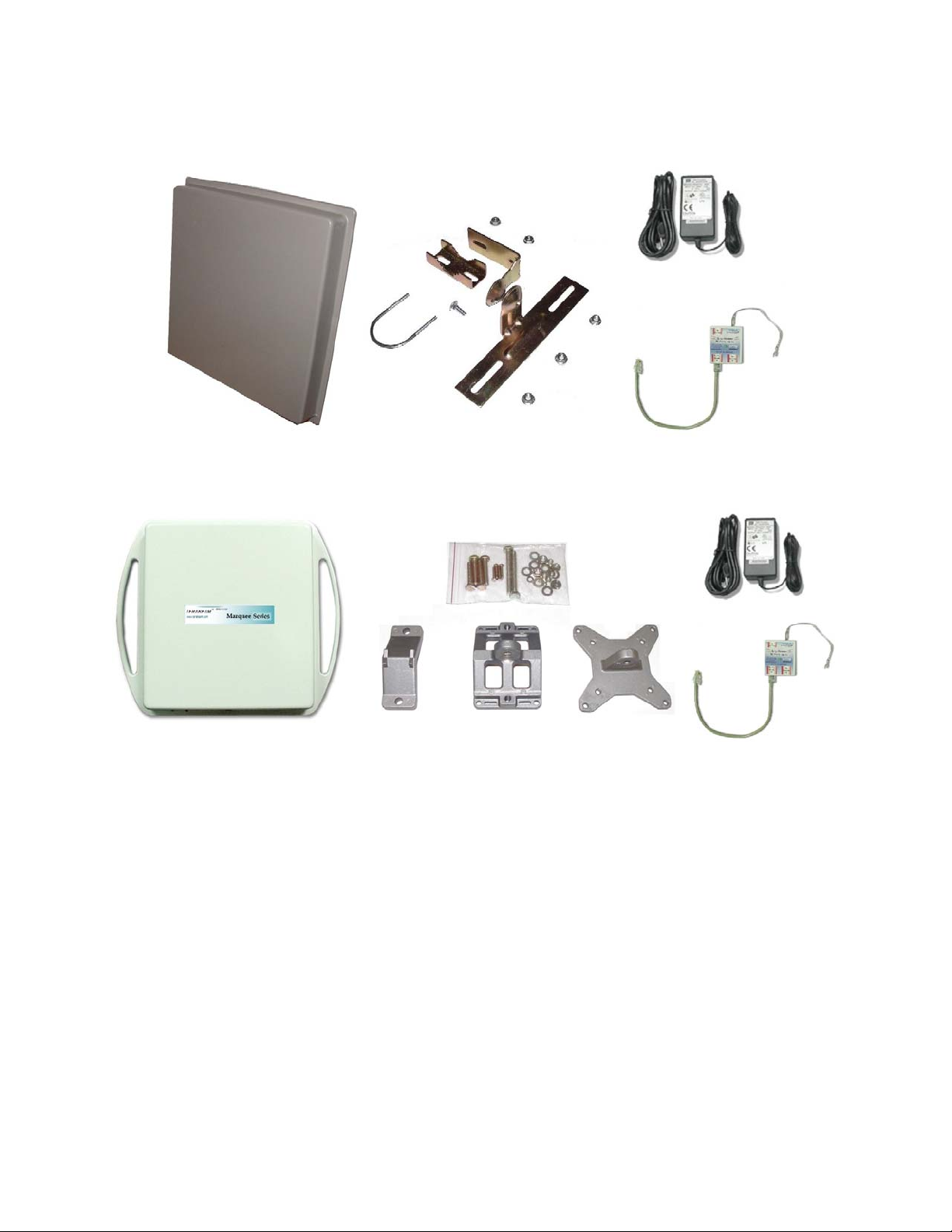
1.2 Marquee P-MP Kit Contents
Each Marquee P-MP kit includes the following (refer to Figures 1.1a and b):
• Outdoor radio with mounting hardware
• Surge protected Cat 5 DC Power Injector
• 110/240 VAC to 48 VDC power supply
• CD-ROM with Windows-based Configurator software
• User’s Manual
A Terabeam outdoor Ethernet cable must be ordered separately per unit. Available lengths are 50, 100,
200, or 300 feet. Models with external antennas include one 6 ft LMR-600 coax cable per unit.
1 Marquee 1.0 P-MP units operating with TurboCell® do not support traditional 802.11 Base station or Client access.
Version 1.3(a) Page 1 Jul 2005
Page 5
Marquee™ Point-to-MultiPoint Series User Guide
Figure 1.1a – Components of Marquee P-MP FP Enclosure
Figure 1.1b – Components of Marquee P-MP EX Enclosure
Version 1.3(a) Page 2 Jul 2005
Page 6
Marquee™ Point-to-MultiPoint Series User Guide
Section 2
Installation
CAUTION
This equipment complies with FCC radiation exposure limits set forth for
an uncontrolled environment when installed as directed. The equipment
should be installed and operated outdoors with fix-mounted antennas
such that there will be a minimum of 2 meters of separation distance
between the antenna and all persons during normal operation. This
includes integrated, attached and external antenna versions of
equipment.
2.1 Introduction
The Marquee P-MP is intended for professional installation only. Please review the entire manual before
powering up or deploying these units.
NOTE: It is strongly recommended that you configure and test the units prior to deploying them in the
field. Set up a “mini-network” that resembles your actual configuration as close as possi ble.
By using such a mock-up, troubleshooting potential problems will be much easier than if you
already installed the equipment in the field. Read through this entire Section 2 to understand
how to install the hardware. To configure the Marquee P-MP, read Section 3.
Safety Warning
2.2 DC Power Injector
The Cat 5 DC Power Injector is not in a waterproof enclosure and must be protected from the weather. It
can be permanently mounted to a surface using the double stick tape found on the back of it.
2.3 Power Supply
The Marquee P-MP kit comes with a 110/220 VAC to 48 VDC power supply that has a standard barrel
plug [center pin positive (+) tip and outer ring negative (-)].
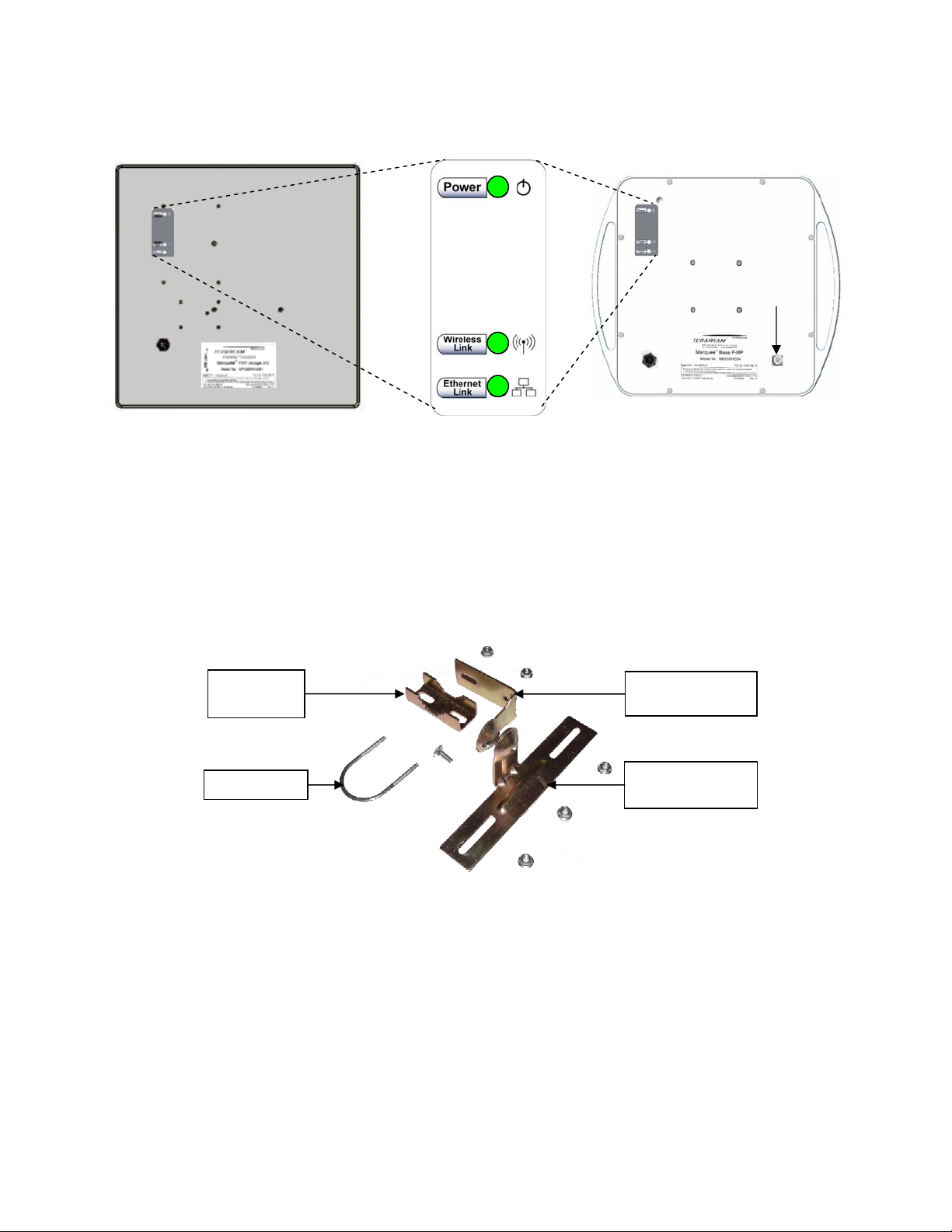
2.4 LEDs
Three LEDs are present on the back of the Marquee (see Figures 2.1a and b):
• The green Power LED stays on when the unit is plugged and operating correctly
• The green Wireless Link LED flashes when there is traffic over the wireless medium
• The green Ethernet Link LED flashes when there is traffic over the Ethernet port
Version 1.3(a) Page 3 Jul 2005
Page 7
Marquee™ Point-to-MultiPoint Series User Guide
(B)
Figure 2.1 – Marquee P-MP LEDs
(a) Flat Panel (FP) Version (b) Ruggedized (EX) Version
N-Type
Connector
for External
Antenna
2.5 Hardware Installation – FP Enclosure
: d with all-weather electrical tape, Permagum, or
NOTE All connectors must be properly water-proofe
equivalent. Do not use Silicon glue.
he Marque pole mounting bracket (A) that is secured to the pole
with a pivot adaptor bracket (B), a pole clamp (C), and a U-bolt (D). Figure 2.2 shows the hardware
provided to mount the Marquee P-MP FP unit.
e P-MP FP unit is installed by using aT
Figure 2.2 – Marquee P-M
Pole
Clamp (C)
U-Bolt (D)
P FP Mounting Hardware
Pivot Adaptor
Pole Mounting
Bracket
Bracket (A)
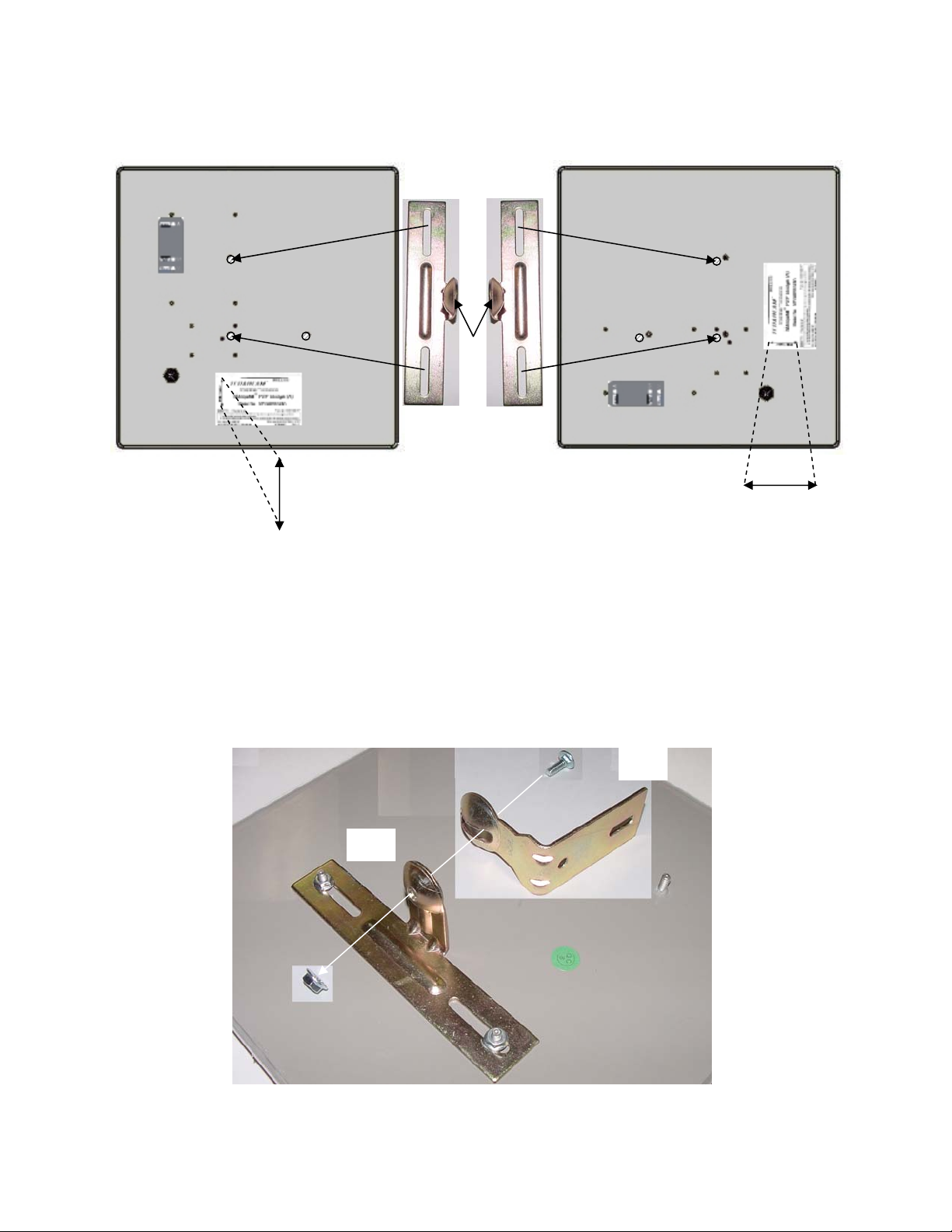
he integrated antenna can be mounted either vertically or horizontally polarized. The label located on T
the back of the unit contains an arrow indicating the antenna’s polarization (see Figures 2.3a and b).
Please note that both ends of the link must use the same polarization. Be aware that most omni
antennas are vertically polarized and if the Marquee P-MP FP is aimed at one, it must be installed
vertically polarized, i.e., with the polarization arrow up and down.
Version 1.3(a) Page 4 Jul 2005
Page 8
Marquee™ Point-to-MultiPoint Series User Guide
r
Figure 2.3 – Marquee P-MP FP Orientation
(a) For Vertical Polarization (b) For Horizontal Polarization
(A)(A)
Circula
Tab
Polarization
Arrow
Polarization
Arrow
1. Fit the pole mounting bracket (A) to the two studs protruding from the back of the Marquee P-MP FP
unit according to the desired polarization, as shown in Figures 2.3a and b. Position the bracket so that
the side that has the circular tab is pointing towards the center of the unit. Secure to the unit by
threading two nuts and tighten them firmly with an appropriate wrench.
2. Attach the pivot adaptor bracket (B) to the pole mounting bracket (A) by using bolt and nut, as shown
in Fig 2.4. Tighten hardware (one place). IMPORTANT: Ensure that convex edge of the pivot adaptor
bracket (B) is facing concave edge of the pole mounting bracket (A).
Figure 2.4 –Assembly of Pivot Adaptor Bracket (B) to Pole Mounting Bracket (A)
(B)
(A)
Version 1.3(a) Page 5 Jul 2005
Page 9

Marquee™ Point-to-MultiPoint Series User Guide
3. Turn the pivot adaptor bracket (B) so that the rectangular part is parallel with the surface of the
Marquee P-MP FP. Fasten the Marquee P-MP unit to the pole using pole clamp (C), U-bolt (D), and
two nuts, as shown in Fig 2.5. Tighten hardware (two places). The pole clamp (C) and U-bolt (D) will
accept pole diameters between 0.75” to 1.5” OD.
Figure 2.5 – Attaching the Marquee P-MP FP Unit to the Pole
(A)
Max 1.5”
(C)
Min 0.75”
(D)
(B)
Proceed to Section 2.7 – Cabling the Marquee P-MP (All Enclosures).
2.6 Hardware Installation – EX Enclosure
NOTE: All connecto rs must be properly water-proofed with all-weather electrical tape, Permagum, or
equivalent. Do not use Silicon glue.
The Marquee P-MP EX unit is installed by using an “X”-shaped adaptor bracket (A) that is secured to the
pole with a pole mounting bracket (B), and a pole clamp (C). Figure 2.6 shows the hardware provided to
mount the Marquee P-MP EX unit.
Figure 2.6 – Marquee P-MP EX Mounting Hardware
Hardware Qty
Screw Hex Head M5x20 4
Arm (For indoor
installations only,
not used)
Pole Clamp (C)
(for TeraBridge 5x45 only)
Screw Hex Head M8x40 4
(for poles between 1” to 1.75” OD)
Screw Hex Head M8x70 2
(for poles between 1.75” to 3” OD)
Lock Washer M5 (with a cut) 4
Flat Washer M5 (solid) 4
Nut M5 4
Lock Washer M8 (with a cut) 4
Flat Washer M8 (solid) 6
Nut M8 2
“X”-Shaped Adaptor
Bracket (A)
Pole Mounting
Bracket (B)
Version 1.3(a) Page 6 Jul 2005
Page 10

Marquee™ Point-to-MultiPoint Series User Guide
The antenna can be mounted either vertically or horizontally polarized. If you are using a Marquee P-MP
with an attached antenna, the label located on the back of the unit shows an arrow indicating the
antenna’s polarization (see Figures 2.7a and b). Please note that both ends of the link must use the
same polarization. Be aware that most omni antennas are vertically polarized and if the Marquee P-MP
EX is aimed at one, it must be installed vertically polarized, i.e., with the polarization arrow up and down.
If you are using a Marquee P-MP with an external antenna, there is no arrow on the label located on the
back of the unit and an additional N-type female jack is present to connect a short coax cable to the
antenna (see Figure 2.1b). All previous considerations regarding polarization are applicable to the
external antenna.
If you are using a Marquee P-MP with an external antenna, the unit must
be operated with a proper antenna, microwave load or terminator
WARNING
plugged into the N-type female jack on the back of the unit. Operating
the Marquee P-MP with nothing connected to the jack may result in
damage to the TX section of the unit which will not be covered by the
factory warranty and will be a billable repair.
Figure 2.7 – Marquee P-MP EX With Attached Antenna Orientation
(a) For Vertical Polarization (b) For Horizontal Polarization
Polarization
Arrow
Polarization
Arrow
1. Fit the adaptor bracket (A) to the four studs protruding from the back of the Marquee P-MP EX unit, by
aligning the four inner
holes with the mounting studs on the back of the unit and securing to the unit
using four nuts, lock washers, and flat washers, as shown in Figure 2.8. Tighten hardware (four
places). IMPORTANT: Note the position of the serrated edge of bracket (A).
Attach the pole mounting bracket (B) to adaptor bracket (A) by using one M8x
. 40 bolt and flat washer
2
on one side, and nut, lock washer and flat washer on the other, as shown in Fig 2.8. Tighten hardware
(one place). IMPORTANT: Ensure that the serrated edges on both brackets are facing each other.
. s,
Fasten the unit to the pole using pole clamp (C) and two M8x70 bolts, lock washers, and flat washer3
as shown in Fig 2.9. Tighten hardware (two places). The pole mounting bracket (B) will accept pole
diameters between 1.75” to 3” OD. You may attach the Marquee P-MP unit to smaller diameter poles,
between 1” to 1.75” OD, by flipping over the pole clamp (C) so the convex part faces the pole and
using two M8x40 bolts. The Marquee P-MP unit can also be mounted to larger pole diameters by
Version 1.3(a) Page 7 Jul 2005
Page 11

Marquee™ Point-to-MultiPoint Series User Guide
A
discarding pole clamp (C) and replacing it with metal straps (not included) fastened through slots
located on the pole mounting bracket (B).
Figure 2.8 – Detail Showing Assembly of Pole Mounting Bracket to Marquee P-MP EX
B
Serrated Edges
Figure 2.9 – Attaching the Marquee P-MP EX Unit to the Pole
Slots for optional
metal straps
C
Max 3.0”
Min 1.0”
Proceed to Section 2.7 – Cabling the Marquee P-MP (All Enclosures).
2.7 Cabling the Marquee P-MP (All Enclosures)
1. Ensuring that there is no DC power applied to the cable, plug the 6-pin N-male round connector of the
outdoor Ethernet cable (ordered separately) into the rear jack of the unit, making sure the notch on
the connector is correctly aligned with the tab on the jack as shown on Figure 2.10. Turn the round
locking nut clockwise as you push in until it securely fastens onto the jack. Please verify that the
round connector is properly plugged into the rear jack of the antenn a prior to connecting DC
power because it is possible to push it in the wrong way if enough force is used. If DC power is
applied and the connector is not properly plugged, damage to the electronics of the unit or the
connector itself may occur which will not be covered by the factory warranty.
Version 1.3(a) Page 8 Jul 2005
Page 12

Marquee™ Point-to-MultiPoint Series User Guide
plugging
If DC Power is applied while you are attempting to insert the round
connector into the jack, it is possible that, as you rotate the plug in an
effort to find the key, DC power pins will momentarily touch the Ethernet
WARNING
pins. If this happens the Ethernet circuitry on the board will be
damaged. Also, do not apply excessive pressure when you insert the
round connector or the pins will pop out. Any damage caused by this
action will not
be covered by the factory warranty and will be a billable
repair.
Figure 2.10 – Plugging the Outdoor Ethernet Cable
Plug the connector into the jack by
aligning the notch with the tab
Caution: Be sure DC Power is not applied
when
the cable
2. Attach the other end of the outdoor Ethernet cable to the Cat 5 DC Power Injector at port RJ-45
labeled “To Antenna.”
3. Connect the Ethernet cable labeled “To PC/Router” from the Cat 5 DC Power Injector into a regular
port on your router, switch or hub. If you connect to a laptop or PC, use a cross-over cable or adapter.
4. Perform an Earth ground connection to any of the rear bolts of the unit, the mounting brackets, or the
mast (if metallic). For maximum protection, also connect the metal wire of the surge protected DC
Injector to ground as shown on Figure 2.11.
Figure 2.11 – Installation of the Terabeam Surge Protected DC Injector
for Maximum Grounding Protection
AC Pow er
Power Supply
RJ-45 Ethernet Connector
To Switch, Router or PC
Surge Protected
DC Injector
Ground Wire
To Marquee
5. If you are using a Marquee P-MP unit with an external antenna, connect the antenna to the N-type
female jack on the back of the unit.
6. Connect the barrel plug of the power supply to the “DC Power” jack on the Cat 5 DC Power Injector,
then plug the Power Supply into an AC outlet. Check that the green Power LED on the Marquee
Version 1.3(a) Page 9 Jul 2005
Page 13

Marquee™ Point-to-MultiPoint Series User Guide
P-MP turns on. If there is traffic over the wireless medium the green Wireless Link LED should be
flashing. If the Ethernet port is active the green Ethernet Link LED should be flashing.
7. Install the Configurator program on a laptop or PC and configure your system (see Section 3). You
are going to use the antenna alignment and link monitoring screen of the program to align the
antennas.
2.8 Antenna Alignment
There are three possible antennas that you can use with the Marquee P-MP unit:
• An FP enclosure
• An EX enclosure with an attached antenna
• An external antenna
The purpose of the following steps is to adjust the Line-of-Sight (LOS) of the antennas in order to
maximize the main lobe Signal-to-Noise Ratio (SNR) level. Regardless of the type of antenna that you
are using, the procedure involves making an azimuth (horizontal) alignment and an elevation (vertical)
alignment. The steps below pertain to integrated and attached antennas, but they are also applicable to
external antennas as long as you follow the specific alignment instructions of the corresponding
manufacturer. For a P-MP configuration there are two possible cases:
• If you are installing a P-MP configuration for the first time, you are going to align both the antenna
at the Base site and the antenna at the CPE site.
• If you are installing a new Client in an existing P-MP configuration, you are going to align only the
antenna at the new CPE site.
IMPORTANT: During this process, all Marquee P-MP units must be at the same stage of the installation
procedure and powered ON. It is assumed that you have configured your units (see Section 3) and that
there is communication between the Configurator program and your Marquee P-MP units. Unless
specifically noted, the term “antenna” is used to describe either of the three types.
1. Perform a coarse alignment of the antenna by using a compass heading so it is roughly “looking” at its
remote partner.
2. Connect the near end Marquee P-MP unit to the laptop or PC where the Configurator program is
installed by using a crossover Ethernet cable. Run the Configurator. Verify that the unit where you are
locally connected to as well as its remote partner are both displayed on the Main Screen (Fig. 2.12).
Note: If you cannot see the partner Marquee P-MP unit on the Main Screen, that probably means
that your antenna is so misaligned that it cannot link to its partner. If you are setting a new PMP configuration, perform a coarse alignment of both antennas by using a compass heading
so they are “looking” at each other. Place the cursor anywhere in the List of Scanned
Devices box and right-click the mouse. A Re-scan local network button will appear. Click on
the button. If the partner Marquee P-MP still does not appear, repeat these steps until it is
displayed. If you are installing a new client on an existing P-MP configuration, only align the
Client antenna. The Base station antenna should not
3. Click the Analyze tab, then click the Wireless Link Test button. The Enter IP Address window
appears (Fig. 2.13). Enter the IP address of the local unit (in this case 198.17.74.253) and a password
of public (unless you have previously changed it, then enter the one you defined). Click OK.
be touched.
Version 1.3(a) Page 10 Jul 2005
Page 14

Marquee™ Point-to-MultiPoint Series User Guide
Figure 2.12 – Configurator Main Screen
Local Marquee
Remote Marquee
Figure 2.13 –Enter IP Address Screen
4. The Select a Remote Link Partner window appears (Figure 2.14). Verify that you have the partner
Marquee P-MP unit displayed in the box, click on it and then click the Link Test button (or doubleclick the partner unit). The Remote Test Link window is shown (Figure 2.15). The main goal now is to
peak the SNR levels at both ends of the link.
Version 1.3(a) Page 11 Jul 2005
Page 15

Marquee™ Point-to-MultiPoint Series User Guide
Figure 2.14 – Select a Remote Link Partner Screen
Remote Marquee
Figure 2.15 – Remote Link Test Screen
Maximize these levels
5. Using the Azimuth adjustment bolts (see Figure 2.16a or b), adjust the azimuth until the SNR readings
for both ends of the link peak. Start with azimuth adjustment on the far end of the link first (if
applicable). It is recommended that, in order to ensure the true maximum, you should adjust through
the maximum SNR reading until the reading clearly drops and continues to drop to lower level sidelobes. Adjust back until the maximum is attained again. Then repeat for the near end of the link.
6. Using the Elevation adjustment bolt (see Figure 2.16a or b), adjust the elevation until the SNR
readings for both ends of the link peak. Start with elevation adjustment on the far end of the link first (if
applicable). It is recommended that, in order to ensure the true maximum, you should adjust through
the maximum SNR reading until the reading clearly drops and continues to drop to lower level sidelobes. Adjust back until the maximum is again attained. Then repeat for the near end of the link.
Version 1.3(a) Page 12 Jul 2005
Page 16

Marquee™ Point-to-MultiPoint Series User Guide
Figure 2.16a – Final Line-of-Sight Adjustment for Signal Optimization (FP Enclosure)
Rotate in this plane for
azimuth alignment
Rotate in this plane for
elevation alignment
Elevation adjustment bolt
Azimuth adjustment bolts
(threaded on U-bolt behind plate)
Figure 2.16b – Final Line-of-Sight Adjustment for Signal Optimization (EX Enclosure)
Rotate in this plane for
azimuth alignment
Azimuth adjustment bolts
Rotate in this plane for
elevation alignment
Elevation adjustment bolt
Version 1.3(a) Page 13 Jul 2005
Page 17

Marquee™ Point-to-MultiPoint Series User Guide
7. Repeat steps 7 and 8 above to guarantee optimum alignment for maximum signal strength.
CAUTION: It is possible to obtain a false peak SNR reading from the signal of a side-lobe. Up to three
different side-lobes on either side of the main lobe may give false peak alignment readings.
For this reason, it is important that a wide sweep in both azimuth and elevation is made in
order to identify these false peak SNR readings so to zero in on the true peak alignment
reading due to the main antenna beam.
8. Tighten the two Azimuth adjustment bolts while observing the SNR reading to ensure the azimuth
alignment does not change while tightening.
9. Tighten the Elevation adjustment bolt while observing the SNR reading to ensure the elevation
alignment does not change while tightening.
10. Test the Link. Prior to placing the link in service for network traffic, the link should be tested using
standard network procedures.
Version 1.3(a) Page 14 Jul 2005
Page 18

Marquee™ Point-to-MultiPoint Series User Guide
Section 3
Configuration
3.1 Installing the Configurator
The Terabeam Wireless Network Configurator is a Windows-based program that can be installed on a
laptop or PC running Windows 98, ME, 2000, NT, or XP. The program allows you to locally or remotely
perform the following procedures:
• Display a list of units running on the network
• Display and edit the current configuration of the units
• Load and save configurations
• Update the firmware of the units
To install the Network Configurator, perform the following steps:
1. Insert the Terabeam Wireless Software and Documentation CD-ROM included with your product into
the appropriate drive of your computer.
2. Using your Windows Explorer open the contents of the CD-ROM drive and select the following
directory: \Management Software\Configurator. Run the installation (.exe) program.
3. An InstallShield Wizard screen will appear first. Choose Next to continue the installation or Cancel
to terminate.
4. The Choose Destination screen will appear next. You can use the default location, \Program
Files\Terabeam\Terabeam Configurator, or press the Browse button to specify a different install
location. Choose Next to continue the installation or Cancel to terminate.
5. The InstallShield Wizard Completed screen will appear to indicate successful installation of the
Configurator. Click Finish to complete the installation.
3.2 Basic Configuration of a Marquee P-MP
After completing the Configurator installation, you are ready to configure your Marquee P-MP system.
The following steps provide a quick procedure to get you started. For more in-depth information about the
Configurator and its commands, menus and options, please refer to the Network Configura tor User
Guide, available as a pdf file on your CD ROM. Also, you may access the online help documentation of
the Configurator by clicking Help -> Index on the Menu Bar or by pressing the F1 function key on your
keyboard.
IMPORTANT: Your Marquee P-MP units must be on the same subnet as the computer where the
Configurator program is installed, or have a routable IP address, in order to access them.
If not, you will get a status of Offline for the units (see the Status column in Figure 3.1)
even if the LEDs show activity. In order to be able to configure the units, change the IP
address of your computer to a 198.17.74.x sub-net (the Marquee P-MP’s default sub-net
configured from factory). Once you have access to the units, you can assign a new IP
address to them later by clicking on the Setup tab and IP Host button.
The Marquee P-MP is shipped from factory pre-configured for operation and with the proper transmit
power settings. The units are set with the following default IP addresses:
Marquee P-MP Base: 198.17.74.253 Marquee P-MP CPE: 198.17.74.254
The default read/write password is public.
Version 1.3(a) Page 15 Jul 2005
Page 19

Marquee™ Point-to-MultiPoint Series User Guide
The basic parameters that you need to set up are the following:
• Read/Write password
• Interface settings
• IP addresses
• System access pass phrase
1. Connect a crossover Ethernet cable from the Cat 5 DC Power Injector to your laptop or PC.
2. Double-click the Configurator shortcut on your desktop. You may also open the directory where the
Configurator program has been installed (the default is \Program Files\Terabeam\Terabeam
Configurator) and run the program config.exe.
3. The Main Screen shown in Figure 3.1 appears. To scan for devices on the network, place the cursor
anywhere in the List of Scanned Devices box and right-click the mouse. A Re-scan local network
button will appear. Click on this button. A list of devices will appear.
4. Click on the device you wish to configure. The selected device IP address will appear in the text box
above the Configure Remote button (alternatively, you can manually enter here the IP address of the
unit). Click this button. If the device you want to configure has a status of New (identified by a green
exclamation point next to its IP address on the screen), the Configurator will ask you to change the IP
address. Select any IP address within the subnet that is not shown on the screen (in this case
198.17.74.251 was selected). Click OK.
5. After connecting to the unit, a Read/Write Password login box will appear (see Figure 3.2). The
default password is public. Click the OK button. It is suggested that you change the password later,
write it down and keep it in a safe place.
Figure 3.1 – Configurator Main Screen Figure 3.2 – Login Screen
6. Once you have logged in successfully, the Setup tab and screen appear (see Figure 3.3). Notice that
the status of the unit has changed to Online (you may need to re-scan the local network to refresh the
screen).
7. Click on the Interface Setup button. The Interface Setup screen appears (see Figure 3.4).
Version 1.3(a) Page 16 Jul 2005
Page 20

Marquee™ Point-to-MultiPoint Series User Guide
Figure 3.3 – Setup Screen Figure 3.4 – Interface Setup Screen
8. Click on the setup button corresponding to the active wireless card (in this case Setup 2). The IEEE
802.11 Setup screen appears. Notice that this screen is slightly different depending on whether you
are configuring a 5.8 GHz radio (Figure 3.5a) or a 4.9 GHz radio (Figure 3.5b).
Figure 3.5a – IEEE 802.11 Interface Setup Screen Figure 3.5b – IEEE 802.11 Interface Setup Screen
for 5.8 GHz Radios for 4.9 GHz Radios
Mode Selection – In a P-MP configuration one unit must be Base and all the others must be
Satellite.
TurboCell Base Station Mode – For the unit that is set up as Base, select Polling Base Station.
This mode is ideal for any TurboCell application, P-P or P-MP. For the unit that is set up as Satellite,
these buttons are grayed out.
Radio Configuration – Select 802.11a for a 5.8 GHz radio. Select Public Safety for a 4.9 GHz
radio.
Version 1.3(a) Page 17 Jul 2005
Page 21

Marquee™ Point-to-MultiPoint Series User Guide
Hybrid Mode – This button is exclusively used for Atheros-based units. If you use this mode, this
setting must
be enabled for all Atheros-based units within the same cell.
Leave the rest of the buttons unchanged.
9. Click the Advanced button. The TurboCell Advanced Setup screen appears. Notice that this screen
is slightly different depending on whether you are configuring a 5.8 GHz radio (Figure 3.6a) o r a
4.9 GHz radio (Figure 3.6b)
Figure 3.6a – TurboCell Advanced Setup Screen Figure 3.6b – TurboCell Advanced Setup Screen
for 5.8 GHz Radios for 4.9 GHz Radios
10. Select a Frequency Channel from the pull down menu box. Both units in a link must be configured
with the same frequency value. Figure 3.7 shows the screen for a 5.8 GHz radio. There is only one
possible frequency for 4.9 GHz radios (4.965 GHz).
Figure 3.7 – TurboCell Advanced Setup Screen Figure 3.8 – TurboCell Advanced Setup Screen
for 5.8 GHz Radios – Frequency for 5.8 GHz Radios – Network ID
11. The Marquee P-MP is optimized for a transmit rate of 24 Mbps and the transmit power is preset from
factory with the proper value.
Version 1.3(a) Page 18 Jul 2005
Page 22

Marquee™ Point-to-MultiPoint Series User Guide
IMPORTANT: Make sure the transmit power is set to 50% when using an antenna with a gain greater
than 13 dBi (see Table A.4). For all other antennas, leave the power set to Maximum.
Setting the transmit power to less than 50% may cause connections to be lost.
12. Click the Network ID button. The corresponding screen appears (see Figure 3.8). Select a number
from 0 through 15 to identify your network. Both units in a link must be configured with the same
Network ID value.
13. Click OK three times to return to the Setup Screen.
14. Click the IP Host button. The IP Setup screen appears (see Figure 3.9). Enter the IP Address,
Subnet Mask, and Default Router IP Address (if applicable) of your unit for your specific network.
Leave the rest of the options unchanged. Click OK.
15. Click the System Access button. The corresponding screen appears (see Figure 3.10). Enter a Pass
Phrase to identify the wireless network. All Satellite units must be configured with the same Pass
Phrase value as their Base unit. Click OK.
Figure 3.9 – IP Setup Screen Figure 3.10 – System Access Setup
Figure 3.11 – Save Configuration
16. Go to File and click Save Config (see Figure
3.11): this will save the new settings to the unit
and reboot it.
17. After the Marquee P-MP has finished saving its
configuration, exit the Configurator program.
Now you have to repeat these steps for all the
other units. Important: Make sure that you
define a different IP address for the remote
units and follow all the instructions regarding
complementary settings such as Base-Satellite,
frequency, network ID, Pass Phrase, etc.
Refer to the Network Configurator User
Guide, available as a pdf file on your CD ROM,
or the online help of the Configurator for
complete instructions on setting up additional
features for the units.
Version 1.3(a) Page 19 Jul 2005
Page 23

Marquee™ Point-to-MultiPoint Series User Guide
Section 4
Troubleshooting
4.1 Introduction
If you followed the advice highlighted in Section 2.1 and configured and tested your units in a “mininetwork” setup before of actually deploying them in the field, the majority of the potential problems that
you may face will be dealt with well in advance.
Once deployed, there are a number of issues that can cause a Marquee link not to work. Listed below are
some of the most common:
1. Cabling or installation (e.g., line of site, multipath, interference, or antenna alignment).
2. Configuration.
3. Actual equipment failure.
4.2 Cabling or Installation Issues
Slow speeds are generally signal related. Poor signal or bad signal fluctuations can be caused by a faulty
jumper connection (the cable that goes from the unit to the antenna), line of site and multipath issues,
interference, and/or antenna alignment.
Check that all your cables are properly and firmly connected. If necessary, swap suspecting cables with
known good cables to eliminate points of failure.
Once the cables are cleared, check possible installation issues. One of the most useful tools to isolate
these kind of problems is the Wireless Link test located under the Analyze tab of the Configurator. In
here you input the address of the unit you want to run the test from and it will list all the possible partners
you can test it with (see Section 2.8 and Figures 2.12 to 2.16).
One little known fact is that although there are several configuration items that need to match between
the Base and Satellites, only one
being used. As long as the units are in range and on the same channel you should be able to run a link
test.
At different transmit rates you will have a different SNR “knee”: this is where the SNR is low enough that
the performance drops. At 36 Mbps the knee is 17 SNR. At 24 Mbps the knee is 14 SNR. At 6 Mbps the
knee is 4 SNR.
You can check your current SNR through the Wireless Link test option under the Analyze tab. Select it,
and enter the IP address and password of the unit you want to run the test FROM (Fig. 2.14). It will give
you a list of possible test partners (Fig. 2.15). Select the one you want and click the Link Test button (or
double-click the partner unit). You will get the SNR on both sides (Fig. 2.16). Recommended SNR at all
times is 25 or greater. Lots of signal fluctuations can indicate cable problems (which you already have
checked), interference, or moving obstructions in your path. Try different frequencies to avoid any
interference that may be in the area. Double check your path for any obstructions.
If the problem persists, then either the units are out of range or alignment, there are too many
obstructions, a cable is loose, an internal software problem has happened, there is a power issue, or an
actual equipment failure has occurred. In any of these cases the best thing to do would be to get all units
in your lab for testing. This will eliminate interference, Line of Site, range, or multipath issues. Then you
must check the configuration.
thing needs to match in order to run a link test, and that is the channel
Version 1.3(a) Page 20 Jul 2005
Page 24

Marquee™ Point-to-MultiPoint Series User Guide
4.3 Configuration Issues
If connection problems persist but you can run a Wireless Link test between units with good results then
the problem is most likely configuration related. For more information you may also refer to Section 3 –
Configuration, the Network Configurator User Guide, available as a pdf file on your CD ROM, or the
online help of the Configurator.
The following steps assume that:
1. You are locally connected with your laptop or PC to one of the units using a cross-over Ethernet cable
and that you have connectivity to the unit.
2. You are using the latest version of the Configurator, available from your CD ROM or downloadable
from our Web site,
become obsolete since the time you purchased the equipment, it is recommended that you always
check our Web site for the latest version.
4.3.1 Basic Configuration Checks
1. Click the Setup tab and then the General Setup button. The corresponding screen appears. Make
sure that Enable Bridging and Enable Watchdog Reboot Timer are checked.
2. Click the Setup tab and then the Interface Setup button. The Interface Setup screen appears (see
Figure 3.4). Click on the setup button corresponding to the active Ethernet interface (in this case
Setup 1). The Ethernet Setup screen appears. Make sure the speed and duplex of the unit’s
Ethernet interface match the speed and duplex of the device that it is connected to.
3. From the Interface Setup screen, click on the setup button corresponding to the active wireless card
(in this case Setup 2). The IEEE 802.11 Setup screen appears (see Figures 3.5a and b). Make sure:
• If you selected Base, that Polling Base Station is checked. Polling is the recommended setting
even for a single P-P connection.
• That Optimize to One Way Traffic is not checked.
• That Hybrid Mode is checked only
be enabled for all Atheros-based units within the same cell).
must
4. From the IEEE 802.11 Setup screen, click on the Advanced button. The TurboCell Advanced
Setup screen appears (see Figures 3.6 to 3.8). Make sure that each Frequency Channel, Transmit
Rate, and Network ID value matches on both sides of the link. One way to tell whether there is a
mismatch is by clicking the Monitor tab and then the TurboCell Station Entries button. If a Satellite
shows up on the screen as Type = "Compatible", then that is the case.
5. Click the Setup tab and then the System Access Setup button. The corresponding screen appears
(see Figure 3.10). The System Access Pass Phrase is an authentication token between the Base and
its Satellites. This must be the same on both ends. There will already be something in this field, simply
overwrite it with what you want to use.
6. Go to File and click Save Config (see Fig. 3.11): this will save the new settings to the unit and reboot
it.
7. Repeat these steps for the other unit in the P-MP link.
http://www.terabeam.com/support/downloads.php. Since your CD ROM may have
if the unit is Atheros-based (if you use this mode, this setting
4.3.2 Internal Software Issue
This can happen whenever a configuration is loaded into the unit but parts of it got garbled somehow or it
just did not save it right. This can be caused by anything from a corrupted network card driver, to sending
Version 1.3(a) Page 21 Jul 2005
Page 25

Marquee™ Point-to-MultiPoint Series User Guide
the information through a firewall, to simply using an older version of the Configurator. To recover from
this, you have several choices:
1. If you suspect the laptop or PC, use a different computer. Install the latest verrsion of the Configurator
(see Section 4.3, bullet 2) on the new laptop or PC, open the configuration of the unit, then just save it
back from the File menu.
2. If the power settings under the TurboCell Advanced Setup screen (see Figures 3.7 and 3.8) have
been altered at anytime, it may need recovery. In some cases this procedure may help even if those
settings have never been altered. Go to that screen and set the Radio Transmit Power all the way
down to Minimum. Save the configuration. Open the configuration again, go back to that screen, and
set the power to Maximum. Save the configuration. This can also be used to reset a radio suspected
of low output.
3. If you are using a Windows emulator such as virtual pc or vmware, it is possible that even though it
appears that the Configurator is working fine in that environment some of the data may still have been
corrupted. Locate and use a native Windows PC with the latest version of the Configurator installed
on it and refer back to steps 1 and 2.
4.3.3 Reload Procedure
If all else fails a reload procedure of the unit may be needed. To do this you will need a binary file and a
license key for each unit. You can get the binary file from our Web site at
http://www.terabeam.com/support/downloads.php: click on the Marquee Series Firmware link to start the
download. The license key however is individual and based upon the Ethernet MAC address of the unit.
To obtain a license key, email the Ethernet MAC Address of each unit to
techsupport@terabeam.com and
indicate that you need a license key.
WARNING: This is a dangerous option, and should only be used if all other possibilities have been
exhausted. You must have already read and saved the configuration of the unit with the
Configurator prior to doing this. If not then the configuration will be lost completely and the
unit must be returned to the factory for repair.
1. From the Configurator Main screen, click the File menu and select Open Remote Config. Enter the
IP address and read/write password of the unit you want to reload. Click OK. You should get a
Configuration has been read from... message. Click OK and the setup tab should appear. If not
then repeat the process, do not go any further until the configuration has been read.
2. Click the File menu and select Open Config/Bin file. You will get a warning message about this. If
the configuration had been read in the previous step then you may click Yes to continue.
3. Navigate to the directory where your bin file is stored. Open the drop down menu at the bottom and
select Kernel Files (*.bin). Highlight the correct bin file corresponding to the Marquee series
(tbrgatce…) in the large window above, then click the Open button (or double-click the file). You may
get a message about the MAC Address being unknown. In any instance, click OK.
4. In the new window click on the Import License Key button. Navigate to the directory where your
license key file is stored. Open the drop down menu at the bottom and select All License Key Files
(*.LKF). In the large window above, look for a file named YDRGATCE-V40-************.lkf where the
12 *’s match the MAC Address of the unit. Highlight this file and click on the Open button (or doubleclick the file).
5. The license key information should now be automatically filled in. Verify once more that the MAC
Address field contains the correct MAC Address, then click the OK button. You should get a popup
window stating Opened File:… followed by the path to the file. Click OK.
Version 1.3(a) Page 22 Jul 2005
Page 26

Marquee™ Point-to-MultiPoint Series User Guide
6. Click the Setup tab and and then the Interface Setup button: all interfaces will say Not Configured.
Highlight Interface 1 and in the drop down menu to the right select Ethernet. Highlight Interface 2
and in the dropdown menu to the right select IEEE 802.11. At this point, Interface 1 must say
Ethernet and Interface 2 must say IEEE 802.11. Click OK.
7. Click the File menu and select Upload Software. You should get a window asking for an IP address,
and password. Enter the IP Address of the unit to be upgraded (if you want, click the Scan button to
verify you can see it). Enter the password for the unit and click OK.
8. You should get several warning windows. Simply click Yes to these. When the saving is finished the
unit should reboot. If you get a confirmation window, just click OK.
9. After the unit has rebooted, click the File menu and select Open Remote Config. Click the Scan
button: the unit should now show up with an IP address of 198.17.74.253 or 254. This is the default IP
address. At this point, you can change your computer's IP to match it, (for example, change your
computer’s IP to 198.17.74.250, subnet mask 255.255.255.0), or highlight the unit on the scan
windows and click the Change IP button. NOTE: if the Change IP option is used your computer must
have an IP assigned within the same IP subnet as the one you are changing the device to.
10. Once this is done, click OK on both windows and you should get a message stating that the
configuration has been read. Click OK. Now you can configure the device with the options in the
Setup menu.
After all of this, if a connection can still not be established:
1. Make sure you have clear line of site.
2. Make sure your antennas are properly aligned. With their narrow beamwidth, it may take a bit of
time. Only align one side at a time, using an extremely slow side to side and up to down motion.
3. Try setting the transmit rate to the lowest setting (6 Mbps).
4.4 When to Contact Technical Support
If at this point you continue to have problems and you have verified all cable connections for se curity or
damage, confirmed Line of Site, checked multipath, interference and antenna alignment, and made sure
you have a functional and working configuration, then there are no further troubleshooting steps that can
be taken. You are either out of range or there is an actual equipment failure. Contact technical support for
further assistance:
• Customer Support on the East Coast – please call 1-888-297-9090
(overseas customers please call +1-703-205-0600 or email
• Customer Support on the West Coast – please call 1-800-664-7060
(overseas customers please call +1-408-617-8150 or email
techsupport@terabeam.com)
techsupport@terabeam.com)
Version 1.3(a) Page 23 Jul 2005
Page 27

Marquee™ Point-to-MultiPoint Series User Guide
Appendix A – Marquee P-MP Technical Specifications
Table A.1 – Network Features
Network device type
Media Access Control
• Engineered for multipoint networks
• Eliminates 802.11 hidden node
• Adaptive Dynamic polling algorithm
• SuperPacket Aggregation
• Optimized for Internet traffic
RADIUS Authentication
IP Routing
Bridging
Bridge Filters
Spanning Tree
Automatic channel searching CPEs
Encryption
Watchdog Reboot Timer
DHCP Client & Server
Static and Dynamic IP address
NAT
Ethernet bridge, IP router
TurboCell Polling Protocol
• Yes
• Yes
• Yes
• Yes
• Yes
Yes
RIP II
Yes, 100% transparent (protocol independent)
MAC address, Protocol ID
Yes
Yes
DES (56-bit)
Blowfish (128 bit)
AES (128 Bit)
Note: Encryption option lowers throughput since it is
done in software.
Yes
Yes
Yes
Yes
Roaming in the subnet
Bandwidth Management:
• Configurable for each remote location
• Configurable for each interface
SNMP Management
SNMP Support
Extensive Online Help
Yes
Yes
• Yes
• Yes
Yes, GUI Management utility included
MIB II and Private MIB
Yes
Version 1.3(a) Page 24 Jul 2005
Page 28

Marquee™ Point-to-MultiPoint Series User Guide
Table A.2 – Physical & Environmental Features
Ethernet Interface (at POE injector)
Ethernet Cable Length
RF Interface (external antenna
models)
Operating Temperature Range
Storage Temperature
Operating Humidity
Altitude
Power Scheme
Power Supply
Power Consumption
Current Draw
Input Voltage Required at Radio
Dimensions (H x W x D)
Weight
Enclosure
LED status indicators
Min – Max Diameter of Mounting Pole
RJ-45, 10/100 Base-T
300 ft maximum
N-Female
-30°C to 60°C (-22°F to 140°F)
-40°C to 75°C (-40°F to 167°F)
0% to 100% (non-immersion rain)
1000 ft (300 meters)
Power over Ethernet (POE) Cat 5 DC Injector
110/220 VAC, 50-60 Hz
16 W Max
0.5 A Max
48 VDC (supplied via POE)
FP Enclosure: 15.3 x 15.3 x 1.13 in (389 x 389 x 29 mm)
EX Enclosure: 12 x 14 x 3.25 in (305 x 356 x 83 mm)
FP Enclosure: 2.90 lbs (1.32 Kg)
EX Enclosure: 9.65 lbs (4.38 Kg)
Outdoor, all-weather
Power, Wireless Link, and Ethernet Link
For FP Enclosure: 0.75 – 1.5 in
For EX Enclosure: 1.0 – 1.75 in or 1.75 – 3.0 in
Version 1.3(a) Page 25 Jul 2005
Page 29

Marquee™ Point-to-MultiPoint Series User Guide
Table A.3 – RF Features
5.8 GHz Frequency Specs 4.9 GHz Frequency Specs
Operational Frequency Band
5725 – 5850 MHz 4940 – 4990 MHz
5 non-overlapping channels with
a bandwidth of 20 MHz:
Channels (user selectable)
5745 MHz - Channel 149
5765 MHz - Channel 153
5785 MHz - Channel 157
Single channel: 4965 MHz with a
bandwidth of 20 MHz
5805 MHz - Channel 161
5825 MHz - Channel 165
Over-The-Air Data Rate
Throughput
Modulation Scheme
Radio Operation
FCC Certified
Transmit Output Power
Receiver Sensitivity
Maximum Receive Level
User selectable up to 36 Mbps User selectable up to 36 Mbps
1
24 Mbps2 24 Mbps for single channel operation
OFDM-QPSK OFDM-QPSK
Time Division Duplex (TDD) Time Division Duplex (TDD)
Yes Yes
+14 dBm for standard version
+23 dBm for amplified version
-74 dBm @ 36 Mbps
-83 dBm @ 6 Mbps
+10 dBm for standard version
+23 dBm for amplified version
-77 dBm @ 24 Mbps
-84 dBm @ 12 Mbps
-86 dBm @ 6 Mbps
-30 dBm -30 dBm
1 This is a typical figure. Actual throughput varies according to the specifications of the antenna used and the conditions of the terrain.
2 Actual receiver sensitivity for individual products may vary based on manufacturing process and environmental variations.
Version 1.3(a) Page 26 Jul 2005
Page 30

Marquee™ Point-to-MultiPoint Series User Guide
<This page intentionally left blank>
Version 1.3(a) Page 27 Jul 2005
 Loading...