

Page 1

Link CX-24 User’s Manual
Table 2.6 – Electrical Connection Checklist
Checklist Item Verified Inspector Date
Is the proper voltage supplied to the Link CX-24
(PWR/LCL ALM LED on)?
Is the Link CX-24 receiving signal from the radio link
(RF LINK LED on)?
When the Link CX-24 is connected to DS-3 or
equipment, is the Link CX-24 receiving the expected
signal
(DATA LED on)?
When the Link CX-24 is connected to Ethernet
equipment on port ETHERNET 1, is the Link CX-24
receiving the expected signal (ENET 1 LED on or
flashing)?
When the Link CX-24 is connected to Ethernet
equipment on port ETHERNET 2, is the Link CX-24
receiving the expected signal (ENET 2 LED on or
flashing)?
The next series of acceptance tests requires you to log in to the built-in web server with a computer
equipped with a web browser.
52 Connect your computer to the Link CX-24 through the Ethernet equipment connected to the
ETHERNET 1 or ETHERNET 2 port.
53 Log in to the Link CX-24 built-in web server to display the Monitor page as described in Section
2.10.2.
54 Make sure the Automatic Tx Power Control indicated in the lower half of the Monitor page is set to
Disabled.
55 Record the RSSI indicated at the top of the Monitor page. Save this number for later troubleshooting.
56 If you are acceptance testing DS-3 versions of the Link CX-24, continue with Step 57. If you are
acceptance testing Ethernet versions of the Link CX-24, continue with Step 58.
Testing DS-3 Link CX-24s
57 Go to the Test page and verify that the Link CX-24 passes the tests in Table 2.7.
Version 1.0 Page 38 February 2004
Page 2

Link CX-24 User’s Manual
Table 2.7 – DS-3 Internal Circuit and Radio Link Checklist
Checklist Item Verified Inspector Date
Does the Link CX-24 input circuitry and DS-3 cabling
work properly? (Set up Local + Remote Loopback and
verify that the DS-3 equipment is receiving the loopedback signal it is transmitting to the Link CX-24.)
Does the Link CX-24 radio circuitry work properly? (Set
up Radio Loopback and verify that the DS-3 equipment
is receiving the looped-back signal it is transmitting to
the Link CX-24.)
Do the near-end and far-end Link CX-24 radio circuits
and radio paths work properly? (Set up BER Test and
verify that the near-end Link CX-24 is receiving the
looped-back BER test signal it is transmitting to the farend Link CX-24.)
Does the end-to-end radio link work properly? (Select No
Test and verify that the DS-3 equipment at both ends of
the radio link are receiving the signal transmitted to it by
the remote DS-3 equipment.)
Testing Ethernet Link CX-24s
58 Verify that the Link CX-24 passes the tests in Table 2.8. Note that this test uses Ethernet pings from
to ensure that the Ethernet paths and links are working properly.
Table 2.8 – Ethernet Internal Circuit and Radio Link Checklist
Checklist Item Verified Inspector Date
Does the near-end Link CX-24 input circuitry and
Ethernet cabling work properly?
(Use external equipment to ping the near-end Link CX24 to verify that its Ethernet equipment is responding
correctly.)
Do the near-end and far-end Link CX-24 radio circuits
and radio paths work properly?
(Use external equipment to ping the far-end Link CX-24
to verify that its Ethernet equipment is responding
correctly.)
Does the end-to-end radio link work properly?
(Connect a known-good external Ethernet equipment to
the far-end Link CX-24 ETHERNET 1 or ETHERNET 2
connector. Use external equipment connected to the
near-end Link CX-24 to ping the external equipment
connected to the far-end Link CX-24 to verify that its
Ethernet equipment is responding correctly.)
When all of the acceptance tests in this section have been completed and all Checklist items have been
verified, the Link CX-24 radio link has been verified. The Inspector marks for all tested items constitute
acceptance of the Link CX-24 equipment and the associated radio link.
Version 1.0 Page 39 February 2004
Page 3

Link CX-24 User’s Manual
The user is now required to finish configuring the Link CX-24 after physical installation. The Link CX-24
includes a built-in HTML-based web server, which includes configuration, operating, monitoring and test
pages. This web server can be accessed locally using a Web browser on a Craft PC, or remotely using
any Web browser on the same Ethernet network as the Link CX-24. The initial configuration has already
been done using a Craft PC at the Link CX-24 site, and all other operation and maintenance tasks can be
performed remotely or locally, as required.
2.16 Final Link CX-24 Configuration
This section details final Link CX-24 setup using a Craft PC, and provides step-by-step software update
instructions. The Link CX-24 should be in the following state:
• Powered on.
• Antenna aligned with far end antenna.
• Acceptance tested.
• No Loop-backs or other tests active.
• Carrying, or capable of carrying, payload data.
• Transmit attenuation disabled.
• Transmitting at minimum required transmit power (Automatic Tx Power Control disabled, unless
required).
Obtain a copy of the information entered in Table 2.3, Radio Link Planning Worksheet, and continue with
the following steps:
1. Record the RSSI level from Step 55 in the previous section for future reference. The Step 55 value is
the RSSI level with Automatic Tx Power Control disabled.
2. Connect your computer to the Link CX-24 through the Ethernet equipment connected to the
ETHERNET 1 or ETHERNET 2 port.
3. Log in to the Link CX-24 built-in web server to display the Monitor page as described in Section
2.10.2.
4. Go to the Test page, and verify that No Test is selected.
5. Go to the Commission Radio page, and verify that the entries on this page match the entries in Table
2.3, Radio Link Planning Worksheet. Make sure the Tx Attenuation is set to No attenuation, and that
Automatic Tx Power Control is set to Enable.
6. Go to the Commission Manager Interfaces page, and verify that the entries on this page match the
entries in Table 2.3, Radio Link Planning Worksheet.
You can upgrade the login security of the Link CX-24 at this time. If you want to restrict access to the
Link CX-24, consider the following:
• If the Link CX-24 does not have a Login Name and Password, you can assign one now.
• If the Link CX-24 allows login from any IP address, you may want to restrict login to only one or
two IP addresses. MAKE SURE the Craft PC IP address is included if you select this option.
• If the Link CX-24 is set to broadcast SNMP traps to the Public community, you can restrict
broadcasts to a different community.
• If the Link CX-24 is set to broadcast SNMP traps to multiple IP addresses, you can restrict
broadcasts to fewer IP addresses.
• If the Link CX-24 is set to allow read-write access from the Public community, you can restrict
read-write access to a different community.
• If the Link CX-24 is set to allow read-write access from any or multiple IP addresses, you can
restrict read-write access to fewer IP addresses.
• If the Link CX-24 is set to allow read-only access from the Public community, you can restrict read-
only access to a different community.
Version 1.0 Page 40 February 2004
Page 4

Link CX-24 User’s Manual
• If the Link CX-24 is set to allow read-only access from any IP address, you can restrict read-only
access to fewer IP addresses.
7. When required, make any security upgrades as described in Step 6.
The Link CX-24 is now fully configured, tested, and operational, and should continue to operate
unattended. Continue with Section 3 for monitoring and trend analysis, and refer to Section 4 for
troubleshooting information.
2.17 Updating the Link CX-24 Software
To update the Link CX-24 software, perform the following procedures at both ends of the radio link. Note
that when you are updating Ethernet models of the Link CX-24, you should update the far-end Link CX-24
first, and the near-end Link CX-24 second to ensure that you do not lose radio communications with the
far end.
Note: This procedure will take down the radio link until the update procedure is completed at both
ends of the radio link.
1. Connect your web browser to the Link CX-24:
• For a DS-3 Link CX-24, connect your web browser-equipped Craft PC or desktop PC to the Link
CX-24 as described in Section 2.10.1.
• For an Ethernet Link CX-24, make sure that your web browser-equipped Craft PC or desktop PC
is connected to the same network as the Link CX-24.
2. Log into the Link CX-24 website by opening location http://<IP Address>/ in your web browser.
• For a DS-3 Link CX-24, your web browser-equipped Craft PC or desktop PC is directly connected
to the Link CX-24.
• For an Ethernet Link CX-24, make sure that you log into the Link CX-24 at the far end of the radio
link and update it first.
3. Navigate to the Update Software web page. A sample Update Software page for DS-3 is shown in
Fig 2.18, and for Ethernet in Fig. 2.19.
Figure 2.18 – Typical DS-3 Update Software Web Page
Figure 2.19 – Typical Ethernet Update Software Web Page
4. Using the radio buttons, select the software version you are to overwrite. Usually, this will be the
lower-numbered version, or the version you are not currently using.
5. Contact Customer Support for instructions to FTP the software files to the Link CX-24.
Version 1.0 Page 41 February 2004
Page 5

Link CX-24 User’s Manual
6. When the software has been FTPd to the Link CX-24, return to the Update Software page. This
process has deleted the selected software load with the new software load. Do not activate the new
software load until both ends have received their new software loads.
7. Repeat Step 1 through Step 6 of this update process for the near-end Link CX-24, and then continue
with Step 8.
8. Now that both ends of the radio link have the new software load in memory, do the following to
activate the new software load as follows:
9. Log into the far-end Link CX-24 and navigate to the Update Software page.
10. Select the new software load and click Reboot. The far-end Link CX-24 reboots and activates the
new software load.
11. Log into the near-end Link CX-24 and navigate to the Update Software page.
12. Select the new software load and click Reboot. The near-end Link CX-24 reboots and activates the
new software load. Should the radio link not be restored, make sure that both ends of the radio link
are using the same software load.
Both of the Link CX-24s on the radio link now are using the new software load and the previous
configuration parameters, and as soon as they resynchronize their signals, the radio link is restored.
Version 1.0 Page 42 February 2004
Page 6

Link CX-24 User’s Manual
Section 3
Monitoring and Trend Analysis
60000
3.1 Built-In Web Server Interface
Each Link CX-24 and radio link can be monitored through either the built-in Web server or SNMP agent
interfaces.
A subset of the SNMP-accessible statistics is available through the Web server interface connected to a
web browser over an Ethernet link. These statistics can be read by logging in to display the Monitor page,
as shown in Appendix C. Statistics can be repeatedly sampled using the Web browser reload or refresh
feature.
The easiest indicator to monitor is the RSSI. Keep a record of the RSSI levels measured in Step 55 in
Section 2. The Step 55 value is the RSSI level with Automatic Tx Power Control disabled (transmitting at
maximum power), with Automatic Tx Power Control disabled.
A properly designed radio link with a 20 dB or greater fade margin should indicate receive levels in the
area of -60 dBm at Link CX-24 sites. The accuracy of the indicated RSSI is approximately ±5 dB over a
range of -90 dBm to -65 dBm.
3.2 SNMP Network and Element Management Systems
3.2.1 SNMP Details
All monitored statistics are available through SNMP queries. In addition to MIB-II variables, productspecific variables are available through the Link CX-24 enterprise MIB, which can be retrieved via FTP
from F:/PUB/link_cx.mib (text file) in the Link CX-24 file system. Most commercial SNMP NMSs and
EMSs have the ability to sample variables over time and display trends and raise alarms based on
defined thresholds. In addition, applicable SNMP traps are supported and can be used to raise alarms on
the NMS and/or EMS.
Any standard SNMP NMS or EMS can be used to monitor and control the Link CX-24 network and
individual Link CX-24 radios.
The Link CX-24 has an enterprise MIB provided in standard ASCII format, which can be accessed for
printing. When a software upgrade is performed, the self-extracting file places all directories and
associated files necessary for the upgrade in a location specified by the operator at the time the selfextracting file is executed. One of the directories created is /PUB, which contains the printable enterprise
ASCII text MIB file named link_cx.mib.
The enterprise MIB file is also stored in FLASH memory on the Link CX-24 in F:/PUB. A copy of the
link_cx.mib file can be extracted from the Link CX-24 using an ASCII FTP file transfer.
3.2.2 Monitoring Error Messages and Traps
The Link CX-24 supports the generic SNMP traps and Link CX-24 enterprise traps. When an error (or
informational) message is generated by the router, an SNMP trap is issued (when enabled), and the
message is also written to an error log maintained within the router. The router’s error log table holds the
last 256 error messages and can be queried through SNMP reads. Refer to Appendix E for a detailed list
of router-specific messages and traps.
The error log is read ten entries at a time. To do an SNMP read of the first (oldest) ten entries, perform
the following SNMP operations:
Version 1.0 Page 43 February 2004
Page 7

Link CX-24 User’s Manual
1. Set elLogEntryNumber to start at the oldest entry 0.
2. Set elScrollControl to forward to read log in FORWARD direction – oldest entries first.
3. Get elTrapTable retrieves the most recent ten entries – repeat for next ten entries.
The following SNMP operations also can be used to access or modify information in the error log:
• To read the log in the BACKWARDS direction, set elScrollControl to backward.
• To clear the log, set elScrollControl to clearLog.
• To set the threshold for the lowest severity of messages to be generated, set elLevelDisable to 1
(normal) through 5 (critical). Setting the threshold properly avoids filling the log with informational
or non-serious errors.
• To set the current date and time (default after reboot is 12 Midnight, January 1, 1970), set the
appropriate fields of elTimeDate, or use the Control page on the UI. The timestamps included in
error messages are generated relative to this date and time.
Version 1.0 Page 44 February 2004
Page 8

Link CX-24 User’s Manual
Section 4
Troubleshooting the Link CX-24
4.1 Troubleshooting Tables
This section includes a troubleshooting table for different symptoms:
Table 4.1 – Symptoms and Probable Causes
Symptoms Probable Cause
Power loss to Link CX-24
New obstructions (leafy trees and/or
No response from Link CX-24
No payload data being transmitted
Reduced RSSI
High BER
Reduced payload data transmission rate
buildings, for example)
Antenna no longer in alignment
Damaged cables
Defective transmission equipment
New obstructions (leafy trees and/or
buildings, for example)
Antenna no longer in alignment
Damaged or degraded cables
New interferers (multipath reflections from
flooded fields or new buildings, or new
consumer applications, for example)
ATPC unable to block a frequency hopping
Intermittent transmissions
transmitter or other intermittent interferer --
disable ATPC
4.2 Using the Link CX-24 LEDs
Link CX-24 operation can be monitored using the LEDs. The LEDs show general radio link status at a
glance. See Figure 1.4 for LED locations on the Link CX-24 radio. The LEDs operate in the following
modes.
Table 4.2 – LEDs and Alarm Indication Modes
LED Normal State Alarm State
PWR/LCL ALM ON -- Power on and no alarm
RF LINK ON -- Receive RF OK OFF -- Receive radio link alarm
DATA ON -- DS-3 input OK OFF -- DS-3 input LOS
ENET 2
ENET 1
ON -- Ethernet input OK
Flashing -- Receiving Ethernet data
ON -- Ethernet input OK
Flashing -- Receiving Ethernet data
Flashing -- Local alarm
OFF -- Power off
OFF -- No Ethernet input
OFF -- No Ethernet input
4.3 Using RSSI
When you connect a voltmeter with BNC adapter to the Link CX-24 RSSI port, you can measure an
indication of the received RF signal level. When the Receive Level falls below -70 dBm, see Table 4.1 for
a list of possible causes.
Note: Make sure you replace the Link CX-24 RSSI connector cover after troubleshooting the radio link.
Version 1.0 Page 45 February 2004
Page 9

Link CX-24 User’s Manual
4.4 Using a Web Browser
As described in Appendix C, most of the Link CX-24 configuring, operating, and maintenance are
performed using the Link CX-24 Web pages. Use the error indications in the web server interface and
Table 4.1 to troubleshoot alarm indications.
4.5 Customer Support Services
Your primary source of assistance is the support staff of the organization from which you purchased this
product. The YDI support staff should only be contacted directly if you purchased this product directly from
YDI, or if you are unable to obtain sufficient assistance from your primary support contact.
Note: Before you contact Technical Support, please make sure that you have read and thoroughly
understood all instructions outlined on this manual.
4.5.1 Detailed Company and Product Information, Sales, Pricing, and Technical Support for the
East Coast
YDI Wireless
8000 Lee Highway
Falls Church, VA 22042
USA
Tel.: 703-205-0600
Fax: 703-205-0610
E-mail: tech@ydi.com
Website: www.ydi.com
Sales: 1-888-297-9090
4.5.2 Detailed Company and Product Information, Sales, Pricing, and Technical Support for the
West Coast
YDI Wireless
990 Almanor Avenue
Sunnyvale, CA 94085
USA
Tel: 408-617-8150
Fax: 408-617-8151
E-mail: tech@ydi.com
Website: www.ydi.com
Sales: 1-800-664-7060
4.5.3 Return Procedure
All material returned to YDI must be accompanied by a Return Material Authorization (RMA) number from
YDI’s Customer Service department. An RMA number is necessary to assure proper tracking and
handling of returned material at the factory. YDI reserves the right to refuse shipments not accompanied
by an RMA number. Refused shipments will be returned to the shipper via collect freight. To obtain an
RMA number, get an RMA form, and learn about the Return Procedures, please visit: www.ydi.com/RMA
The customer is responsible to properly label and package repairs and prepay shipping to YDI If possible.
The original packaging material should be used to return electronic parts. The RMA number must be
visible on the outside of all packages returned. Unless other arrangements have been made, all repairs
are shipped back to the customer prepaid via ground carrier.
Version 1.0 Page 46 February 2004
Page 10

Link CX-24 User’s Manual
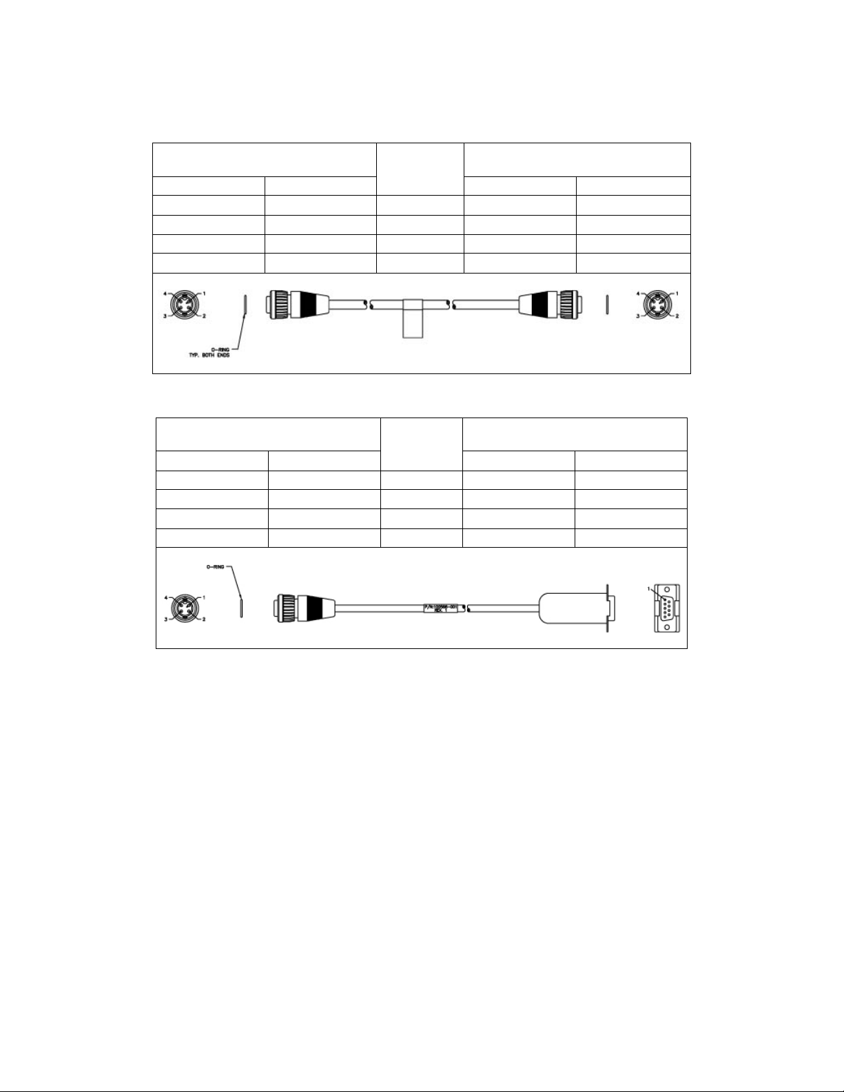
Appendix A - Interface Cable Pinouts
Table A.1 – DS-3 Data Cables
Link CX-24 IN/OUT TNC
Connectors
Pin Function
1 RX – TX 1
Shield GND Foil GND Shield
2 TX – RX 2
Shield GND Foil GND Shield
Table A.2 – 10/100 Ethernet Data or Control Cable
Link CX-24 ETHERNET
1/2 Connectors
Pin Function
1 RX+ White/Orange TX+ 1
2 RX- Orange TX- 2
3 TX+ White/Green RX+ 3
4 TX- Green RX- 6
Wire Color
Wire Color
DS-3 Equipment BNC Port
Function Pin
Ethernet Equipment RJ-45 Port
Function Pin
Table A.3 – DC Power Cable
To Link CX-24 POWER
(4-pin Circular)
Pin Function
1 -V in White/Orange -V out White
2 – – – –
3 – – – –
4 +V in Red +V out Red
Version 1.0 Page 47 February 2004
Wire Color
To DC Power Supply
Function Wire
Page 11
Link CX-24 User’s Manual
Table A.4 – 10/100 Ethernet Crossover Cable
Link CX-24 ETHERNET
1/2 Connectors
Wire Color
Pin Function
Link CX-24 ETHERNET
1/2 Connectors
Function Pin
1 RX+ White/Orange TX+ 3
2 RX- Orange TX- 4
3 TX+ White/Green RX+ 1
4 TX- Green RX- 2
Table A.5 – RS-232 CLI Craft PC Cable
To Link CX-24 TEST (4-pin
Circular)
Pin Function
Wire Color
To Craft PC Serial DB-9 Port
Function Pin
1 N/C – N/C –
2 RS-232 RX Red RS-232 TX 3
3 RS-232 TX Black RS-232 RX 2
4 RS-232 GND Yellow RS-232 GND 5
Version 1.0 Page 48 February 2004
Page 12

Link CX-24 User’s Manual
Appendix B - Technical Specifications
Table B.1 – Link CX-24 DS-3 or Ethernet Version (24 GHz)
General
Frequency Range 24.05-24.250 GHz
Compliance (USA) FCC Rules Part 15.249
Capacity
Emission Bandwidth 26 dB at 13.9 MHz
Channel Center Frequencies
• Channel 1 (Tx Low/Rx High) Transmit -- 24.072GHz/Receive -- 24.212GHz
• Channel 1 (Tx High/Rx Low) Transmit -- 24.212GHz/Receive -- 24.072GHz
• Channel 2 (Tx Low/Rx High) Transmit -- 24.088GHz/Receive -- 24.228GHz
• Channel 2 (Tx High/Rx Low) Transmit -- 24.228GHz/Receive -- 24.088GHz
Modulation Type 16 QAM
Transmitter
Maximum RMS Power Output 0 dBm
Power Output Stability +/- 2 dB
Frequency Stability +/- 0.24MHz
Transmit Duty Cycle 100%
Emissions Mask & Spurious and Harmonic Output Per FCC CFR 47 Part 15.249
Channel Frequency Selection Software-controlled
Automatic Tx Power Control (ATPC)
Transmitter Attenuation Range
Receiver
Type Double Heterodyne
Error Correction FEC Reed Solomon Decoding
Sensitivity at 10-6 BER -78 dBm state guaranteed
Typical Unfaded BER 10
Frequency Stability +/- 0.24MHz
Channel Frequency Selection Software-controlled
Maximum Receive Level without Receiver
Degradation
Maximum Receive Level without Receiver
Damage
Full-duplex DS-3, per Bellcore GR-499-CORE, or
45 Mbps Ethernet, per IEEE 802.3
Maintains a constant Carrier-to-Noise Ratio at both
ends of a link, operator enabled ON or OFF
0-30 dB in 1 dB steps, and Mute 40 dB, operator
controlled
-10
-35 dBm
-30 dBm
Version 1.0 Page 49 February 2004
Page 13

Link CX-24 User’s Manual
Table B.1 – Link CX-24 DS-3 or Ethernet Version (24GHz) (continued)
DS-3 Interface
Type Full-duplex DS-3, per Bellcore GR-499-CORE
Line Rate 44.736 Mbps
Line Code B3ZS
Tx and Rx Electrical Interfaces 75 Ohm unbalanced
Tx and Rx Physical Connectors Female TNC coaxial with grounded outer conductor
Ethernet Interfaces
Number
Two, with independent transmit and receive pair
sensing
Type Full-duplex 10/100 Base-T per IEEE 802.3
Line Rate 45 Mbps
Max Distance between CPE and Link CX-24 100 m (328 ft.)
Electrical Interfaces 100 Ohm UTP
Physical Connectors Female four-pin Circular
Other Interfaces
Craft Port
RSSI
Male four-pin Circular, RS-232 asynchronous data
port (TXD, RXD, GND)
Female BNC, DC voltage level proportionate to
Received Signal Strength
Power Requirements
DC Source +/- 21 to +/- 60 VDC
Power Consumption 36 watts typical
Undervoltage Protection Circuit > +/- 18 VDC to power up the Link CX-24
Physical Connector Male four-pin Circular
Environmental
Ambient Temperature Range
• Operational -32 to +60°C (-27 to +140°F)
• Storage -40 to +85°C (-40 to +185°F)
Relative Humidity
• Operational 100%, all weather protection
• Storage 95%, non-condensing
Altitude
• Operational 15,000 ft. AMSL (4,500m)
• Storage 50,000 ft. AMSL (15,000m)
Mechanical
Height (HxWxD) 30 x 30 x 10.6 cm (12 x 12 x 4.25 in.)
Weight (TBD) kg ( lb.); Shipping Weight: kg ( lb.)
Table B.2 describes the specifications for the integral antenna on the Link CX-24. Table B.3 gives the
Linx CX-24 availability figures for North America.
Version 1.0 Page 50 February 2004
Page 14

Link CX-24 User’s Manual
Table B.2 – Integral Reflector Antenna
Size
Mounting
Polarization
30 cm diameter x 1.9 cm deep
(12 in diameter x 0.75 in deep)
Permanently attached to the Link CX-24 radio;
gasketed to prevent moisture intrusion
Horizontal or vertical, depending on Link CX-24
mounting position
Forward Gain 34.5 dBi
Front/Back Ratio >45 dB
Beam Width 2.9°
Elevation Adjustment ± 15°
Azimuth Adjustment 360°
Table B.3 – Link CX-24 Availability – North America
Carrier
Grade
99.999%
0.4
Typical
Application
Avai lability
Rain Outage at Maximum
Distance (minutes/month)
Maximum Distance1
(miles)
ITU Rain Zone
A (Arctic)
B (Nevada, Idaho, Inland BC)
C (Anchorage)
D (San Francisco, Sacramento)
E (Los Angeles, San Diego)
F (Newfoundland)
K (New York, Philadelphia)
M (Dallas, Atlanta)
N (New Orleans, Miami)
Hotspot/ISP/WISP
WAN
99.7%
131
99.9%
44
99.97%
13
99.99%
4
VOIP
99.997%
1
5.5 5.0 4.1 3.5 2.8 2.2
5.0 4.6 3.9 3.0 2.3 1.8
4.2 4.1 3.4 2.7 2.0 1.5
4.3 3.5 2.9 2.4 1.9 1.5
4.9 3.9 3.0 2.2 1.5 1.1
4.3 3.5 2.7 1.9 1.3 0.9
4.3 3.0 2.1 1.5 1.1 0.8
3.1 2.2 1.5 1.1 0.8 0.7
2.7 1.7 1.1 0.8 0.6 0.5
1. Maximum Distance and Availability based on Line-of-Site installation and ITU average rainfall statistics. Actual performance
may vary.
Version 1.0 Page 51 February 2004
Page 15
Link CX-24 User’s Manual
Appendix C - Using the Web-Based GUI User Interface
30000
The Link CX-24 includes its own HTML-based installation, operation and test Web pages, which can be
accessed locally using a Web browser on a Craft PC, or remotely using any Web browser on the same
network as the Link CX-24.
C-1 Web Browser Requirements
The Web browser used to install, operate, and maintain the Link CX-24 must have an HTML-enabled
interface.
C-2 Connecting A Web Browser
You must connect your Web browser to the Link CX-24; either locally using a Craft PC, or remotely using
any Web browser on the same Ethernet network as the Link CX-24. The web browser platform must have
an Ethernet adapter for connecting to the Link CX-24 directly, or to the Link CX-24 though other Ethernet
equipment.
C-3 Accessing the Link CX-24 Web Pages
Once your Web browser is connected to the Link CX-24 as described in Section C-2, you can access and
move through the configuration and maintenance pages as you would any other Web site. The rest of this
paragraph will describe how to access the Link CX-24 Web pages.
C-4 Link CX-24 Web Pages
The following figures show the Link CX-24 Web pages, and Chapter Four through Chapter Seven
describe how to use the Link CX-24 Web pages to configure, install, and maintain the Link CX-24.
C-4.1 All Versions
To access the Link CX-24 built-in website, connect the Link CX-24 to your Craft PC using the Ethernet
cable, open your Craft PC web browser, and open Ethernet address http:// 10.0.0.2/ (transmit low
models) or http://10.0.0.3/ (transmit high models) in the web browser.
When the web browser Ethernet address has been changed, use the replacement Ethernet address
instead of http://10.0.0.x/
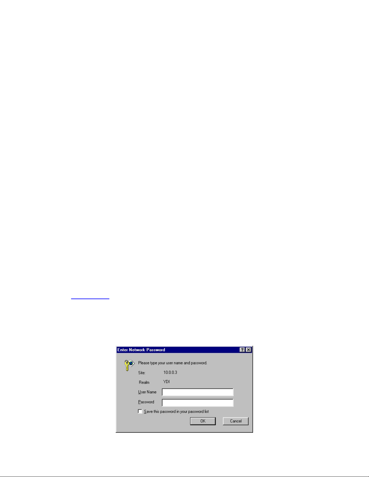
When the Link CX-24 is configured for a password, enter it in the window shown in Figure C.1, and the
web browser takes you to Figure C.2 (DS-3 models). When the Link CX-24 is not configured for a
password, the web browser takes you directly to Figure C.2.
.
Figure C.1 – Link CX-24 Login Window (all models)
Version 1.0 Page 52 February 2004
Page 16

Link CX-24 User’s Manual
C-4.2 DS-3 Versions
Figure C.2 – Link CX-24 DS-3 Monitor Web Page
Note that the Monitor page has a hypertext link to the Link CX-24 on the far end of the radio link for faster
troubleshooting and easy movement between the two Link CX-24s.
Figure C.3 – Link CX-24 DS-3 Commission Radio Web Page
Version 1.0 Page 53 February 2004
Page 17

Link CX-24 User’s Manual
Figure C.4 – Link CX-24 DS-3 Commission Manager Web Page
Version 1.0 Page 54 February 2004
Page 18

Link CX-24 User’s Manual
Figure C.5 – Link CX-24 DS-3 Test Web Page
Figure C.6 – Link CX-24 DS-3 Update Software Web Page
Version 1.0 Page 55 February 2004
Page 19

Link CX-24 User’s Manual
C-4.3 Ethernet Versions
Figure C.7 – Link CX-24 Ethernet Monitor Web Page
Note that the Monitor page has a hypertext link to the Link CX-24 on the far end of the radio link for faster
troubleshooting and easy movement between the two Link CX-24s.
Figure C.8 – Link CX-24 Ethernet Commission Radio Web Page
Version 1.0 Page 56 February 2004
Page 20

Link CX-24 User’s Manual
Figure C.9 – Link CX-24 Ethernet Commission Manager Web Page
Figure C.10 – Link CX-24 Ethernet Test Web Page
Figure C.11 – Link CX-24 Ethernet Update Software Web Page
Version 1.0 Page 57 February 2004
Page 21

Link CX-24 User’s Manual
Appendix D - Grounding and Lightning Protection
This appendix explains how to properly set up the Link CX-24 radio for grounding and lightning protection.
D-1 Overview
When used in telecommunications, good grounding practices have some direct benefits that can help
users maximize system uptime as well as ensure the safety of those people working on the system.
Among these benefits are:
• Protection of personnel from electric shock and fire hazards
• Reduction of radiated and conducted electromagnetic susceptibility
• Improved system tolerance to discharge of electrostatic energy and lightning interference
• Minimized service interruptions and service damage
No practice or formula can completely eliminate the above risks, but YDI believes that good grounding
and bonding practices can significantly reduce the risk of many of these hazards. This appendix includes
a bibliography that contains several publications that are readily available and provide detailed
information on many aspects of grounding systems and their design, implementation, measurement, and
maintenance.
Please note that every telecommunication site is unique and must be evaluated accordingly. The
following information is provided for generic reference and educational purposes only. The grounding
plans and practices for a given site should be established and implemented only by trained professionals,
working in accordance with local practices and regulations.
YDI strongly recommends that you install a Transtector Lightning Arrestor or equivalent at the cable entry
to the Ethernet, Power, and/or DS-3 equipment structure.
D-2 Grounding
D-2.1 Making a Grounding Plan
A grounding plan should be developed at the outset of site design to provide the best grounding
procedures and to minimize ground loop currents. Grounding should be achieved by connecting the outer
conductors of the cables through a large-section copper strap to a central grounding point, and the size of
the conductor should be increased as each branch path is added. The final conductor should be
connected directly to the grounding system. For a radio site, a single copper grounding rod is insufficient,
because its impedance is likely to be too high.
D-2.2 Grounding Buildings
Ideally, a ground ring should surround the building and be connected to individual grounds associated
with feeder entry, antenna support structure, the building lightning conductor, the equipment room, the
main AC supply, and other facilities. Each connection should be made by the most direct route to
minimize interaction between the different grounding functions.
The ground ring should consist of copper cable or tape with electrodes two meters or longer, buried to a
depth of 0.6 m and at a distance from the building not to exceed 1 m.
Buildings may require lightning rods if they are not within the zone of another protected structure. To
construct a good ground, ground rods should penetrate the earth to a depth of about 2 m (6 feet).
Where the ground is in rocky terrain, make sure that the ground rods penetrate into loose soil. In sandy
soil, use more ground rods to make sure that the ground has sufficient contact with water-bearing
material.
Version 1.0 Page 58 February 2004
Page 22

Link CX-24 User’s Manual
Use 4 to 6 AWG wire to connect each ground rod to the equipment to be grounded. The cables should be
free of sharp bends. Each ground cable should be at least 2 m in length with at least 1 m separation
between each. Refer to local and national electrical codes to determine acceptable grounding methods.
The Link CX-24 chassis should be directly connected to ground to ensure that it functions correctly. In
most cases, following the local code requirements for grounding and lightning protection will be adequate.
Many of the cables used by YDI have braided rather than solid outer conductors; this type of grounding is
not appropriate. In these cases surge arrestors approved by YDI should be used. For information on
surge arrestors, please contact the YDI Customer Support department.
D-3 Lightning Protection
Radio sites can be particularly prone to lightning strikes by virtue of their normally exposed locations and
the presence of relatively tall antenna support structures.
Reference should also be made to various publications, some of which are listed in the bibliography.
Any site owner or user in doubt about the protection requirements for a particular location should contact
the appropriate authority.
D-3.1 Purposes
The purposes of any protection arrangement should be to:
• Provide a suitable path to ground for the lightning current.
• Ensure adequate bonding between structures and all metalwork on the site and the common
grounding system in order to reduce side flashing.
• Prevent the entry of flashes or surges into the building.
The resistance to ground should be kept to a minimum; a value of less than 10 Ohms is recommended.
Ideally, and most important, the system should be at equal potential across the entire site.
Certain authorities and service providers have their own particular practices that have to be followed
where applicable.
Protection arrangements vary considerably, from very simple sites to complicated sites with multiple
buildings, antenna support structures, and associated equipment. Ensuring adequate protection may also
involve integration with and upgrading of existing systems.
D-3.2 Lightning Conductors
Down conductors, bonding interconnections, ground rings, and radial tapes should be of uninsulated 000
AWG copper cable or solid copper tape with a minimum cross section of 25 mm by 3 mm, with all
connections protected by non-reactive paste.
Protected test points should be included if appropriate, and sacrificial ground lugs should be clearly
marked and easily accessible for periodic inspection.
D-3.3 Grounding Antenna Support Structures
A structure generally acts as its own lightning conductor and, therefore, does not require an additional
conductor from the top to the base. A lightning rod may be required to extend the zone of protection to
equipment mounted on the top of the structure. The lightning rod should extend 2.5 m above the highest
equipment.
It is not possible to provide and guarantee complete protection from the effects of lightning; however,
risks of this sort can be significantly reduced by careful attention to grounding, protection devices, and the
layout of the site itself.
Version 1.0 Page 59 February 2004
Page 23

Link CX-24 User’s Manual
Ground-mounted support structures should be connected at their base to a ground ring through sacrificial
ground lugs. Towers should have a connection from each leg.
A ground ring should consist of copper cable or solid copper tape, with ground rods equally spaced at 2 m
intervals around the base of the structure as close to it as possible. The ground ring is buried
approximately 0.6 m deep where soil conditions allow. An alternative method using radials rather than
rings is detailed in The “Grounds” for Lightning and EMP Protection, published by PolyPhaser
Corporation.
The ground ring should be connected to the main building ground by the most direct route, and should be
buried as appropriate.
Roof-mounted structures should be connected to the main building ground by the most direct route, using
sacrificial lugs and copper cable or tape as appropriate. Tower guy wires should be directly bonded at
their lowest point to a suitable ground electrode or connected to the site ground by the most direct route.
Version 1.0 Page 60 February 2004
Page 24

Link CX-24 User’s Manual
Appendix E - Enterprise MIBs and Traps
This appendix contains information about the two different sets of Link CX-24 Management Information
Bases (MIBs), their current listings, and where to find the most current versions.
E-1 Enterprise MIBs
E-1.1 Overview
The DS-3 and Ethernet Link CX-24 Enterprise MIBs consist of the following groups of objects:
• link_cx_identity group: Model, revision, serial numbers, and channel frequency table.
Configured in the factory. Read-only by the customer.
• link_cx_configuration group: Channel number and other read-write parameters that the customer
chooses. This group is the system’s persistent state. It is preserved across reboots.
• link_cx_status group: Performance and alarm status, read-only. Not preserved across reboots.
• link_cx_test group: BERT, loopback, and other temporary state that the customer might use in a
test procedure. Read-write. Not preserved across reboots.
• link_cx_reboot group: Identifies the software versions that are available and controls reboot.
• link_cx_trap group: There is only one trap-related variable, trapSentCounter. It is not preserved
across reboots.
The following two sections contain details for the DS-3 and Ethernet Link CX-24 Enterprise MIBs.
E-1.2 DS-3 Version Details
LINK_CX-MIB DEFINITIONS ::= BEGIN
IMPORTS
enterprises, Counter
FROM RFC1155-SMI
OBJECT-TYPE
FROM RFC-1212;
YDI_Wireless OBJECT IDENTIFIER ::= { enterprises 792 }
link_cx OBJECT IDENTIFIER ::= {YDI_Wireless 5 }
link_cx_identity OBJECT IDENTIFIER ::= { link_cx 1 }
link_cx_configuration OBJECT IDENTIFIER ::= { link_cx 2 }
link_cx_status OBJECT IDENTIFIER ::= { link_cx 3 }
link_cx_test OBJECT IDENTIFIER ::= { link_cx 4 }
link_cx_reboot OBJECT IDENTIFIER ::= { link_cx 5 }
link_cx_trap OBJECT IDENTIFIER ::= { link_cx 6 }
-- link_cx_identity group
unitModelNumber OBJECT-TYPE
SYNTAX DisplayString (SIZE (0..15))
ACCESS read-only
STATUS mandatory
DESCRIPTION
"The model number of the unit as a whole."
::= { link_cx_identity 1 }
unitRevisionNumber OBJECT-TYPE
SYNTAX DisplayString (SIZE (0..15))
ACCESS read-only
STATUS mandatory
Version 1.0 Page 61 February 2004
Page 25

Link CX-24 User’s Manual
DESCRIPTION
"The revision number of the unit as a whole."
::= { link_cx_identity 2 }
unitSerialNumber OBJECT-TYPE
SYNTAX DisplayString (SIZE (0..15))
ACCESS read-only
STATUS mandatory
DESCRIPTION
"The serial number of the unit as a whole."
::= { link_cx_identity 3 }
boardModelNumber OBJECT-TYPE
SYNTAX DisplayString (SIZE (0..15))
ACCESS read-only
STATUS mandatory
DESCRIPTION
"The model number of the PCB board assembly."
::= { link_cx_identity 4 }
boardRevisionNumber OBJECT-TYPE
SYNTAX DisplayString (SIZE (0..15))
ACCESS read-only
STATUS mandatory
DESCRIPTION
"The revision number of the PCB board assembly."
::= { link_cx_identity 5 }
boardSerialNumber OBJECT-TYPE
SYNTAX DisplayString (SIZE (0..15))
ACCESS read-only
STATUS mandatory
DESCRIPTION
"The serial number of the PCB board assembly."
::= { link_cx_identity 6 }
rfFrequencyTable OBJECT-TYPE
SYNTAX SEQUENCE OF RfChannelFreqEntry
ACCESS not-accessible
STATUS mandatory
DESCRIPTION
"The table of 2 selectable Tx/Rx frequency channel pairs, in MHz. The
receive frequency on a Tx-high unit is lower than the transmit frequency
by the amount of the Tx/Rx separation. Conversely, the receive frequency
on a Tx-low unit is higher than the transmit frequency by the amount of
the Tx/Rx separation."
::= { link_cx_identity 7 }
rfFrequencyEntry OBJECT-TYPE
SYNTAX RfFrequencyEntry
ACCESS not-accessible
STATUS mandatory
DESCRIPTION
"Channel frequency entry."
INDEX { rfChannelIndex }
::= { rfFrequencyTable 1 }
Version 1.0 Page 62 February 2004
Page 26

Link CX-24 User’s Manual
RfFrequencyEntry ::=
SEQUENCE {
rfChannelIndex
INTEGER,
rfTxFrequency
INTEGER,
rfRxFrequency
INTEGER
}
rfChannelIndex OBJECT-TYPE
SYNTAX INTEGER (1..2)
ACCESS read-only
STATUS mandatory
DESCRIPTION
"The RF channel number."
::= { rfFrequencyEntry 1 }
rfTxFrequency OBJECT-TYPE
SYNTAX INTEGER
ACCESS read-only
STATUS mandatory
DESCRIPTION
"The transmit frequency in MHz."
::= { rfFrequencyEntry 2 }
rfRxFrequency OBJECT-TYPE
SYNTAX INTEGER
ACCESS read-only
STATUS mandatory
DESCRIPTION
"The receive frequency in MHz."
::= { rfFrequencyEntry 3 }
-- link_cx_configuration group
rfTxAttenuateControl OBJECT-TYPE
SYNTAX INTEGER {
enabled(1),
disabled(2)
}
ACCESS read-write
STATUS mandatory
DESCRIPTION
"If enabled, attenuates the transmit output level by 40 dB."
::= { link_cx_configuration 1 }
rfAtpcControl OBJECT-TYPE
SYNTAX INTEGER {
enabled(1),
disabled(2)
}
ACCESS read-write
STATUS mandatory
DESCRIPTION
Version 1.0 Page 63 February 2004
Page 27

Link CX-24 User’s Manual
"Automatic Tx Power Control mode can be enabled or disabled.
If enabled, the two Link CX-24 radios at opposite ends of the
radio link send each other feedback messages that they use
to adjust their Tx power down to the lowest level that is
consistent with good signal quality."
::= { link_cx_configuration 2 }
rfTxPowerLimit OBJECT-TYPE
SYNTAX INTEGER (-30..0)
ACCESS read-write
STATUS mandatory
DESCRIPTION
"Maximum transmit power level limit at the antenna port, in dBm.
The Tx power limit can be set in 1 dB steps within the range
of -30 dBm to 0 dBm. If Automatic Tx Power Control is enabled
the measured Tx power may be lower than this limit. If Automatic
Tx Power Control is disabled the measured Tx power should be
exactly the same as this target value."
::= { link_cx_configuration 3 }
rfAtpcAddress OBJECT-TYPE
SYNTAX IpAddress
ACCESS read-write
STATUS mandatory
DESCRIPTION
"The IP Address of the peer radio with which this radio exchanges
Automatic Tx Power Control information."
::= { link_cx_configuration 4 }
rfChannel OBJECT-TYPE
SYNTAX INTEGER (1..2)
ACCESS read-write
STATUS mandatory
DESCRIPTION
"The current transmit channel of the local unit. The transmit
frequency in MHz for each channel can be read in the rfFrequencyTable."
::= { link_cx_configuration 5 }
rfRssiAlarmThresholdSetting OBJECT-TYPE
SYNTAX INTEGER (-80..-40)
ACCESS read-write
STATUS mandatory
DESCRIPTION
"A RSSI Alarm will be generated if the level of RSSI goes below
the set threshold. The threshold can be set in 1 dB steps
within the range of -80 to -40 dBm."
::= { link_cx_configuration 6 }
losAlarmControl OBJECT-TYPE
SYNTAX INTEGER {
enabled(1),
disabled(2)
}
ACCESS read-write
STATUS mandatory
DESCRIPTION
Version 1.0 Page 64 February 2004
Page 28

Link CX-24 User’s Manual
"DS3/E3 LOS alarm control. When enabled, the alarm will be generated.
When disabled, the alarm will not be generated even if
LOS condition is detected."
::= { link_cx_configuration 7 }
-- link_cx_status group
rfPowerOutputLevel OBJECT-TYPE
SYNTAX INTEGER
ACCESS read-only
STATUS mandatory
DESCRIPTION
"The measured radio Tx power level in dBm."
::= { link_cx_status 1 }
rfRssiLevel OBJECT-TYPE
SYNTAX INTEGER
ACCESS read-only
STATUS mandatory
DESCRIPTION
"The measured RSSI of the active channel in dBm. -110 dBm
indicates the receive signal level is below the detection level."
::= { link_cx_status 2 }
bitErrorRate OBJECT-TYPE
SYNTAX INTEGER
ACCESS read-only
STATUS mandatory
DESCRIPTION
"The estimated bit error rate (BER), in errors per 10^8 bits.
A returned value of 0 indicates zero bit errors in 10^8 bits.
A returned value of 1 indicates an estimated BER of 1x10^-8.
A returned value of 10 indicates an estimated BER of 1x10^-7,
and so on."
::= { link_cx_status 3 }
losAlarmStatus OBJECT-TYPE -- DS3/E3 interface alarm condition
SYNTAX INTEGER {
normal(1),
alarm(2)
}
ACCESS read-only
STATUS mandatory
DESCRIPTION
"A value of 1 indicates a DS3/E3 connection is present.
A value of 2 indicates the DS3/E3 connection has been lost.
If losAlarmControl = disabled, losAlarmStatus will
always be normal."
::= { link_cx_status 4 }
txSynthLockAlarmStatus OBJECT-TYPE -- local alarm condition
SYNTAX INTEGER {
normal(1),
alarm(2)
}
ACCESS read-only
Version 1.0 Page 65 February 2004
Page 29

Link CX-24 User’s Manual
STATUS mandatory
DESCRIPTION
"The Tx synthesizer lock status.
A value of 1 indicates the Tx synthesizer is locked.
A value of 2 indicates the Tx synthesizer is unlocked"
::= { link_cx_status 5 }
rxSynthLockAlarmStatus OBJECT-TYPE -- local alarm condition
SYNTAX INTEGER {
normal(1),
alarm(2)
}
ACCESS read-only
STATUS mandatory
DESCRIPTION
"The Rx synthesizer lock status.
A value of 1 indicates the Rx synthesizer is locked.
A value of 2 indicates the Rx synthesizer is unlocked"
::= { link_cx_status 6 }
lowTxPowerAlarmStatus OBJECT-TYPE -- local alarm condition
SYNTAX INTEGER {
normal(1),
alarm(2)
}
ACCESS read-only
STATUS mandatory
DESCRIPTION
"A value of 1 indicates the Tx power at the antenna port
is greater than or equal to -30dBm. A value of 2 indicates
the Tx power at the antenna port is less than -30 dBm."
::= { link_cx_status 7 }
demodLockAlarmStatus OBJECT-TYPE -- link alarm condition
SYNTAX INTEGER {
normal(1),
alarm(2)
}
ACCESS read-only
STATUS mandatory
DESCRIPTION
"The demodulator lock status.
A value of 1 indicates the demodulator is locked.
A value of 2 indicates the demodulator is unlocked"
::= { link_cx_status 8 }
lowRssiLevelAlarmStatus OBJECT-TYPE -- link alarm condition
SYNTAX INTEGER {
normal(1),
alarm(2)
}
ACCESS read-only
STATUS mandatory
DESCRIPTION
"A RSSI alarm will be generated if the level of RSSI goes below
the user configured RSSI alarm level, rfRssiAlarmThresholdSetting.
Version 1.0 Page 66 February 2004
Page 30

Link CX-24 User’s Manual
A value of 1 indicates the received signal level is above the RSSI
alarm threshold. A value of 2 indicates the received signal level
is at or below the user configured RSSI alarm level.
This alarm is valid only if the Rx synthesizer is locked."
::= { link_cx_status 9 }
receiverOverloadAlarmStatus OBJECT-TYPE -- link alarm condition
SYNTAX INTEGER {
normal(1),
alarm(2)
}
ACCESS read-only
STATUS mandatory
DESCRIPTION
"A receiver overload alarm will be generated if the level
of RSSI is at or above -40 dBm. A value of 1 indicates the
received signal level is below -40 dBm. A value of 2 indicates
the received signal level is at or above -40 dBm.
This alarm is only valid if the Rx synthesizer is locked."
::= { link_cx_status 10 }
bitErrorRateAlarmStatus OBJECT-TYPE -- link alarm condition
SYNTAX INTEGER {
normal(1),
alarm(2)
}
ACCESS read-only
STATUS mandatory
DESCRIPTION
"A bit error rate alarm will be generated if the level
of BER is at or above 10^-3, i.e. if bitErrorRate is
equal to or greater than 100000."
::= { link_cx_status 11 }
-- link_cx_test group
rfTxAttenuateTimer OBJECT-TYPE
SYNTAX INTEGER (0..1800)
ACCESS read-write
STATUS mandatory
DESCRIPTION
"To temporarily enable Tx attenuation by 40 dB, write the number of
seconds to this timer. When the timer counts down to 0, Tx attenuation
will return to its normal unattenuated state. Writing to this timer
has no effect if rfTxAttenuateControl is set to enable because in
that case the transmitter is already attenuated."
::= { link_cx_test 1 }
localLoopbackControl OBJECT-TYPE
SYNTAX INTEGER {
enabled(1),
disabled(2)
}
ACCESS read-write
STATUS mandatory
DESCRIPTION
Version 1.0 Page 67 February 2004
Page 31

Link CX-24 User’s Manual
"The DS3/E3 local loopback control. When enabled, DS3/E3 data on the
local interface is looped back through the local interface.
When disabled, DS3/E3 data on the local interface is sent over
the radio link to the remote unit."
::= { link_cx_test 2 }
rfLocalLoopbackTimer OBJECT-TYPE
SYNTAX INTEGER (0..1800)
ACCESS read-write
STATUS mandatory
DESCRIPTION
"When this value is greater than zero, the radio is in the local
loopback mode. The RF transmit signal on the local unit is
converted to the receive frequency of the local unit so it can
be received by the local unit, for the chosen period of time in
seconds. When this timer counts down to 0 the unit reverts to
normal operation in which the RF transmit signal on the local unit
is transmitted over the radio link to the remote unit. The duration
is selectable in 1 second intervals from 0 seconds to a maximum of
1800 seconds."
::= { link_cx_test 3 }
remoteLoopbackControl OBJECT-TYPE
SYNTAX INTEGER {
enabled(1),
disabled(2)
}
ACCESS read-write
STATUS mandatory
DESCRIPTION
"The DS3/E3 remote loopback control. With either setting of this
control, DS3/E3 data on the local interface is sent to the peer radio
and DS3/E3 data received from the peer radio goes to the local
interface. When enabled, the peer radio loops the data back to the
originating radio. When disabled, DS3/E3 data flow from end to end."
::= { link_cx_test 4 }
berTestControl OBJECT-TYPE
SYNTAX INTEGER {
alternatingOnesZeros(1),
allOnes(2),
allZeros(3),
disabled(4),
pseudorandom(5)
}
ACCESS read-write
STATUS mandatory
DESCRIPTION
"BER test mode control. The BER test is enabled by selecting one of
four different data patterns. The patterns are:
(1) alternating 1's and 0's, (2) all 1's, (3) all 0's, and
(5) pseudorandom 1's and 0's. The BER test is disabled by setting
the BER test control to 4."
::= { link_cx_test 5 }
pseudoAisControl OBJECT-TYPE
Version 1.0 Page 68 February 2004
Page 32

Link CX-24 User’s Manual
SYNTAX INTEGER {
enabled(1),
disabled(2)
}
ACCESS read-write
STATUS mandatory
DESCRIPTION
"When enabled, pseudo-AIS (constant mark or all ones at the DS3/E3
interface) will be generated."
::= { link_cx_test 6 }
-- link_cx_reboot group
softwareVersionBank1 OBJECT-TYPE
SYNTAX DisplayString (SIZE (0..15))
ACCESS read-only
STATUS mandatory
DESCRIPTION
"The software version in bank one."
::= { link_cx_reboot 1 }
softwareVersionBank2 OBJECT-TYPE
SYNTAX DisplayString (SIZE (0..15))
ACCESS read-only
STATUS mandatory
DESCRIPTION
"The software version in bank two."
::= { link_cx_reboot 2 }
bootedUsingBankNumber OBJECT-TYPE
SYNTAX INTEGER {
bankOne(1),
bankTwo(2)
}
ACCESS read-only
STATUS mandatory
DESCRIPTION
"The software bank from which the unit booted."
::= { link_cx_reboot 3 }
bootUsingBankNumber OBJECT-TYPE
SYNTAX INTEGER {
bankOne(1),
bankTwo(2)
}
ACCESS read-write
STATUS mandatory
DESCRIPTION
"Selects the software bank and causes reboot."
::= { link_cx_reboot 4 }
-- traps
trapSentCounter OBJECT-TYPE
SYNTAX Counter
ACCESS read-only
Version 1.0 Page 69 February 2004
Page 33

Link CX-24 User’s Manual
STATUS mandatory
DESCRIPTION
"Total number of enterprise traps sent since last reboot."
::= { link_cx_trap 1 }
link_cx_unit OBJECT IDENTIFIER ::= { link_cx 101 }
alarmTrap TRAP-TYPE
ENTERPRISE link_cx_unit
VARIABLES { rfPowerOutputLevel,
rfRssiLevel,
bitErrorRate,
losAlarmStatus,
txSynthLockAlarmStatus,
rxSynthLockAlarmStatus,
lowTxPowerAlarmStatus,
demodLockAlarmStatus,
lowRssiLevelAlarmStatus,
receiverOverloadAlarmStatus,
bitErrorRateAlarmStatus,
trapSentCounter }
DESCRIPTION
"A trap that indicates a change in one or more of the alarm conditions."
::= 1
configurationChangeTrap TRAP-TYPE
ENTERPRISE link_cx_unit
VARIABLES { rfTxAttenuateControl,
rfAtpcControl,
rfTxPowerLimit,
rfAtpcAddress,
rfChannel,
rfRssiAlarmThresholdSetting,
losAlarmControl,
trapSentCounter }
DESCRIPTION
"A trap that indicates a configuration change."
::= 2
unitTestTrap TRAP-TYPE
ENTERPRISE link_cx_unit
VARIABLES { rfTxAttenuateTimer,
localLoopbackControl,
rfLocalLoopbackTimer,
remoteLoopbackControl,
berTestControl,
pseudoAisControl,
trapSentCounter }
DESCRIPTION
"A trap that indicates the beginning or end of a test procedure.
An alarmTrap trap might result from this procedure."
::= 3
END
Version 1.0 Page 70 February 2004
Page 34

Link CX-24 User’s Manual
E-1.3 Ethernet Version Details
LINK_CX_ETHR_MIB DEFINITIONS ::= BEGIN
IMPORTS
enterprises, Counter
FROM RFC1155-SMI
OBJECT-TYPE
FROM RFC-1212;
YDI_Wireless OBJECT IDENTIFIER ::= { enterprises 792 }
link_cx_ethr OBJECT IDENTIFIER ::= {YDI_Wireless 6 }
link_cx_identity OBJECT IDENTIFIER ::= { link_cx_ethr 1 }
link_cx_configuration OBJECT IDENTIFIER ::= { link_cx_ethr 2 }
link_cx_status OBJECT IDENTIFIER ::= { link_cx_ethr 3 }
link_cx_test OBJECT IDENTIFIER ::= { link_cx_ethr 4 }
link_cx_reboot OBJECT IDENTIFIER ::= { link_cx_ethr 5 }
link_cx_trap OBJECT IDENTIFIER ::= { link_cx_ethr 6 }
-- link_cx_identity group
unitModelNumber OBJECT-TYPE
SYNTAX DisplayString (SIZE (0..15))
ACCESS read-only
STATUS mandatory
DESCRIPTION
"The model number of the unit as a whole."
::= { link_cx_identity 1 }
unitRevisionNumber OBJECT-TYPE
SYNTAX DisplayString (SIZE (0..15))
ACCESS read-only
STATUS mandatory
DESCRIPTION
"The revision number of the unit as a whole."
::= { link_cx_identity 2 }
unitSerialNumber OBJECT-TYPE
SYNTAX DisplayString (SIZE (0..15))
ACCESS read-only
STATUS mandatory
DESCRIPTION
"The serial number of the unit as a whole."
::= { link_cx_identity 3 }
boardModelNumber OBJECT-TYPE
SYNTAX DisplayString (SIZE (0..15))
ACCESS read-only
STATUS mandatory
DESCRIPTION
"The model number of the PCB board assembly."
::= { link_cx_identity 4 }
boardRevisionNumber OBJECT-TYPE
SYNTAX DisplayString (SIZE (0..15))
ACCESS read-only
Version 1.0 Page 71 February 2004
Page 35

Link CX-24 User’s Manual
STATUS mandatory
DESCRIPTION
"The revision number of the PCB board assembly."
::= { link_cx_identity 5 }
boardSerialNumber OBJECT-TYPE
SYNTAX DisplayString (SIZE (0..15))
ACCESS read-only
STATUS mandatory
DESCRIPTION
"The serial number of the PCB board assembly."
::= { link_cx_identity 6 }
rfFrequencyTable OBJECT-TYPE
SYNTAX SEQUENCE OF RfChannelFreqEntry
ACCESS not-accessible
STATUS mandatory
DESCRIPTION
"The table of 2 selectable Tx/Rx frequency channel pairs, in MHz. The
receive frequency on a Tx-high unit is lower than the transmit frequency
by the amount of the Tx/Rx separation. Conversely, the receive frequency
on a Tx-low unit is higher than the transmit frequency by the amount of
the Tx/Rx separation."
::= { link_cx_identity 7 }
rfFrequencyEntry OBJECT-TYPE
SYNTAX RfFrequencyEntry
ACCESS not-accessible
STATUS mandatory
DESCRIPTION
"Channel frequency entry."
INDEX { rfChannelIndex }
::= { rfFrequencyTable 1 }
RfFrequencyEntry ::=
SEQUENCE {
rfChannelIndex
INTEGER,
rfTxFrequency
INTEGER,
rfRxFrequency
INTEGER
}
rfChannelIndex OBJECT-TYPE
SYNTAX INTEGER (1..2)
ACCESS read-only
STATUS mandatory
DESCRIPTION
"The RF channel number."
::= { rfFrequencyEntry 1 }
rfTxFrequency OBJECT-TYPE
SYNTAX INTEGER
ACCESS read-only
STATUS mandatory
Version 1.0 Page 72 February 2004
Page 36

Link CX-24 User’s Manual
DESCRIPTION
"The transmit frequency in MHz."
::= { rfFrequencyEntry 2 }
rfRxFrequency OBJECT-TYPE
SYNTAX INTEGER
ACCESS read-only
STATUS mandatory
DESCRIPTION
"The receive frequency in MHz."
::= { rfFrequencyEntry 3 }
-- link_cx_configuration group
rfTxAttenuateControl OBJECT-TYPE
SYNTAX INTEGER {
enabled(1),
disabled(2)
}
ACCESS read-write
STATUS mandatory
DESCRIPTION
"If enabled, attenuates the transmit output level by 40 dB."
::= { link_cx_configuration 1 }
rfAtpcControl OBJECT-TYPE
SYNTAX INTEGER {
enabled(1),
disabled(2)
}
ACCESS read-write
STATUS mandatory
DESCRIPTION
"Automatic Tx Power Control mode can be enabled or disabled.
If enabled, the two Link CX-24 radios at opposite ends of the
radio link send each other feedback messages that they use
to adjust their Tx power down to the lowest level that is
consistent with good signal quality."
::= { link_cx_configuration 2 }
rfTxPowerLimit OBJECT-TYPE
SYNTAX INTEGER (-30..0)
ACCESS read-write
STATUS mandatory
DESCRIPTION
"Maximum transmit power level limit at the antenna port, in dBm.
The Tx power limit can be set in 1 dB steps within the range
of -30 dBm to 0 dBm. If Automatic Tx Power Control is enabled
the measured Tx power may be lower than this limit. If Automatic
Tx Power Control is disabled the measured Tx power should be
exactly the same as this target value."
::= { link_cx_configuration 3 }
rfAtpcAddress OBJECT-TYPE
SYNTAX IpAddress
ACCESS read-write
Version 1.0 Page 73 February 2004
Page 37

Link CX-24 User’s Manual
STATUS mandatory
DESCRIPTION
"The IP Address of the peer radio with which this radio exchanges
Automatic Tx Power Control information."
::= { link_cx_configuration 4 }
rfChannel OBJECT-TYPE
SYNTAX INTEGER (1..2)
ACCESS read-write
STATUS mandatory
DESCRIPTION
"The current transmit channel of the local unit. The transmit
frequency in MHz for each channel can be read in the rfFrequencyTable."
::= { link_cx_configuration 5 }
rfRssiAlarmThresholdSetting OBJECT-TYPE
SYNTAX INTEGER (-80..-40)
ACCESS read-write
STATUS mandatory
DESCRIPTION
"A RSSI Alarm will be generated if the level of RSSI goes below
the set threshold. The threshold can be set in 1 dB steps
within the range of -80 to -40 dBm."
::= { link_cx_configuration 6 }
losAlarmControl OBJECT-TYPE
SYNTAX INTEGER {
enabled(1),
disabled(2)
}
ACCESS read-write
STATUS mandatory
DESCRIPTION
"Ethernet Loss Of Signal alarm control. When enabled, the alarm will
be generated. When disabled, the alarm will not be generated even if
LOS condition is detected."
::= { link_cx_configuration 7 }
-- link_cx_status group
rfPowerOutputLevel OBJECT-TYPE
SYNTAX INTEGER
ACCESS read-only
STATUS mandatory
DESCRIPTION
"The measured radio Tx power level in dBm."
::= { link_cx_status 1 }
rfRssiLevel OBJECT-TYPE
SYNTAX INTEGER
ACCESS read-only
STATUS mandatory
DESCRIPTION
"The measured RSSI of the active channel in dBm. -110 dBm
indicates the receive signal level is below the detection level."
::= { link_cx_status 2 }
Version 1.0 Page 74 February 2004
Page 38

Link CX-24 User’s Manual
bitErrorRate OBJECT-TYPE
SYNTAX INTEGER
ACCESS read-only
STATUS mandatory
DESCRIPTION
"The estimated bit error rate (BER), in errors per 10^8 bits.
A returned value of 0 indicates zero bit errors in 10^8 bits.
A returned value of 1 indicates an estimated BER of 1x10^-8.
A returned value of 10 indicates an estimated BER of 1x10^-7,
and so on."
::= { link_cx_status 3 }
losAlarmStatus OBJECT-TYPE -- interface alarm condition
SYNTAX INTEGER {
normal(1),
alarm(2)
}
ACCESS read-only
STATUS mandatory
DESCRIPTION
"A value of 1 indicates an Ethernet connection is present.
A value of 2 indicates the Ethernet connection has been lost.
If losAlarmControl = disabled, losAlarmStatus will
always be normal."
::= { link_cx_status 4 }
txSynthLockAlarmStatus OBJECT-TYPE -- local alarm condition
SYNTAX INTEGER {
normal(1),
alarm(2)
}
ACCESS read-only
STATUS mandatory
DESCRIPTION
"The Tx synthesizer lock status.
A value of 1 indicates the Tx synthesizer is locked.
A value of 2 indicates the Tx synthesizer is unlocked"
::= { link_cx_status 5 }
rxSynthLockAlarmStatus OBJECT-TYPE -- local alarm condition
SYNTAX INTEGER {
normal(1),
alarm(2)
}
ACCESS read-only
STATUS mandatory
DESCRIPTION
"The Rx synthesizer lock status.
A value of 1 indicates the Rx synthesizer is locked.
A value of 2 indicates the Rx synthesizer is unlocked"
::= { link_cx_status 6 }
lowTxPowerAlarmStatus OBJECT-TYPE -- local alarm condition
SYNTAX INTEGER {
normal(1),
Version 1.0 Page 75 February 2004
Page 39

Link CX-24 User’s Manual
alarm(2)
}
ACCESS read-only
STATUS mandatory
DESCRIPTION
"A value of 1 indicates the Tx power at the antenna port
is greater than or equal to -30 dBm. A value of 2 indicates
the Tx power at the antenna port is less than -30 dBm."
::= { link_cx_status 7 }
demodLockAlarmStatus OBJECT-TYPE -- link alarm condition
SYNTAX INTEGER {
normal(1),
alarm(2)
}
ACCESS read-only
STATUS mandatory
DESCRIPTION
"The demodulator lock status.
A value of 1 indicates the demodulator is locked.
A value of 2 indicates the demodulator is unlocked"
::= { link_cx_status 8 }
lowRssiLevelAlarmStatus OBJECT-TYPE -- link alarm condition
SYNTAX INTEGER {
normal(1),
alarm(2)
}
ACCESS read-only
STATUS mandatory
DESCRIPTION
"A RSSI alarm will be generated if the level of RSSI goes below
the user configured RSSI alarm level, rfRssiAlarmThresholdSetting.
A value of 1 indicates the received signal level is above the RSSI
alarm threshold. A value of 2 indicates the received signal level
is at or below the user configured RSSI alarm level.
This alarm is valid only if the Rx synthesizer is locked."
::= { link_cx_status 9 }
receiverOverloadAlarmStatus OBJECT-TYPE -- link alarm condition
SYNTAX INTEGER {
normal(1),
alarm(2)
}
ACCESS read-only
STATUS mandatory
DESCRIPTION
"A receiver overload alarm will be generated if the level
of RSSI is at or above -40 dBm. A value of 1 indicates the
received signal level is below -40 dBm. A value of 2 indicates
the received signal level is at or above -40 dBm.
This alarm is only valid if the Rx synthesizer is locked."
::= { link_cx_status 10 }
bitErrorRateAlarmStatus OBJECT-TYPE -- link alarm condition
SYNTAX INTEGER {
Version 1.0 Page 76 February 2004
Page 40

Link CX-24 User’s Manual
normal(1),
alarm(2)
}
ACCESS read-only
STATUS mandatory
DESCRIPTION
"A bit error rate alarm will be generated if the level
of BER is at or above 10^-3, i.e. if bitErrorRate is
equal to or greater than 100000."
::= { link_cx_status 11 }
-- link_cx_test group
rfTxAttenuateTimer OBJECT-TYPE
SYNTAX INTEGER (0..1800)
ACCESS read-write
STATUS mandatory
DESCRIPTION
"To temporarily enable Tx attenuation by 40 dB, write the number of
seconds to this timer. When the timer counts down to 0, Tx attenuation
will return to its normal unattenuated state. Writing to this timer
has no effect if rfTxAttenuateControl is set to enable because in
that case the transmitter is already attenuated."
::= { link_cx_test 1 }
-- link_cx_reboot group
softwareVersionBank1 OBJECT-TYPE
SYNTAX DisplayString (SIZE (0..15))
ACCESS read-only
STATUS mandatory
DESCRIPTION
"The software version in bank one."
::= { link_cx_reboot 1 }
softwareVersionBank2 OBJECT-TYPE
SYNTAX DisplayString (SIZE (0..15))
ACCESS read-only
STATUS mandatory
DESCRIPTION
"The software version in bank two."
::= { link_cx_reboot 2 }
bootedUsingBankNumber OBJECT-TYPE
SYNTAX INTEGER {
bankOne(1),
bankTwo(2)
}
ACCESS read-only
STATUS mandatory
DESCRIPTION
"The software bank from which the unit booted."
::= { link_cx_reboot 3 }
bootUsingBankNumber OBJECT-TYPE
SYNTAX INTEGER {
Version 1.0 Page 77 February 2004
Page 41

Link CX-24 User’s Manual
bankOne(1),
bankTwo(2)
}
ACCESS read-write
STATUS mandatory
DESCRIPTION
"Selects the software bank and causes reboot."
::= { link_cx_reboot 4 }
-- traps
trapSentCounter OBJECT-TYPE
SYNTAX Counter
ACCESS read-only
STATUS mandatory
DESCRIPTION
"Total number of enterprise traps sent since last reboot."
::= { link_cx_trap 1 }
link_cx_unit OBJECT IDENTIFIER ::= { link_cx_ethr 101 }
alarmTrap TRAP-TYPE
ENTERPRISE link_cx_unit
VARIABLES { rfPowerOutputLevel,
rfRssiLevel,
bitErrorRate,
losAlarmStatus,
txSynthLockAlarmStatus,
rxSynthLockAlarmStatus,
lowTxPowerAlarmStatus,
demodLockAlarmStatus,
lowRssiLevelAlarmStatus,
receiverOverloadAlarmStatus,
bitErrorRateAlarmStatus,
trapSentCounter }
DESCRIPTION
"A trap that indicates a change in one or more of the alarm conditions."
::= 1
configurationChangeTrap TRAP-TYPE
ENTERPRISE link_cx_unit
VARIABLES { rfTxAttenuateControl,
rfAtpcControl,
rfTxPowerLimit,
rfAtpcAddress,
rfChannel,
rfRssiAlarmThresholdSetting,
losAlarmControl,
trapSentCounter }
DESCRIPTION
"A trap that indicates a configuration change."
::= 2
unitTestTrap TRAP-TYPE
ENTERPRISE link_cx_unit
VARIABLES { rfTxAttenuateTimer,
Version 1.0 Page 78 February 2004
Page 42

Link CX-24 User’s Manual
trapSentCounter }
DESCRIPTION
"A trap that indicates the beginning or end of a test procedure.
An alarmTrap trap might result from this procedure."
::= 3
END
E-2 Enterprise Traps
Link CX-24 supports three enterpriseSpecific traps - alarmTrap, configurationChangeTrap, and unitTestTrap. Each of these traps contains all the relevant variables for that particular trap, in order to minimize
polling. One variable that is in each of the traps is a counter, so that the network management application
can detect loss of traps.
E-2.1 alarmTrap
Link CX-24 sends this trap when any of the alarm variables changes, either going into or out of an alarm
condition. All of the relevant alarm conditions and performance data are contained in the trap PDU, along
with a counter of enterprise traps sent. The variables include:
• trap counter
• DS3 LOS status (DS3 input absent/present)
• Tx Power status (under/over minimum power)
• Tx Synthesizer lock status (unlocked/locked)
• Rx Synthesizer lock status (unlocked/locked)
• RSSI level status (under minimum level)
• Rx overload status (over maximum level)
• BER status (over threshold)
• demodulator lock status (unlocked/locked)
• BER
• RSSI
• Tx Power
E-2.2 configurationChangeTrap
Link CX-24 sends this trap when the persistent state of the Link CX-24 changes. This trap alerts the
network management application that it must refresh its database. If all management is through SNMP
exclusively, this trap is redundant. If on the other hand, management is a mixture of HTTP and SNMP this
will keep the SNMP side completely consistent. All the relevant persistent state variables are contained in
the trap PDU, along with the trap counter. The variables include:
• trap counter
• Tx control (attenuated/unattenuated)
• ATPC control (ATPC enabled/disabled)
• Tx power setting
• ATPC peer IP address (IP address of the CX at the other end of the radio link)
• channel number
• RSSI alarm threshold
• DS3 LOS control (enable/disable alarm for LOS)
Version 1.0 Page 79 February 2004
Page 43

Link CX-24 User’s Manual
E-2.3 unitTestTrap
Link CX-24 sends this trap when any of the test variables change, either at the start or at completion of a
test. All the test state variables are contained in the trap PDU, along with the trap counter. This trap alerts
the management application that a change has taken place that will probably result in an alarmTrap
before too long (in case it doesn’t already know, and in case it wants to distinguish between this case and
spontaneous alarmTraps). The state variables in the trap PDU include:
• trap counter
• DS3 local loopback
• DS3 remote loopback
• radio loopback
• pseudoAIS
• BERT
• temporary Tx attenuation
Bibliography
ITU - T K.40 Protection against LEMP(Lightning ElectroMagnetic
Pulse) in telecommunications centers
ITU - T K.27 Bonding configurations and earthing inside a
telecommunication building
ITU - T K.35 Bonding configurations and earthing at remote electronic
sites
ITU - T K.39 Risk assessment of damages to telecommunications
sites due to lightning discharges
ITU - T Lightning Handbook The protection of telecommunication lines and
equipment against lightning discharges
IEEE Emerald Book Powering and Grounding
The “Grounds” for Lightning and EMP (Electromagnetic Pulse) Protection, second edition
Published by PolyPhaser Corporation
Version 1.0 Page 80 February 2004
Page 44

 Loading...