

YDI Wireless 2458-AL Users Manual

TABLE OF CONTENTS
1.0 DESCRIPTION ..................................................................................................................................................1
2.0 CONVERTER (ODU) FEATURES.................................................................................................................. 2
3.0 OUTDOOR UNIT SPECIFICATIONS............................................................................................................4
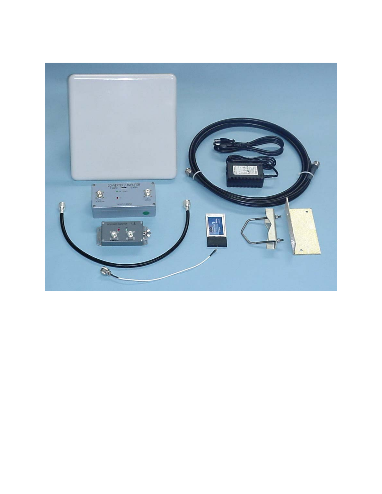
4.0 CONVERTER KIT ............................................................................................................................................5
5.0 INSTALLATION INSTRUCTIONS -- INTRODUCTION............................................................................5
6.0 RADIO FREQUENCY SAFETY...................................................................................................................... 6
7.0 SITE SELECTION AND SYSTEM ENGINEERING....................................................................................6
8.0 OUTDOOR CONVERTER MOUNTING .......................................................................................................7
9.0 DC INJECTOR INSTALLATION .................................................................................................................. 7
10.0 TYPICAL ODU INSTALLATION..................................................................................................................8
11.0 LINK TEST PERFORMANCE .......................................................................................................................8
12.0 INSTALLATION DETAILS – TYPICAL INSTALLATION.......................................................................8
13.0 CONVERTER INDICATORS AND CONNECTORS ................................................................................10
14.0 DC POWER INJECTOR................................................................................................................................10
15.0 DC POWER INJECTOR INDICATORS AND CONNECTORS ..............................................................11
16.0 POWER SUPPLY ...........................................................................................................................................11
17.0 OPERATION...................................................................................................................................................12
APPENDIX A ............................................................................................................................................................13
APPENDIX B............................................................................................................................................................. 14
APPENDIX C ............................................................................................................................................................16
© 2002 Young Design, Inc. All Rights Reserved. No part or parts of this document may be
reproduced, translated, stored in any electronic retrieval system or transmitted in any form or by any
means electronic, mechanical, photocopied, recorded or otherwise without prior written permission of
Young Design, Inc.
i

Professional Installation Required
The Model CA2458 Converter/Amplifier, WLAN radio card, antenna, cables and
accessories must be installed as a system by experienced antenna installation
professionals who are familiar with Radio Frequency (RF) issues such as gains and
losses, as well as local building and safety codes. Failure to do so will void the
product warranty and may expose the end user to excessive RF hazard.
Regulations regarding maximum antenna gains, power output and maximum
permissible exposure vary from country to country. It is the responsibility of the end
user to operate within the limits of these regulations and to ensure that the
professional installers who install this device are aware of these regulations. All
antennas are intended to be installed outdoors.
FCC NOTICE
To comply with FCC part 15 rules, the CA2458 Converter/Amplifier must only be
used as a system as FCC certified. The system must also be professionally installed
to ensure compliance with the Part 15 certification. It is the responsibility of the
operator and professional installer to ensure that only certified systems are deployed
in the United States (or where FCC rules apply). Further, pursuant to FCC Part 15
regulations, Section 15.247(b)(3)(iii), the installer must ensure that the high-gain
directional antenna used in this system is used exclusively for fixed, point-to-point
operations and that multiple co-located intentional radiators transmitting the same
information are not used. Please visit our web site (www.ydi.com) to see other YDI
systems certified by the FCC.
This device complies with Part 15 of the FCC rules. Operation is subject to the
following two conditions:
1) This device may not cause harmful interference.
2) This device must accept any interference received, including interference that
may cause undesired operation.
SAFETY WARNING
This equipment complies with FCC radiation exposure limits set forth for an uncontrolled
environment when installed as directed. This equipment should be installed and operated
with fix-mounted antennas that are installed such that the main lobe(s) of these antennas are
located at a minimum of 2 meters between the antenna and all persons during normal
operation
ii

LIMITED WARRANTY
Young Design, Inc. (YDI) warrants that your device is free of defects in material and
workmanship for a period of one year after initial purchase. YDI will, in this period, repair or
replace any YDI product returned to the factory, freight prepaid.
The YDI warranty covers repairs or replacement (at YDI’s option) of the product only. YDI is
not responsible for the cost of removal, reinstallation or shipping to the place of repair. YDI
does not extend or modify its warranty period as a result of repair or replacement.
YDI reserves the right to void a warranty and/or make reasonable charges for repair of a unit
if the warranty seal is broken or the unit displays evidence of misuse, abuse or tampering.
YDI is not responsible for damage to any other equipment or property, or any other
consequential or incidental damages of any kind, whether based on contract, negligence or
strict liability. Maximum liability shall not in any case exceed the purchase price of the unit.
Warranties give you (the buyer) specific legal rights. You may also have other rights that vary
from state to state. This warranty is only extended to purchases made in the United States of
America or its possessions.
Special Warranty Notice
The CA2458 Converter/Amplifier warranty is null and void if any of the following occurs:
1. The Converter or WLAN card are opened.
2. The Converter or any part of the system is installed improperly.
3. The Converter is operated with no antenna attached.
4. The Converter is over-driven or operated with no antenna attached while transmitting.
5. The Converter is operated outside the recommended DC power.
6. The antenna connections are not properly waterproofed.
7. The installers use improper connectors.
iii

Installation and Operation Manual
CA2458 Converter/Amplifier System
1.0 Description
The CA2458 Converter/Amplifier system is a bi-directional wireless data link operating
in the 5.8 GHz band. It makes use of existing 802.11b wireless technology up-converted
to the 5.8 GHz unlicensed band. The system consists of an 802.11b wireless LAN card,
a 5.8 GHz frequency block converter (the outdoor unit or ODU), antennas and
accessories.
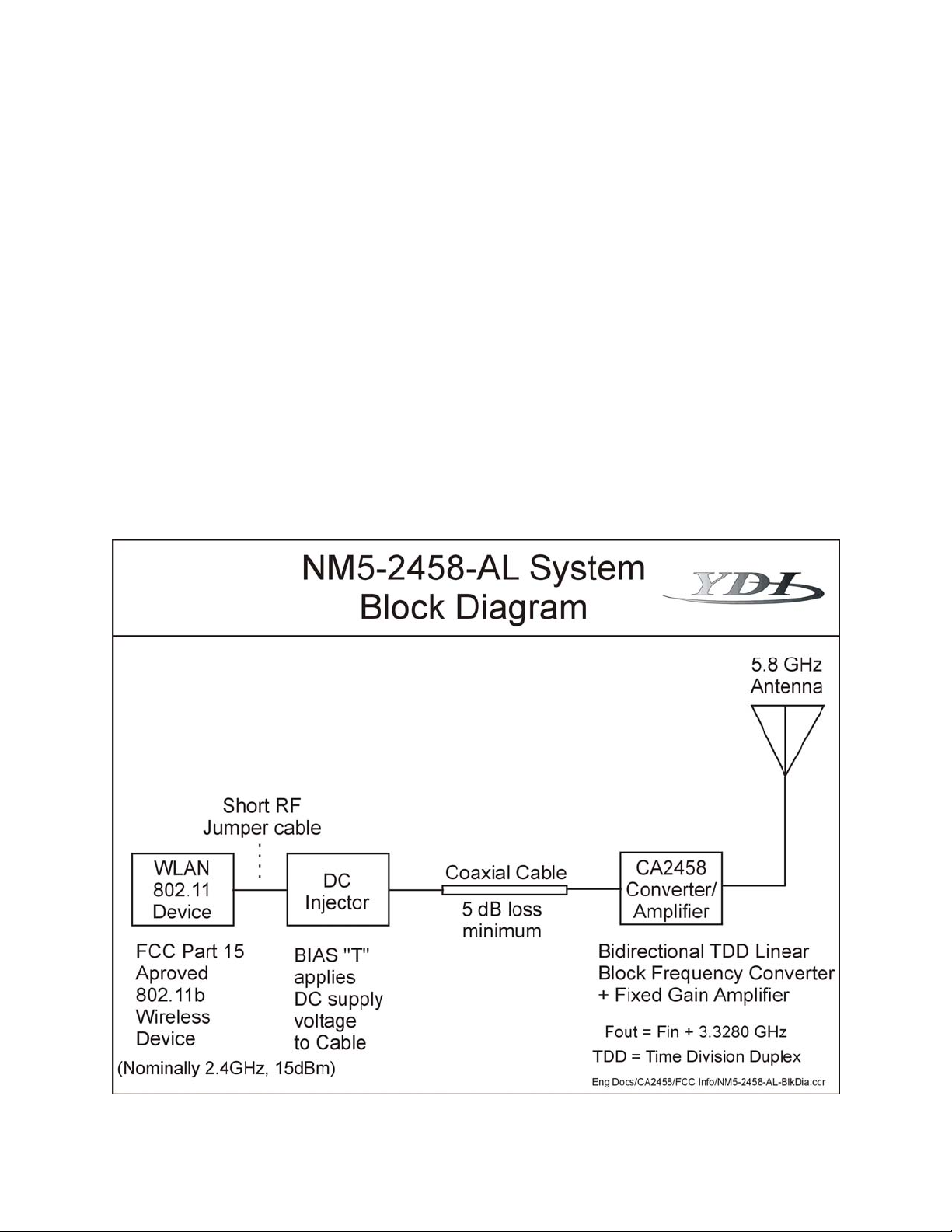
The CA2458 Converter/Amplifier (Converter or CA2458) outdoor unit provides bidirectional linear frequency block conversion (translation) from the 2.4 GHz band to the
5.8 GHz band. As a system, it allows the use of existing 2.4 GHz WLAN equipment on
the 5.8 GHz band. The Local Oscillator (LO) operates at 3.328 GHz. This means a
2.412 GHz signal will go out over the air at 5.740 GHz. Currently, the 5.8 GHz band
provides relief from interference that is present on 2.4 GHz in many geographic areas
and also allows the use of this band for backbone or backhaul use.
All functions of the CA2458 ODU are transparent to the user. No adjustments of any
kind are required. Channel assignment and network set-up are both performed at the
radio card (or access point).
Installation of the CA2458 requires outdoor mounting of the Converter (at the antenna)
and indoor installation of the WLAN card, DC Injector and power supply. Coaxial cable
carries both DC power and the RF signal from the DC Injector to the Converter. All
signals passing between the DC injector and Converter are at a frequency of 2.4 GHz to
minimize cable attenuation.
1
2.0 Converter (ODU) Features
• Transmit input levels from +3 dBm to +10 dBm
• 14 dB transmitter conversion power gain
• 12 dB receive conversion gain
• RX preamp noise figure 4.5 dB (typical)
• Mast mounted weatherproof cast aluminum case
• DC power carried up through the transmission cable
• Power and transmit LEDs on both the Converter and the DC Power Injector
• Built-in lightning protection
• DC surge protection
• Heavy duty N-type connectors
• One-year warranty
• Made in the U.S.A
2
Converter/Amplifier System
3
 Loading...