


Version 1.0 February 2004 MNL-500224-001

Link CX-24 User’s Manual
This document applies to the YDI Wireless (YDI) release of the Link CX-24 product line and to all
subsequent versions and releases of the hardware or software unless otherwise indicated in a new
version or an update package for this edition. The products described in this document are products of
YDI Wireless or its licensers.
YDI Wireless reserves the right to make changes to any products described herein at any time without
notice. YDI Wireless does not assume any responsibility or liability arising out of the application or use of
any product described herein, except as expressly agreed to in writing by YDI Wireless, nor does the
purchase or use of a product from YDI Wireless convey a license under any patent rights, copyrights,
trademark rights, or any other of the intellectual property rights of YDI Wireless or third parties.
Use, duplication, or disclosure by the U.S. Government is subject to restrictions of FAR 52.227-14 (g) (2)
(6/87) and FAR 52.227-19 (6/87), or DFAR 252.227-7015 (b) (6/95) and DFAR 227.7202-3 (a).
The software described in this document is furnished under a license agreement or nondisclosure
agreement. The software may be used or copied only in accordance with the terms of the agreement. It is
a violation of YDI Wireless proprietary rights to copy the software on any medium except as specifically
allowed in the license or nondisclosure agreement.
The Link CX-24 product line is covered by one or more of the following United States Patents: No.
5,577,029, No. 5,654,968, No. 5,682,403, No. 5,721,735, No. 5,734,699, No. 5,734,979, No. 5,761,195,
No. 5,781,582, No. 5,818,824, No. 5,842,138, No. 5,887,256, No. 5,953,651, No. 5,957,464, No.
5,999,813, No. 6,070,071, No. 6,078,823, No. 6,081,716, No. 6,101,400, No. 6,169,907, No. 6,173,177,
No. 6,212,395, No. 6,269,255, No. USP D 391,967, No. USP D 391,968, No. USP D 397,693.
Changes or modifications not expressly approved by YDI Wireless in writing can void the user’s authority
to operate this equipment.
IMPORTANT OPERATING NOTICE
This device is to be exclusively used for fixed point-to-point operation with directional
antennas.
PROFESSIONAL INSTALLATION REQUIRED
The Link CX-24 must be installed as a system by experienced antenna installation
professionals who are familiar with Radio Frequency (RF) issues such as gains and
losses, as well as local building and safety codes. Failure to do so will void the product
warranty and may expose the end user to excessive RF hazard.
Regulations regarding maximum antenna gains, power output and maximum permissible
exposure vary from country to country. It is the responsibility of the end user to operate
within the limits of these regulations and to ensure that the professional installers who
install this device are aware of these regulations. All antennas are intended to be installed
outdoors.
Version 1.0 Page i February 2004

Link CX-24 User’s Manual
©
I
MICROWAVE RADIO RADIATION WARNING
When installed properly, the Link CX-24 radio equipment complies with the limits for
human exposure to radio frequency (RF) fields adopted by the Federal Communications
Commission (FCC). All YDI Wireless microwave radio equipment is designed so that
under normal working conditions, microwave radiation directly from the radio is negligible
when compared with the permissible limit of continuous daily exposure recommended in
the United States by ANSI/IEEE C95.1-1991 (R1997), Safety Levels with Respect to
Human Exposure to Radio Frequency Electromagnetic Fields, 3 kHz to 300 GHz.
Microwave signal levels that give rise to hazardous radiation levels can exist within
transmitter power amplifiers, associated RF multiplexers, and antenna systems. Never
look into the front of an open RF connection or RF antenna as eyes are particularly
vulnerable to radiation. Do not
disconnect RF coaxial connectors, open microwave units,
or break down any microwave screening while the radio equipment is operating.
FCC NOTICE
This device complies with part 15 of the FCC rules. Operation is subject to the following two
conditions:
1. This device may not cause harmful interference, and
2. This device must accept any interference received, including interference that may cause
undesired operation.
* Note: The manufacturer is not responsible for any radio or TV interference caused by
unauthorized modifications to this equipment. Such modifications could void the user's
authority to operate the equipment.
These products are labeled with one of the following FCC ID numbers:
FCC ID: NM5-CX-DS3-ETH-24
2004 YDI Wireless. All Rights Reserved. No part or parts of this document may be reproduced,
translated, stored in any electronic retrieval system or transmitted, in any form or by any means,
electronic, mechanical, photocopied, recorded or otherwise, without the prior written permission of YD
Wireless.
Version 1.0 Page ii February 2004

Link CX-24 User’s Manual
TABLE OF CONTENTS
Section 1 Overview 1
1.1 Description ....................................................................................................................................1
1.2 Regulatory Information .................................................................................................................. 1
1.3 Products ........................................................................................................................................ 1
1.4 Applications ...................................................................................................................................2
1.5 System Overview ..........................................................................................................................2
1.6 Features ........................................................................................................................................4
1.7 Link CX-24 Basic Structure ...........................................................................................................4
1.8 Typical Applications .................................................................................................................... 11
1.9 Specifications .............................................................................................................................. 11
Section 2 Installation 12
2.1 Introduction .................................................................................................................................12
2.2 Planning a Link CX-24 Network ..................................................................................................12
2.3 Site Planning ............................................................................................................................... 13
2.4 Planning Element and Network Management Ethernet Links ....................................................14
2.5 Planning DS-3 Links....................................................................................................................15
2.6 Power Planning ...........................................................................................................................15
2.7 Transmit Power Planning ............................................................................................................15
2.8 Radio Link Planning ....................................................................................................................16
2.9 Before Installing ..........................................................................................................................18
2.10 Initial Configuration ..................................................................................................................... 21
2.11 Mounting the Link CX-24............................................................................................................. 30
2.13 Completing the Link CX-24 Installation....................................................................................... 33
2.14 Aligning the Antenna ................................................................................................................... 35
2.15 Acceptance Testing.....................................................................................................................37
2.16 Final Link CX-24 Configuration ................................................................................................... 40
2.17 Updating the Link CX-24 Software.............................................................................................. 41
Section 3 Monitoring and Trend Analysis 43
3.1 Built-In Web Server Interface......................................................................................................43
3.2 SNMP Network and Element Management Systems .................................................................43
Section 4 Troubleshooting the Link CX-24 45
4.1 Troubleshooting Tables............................................................................................................... 45
4.2 Using the Link CX-24 LEDs ........................................................................................................45
4.3 Using RSSI..................................................................................................................................45
4.4 Using a Web Browser .................................................................................................................46
4.5 Customer Support Services ........................................................................................................ 46
Appendix A - Interface Cable Pinouts 47
Appendix B - Technical Specifications 49
Appendix C - Using the Web-Based GUI User Interface 52
C-1 Web Browser Requirements.......................................................................................................... 52
C-2 Connecting A Web Browser........................................................................................................... 52
C-3 Accessing the Link CX-24 Web Pages ..........................................................................................52
C-4 Link CX-24 Web Pages..................................................................................................................52
Version 1.0 Page iii February 2004

Link CX-24 User’s Manual
Appendix D - Grounding and Lightning Protection 58
D-1 Overview ........................................................................................................................................ 58
D-2 Grounding ......................................................................................................................................58
D-3 Lightning Protection .......................................................................................................................59
Appendix E - Enterprise MIBs and Traps 61
E-1 Enterprise MIBs..............................................................................................................................61
E-2 Enterprise Traps.............................................................................................................................79
Bibliography 80
FIGURES
Figure 1.1 – Link CX-24 Power Supply ..................................................................................................2
Figure 1.2 – Typical Radio Link Configurations......................................................................................3
Figure 1.3 – Link CX-24 Star Network.................................................................................................... 3
Figure 1.4 – Link CX-24 Interface Connectors and Indicators ...............................................................5
Figure 1.5 – Integral Antenna and Link CX-24 Radio............................................................................. 7
Figure 2.1 – Preventing Multi-path Fading from Ground-Level Surfaces .............................................13
Figure 2.2 – Typical EMS/NMS Ethernet Connections ........................................................................15
Figure 2.3 – Link CX-24 Orderable Parts .............................................................................................20
Figure 2.4a – Link CX-24 Configuration Setup ..................................................................................... 22
Figure 2.4b – Link CX-24 Positive-Ground Power Connections ..........................................................23
Figure 2.4c – Link CX-24 Negative-Ground Power Connections ......................................................... 23
Figure 2.5 – Typical DS-3 Link CX-24 Monitor Web Page ...................................................................24
Figure 2.6 – Typical Ethernet Link CX-24 Monitor Web Page.............................................................. 25
Figure 2.7 – Typical DS-3 Link CX-24 Commission Radio Web Page................................................. 25
Figure 2.8 – Typical Ethernet Link CX-24 Commission Radio Web Page ...........................................26
Figure 2.9 – Typical DS-3 Link CX-24 Commission Manager Web Page ............................................ 27
Figure 2.10 – Typical Ethernet Link CX-24 Commission Manager Web Page ....................................28
Figure 2.11 – Typical Link CX-24 DS-3 Test Web Page ......................................................................29
Figure 2.12 – Link CX-24 Mounting Components ................................................................................ 30
Version 1.0 Page iv February 2004

Link CX-24 User’s Manual
Figure 2.13 – Setting the Link CX-24 Polarization – Vertical Polarization Shown ...............................31
Figure 2.14 – Detail Showing Assembly of Pole Mounting Bracket to Unit (Vertical Polarization) ......32
Figure 2.15 – Attaching the Link CX-24 Unit to the Pole...................................................................... 33
Figure 2.16 – Connecting an Earth Ground to the Link CX-24............................................................. 34
Figure 2.17 – Final Line-of-Sight Adjustment and Signal Optimization ................................................36
Figure 2.18 – Typical DS-3 Update Software Web Page ..................................................................... 41
Figure 2.19 – Typical Ethernet Update Software Web Page................................................................ 41
Figure C.1 – Link CX-24 Login Window (all models)............................................................................ 52
Figure C.2 – Link CX-24 DS-3 Monitor Web Page ............................................................................... 53
Figure C.3 – Link CX-24 DS-3 Commission Radio Web Page............................................................. 53
Figure C.4 – Link CX-24 DS-3 Commission Manager Web Page........................................................ 54
Figure C.5 – Link CX-24 DS-3 Test Web Page .................................................................................... 55
Figure C.6 – Link CX-24 DS-3 Update Software Web Page ................................................................ 55
Figure C.7 – Link CX-24 Ethernet Monitor Web Page .........................................................................56
Figure C.8 – Link CX-24 Ethernet Commission Radio Web Page .......................................................56
Figure C.9 – Link CX-24 Ethernet Commission Manager Web Page ..................................................57
Figure C.10 – Link CX-24 Ethernet Test Web Page ............................................................................ 57
Figure C.11 – Link CX-24 Ethernet Update Software Web Page......................................................... 57
Version 1.0 Page v February 2004

Link CX-24 User’s Manual
TABLES
Table 1.1 – Link CX-24 Models ..............................................................................................................4
Table 1.2 – Link CX-24 Interface Connectors and Indicators................................................................. 6
Table 2.1 – Maximum Power Output by Model Configuration .............................................................. 16
Table 2.2 – Radio Link Planning Worksheet ........................................................................................16
Table 2.2 – Radio Link Planning Worksheet (continued) .....................................................................17
Table 2.2 – Radio Link Planning Worksheet (continued) .....................................................................18
Table 2.3 – Link CX-24 Radio Orderable Parts ....................................................................................20
Table 2.4 – Required Installation Tools ................................................................................................ 21
Table 2.5 – Physical Installation Checklist ...........................................................................................37
Table 2.6 – Electrical Connection Checklist ......................................................................................... 38
Table 2.7 – DS-3 Internal Circuit and Radio Link Checklist ................................................................. 39
Table 2.8 – Ethernet Internal Circuit and Radio Link Checklist ............................................................ 39
Table 4.1 – Symptoms and Probable Causes ...................................................................................... 45
Table 4.2 – LEDs and Alarm Indication Modes ....................................................................................45
Table A.1 – DS-3 Data Cables .............................................................................................................47
Table A.2 – 10/100 Ethernet Data or Control Cable............................................................................. 47
Table A.3 – DC Power Cable................................................................................................................47
Table A.4 – 10/100 Ethernet Crossover Cable.....................................................................................48
Table A.5 – RS-232 CLI Craft PC Cable ..............................................................................................48
Table B.1 – Link CX-24 DS-3 or Ethernet Version (24 GHz) ...............................................................49
Table B.1 – Link CX-24 DS-3 or Ethernet Version (24GHz) (continued) .............................................50
Table B.2 – Integral Reflector Antenna ................................................................................................51
Version 1.0 Page vi February 2004

Link CX-24 User’s Manual
Section 1
Overview
1.1 Description
This manual is intended for the technical personnel who will install and operate the Link CX-24. Such
personnel are typically experienced and skilled technicians familiar with on site, physical installation and
connection of equipment, including maintenance work. It is also intended for system administration
personnel performing initial configuration and subsequent system reconfiguration, as well as current
system maintenance activities.
1.2 Regulatory Information
1.2.1 FCC Compliance
The Link CX-24 is FCC certified for use in the 24 GHz unlicensed band in the United States.
24GHz (24.05-24.250 GHz)
When deployed in an area regulated by the FCC, Link CX-24 radios operate under the FCC Part 15.249
band regulations for intentional radiators in a point-to-point configuration. The Link CX-24 radios are
equipped with an integral antenna.
1.2.2 Other Regulation Compliance
Other countries have varying RF licensing and operating requirements, and it is imperative that operators
and professional installers ensure that the Link CX-24 is configured and installed per regional regulations.
1.3 Products
The Link CX-24 product is a cost-effective, all-outdoor, pole-mounted, high-capacity, line-of-sight (LOS)
digital radio transmission system, operating in the license-exempt 24.05-24.250 GHz (24GHz) frequency
band. The Link CX-24 can be used for the following applications: point-to-point or building-to-building,
WLL (wireless local loop), backup solutions, temporary links, and mesh cellular backhaul.
• The Link CX-24 DS-3 and 10/100 versions conform to the FCC (Federal Communications
Commission) Part 15.249 It operates at up to 0 dBm average transmit power, and is intended for
medium-distance use.
The Link CX-24 provides either a standard DS-3 (44.736 Mbps) interface adhering to Bellcore GR-499CORE (DSX-3) standards, or provide two Ethernet 10/100Base-T interfaces adhering to IEEE 802.3
standards, with a combined nominal line rate of 45 Mbps.
Each Link CX-24 is powered by a 110/220 VAC to 48 VDC power supply (see Figure 1.1).
Version 1.0 Page 1 February 2004

Link CX-24 User’s Manual
Figure 1.1 – Link CX-24 Power Supply
1.4 Applications
The Link CX-24 product line is designed to serve the following communications markets:
• Internet Access and Backhaul Systems: Used by Internet Service Providers (ISPs).
• Private Networks: Wireless Bridged LANs and WANs.
• PCS/PCN and Cellular Networks: High-speed links between base stations.
• Wireless Local Loop Networks: Fixed wireless, used by Local Exchange Carriers (LECs).
• Business Bypass or Local Exchange Bypass: Provided by Competitive Access Providers (CAPs)
and Competitive Local Exchange Carriers (CLECs).
1.5 System Overview
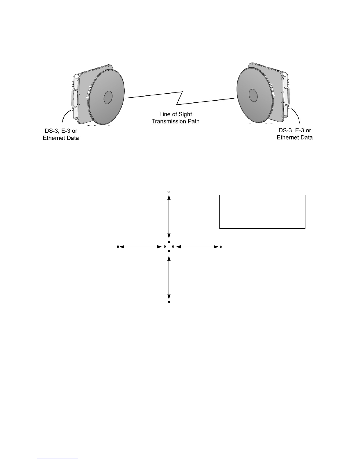
Each Link CX-24 consists of a Link CX-24 radio, with integral antenna as shown in Figure 1.2, along with
external power and data cabling. In a typical installation, the Link CX-24 radio with integral antenna is
mounted outdoors, usually on a tower or building.
See Figure 1.2. A radio system, or link, contains two Link CX-24 radios with integral antenna, installed at
each end of the link, separated by a line of sight transmission path. Frequency band, terrain, actual lineof-sight and environmental conditions influence the range of operation and path performance.
The Link CX-24 carries one full-duplex DS-3, or Ethernet channel, and is powered by a 48-watt external
48 VDC power supply.
Version 1.0 Page 2 February 2004
Link CX-24 User’s Manual
Figure 1.2 – Typical Radio Link Configurations
Because the Link CX-24 offers both high and low channels in a single band, and can be installed with
horizontal or vertical polarization, up to four Link CX-24 radios can be mounted at each hub, or node, to
form part of a star or mesh network. See Figure 1.3.
Figure 1.3 – Link CX-24 Star Network
1H 24
This is one sample
configuration. Many other
combinations of channels
and frequencies are possible.
2V 24 2H 24
1H = Channel 1,
Horizontal
1V 24
2V = Channel 2,
Vertical
Version 1.0 Page 3 February 2004

Link CX-24 User’s Manual
1.6 Features
The Link CX-24 offers the following features:
• Robust all-outdoor enclosure.
• Integral antenna.
• Sturdy radio mounting systems for quick, accurate and reliable integral antenna alignment.
• Operates in the license-exempt 24.05-24.250GHz (24GHz) band.
• Full-duplex transmission:
• DS-3 (DSX-3, per Bellcore GR-499-CORE)
• Ethernet 10/100Base-T (per IEEE 802.3)
• Easy configuration, installation, operation, and maintenance.
• Integral web server for configuring, operating, and monitoring using an HTML-based web browser
GUI.
• Ethernet interface used with NMSs (Network Management Systems) or EMSs (Element
Management Systems) using SNMP (Simple Network Management Protocol) traps. Supports
MIB-II (Management Information Base II) and YDI Wireless enterprise MIB.
• ATPC (Automatic Transmit Power Control).
• Self Test, BER test mode, RF and digital loop-backs.
• Reed Salomon Forward Error Correction (FEC).
• Operating and backup software versions contained in Link CX-24 memory, operator-selectable.
1.7 Link CX-24 Basic Structure
1.7.1 Radio Links
Each radio link includes two Link CX-24 terminals. Each terminal consists of a Link CX-24 radio with an
integral 12” diameter reflector antenna. Generally, the Link CX-24 terminals are mounted outdoors on a
tower or building.
1.7.2 Data Stream
The DS-3 or Ethernet data signals enter the Link CX-24 and are modulated into the RF data stream. The
RF radio signal radiates from the local antenna and propagates to the remote antenna. At the remote
terminal, the received signal is demodulated and de-multiplexed, separating the payload data and the
overhead management data.
1.7.3 Link CX-24 Models
The Link CX-24 is manufactured in two configurations, namely versions with DS-3 or Ethernet carried
over the 24GHz link.
Link CX-24 models are described in Table 1.1.
Table 1.1 – Link CX-24 Models
Model
CX-DS3-24-LO
CX-DS3-24-HI
CX-ETH-24-LO
CX-ETH-24-HI
Transmit
Band
High
Low
High
Low
Frequency
Band
24.05-24.250 GHz DS-3 Integral 12” reflector
24.05-24.250 GHz
Link
Carries
Ethernet
(45 Mbps)
Antenna
Integral 12” reflector
Version 1.0 Page 4 February 2004

Link CX-24 User’s Manual
1.7.4 Mounting and Antenna Alignment
To ensure proper mounting and antenna alignment, YDI sells a mounting bracket designed for use with
the Link CX-24. The single bracket mounts one Link CX-24. The bracket is designed to provide rugged
mounting for the Link CX-24, while allowing fine adjustment for antenna alignment.
1.7.5 Interface Connectors and Indicators
See Figure 1.4 for a view of the Link CX-24 external connectors and indicators. The Link CX-24
connectors and indicators are described in Table 1.2.
Figure 1.4 – Link CX-24 Interface Connectors and Indicators
Version 1.0 Page 5 February 2004

Link CX-24 User’s Manual
Table 1.2 – Link CX-24 Interface Connectors and Indicators
No. Name Component Description From Note
1 POWER
Male 4-Pin
Circular
Connector
Power input
plug
Power Supply Accepts ±21 to ±60 VDC
Female 4-Pin
2 CRAFT
Circular
Connector
3 RSSI
4 OUT
5 IN
Female BNC
Connector
Female TNC
Connector
Female TNC
Connector
Female 4-Pin
6 ETHERNET 2
Circular
Connector
Female 4-Pin
7 ETHERNET 1
Circular
Connector
PWR/LCL ALM Green LED
RF LINK Green LED
DATA Green LED DS-3 Status
8
RS-232
receptacle
Receive Signal
Level Indicator
DS-3 data from
the radio link
DS-3 data to
the radio link
10/100Base-T
transmit and
receive
receptacle
10/100Base-T
transmit and
receive
receptacle
Power/Local
Alarm Status
Radio Link
Status
ENET 2 Green LED Ethernet Status
ENET 1 Green LED Ethernet Status
Note: For connector pin-outs, refer to Appendix A.
Asynchronous
laptop port
Voltmeter
DS-3 data
equipment
DS-3 data
equipment
Ethernet
equipment
Ethernet
equipment
--
1200 to 115,200 baud,
used only for tech support
troubleshooting
Verifies RF signal strength,
used to align antenna
--
--
For Ethernet data or link to
SNMP or Web manager,
or use to daisy-chain
Ethernet port to next Link
CX-24 in cascade
(Same as ETHERNET 2)
ON = Power OK, no alarm,
Flashing = Local alarm,
OFF = Power off.
ON = Rcv. OK,
OFF = Link Alarm.
ON = OK (no LOS),
OFF = LOS.
ON = OK,
Flashing = data,
OFF = No conn.
ON = OK,
Flashing = data,
OFF = No conn.
Version 1.0 Page 6 February 2004
Link CX-24 User’s Manual
1.7.6 Cables
To ensure longevity in an outdoor environment, YDI sells various cables designed for use with the Link
CX-24.YDI offers the following weather-resistant cables:
• DS-3, Ethernet data cables and the power cables are offered in 25 m (82 ft.), 50 m (164 ft.), and
100 m (328 ft.) lengths.
• A 6 m (19.7 ft.) Ethernet cable is available to route the Ethernet signal between two Link CX-24 in
the same location, or when you are configuring the Link CX-24 from a Craft PC.
• A 6 m (19.7 ft.) RS-232 4-pin Circular-to-DB9 Craft cable is available to connect a Craft PC to a
Link CX-24 for future CLI applications.
All of the cables described above include weather-resistant connectors.
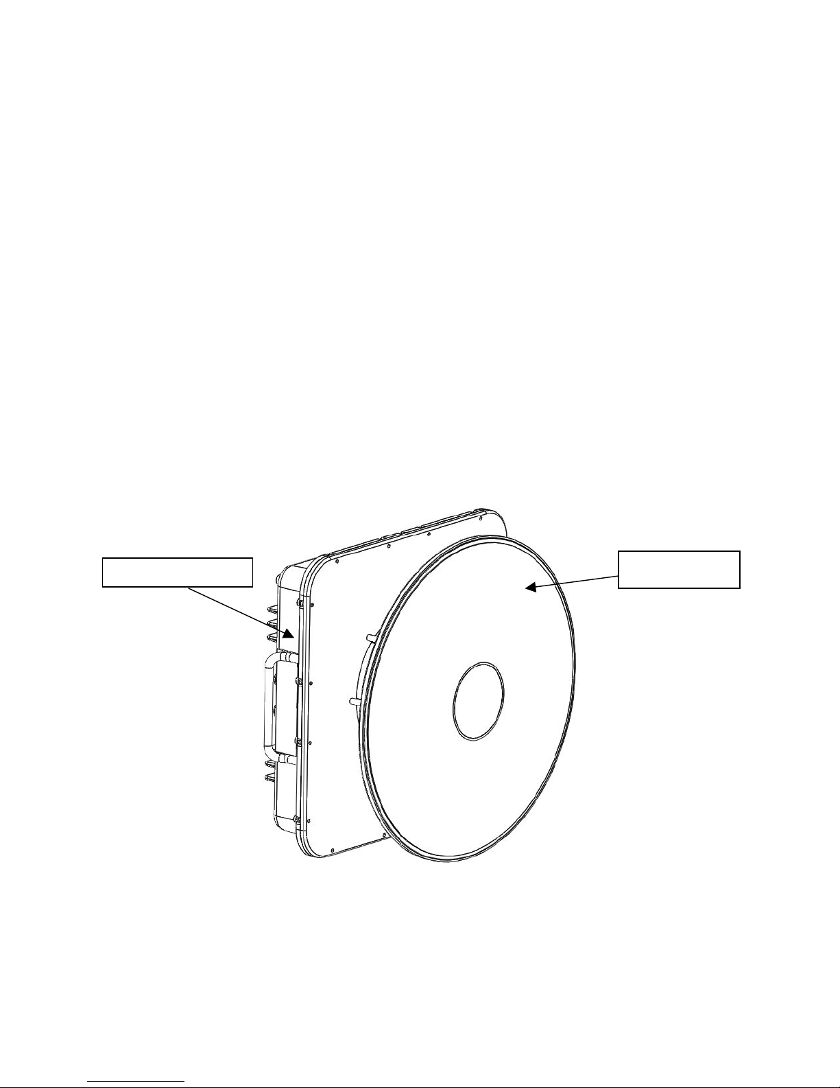
1.7.7 Integral Antenna
The integral antenna is a 12” diameter reflector antenna mounted directly on the Link CX-24 radio
chassis, as shown in Figure 1.5. All RF connections between the integral antenna and the Link CX-24
radio are made internally, eliminating the need for external coaxial cabling. Because the integral antenna
is sealed onto the Link CX-24 chassis, the Link CX-24 and integral antenna are mounted as a unit, and
share the same environmental protection. An arrow on the connector side of the Link CX-24 chassis
indicates the antenna polarization (either vertical or horizontal).
Link CX-24 radio
Figure 1.5 – Integral Antenna and Link CX-24 Radio
Integral antenna
Version 1.0 Page 7 February 2004
 Loading...