

Yazaki Kako FCU RC01 User Manual

Option Unit for
CREFORM AGC Drive Unit
Wireless Intersection Module
FCU-RC01

Contents
ontents
C
1 . About this instruction manual 4
Ü 1-1. Requirements for handling the manual 4
Ü 1-2. About symbols used in this manual 4
2 . About safety 5
3 . Overview of product 6
Ü 3-1. Software versions 6
Ü 3-2. About the wireless module 7
3-2-1. Features of the wireless module 7
3-2-2. Overview of the wireless module 8
4 . Accessories 8
Ü 4-1. Checklist 8
5 . Specifications 9
Ü 5-1. Specication table 9
6 . Part names and functions 10
Ü 6-1. Part names 10
Ü 6-2. Functions 10
6-2-1. Switches 10
6-2-2. Display 10
6-2-3. Antenna connection section 10
6-2-4. CN1 power connector 10
6-2-5. CN2 input/output connector 11
6-2-6. CN3 connector for parameter settings 11
Ü 6-3. Details of switches 12
6-3-1. DIP switch (SW1) 12
6-3-2. Rotary switches (RSW1 to 4) 13
Ü 6-4. Details of CN2 input/output 14
6-4-1. Input/output signals in the address sensor mode 15
6-4-2. Input/output signals in the RFID mode 16
6-4-3. Input/output signals in the ground station mode 17
6-4-4. Input/output signals in the external control mode 18
Ü 6-5. Details of display 19
7 . About related components 22
Ü 7-1. Wireless intersection module box FCP-RCB01-24 22
7-1-1. CN1 22
7-1-2. CN2 22
7-1-3. CN3 23
7-1-4. CN4 23
Ü 7-2. Wireless intersection module box FCP-RCB01-12 24
7-2-1. CN1 24
7-2-2. CN2 25
7-2-3. CN3 25
7-2-4. CN4 25
Ü 7-3. Pencil type antenna FCP-RCA01 26
Ü 7-4. Flanged antenna with bracket FCP-RCA02 26
Ü 7-5. Address sensor with bracket FCP-RCS01 27
7-5-1. Specications 27
Ü 7-6. RFID antenna with bracket FCP-RCS02 27
7-6-1. Specications 27
Ü 7-7. Address sensor with bracket for small Drive Unit FCP-RCS03 28
7-7-1. Specications 28
Ü 7-8. RFID antenna with bracket for small Drive Unit FCP-RCS04 28
7-8-1. Specications 28
Ü 7-9. Cable for 24 V Drive Unit FCP-RCC01-24 29
Ü 7-10. Cable for 12V Drive Unit FCP-RCC01-12 30
Ü 7-11. Cable for course 30 FCP-RCC02 31
Ü 7-12. Cable for small Drive Unit FCP-RCC03 32
Ü 7-13. Cable for address sensor FCP-RCC04 32
Ü 7-14. Cable for RFID antenna FCP-RCC05 33
Ü 7-15. Wireless intersection module setting cable FCP-RCC08 33
Ü 7-16. Address magnetic plate FCP-SMG01-* 34
7-16-1. Specications 34
Ü 7-17. ID tag FCP-TAG01 35
7-17-1. Specications 35
Ü 7-18. Wireless intersection module mounting bracket FCU-RCK06 36
Ü 7-19. Wireless intersection module mounting bracket FCU-RCK07 36
Ü 7-20. AC adapter FCP-RCP01 36
8 . Installation and connections 37
Ü 8-1. About installation place 37
Ü 8-2. About installation 39
8-2-1. Wireless Intersection Module 39
Ü 8-3. Connections and settings 41
8-3-1. Intersection is instructed by the address sensor when the 24 V forward type
Drive Unit is used.
8-3-2. Intersection is instructed by the RFID antenna when the 24 V forward type
Drive Unit is used.
8-3-3. Intersection is instructed by the course 30 unit when the 24 V forward type
Drive Unit is used.
8-3-4. Intersection is not instructed by the course 30 unit, but it is instructed by the
address sensor when the 24 V forward type Drive Unit is used.
8-3-5. Intersection is not instructed by the course 30 unit, but it is instructed by the
RFID antenna when the 24 V forward type Drive Unit is used.
8-3-6. Intersection is instructed by the course 30 unit when the 24 V forward/backward
type Drive Unit is used.
8-3-7. Intersection is not instructed by the course 30 unit, but it is instructed by the
address sensor when the 24 V forward/backward type Drive Unit is used.
8-3-8. Intersection is not instructed by the course 30 unit, but it is instructed by the
RFID antenna when the 24 V forward/backward type Drive Unit is used.
8-3-9. Intersection is instructed by the address sensor when the 12V forward type
Drive Unit is used.
8-3-10. Intersection is instructed by the RFID antenna when the 12V forward type
Drive Unit is used.
8-3-11. Intersection is instructed by the course 30 unit when the 12V forward type
Drive Unit is used.
8-3-12. Intersection is not instructed by the course 30 unit, but it is instructed by the
address sensor when the 12V forward type Drive Unit is used.
8-3-13. Intersection is not instructed by the course 30 unit, but it is instructed by the
RFID antenna when the 12V forward type Drive Unit is used.
8-3-14. Intersection is instructed by the course 30 unit when the 12V forward/back-
ward type Drive Unit is used.
8-3-15. Intersection is not instructed by the course 30 unit, but it is instructed by the
address sensor when the 12V forward/backward type Drive Unit is used.
8-3-16. Intersection is not instructed by the course 30 unit, but it is instructed by the
RFID antenna when the 12V forward/backward type Drive Unit is used.
8-3-17. Intersection is instructed by the address sensor when the small Drive Unit is
used.
8-3-18. Intersection is instructed by the RFID antenna when the small Drive Unit is
used.
8-3-19. Intersection control is performed using the ground station. 59
9 . Intersection 60
Ü 9-1. For address sensor 60
9-1-1. Layout of address magnetic plate 60
9-1-2. Installation of address sensor 60
9-1-3. Detection direction of address sensor 61
9-1-4. About installation of address magnetic plate 61
9-1-5. Forward type 62
9-1-6. Forward/backward type 63
9-1-7. Timing chart 64
Ü 9-2. For RFID antenna 65
9-2-1. Layout of ID tag 65
9-2-2. Installation of RFID antenna 65
9-2-3. Forward type 66
9-2-4. Forward/backward type 67
9-2-5. Timing chart 68
Ü 9-3. For course 30 unit 69
9-3-1. Forward type 69
9-3-2. Forward/backward type 70
41
42
43
44
45
46
47
48
49
50
51
52
53
54
55
56
57
58
- 2 -

9-3-3. Timing chart 72
Ü 9-4. For ground station 72
10. Wireless intersection module parameter settings 73
Ü 10-1. FCU-RC01 setup software FCU-RC01_Set 73
10-1-1. Operating conditions for FCU-RC01 setup software 73
10-1-2. Basic screen, and part names and functions 74
10-1-3. Connection and disconnection procedures 78
Ü 10-2. ID setting 79
10-2-1. Setting example 79
Ü 10-3. One shot pulse width setting 79
10-3-1. Setting example 79
Ü 10-4. Stop-Start delay setting 80
10-4-1. Setting example 80
Ü 10-5. Frequency CH setting 81
10-5-1. Setting example 81
Ü 10-6. Travel priority setting 82
10-6-1. Setting example 82
10-6-2. Address sensor mode 83
10-6-3. Timing chart 83
10-6-4. RFID mode 84
10-6-5. Timing chart 85
Ü 10-7. Ground station setting 85
10-7-1. Setting example 1 85
10-7-2. Setting example 2 86
10-7-3. Setting example 3 87
10-7-4. Setting example 4 88
10-7-5. Caution 89
Ü 10-8. Trigger setting 90
10-8-1. Setting example 90
10-8-2. Timing chart 91
Ü 10-9. Intersection operation setting 92
10-9-1. Setting example 92
Ü 10-10. Initialization 93
10-10-1. Procedures 93
Ü 10-11. Load or Save settings 94
10-11-1. Settings saving procedures 94
10-11-2. Settings loading procedures 95
11. External control mode 96
Ü 11-1. Settings 96
11-1-1. Wiring 96
11-1-1-1. Power supply 96
11-1-1-2. Input/output 97
11-1-2. Wiring example 98
11-1-3. Flow of control 99
11-1-3-1. AGV (1) passes through the intersection and AGV (2) waits. 99
11-1-3-2. AGV (3) waits while AGV (1) is passing and AGV (2) is waiting. 100
11-1-3-3. AGV (2) waits with the intersection top priority input turned ON while AGV (1)
is passing and AGV (3) is waiting.
11-1-3-4. AGV (1) passes through the intersection, AGV (2) waits, and SW1-4 of each
wireless intersection module is turned ON.
11-1-3-5. AGV (1) passes through the intersection, AGV (2) waits, and SW1-5 of each
wireless intersection module is turned ON.
12. Caution 103
13. Contents of warranty 103
Ü 13-1. Warranty period 103
Ü 13-2. Warranty coverage 103
14. Others 104
Ü 14-1. Precautions 104
Ü 14-2. Contacts 104
Contents
101
102
102
- 3 -
ê 1. About this instruction manual
1.
This instruction manual is prepared to control and use the wireless intersection module, that is an optional unit for the
Drive Unit, in a correct and safe manner and fully utilize its functions. This manual primarily describes the methods of
handling the wireless intersection module. For details about the Drive Unit main body, refer to the instruction manual
supplied with the Drive Unit.
1-1.
The instruction manual is a “part of the product” necessary to use the product. To operate the product in a safe and
correct manner, thoroughly read this instruction manual to fully understand its contents and strictly observe its guidance when operating the product. In addition, after reading the instruction manual, carefully store it in a safe place for
the period of appropriate time for future reference. Update the manual as newly revised documents are delivered and
dispose of the previous versions.
1-2.
To help users’ understanding, this manual uses two kinds of symbols in the main body of the document to describe
important points and supplemental contents.
bout this instruction manual
A
Requirements for handling the manual
About symbols used in this manual
Indicates contents where one must pay attention in the main body of the document.
Indicates useful information and provides operating tips.
To warn the users and prevent hazards, the following indications are provided to indicate possible hazards leading to
personal injury or damage to the equipment.
This denotes immediate hazards which will result in death or severe personal injury, if not avoided.
WARNING :
In addition, to prevent hazards, the following graphic warning symbols are used for safety-related items.
Prohibited action symbols
The actions are prohibited when the product is being operated. The action may be overlapped with the graphic
symbols to show the prohibition of more specic contents.
Example:
Alert symbols
The symbols show the conditions under which special attention is required such as ignition hazard or high temperature when the product is being operated. The action may be overlapped with the graphic symbol to alert the
user to more specic contents.
Example:
Fire is prohibited. Example: Touching is prohibited.
General alert Example: Corrosion alert
Action instruction symbols
The symbols are added when action is required in accordance with the instructions when the product is being
operated. The symbol illustrating the contents may be combined
to further show the contents of the instruction.
Example:
General instruction or action request
- 4 -
Example: Grounding instruction
ê 2. About safety
2.
Strictly observe the following safety precautions to prevent operating problems or malfunction of this product.
bout safety
A
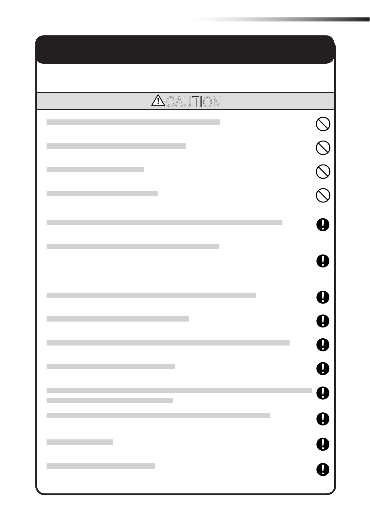
CAUTION
Do not install the antenna in a place surrounded by metallic members.
Install the antenna 200 mm or more away from the oor.
Do not apply any shock to the antenna.
Do not pull or bend the cable or cord forcibly.
Install the antennas at the highest possible positions where the antennas can be seen together.
Install the antenna so that it is not parallel to cables or metallic plates.
Install the antenna away from any cable, metallic plates, concrete, plasterboard, lumber, and wall surfac-
es as much as possible (300 mm or more).
Install the antennas of the different wireless units 2 m or more away from each other.
When installing the antenna, adjust the antenna direction.
Set the ID of the wireless intersection module so that it is not duplicated. Do not use duplicate IDs.
Set the ID to 900 to 999 in the ground station mode.
An incorrect approach may occur depending on the communication status. Widen the range of the obstacle
sensor as much as possible inside the intersection.
Use the wireless intersection modules with the same software version in the same system.
The wireless intersection modules with different software versions cannot be used.
Do not modify this product.
This product is intended for indoor use only.
Be sure to handle the product under the conditions dened in the specications.
- 5 -
ê 3. Overview of product
3.
O
This product is a wireless module that communicates in the 2.4 GHz band.
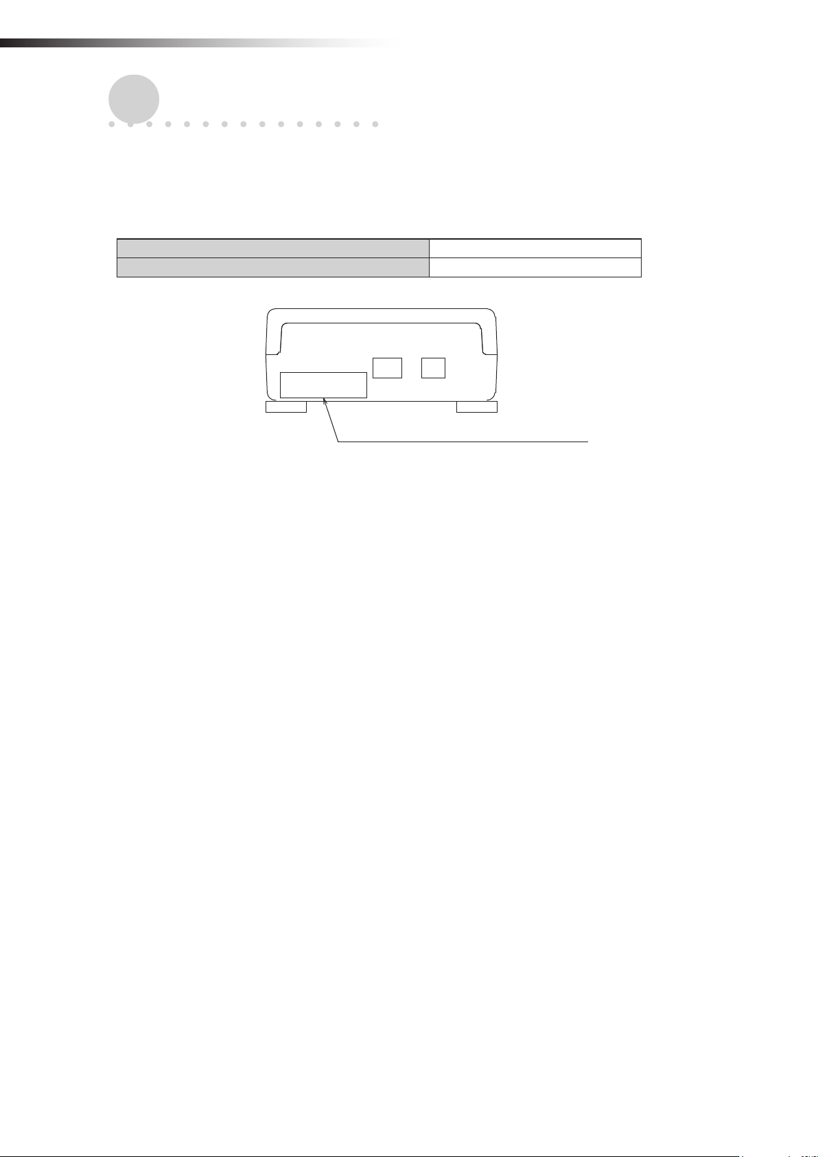
3-1.
This instruction manual supports the following software versions or later.
verview of product
Software versions
FCU-RC01 main unit software version App_v1.10.22
FCU-RC01 setup software version Ver. 0.1.9
Software version label affixing position
- 6 -
ê 4. Accessories
3-2.
About the wireless module
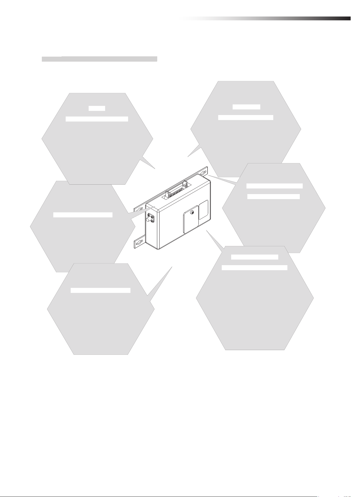
3-2-1. Features of the wireless module
Easy
intersection control
The wireless units communicate
with each other to determine whether passing through the intersection is
possible or not. Therefore, the AGV
does not need to perform the
intersection control.
Antenna selection
You can select a pencil type antenna
or anged antenna depending on the
application.
Multiple
operation modes
The address sensor mode, RFID mode,
ground station mode, and external con-
trol mode are available as operation
modes.
Radio frequency
channel change
You can select a radio frequency
from 15 channels. An optimal fre-
quency band without interference
can be easily selected.
Easy installation
The wireless intersection module
can be installed on a Creform pipe using
the wireless intersection module box
or wireless intersection module
mounting bracket.
Wireless com-
munication distance
The wireless communication
distance may vary depending on the
installation location (environment). The
following distance is used as a guide.
• Indoor placement with good visibility, About
15 m (Environment in which the antennas
can be seen together and are installed
at high positions, and there are no
obstacles around the antennas.)
Note: Field research is need-
ed.
- 7 -
ê 4. Accessories
3-2-2. Overview of the wireless module
• The wireless module units communicate with each other to perform the intersection control.
• Instructions regarding the entrance and exit of the intersection are sent to the wireless intersection modules by the
address sensor, RFID antenna, course 30 unit, and external unit that sends various output signals. In addition, the
wireless intersection modules installed on the AGVs communicate with each other to determine whether passing
through the intersection is possible or not.
Basically, the order of passing through the intersection is set in the order of arrivals.
• If the communication status is unstable due to a long distance of wireless communication or due to effects of
obstacles caused by the layout, install the wireless intersection module on the ground and use it in the ground
station mode. The radio wave then easily reaches and avoids the effects caused by obstructions.
One ground station can control four intersections.
• You can select the intersection control by connecting signals from the wireless intersection modules installed on
the AGVs with each other or the intersection control by sending inquiries to the ground station for each intersection
address.
For the intersection control by setting the wireless intersection modules to communicate with each other, up
to eight wireless intersection modules can be used for one intersection. (Total number of units that are passing through the intersection and units that are waiting at the same time. For example, one unit is passing
and seven units are waiting at the same time.) In addition, when the intersection control is performed using
the ground station, one ground station can control up to four intersections.
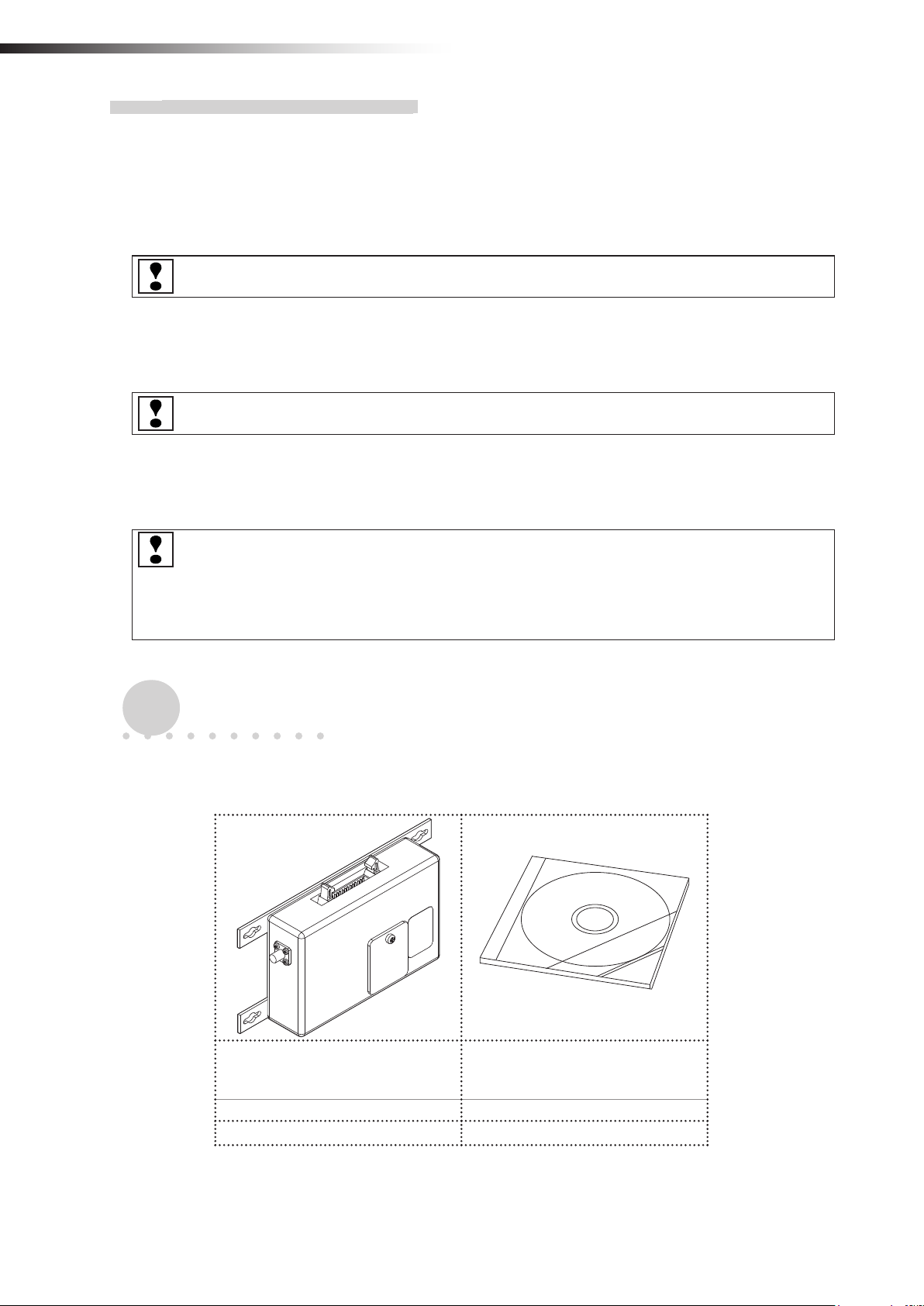
4.
4-1.
Use the checklist to check the contents of the product package you have received.
ccessories
A
Checklist
Wireless Intersection Module
FCU-RC01
1 unit 1 pc. (CD-ROM)
□ □
Note: When multiple units are ordered, one CD-ROM is supplied with one set.
- 8 -
This instruction manual and
parameter setup software
“FCU-RC01_Set”
ê 5. Specications
5.
S
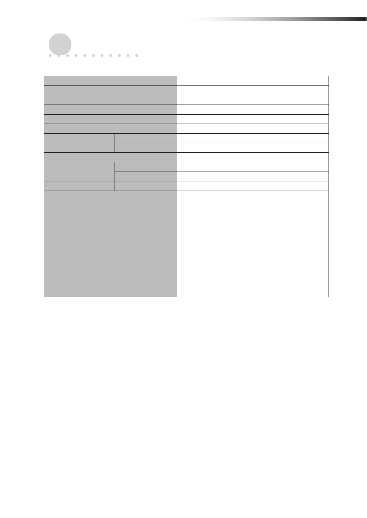
5-1.
Intersection control
using modules
pecications
Specication table
Product name Wireless Intersection Module
Model number FCU-RC01
Rated power supply voltage 24 V DC±10%
Power consumption 6 W or less
Body size 80 × 171 × 32 mm (excluding protrusions)
Weight 235 g
Environment
specications
Radio frequency band 2.4 GHz, 2405 to 2475 MHz
Input circuit
Output circuit Rated current 50 mA
Operating temperature -10 to 50ºC (No dew condensation or freezing allowed.)
Operating humidity 0 to 90% RH (No dew condensation allowed.)
Applied voltage 24 V DC
Rated current 10 mA
Number of control units
One ground station
Number of intersections
Up to eight units for one intersection.
One unit is passing and seven units are waiting.
Up to four intersections
Intersection control
using ground station
One ground station
Number of control units
For one intersection, one unit is passing through one
intersection and seven units are waiting.
For two intersections, one unit is passing through one
intersection and seven units are waiting.
For three intersections, one unit is passing through one
intersection and four units are waiting.
For four intersections, one unit is passing through one
intersection and three units are waiting.
- 9 -
ê 6. Part names and functions
6.
art names and functions
P
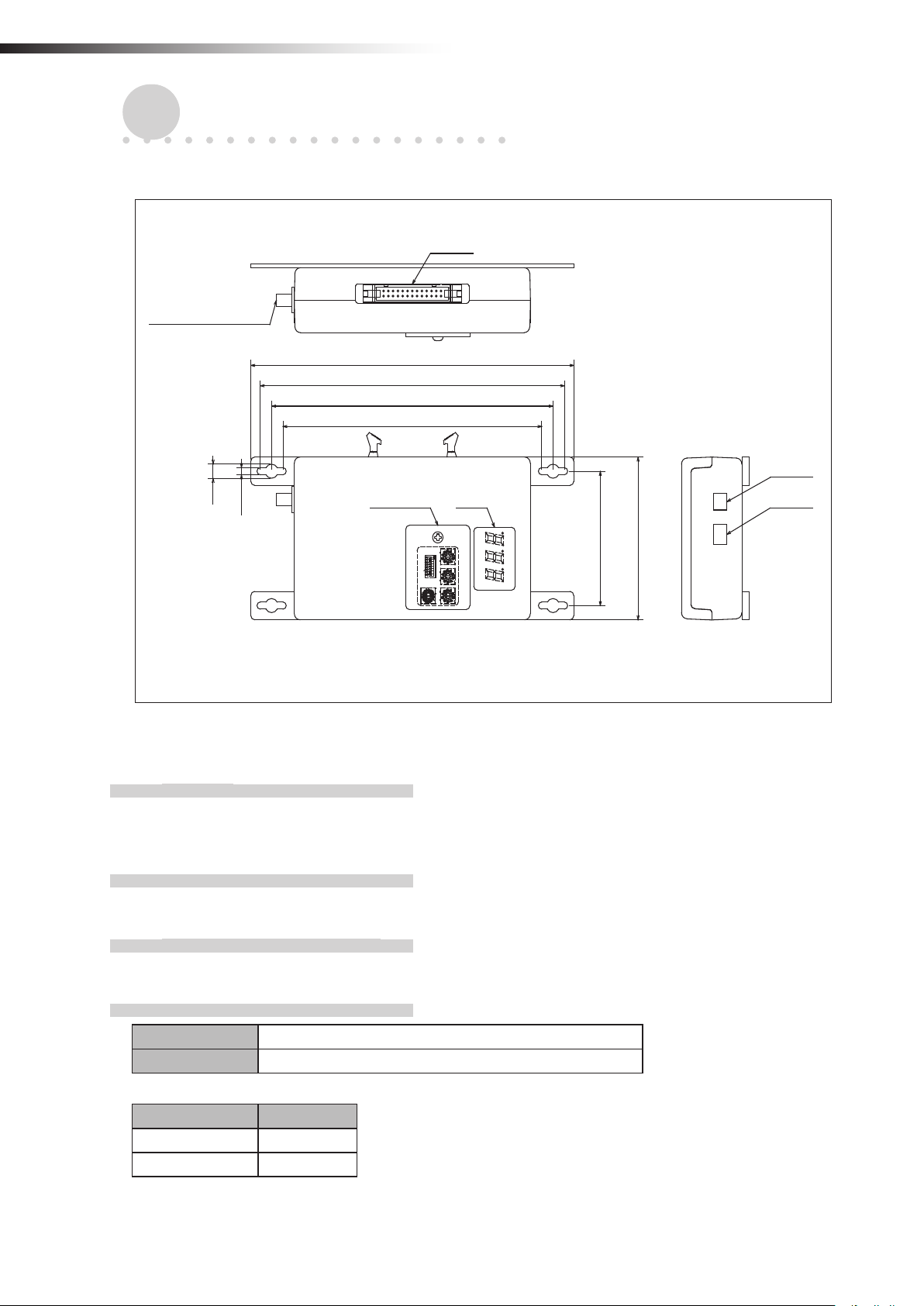
6-1.
Part names
Antenna connection
section
Unit: mm
CN2
171
161
149
137
CN1
7
3.5
3
2
4
1
5
ON
0
1
6
2345678
9
7
8
3
2
4
1
5
0
6
9
7
8
4
3
5
2
3
4
6
2
7
1
1
5
8
0
0
9
6
F
A
9
E
B
7
D
8
C
64
80
CN3Switch Display
FCU-RC01
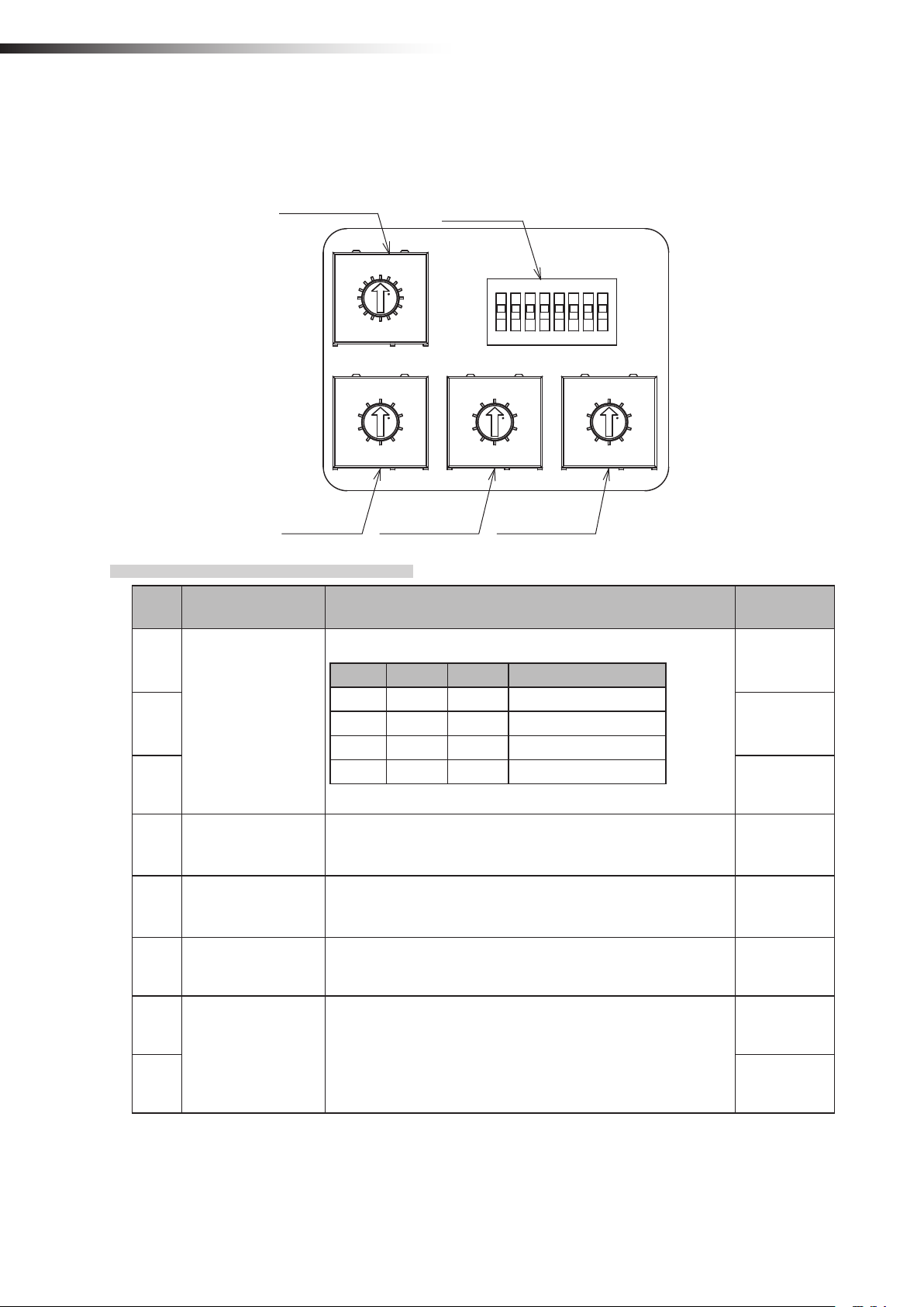
6-2.
6-2-1. Switches
6-2-2. Display
6-2-3. Antenna connection section
6-2-4. CN1 power connector
Functions
When you loosen the screw that secures the switch cover and slide it, you can operate the DIP switches and the
rotary switches for setting the wireless intersection module.
A 3-digit and 7-segment display indicates the status of the wireless intersection module.
Connect the antenna.
Connector S2B-XH-A connector for printed circuit board (JST)
Fitting connector XHP-2 connector for printed circuit board (JST)
Pin number Contents
1 +24 V
2 GND
- 10 -
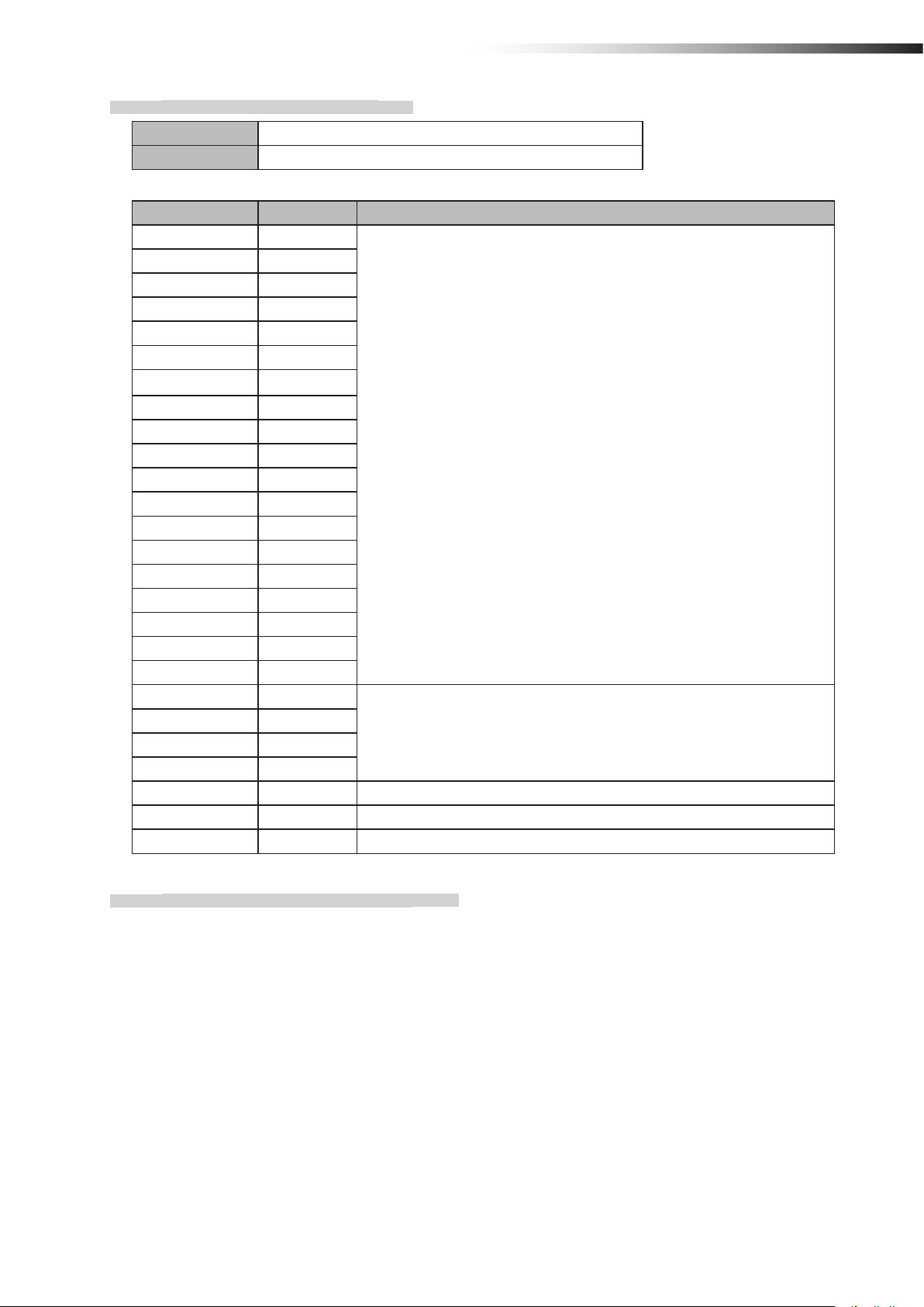
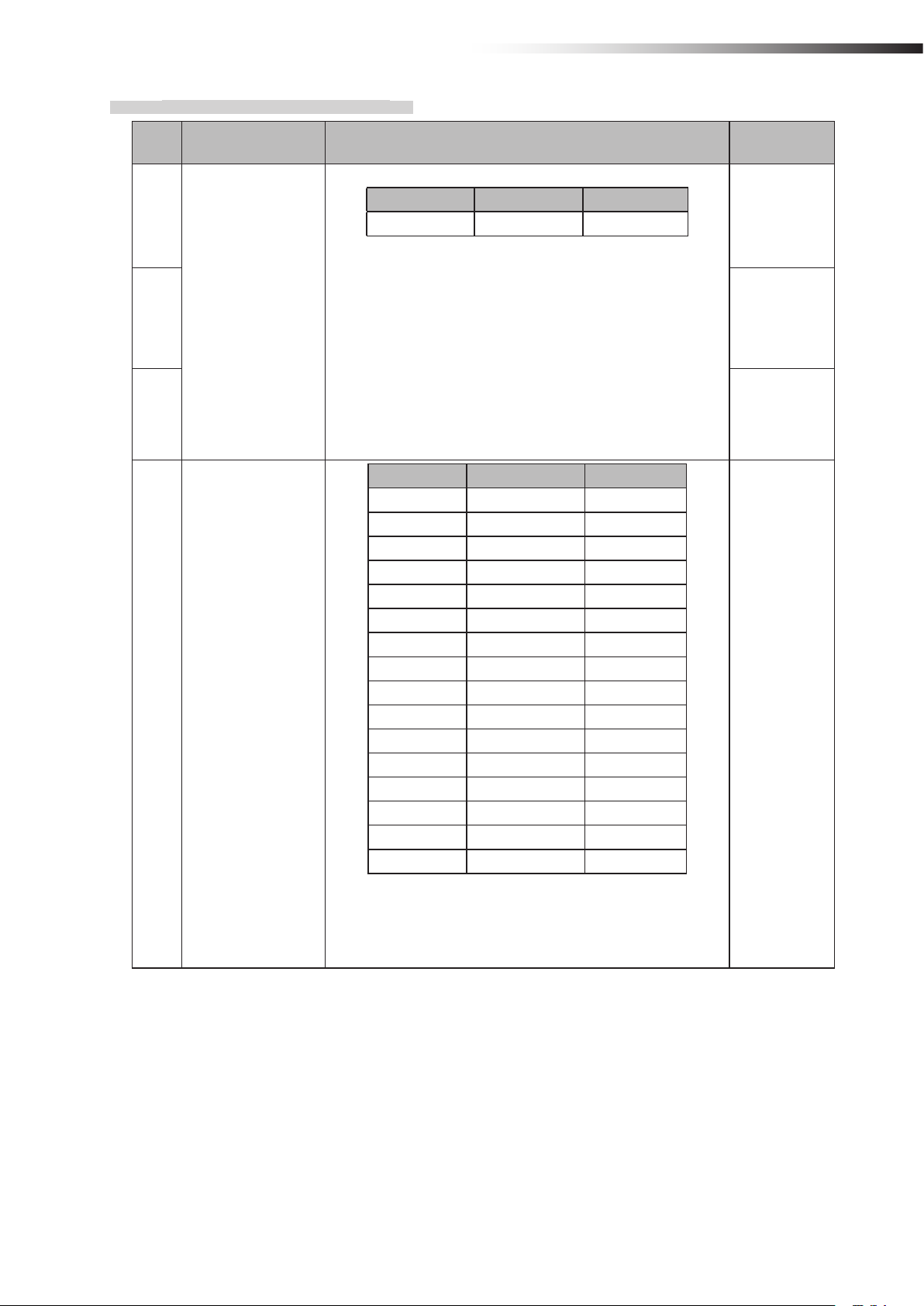
6-2-5. CN2 input/output connector
Connector MIL connector 26-core, male
Fitting connector MIL connector 26-core, female
Pin number Contents Remarks
1 OUT1
2 OUT2
3 OUT3
4 OUT4
5 OUT5
6 OUT6
7 IN1
8 IN2
9 IN3
10 IN4
11 IN5
12 IN6
13 IN7
14 IN8
15 IN9
16 IN10
17 IN11
18 IN12
19 IN13
20 +24 V
21 +24 V
22 GND
23 GND
24 TxD Dedicated for the RFID mode.
25 RxD Dedicated for the RFID mode.
26 SGND Dedicated for the RFID mode.
The input/output is switched using the operation mode setting of the DIP
switch (SW1).
Do not use these pins for supplying the power to an external device.
ê 6. Part names and functions
6-2-6. CN3 connector for parameter settings
This connector is used for the parameter settings of the wireless intersection module.
- 11 -
ê 6. Part names and functions
6-3.
Details of switches
When the settings of the switches (DIP switch and rotary switches) are changed, the settings take effect by turning OFF
the power and turning it ON again. Be sure to turn OFF the power, and then turn it ON again after changing the settings.
RSW4
RSW3
0
1
F
2
E
3
D
C
8
4
5
B
6
A
7
9
8
0
1
9
2
3
7
4
6
5
SW1
9
8
7
6
4 5 6 7 8
1 2 3
ON
0
1
2
3
4
5
0
1
9
8
2
7
3
4
6
5
RSW1RSW2
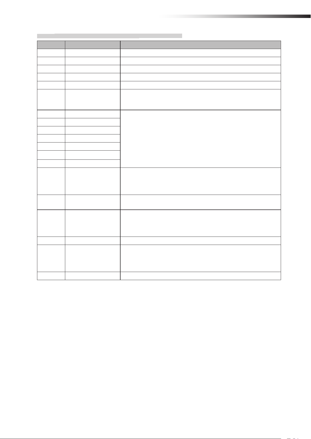
6-3-1. DIP switch (SW1)
No. Contents Details
1
Operation mode
2 OFF
settings
3 OFF
4 Start signal
5 Stop signal
6 PC setting
No. 3 No. 2 No. 1 Operation mode
OFF OFF OFF Address sensor
OFF OFF ON RFID
OFF ON OFF Ground station
OFF ON ON External control
In the external control mode
OFF: Level output
ON: One shot output
In the external control mode
OFF: Level output
ON: One shot output
ID and frequency CH settings using the FCU-RC01 setup
software are enabled.
Setting at
shipment
OFF
OFF
OFF
OFF
7
OFF
For maintenance Setting is disabled.
8 OFF
- 12 -
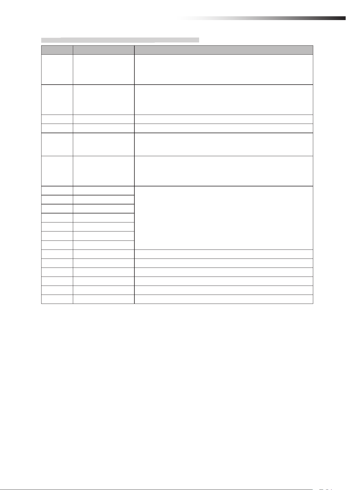
6-3-2. Rotary switches (RSW1 to 4)
ê 6. Part names and functions
No. Contents Details
No. 3 No. 2 No. 1
1
ID setting
2 0
3 0
Radio frequency
4
setting
Hundreds digit Tens digit Ones digit
• Set the ID of the wireless intersection module.
• The setting range of the wireless intersection module to be
installed on the AGV is 001 to 899.
• The setting range is 900 to 999 in the ground station mode.
• It is necessary to assign each wireless intersection module
a unique ID that is not duplicated.
• When the settings of RSW1 to 3 are 0, the ID setting using
the FCU-RC01 setup software is enabled.
No. 4 Frequency Channel
0 ― PC setting
1 2405 MHz 1
2 2410 MHz 2
3 2415 MHz 3
4 2420 MHz 4
5 2425 MHz 5
6 2430 MHz 6
7 2435 MHz 7
8 2440 MHz 8
9 2445 MHz 9
A 2450 MHz 10
B 2455 MHz 11
C 2460 MHz 12
D 2465 MHz 13
E 2470 MHz 14
F 2475 MHz 15
• When the setting of RSW4 is 0, the frequency CH setting
using the FCU-RC01 setup software is enabled.
Setting at
shipment
1
F
- 13 -

ê 6. Part names and functions
6-4.
The input/output of CN2 is switched using the operation mode setting of the DIP switch (SW1).
Signal Address sensor mode RFID mode Ground station mode External control mode
OUT1 Start Start Battery voltage drop Start
OUT2 Stop Stop AGV error Stop
OUT3 - - - OUT4 - - Normal (wireless unit) Normal (wireless unit)
OUT5 Passing Passing Passing Passing
OUT6 Pause Pause AGV arrival -
Details of CN2 input/output
IN1 Intersection address (1) - Start permission 1 Intersection address (1)
IN2 Intersection address (2) - Start permission 2 Intersection address (2)
IN3 Intersection address (4) - Start permission 3 Intersection address (4)
IN4 Intersection address (8) - Start permission 4 Intersection address (8)
IN5 Intersection address (16) - Start permission 5 Intersection address (16)
IN6 Intersection address (32) - Start permission 6 Intersection address (32)
IN7 Intersection address (64) - Start permission 7 Intersection address (64)
IN8 AGV error AGV error - AGV error
IN9 Read timing - - Intersection inquiry
IN10 AGV arrival AGV arrival - AGV arrival
IN11 - - - Intersection top priority
IN12 Battery voltage drop Battery voltage drop - Battery voltage drop
IN13 Reset Reset Reset Reset
- 14 -
6-4-1. Input/output signals in the address sensor mode
Contents Signal Description
OUT1 Start This signal is output to start the AGV that is waiting at the intersection.
OUT2 Stop This signal is output to stop the AGV at the intersection.
OUT3 - -
OUT4 - -
OUT5 Passing This signal is output while the AGV is passing through the intersection.
Inputting the pause signal to the AGV performs the intersection control with
OUT6 Pause
IN1 Intersection address (1)
IN2 Intersection address (2)
IN3 Intersection address (4)
IN4 Intersection address (8)
IN5 Intersection address (16)
IN6 Intersection address (32)
IN7 Intersection address (64)
IN8 AGV error
IN9 Read timing
IN10 AGV arrival
IN11 - -
IN12 Battery voltage drop
IN13 Reset This signal resets the intersection information.
the travel priority.
For details, see “10-6 Travel priority setting”.
Instructs the intersection address.
This signal is used by connecting the error output from the AGV.
When the input of the wireless intersection module that is passing through the
intersection turns ON during communication with the ground station, OUT2 of
the ground station turns ON.
This signal is output in one shot 10 ms after the output to instruct the intersection address has been sent from the address sensor.
This signal is used by connecting the arrival output from the AGV.
When the input of the wireless intersection module that is passing through the
intersection turns ON during communication with the ground station, OUT6 of
the ground station turns ON.
This signal is used by connecting the battery voltage drop output from the
AGV. When the input of the wireless intersection module that is passing
through the intersection turns ON during communication with the ground station, OUT1 of the ground station turns ON.
ê 6. Part names and functions
- 15 -

ê 6. Part names and functions
6-4-2. Input/output signals in the RFID mode
Contents Signal Description
OUT1 Start This signal is output to start the AGV that is waiting at the intersection.
OUT2 Stop This signal is output to stop the AGV at the intersection.
OUT3 - -
OUT4 - -
OUT5 Passing This signal is output while the AGV is passing through the intersection.
OUT6 Pause
IN1 - IN2 - IN3 - IN4 - IN5 - IN6 - IN7 - -
IN8 AGV error
Inputting the pause signal to the AGV performs the intersection control with
the travel priority.
For details, see “10-6 Travel priority setting”.
This signal is used by connecting the error output from the AGV.
When the input of the wireless intersection module that is passing through the
intersection turns ON during communication with the ground station, OUT2 of
the ground station turns ON.
IN9 - -
This signal is used by connecting the arrival output from the AGV.
IN10 AGV arrival
IN11 - -
IN12 Battery voltage drop
IN13 Reset This signal resets the intersection information.
When the input of the wireless intersection module that is passing through the
intersection turns ON during communication with the ground station, OUT6 of
the ground station turns ON.
This signal is used by connecting the battery voltage drop output from the
AGV. When the input of the wireless intersection module that is passing
through the intersection turns ON during communication with the ground station, OUT1 of the ground station turns ON.
- 16 -
6-4-3. Input/output signals in the ground station mode
Contents Signal Description
This signal is output when IN12 of the wireless intersection module installed
OUT1 Battery voltage drop
OUT2 AGV error
OUT3 - -
OUT4 Normal The output turns OFF if an error occurs in the wireless unit.
OUT5 Passing
OUT6 AGV arrival
IN1 Start permission 1
IN2 Start permission 2
IN3 Start permission 3
IN4 Start permission 4
IN5 Start permission 5
IN6 Start permission 6
IN7 Start permission 7
IN8 - IN9 - -
IN10 - -
IN11 - IN12 - IN13 Reset This signal resets the intersection information.
on the AGV that is passing through the intersection turns ON during communication with the wireless intersection module in the ground station mode.
The battery voltage drop output of the AGV needs to be connected to IN12.
This signal is output when IN8 of the wireless intersection module installed on
the AGV that is passing through the intersection turns ON during communication with the wireless intersection module in the ground station mode.
The error output of the AGV needs to be connected to IN8.
This signal is output when the wireless intersection module installed on the
AGV that is passing through the intersection during communication with the
wireless intersection module in the ground station mode.
This signal is output when IN10 of the wireless intersection module installed
on the AGV that is passing through the intersection turns ON during communication with the wireless intersection module in the ground station mode.
The arrival output of the AGV needs to be connected to IN10.
These signals become inputs to permit the approach to the intersection when
the intersection control is performed using the ground station.
To use these signals, set ON in “Trigger” and set a desired input IN1 to 7 in
“Trigger IN No.” using the parameter settings of the FCU-RC01 setup software. For details, see “10-8 Trigger setting”.
ê 6. Part names and functions
- 17 -
ê 6. Part names and functions
6-4-4. Input/output signals in the external control mode
Contents Signal Description
OUT1 Start This signal is output to start the AGV that is waiting at the intersection.
OUT2 Stop This signal is output to stop the AGV at the intersection.
OUT3 - OUT4 Normal The output turns OFF if an error occurs in the wireless unit.
OUT5 Passing This signal is output while the AGV is passing through the intersection.
OUT6 - -
IN1 Intersection address (1)
IN2 Intersection address (2)
IN3 Intersection address (4)
IN4 Intersection address (8)
IN5 Intersection address (16)
IN6 Intersection address (32)
IN7 Intersection address (64)
IN8 AGV error
IN9 Intersection inquiry
IN10 AGV arrival
IN11 Intersection top priority
IN12 Battery voltage drop
IN13 Reset This signal resets the intersection information.
Instructs the intersection address.
1 to 127 can be selected for the intersection address using decimal numbers.
This signal is used by connecting the error output from the AGV.
When the input of the wireless intersection module that is passing through the
intersection turns ON during communication with the ground station, OUT2 of
the ground station turns ON.
Turning ON this signal after specifying the intersection address starts the
intersection control. After that, turning OFF the signal completes passing
through the intersection.
Note: Do not turn ON this signal, intersection address input, or intersection
top priority input at the same time. Be sure to turn ON this signal 100 ms or
longer after turning ON the intersection address input and intersection top
priority input.
This signal is used by connecting the arrival output from the AGV.
When the input of the wireless intersection module that is passing through the
intersection turns ON during communication with the ground station, OUT6 of
the ground station turns ON.
There is a waiting AGV with the intersection top priority input turned OFF
at the intersection, and then an AGV with the intersection top priority input
turned ON becomes waiting. In this case, when passing through the intersection is enabled, the AGV with the intersection top priority input turned ON
passes through the intersection prior to the AGV that is waiting beforehand.
It is necessary to turn ON this signal before the intersection inquiry input.
This signal is used by connecting the battery voltage drop output from the
AGV. When the input of the wireless intersection module that is passing
through the intersection turns ON during communication with the ground station, OUT1 of the ground station turns ON.
- 18 -
ê 6. Part names and functions
6-5.
A 3-digit and 7-segment display indicates the status of the wireless intersection module.
Details of display
1) Display at power ON
Order Contents Display Example
Operation mode: External control mode
ID: 1
1 Operation mode display
2 ID display
“--x” is displayed for 1 second.
x: Operation mode number
0: Address sensor mode
1: RFID mode
2: Ground station mode
3: External control mode
“xxx” is displayed for 1 second.
xxx: ID set value
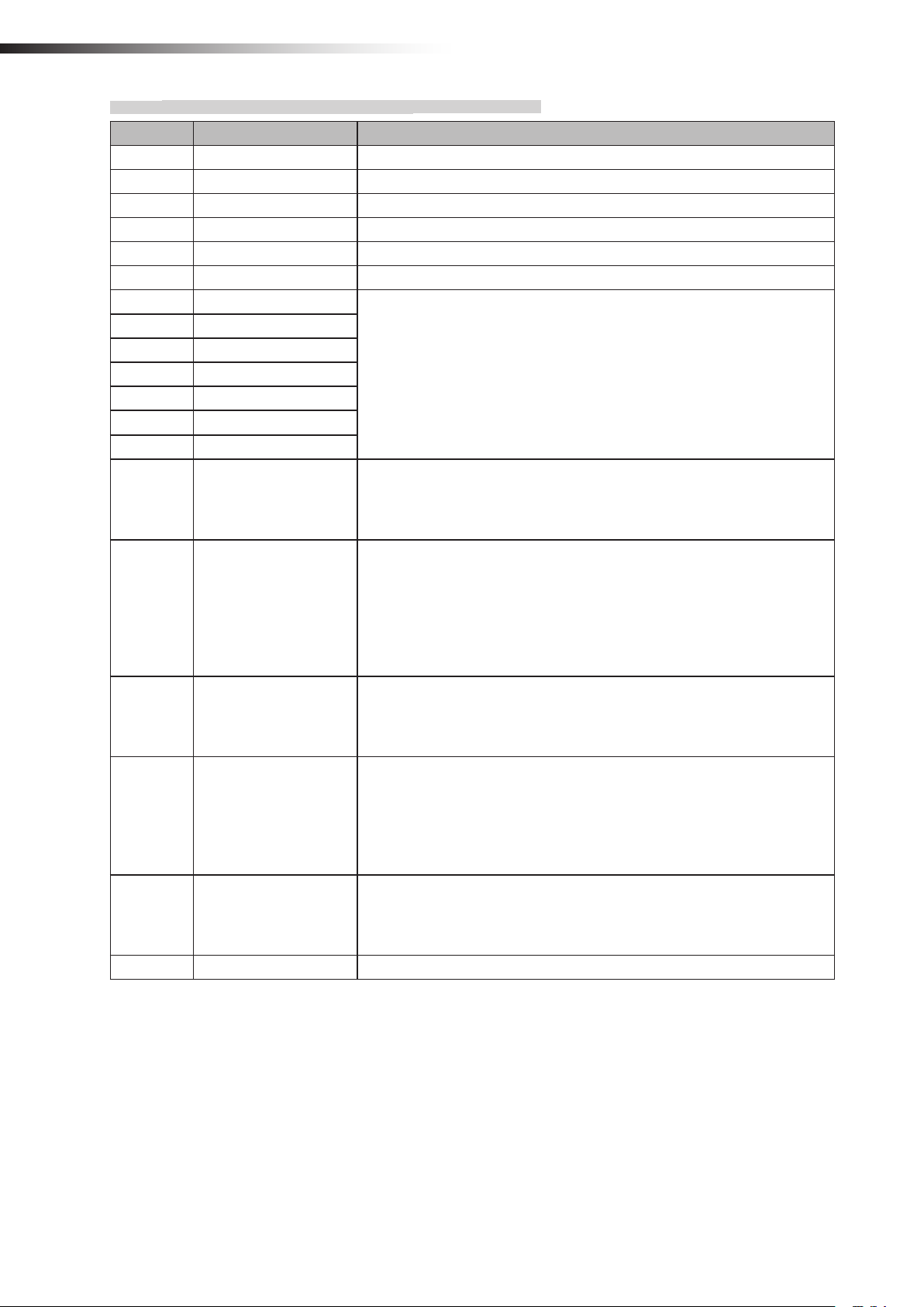
3 Frequency channel display
Frequency channel: 18
“Fxx” is displayed for 1 second.
xx: Frequency channel set value
Note: “F00” is displayed when the
PC setting is enabled.
- 19 -
ê 6. Part names and functions
2) Normal display
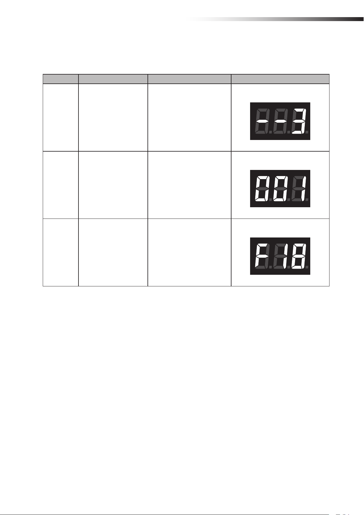
Contents Display Example
“ 0”
Standby
Intersection detection
Waiting for intersection
detection
Note: Displayed in the standby status.
“xxx” ↔ “ ”
Displayed for 0.5 second alternately.
xxx: Intersection address
Note: Displayed after the address magnetic plate
or ID tag has been recognized in the address
sensor mode or RFID mode.
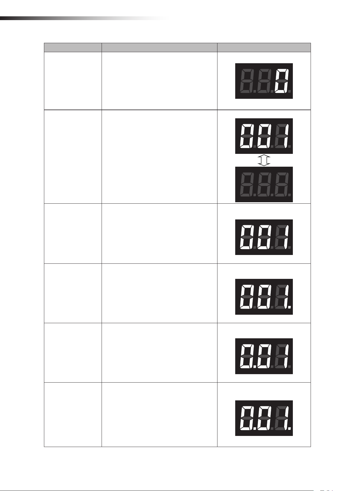
“xxx”
xxx: Intersection address
Note: Displayed while waiting after the intersection has been recognized.
Detection of intersection address 1
Intersection address 1
Passing through the
intersection
Waiting with the intersection top priority
Passing with the intersection top priority
“xxx.”
xxx: Intersection address
Note: Displayed when the intersection is recognized and the AGV is passing through the intersection.
“x.xx”
xxx: Intersection address
Note: Displayed when the intersection is recognized and the AGV is waiting with the intersection
top priority input turned ON.
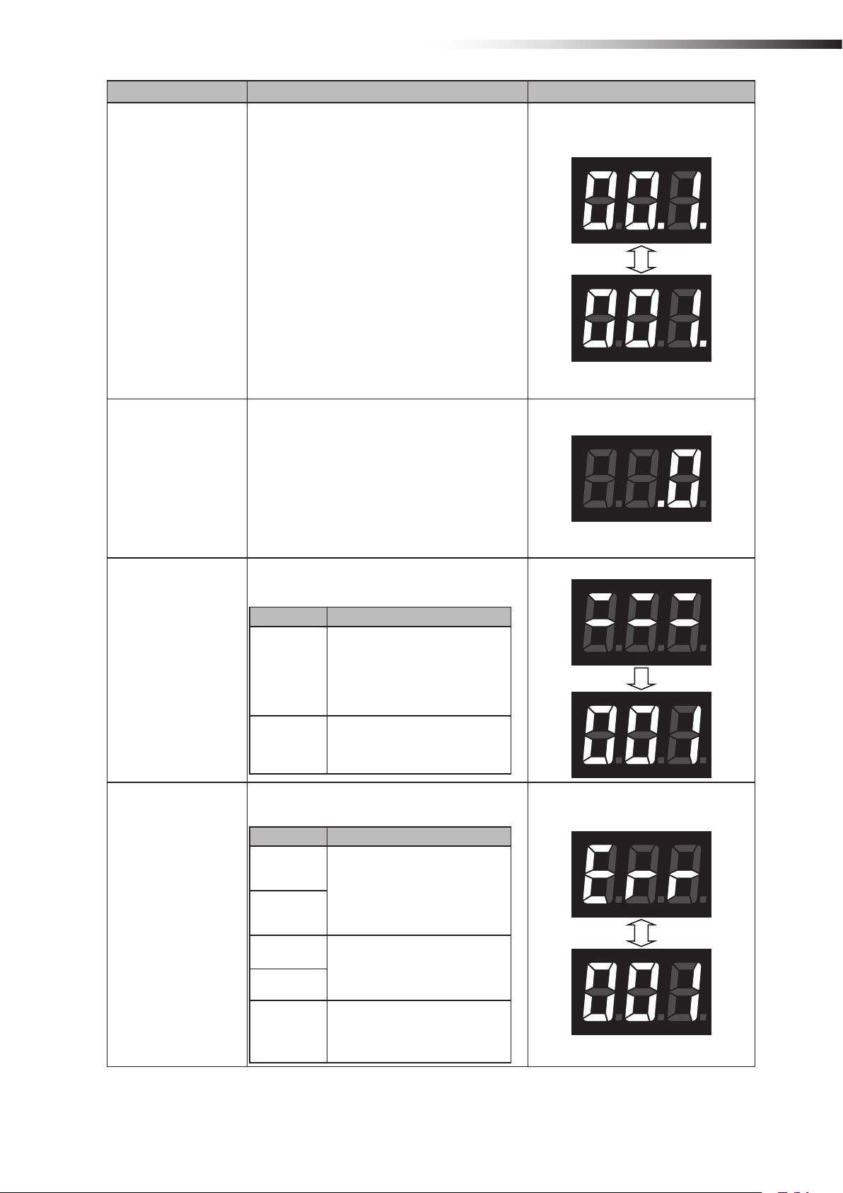
“x.xx.”
xxx: Intersection address
Note: Displayed when the intersection is recognized and the AGV is passing through the
intersection with the intersection top priority input
turned ON.
Intersection address 1
Intersection address 1
Intersection address 1
- 20 -
Contents Display Example
Intersection waiting
countup
“xx.x.” ↔ “xxx.”
The dot at the 2nd digit blinks.
xxx: Intersection address
Note: When the count for the communication
check from the wireless intersection module that
is passing through the intersection is incremented
in the waiting status, the status changes from
waiting to passing, and then it is displayed.
Note: When the count for the communication
check is incremented if there is no wireless
intersection module that is passing through the
intersection, the status changes to passing, and
then it is displayed.
Note: Displayed only when the intersection
control is performed by the wireless intersection
modules.
“ .0”
ê 6. Part names and functions
Intersection address 1
Ground station communication countup when
exiting intersection
Warning
Note: When the wireless intersection module that
was passing through the intersection exits the
intersection, this exit is transmitted to the ground
station. This display appears when the count for
the communication check is incremented.
Note: Displayed only when the intersection control is performed using the ground station.
“:::” Displayed for 1 second. → “xxx”
xxx: Warning code
Warning code Contents
The operation mode setting of the
wireless intersection module was not
001
100
registered to the parameters of the
ground station.
Register the parameters or change the
operation mode.
An internal reset occurred. Turn OFF
the power, and then turn it ON again.
“Err” and “xxx” are displayed alternately.
xxx: Error code
Error code Contents
Warning code: 001
Error code: 001
System error
001
002
100
101
102
The operation mode setting of the wireless intersection module might be out of
the setting range. Turn OFF all settings
of SW1, and then perform the settings
again.
Replace the wireless intersection
module.
The communication with the ground
station was not established.
- 21 -

ê 7. About related components
7.
7-1.
This box distributes the CN2 input/output cable wiring of the wireless intersection module FCU-RC01 in accordance
with the application.
A bracket to install the wireless intersection module on a ø28-Creform pipe is supplied with the box.
A power switch is provided. When using this box, turn the power switch ON.
Note that this product is dedicated for 24 V.
80
bout related components
A
Wireless intersection module box FCP-RCB01-24
CN2 connector for wireless intersection module
Unit: mm
171
(47)
30
CN1
CN2
CN3
CN4
7-1-1. CN1
Connector SMP-06V-NC cable to cable connection connector (JST)
Fitting connector SMR-06V-N cable to cable connection connector (JST)
Pin number Contents Address sensor mode RFID mode External control mode
1 +Vin - - 2 OUT1 Start Start Start
3 OUT6 Pause Pause 4 OUT2 Stop Stop Stop
5 IN10 AGV arrival AGV arrival AGV arrival
6 -Vin - - -
Power switch
CN1 connector for wireless
intersection module
- 22 -

7-1-2. CN2
Connector SMP-10V-NC cable to cable connection connector (JST)
Fitting connector SMR-10V-N cable to cable connection connector (JST)
Pin number Contents Address sensor mode RFID mode External control mode
1 IN9 Read timing - Intersection inquiry
2 IN1 Intersection address (1) - Intersection address (1)
3 IN2 Intersection address (2) - Intersection address (2)
4 IN3 Intersection address (4) - Intersection address (4)
5 IN4 Intersection address (8) - Intersection address (8)
6 IN5 Intersection address (16) - Intersection address (16)
7 IN6 Intersection address (32) - Intersection address (32)
8 IN7 Intersection address (64) - Intersection address (64)
9 +Vout - - -
10 -Vout - - -
ê 7. About related components
7-1-3. CN3
Connector SMP-05V-NC cable to cable connection connector (JST)
Fitting connector SMR-05V-N cable to cable connection connector (JST)
Pin number Contents Address sensor mode RFID mode External control mode
1 TxD - TxD 2 RxD - RxD 3 SGND - SGND 8 +Vout - - 9 -Vout - - -
7-1-4. CN4
Connector SMP-04V-NC cable to cable connection connector (JST)
Fitting connector SMR-04V-N cable to cable connection connector (JST)
Pin number Contents Address sensor mode RFID mode External control mode
1 IN8 AGV error AGV error AGV error
2 IN12 Battery voltage drop Battery voltage drop Battery voltage drop
3 IN13 Reset Reset Reset
4 -Vout - - -
- 23 -

ê 7. About related components
7-2.
Wireless intersection module box FCP-RCB01-12
The functions are the same as the FCP-RCB01-24.
A power switch is provided. When using this box, turn the power switch ON.
Note that this product is dedicated for 12V.
CN2 connector for wireless intersection module
2
1
8030
171
Unit: mm
Power switch
CN1 connector for wireless
intersection module
(47)
CN1
CN2
CN3
CN4
7-2-1. CN1
Connector SMP-06V-NC cable to cable connection connector (JST)
Fitting connector SMR-06V-N cable to cable connection connector (JST)
Pin number Contents Address sensor mode RFID mode External control mode
1 +Vin - - 2 OUT1 Start Start Start
3 OUT6 Pause Pause 4 OUT2 Stop Stop Stop
5 IN10 AGV arrival AGV arrival AGV arrival
6 -Vin - - -
- 24 -
7-2-2. CN2
Connector SMP-10V-NC cable to cable connection connector (JST)
Fitting connector SMR-10V-N cable to cable connection connector (JST)
Pin number Contents Address sensor mode RFID mode External control mode
1 IN9 Read timing - Intersection inquiry
2 IN1 Intersection address (1) - Intersection address (1)
3 IN2 Intersection address (2) - Intersection address (2)
4 IN3 Intersection address (4) - Intersection address (4)
5 IN4 Intersection address (8) - Intersection address (8)
6 IN5 Intersection address (16) - Intersection address (16)
7 IN6 Intersection address (32) - Intersection address (32)
8 IN7 Intersection address (64) - Intersection address (64)
9 +Vout - - -
10 -Vout - - -
ê 7. About related components
7-2-3. CN3
Connector SMP-05V-NC cable to cable connection connector (JST)
Fitting connector SMR-05V-N cable to cable connection connector (JST)
Pin number Contents Address sensor mode RFID mode External control mode
1 TxD - TxD 2 RxD - RxD 3 SGND - SGND 8 +Vout - - 9 -Vout - - -
7-2-4. CN4
Connector SMP-04V-NC cable to cable connection connector (JST)
Fitting connector SMR-04V-N cable to cable connection connector (JST)
Pin number Contents Address sensor mode RFID mode External control mode
1 IN8 AGV error AGV error AGV error
2 IN12 Battery voltage drop Battery voltage drop Battery voltage drop
3 IN13 Reset Reset Reset
4 -Vout - - -
- 25 -
ê 7. About related components
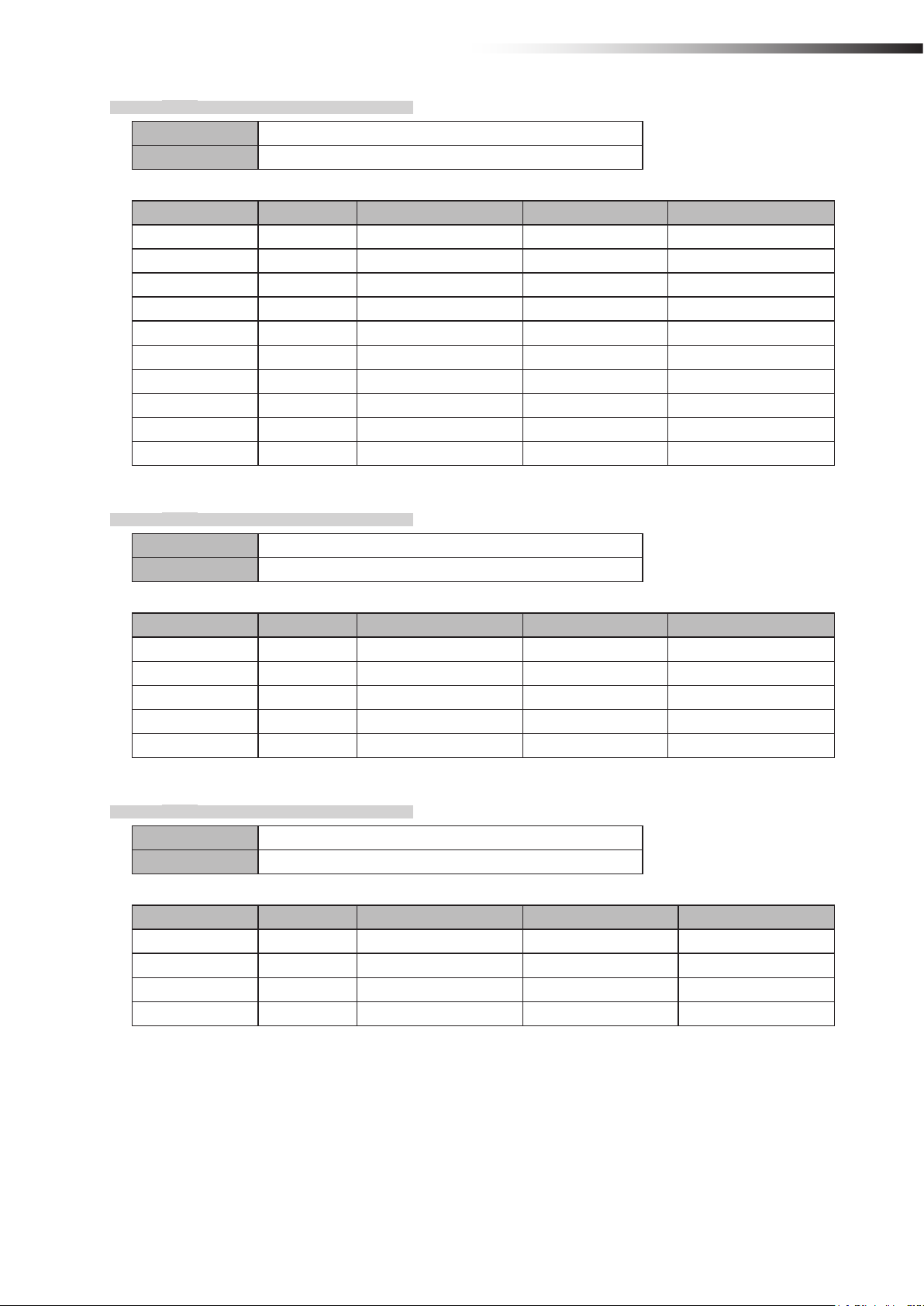
7-3.
This antenna is connected to the antenna connection section of the wireless intersection module FCU-RC01.
Pencil type antenna FCP-RCA01
6.4
89±3
10.2
SMA male pin
Unit: mm
Antenna List
No. Manufacturer Part No. Antenna Type Peak Gain
1 Arrow 7 ARN-AP03 Pencil type antenna 2.14dBi for 2.4 GHz
Note: The antenna connector is Reverse SMA type.
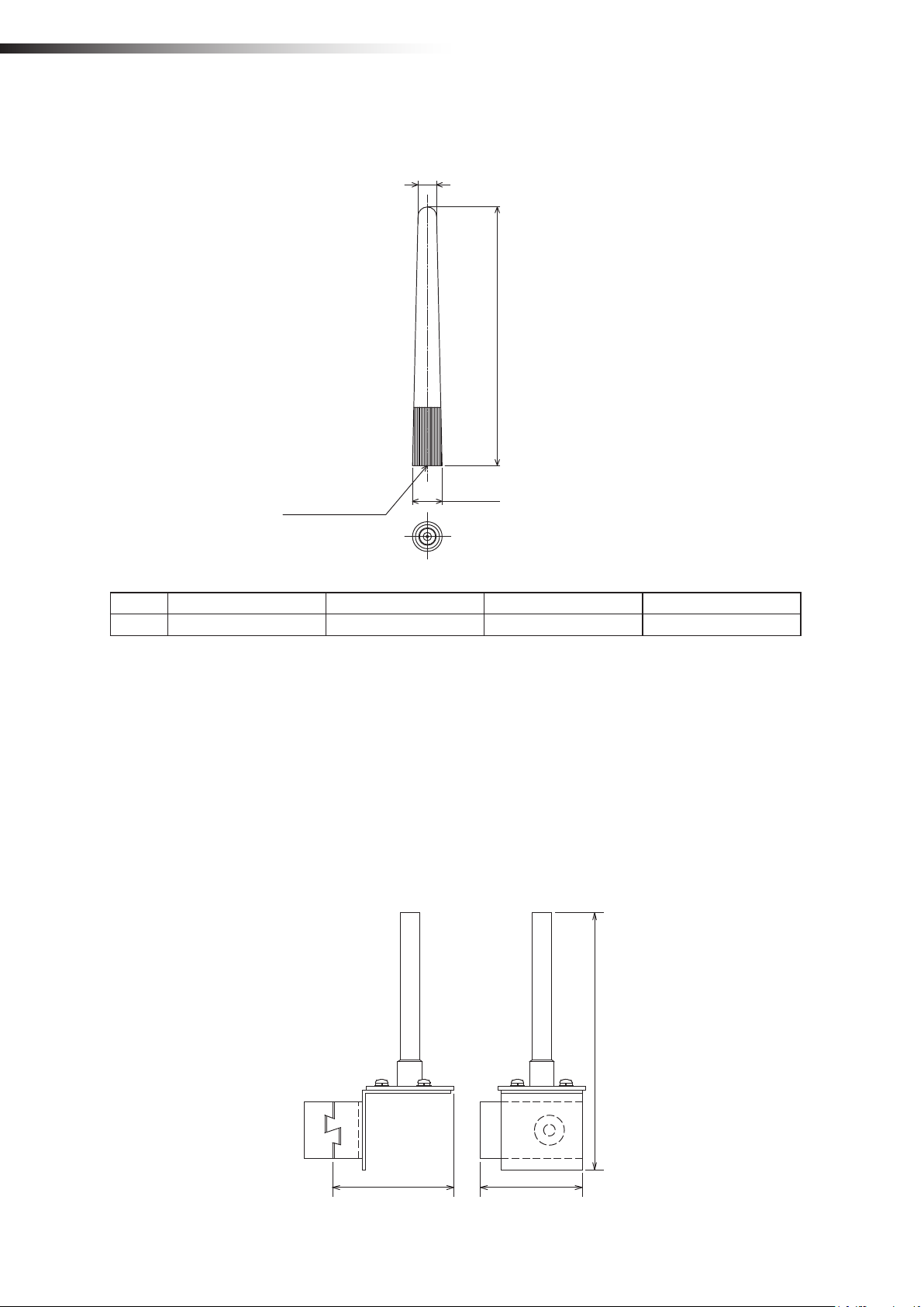
7-4.
This antenna is used when it is installed at a position away from the wireless intersection module.
• The cable length is approximately 1 m.
• The radio wave is attenuated (lost) by the cable.
• The communicable distance is shortened approximately 15% when compared to the pencil type antenna.
• When two wireless units that communicate with each other use the anged antennas, the communication distance
• For cable bending, the bending radius is 50 mm or more. If the cable is bent excessively, the insulator inside the
Flanged antenna with bracket FCP-RCA02
is shortened by approximately 30% due to double effects.
cable is deformed and the cable loss increases, causing the communicable distance to be shortened.
Unit: mm
69 (58)
- 26 -
146
ê 7. About related components
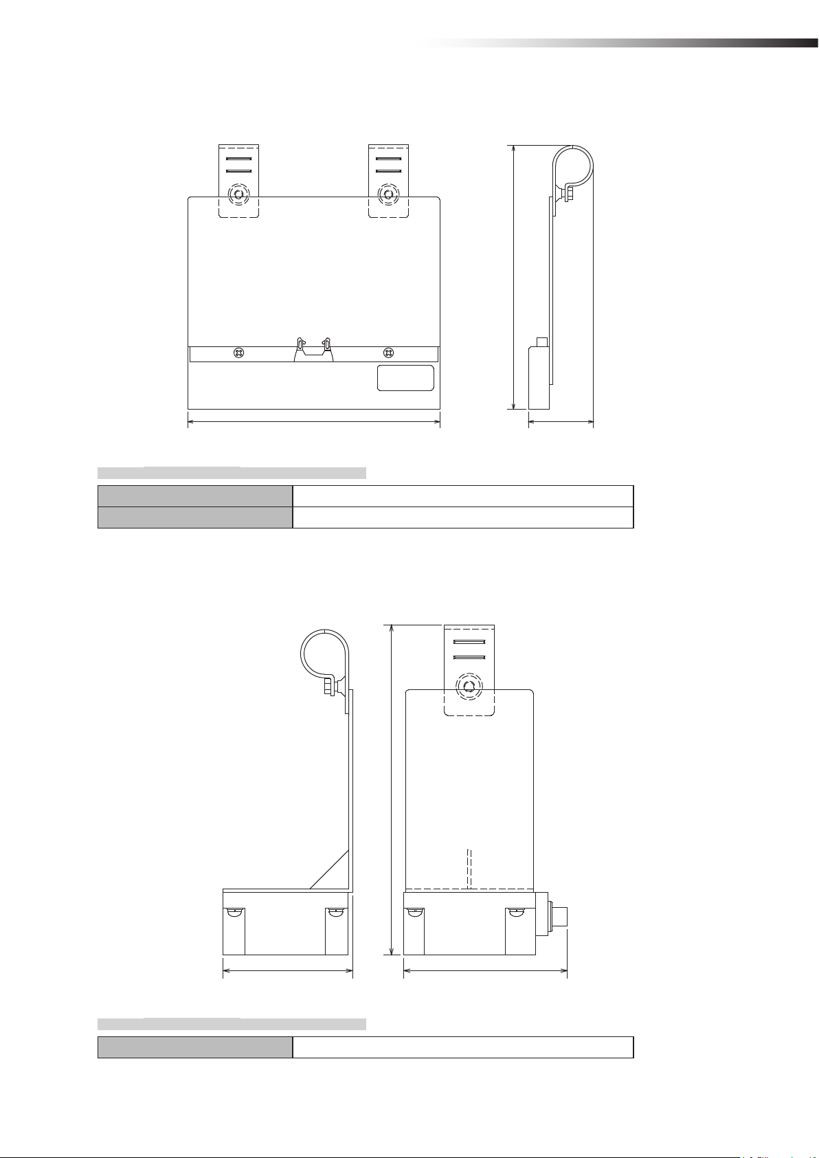
7-5.
This sensor reads the address magnetic plate to instruct the intersection entrance or intersection exit.
Address sensor with bracket FCP-RCS01
(212)
202 (52)
7-5-1. Specications
Unit: mm
Operating temperature range -10 to 60ºC (No dew condensation or freezing allowed.)
Operating humidity range 35 to 95% RH (No dew condensation allowed.)
7-6.
This sensor reads the ID tag to instruct the intersection entrance or intersection exit.
RFID antenna with bracket FCP-RCS02
(212)
Unit: mm
83 105
7-6-1. Specications
Operating temperature range 0 to 70ºC (No dew condensation or freezing allowed.)
- 27 -
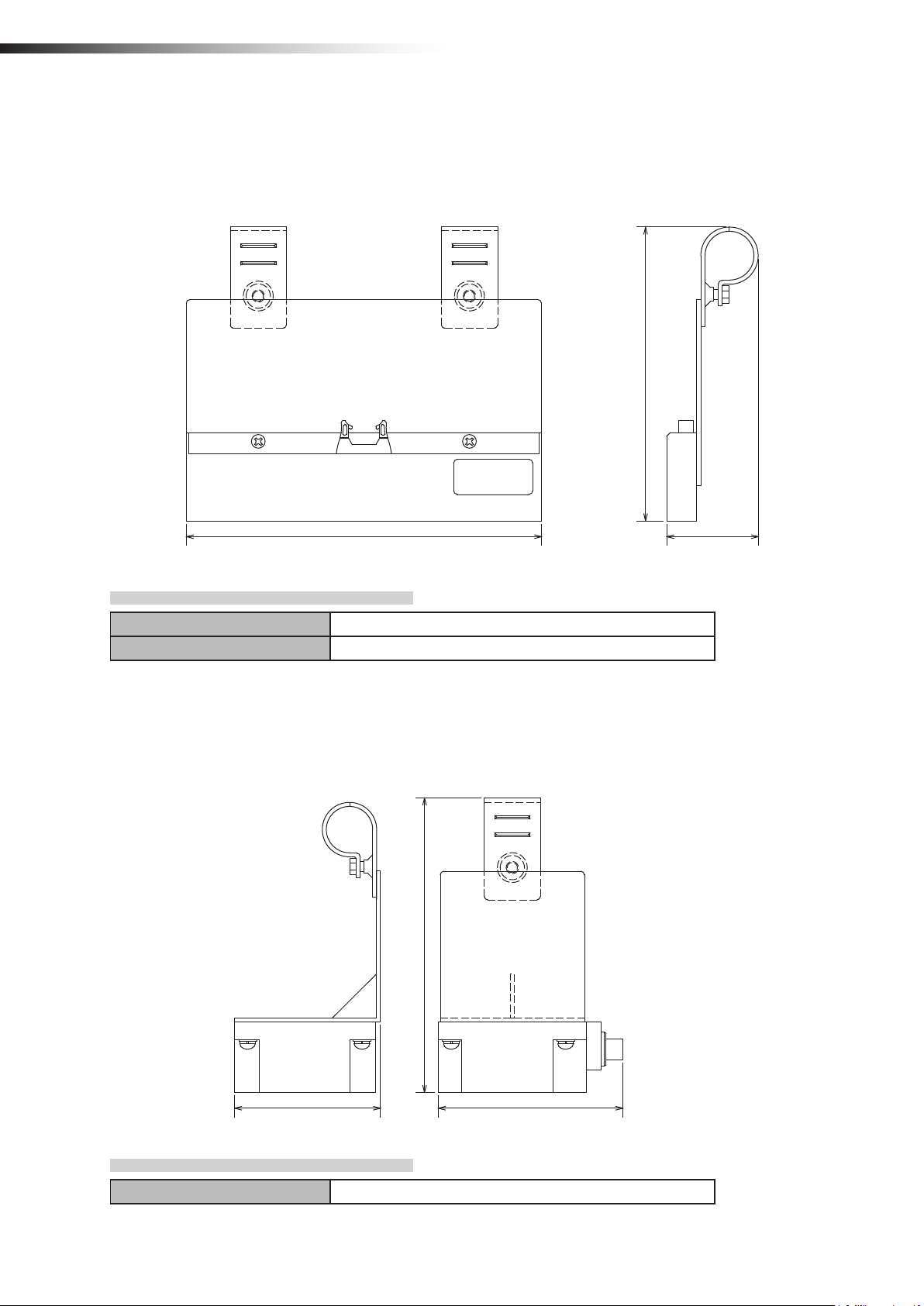
ê 7. About related components
7-7.
This sensor reads the address magnetic plate to instruct the intersection entrance or intersection exit.
This sensor is used for the small Drive Unit.
Address sensor with bracket for small Drive Unit FCP-RCS03
(168)
202
Unit: mm
(52)
7-7-1. Specications
Operating temperature range -10 to 60ºC (No dew condensation or freezing allowed.)
Operating humidity range 35 to 95% RH (No dew condensation allowed.)
7-8.
This sensor reads the ID tag to instruct the intersection entrance or intersection exit.
This sensor is used for the small Drive Unit.
RFID antenna with bracket for small Drive Unit FCP-RCS04
(168)
Unit: mm
83 105
7-8-1. Specications
Operating temperature range 0 to 70ºC (No dew condensation or freezing allowed.)
- 28 -
ê 7. About related components
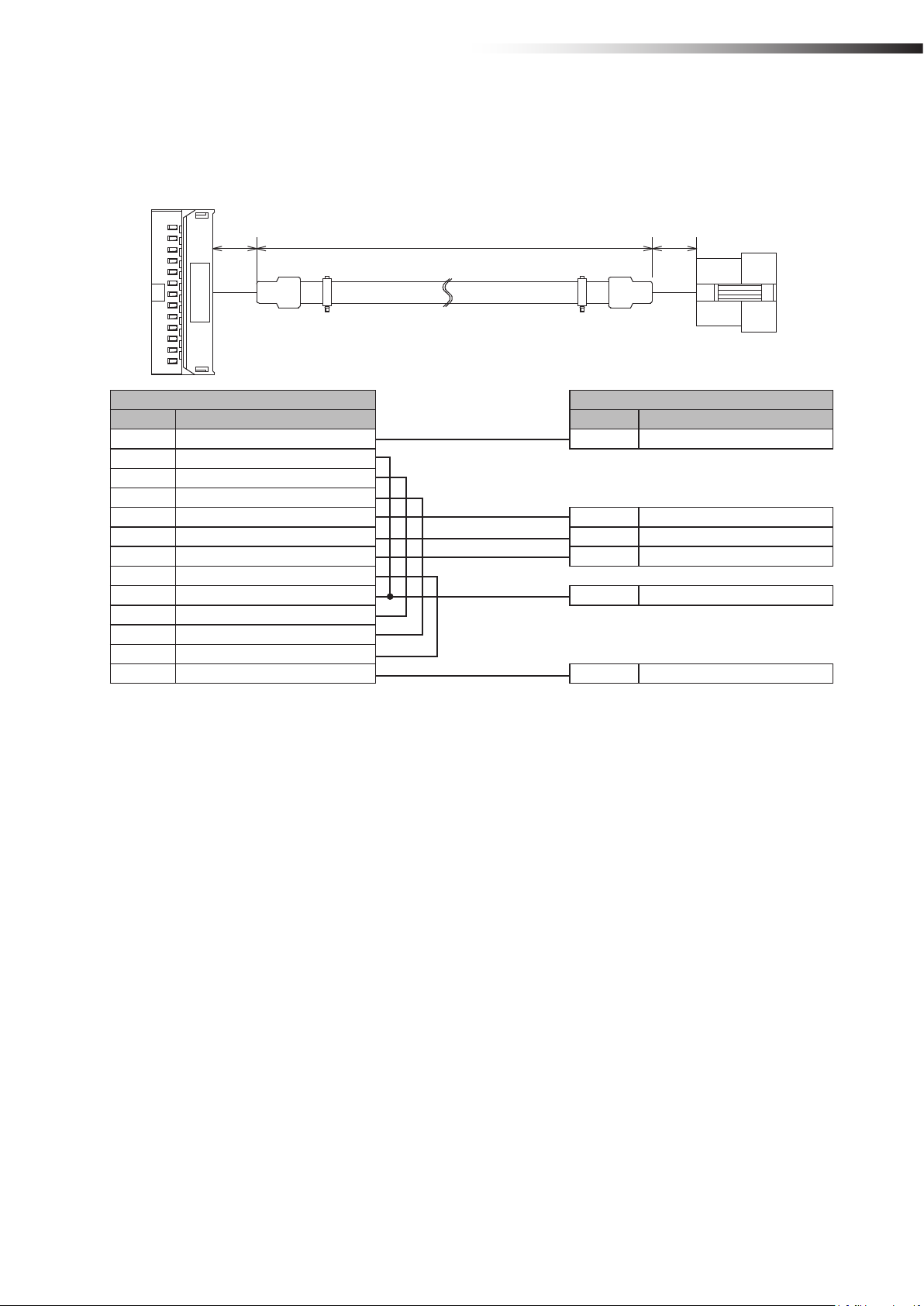
7-9.
Cable for 24 V Drive Unit FCP-RCC01-24
This cable connects the CNG connector of the 24 V forward Drive Unit and the CN1 connector of the wireless intersec-
tion module box.
Unit: mm
(30)
Drive Unit CNG connector CN1 connector of wireless intersection module box
Pin number Contents Pin number Contents
1 +24 V 1 +Vin
5 Command stop input
Right travel/medium speed change-over input
6
7
Speed change-over/medium speed change-over input
8 Start signal input 2 Start input
10 Pause input 3 Pause output
11 Stop input 4 Stop output
12 Input change-over input
13 S sensor output 5 AGV arrival input
Right travel/medium speed change-over output
14
15
Speed change-over/medium speed change-over output
21 0 V
22 0 V 6 -Vin
(1500)
(30)
- 29 -
ê 7. About related components
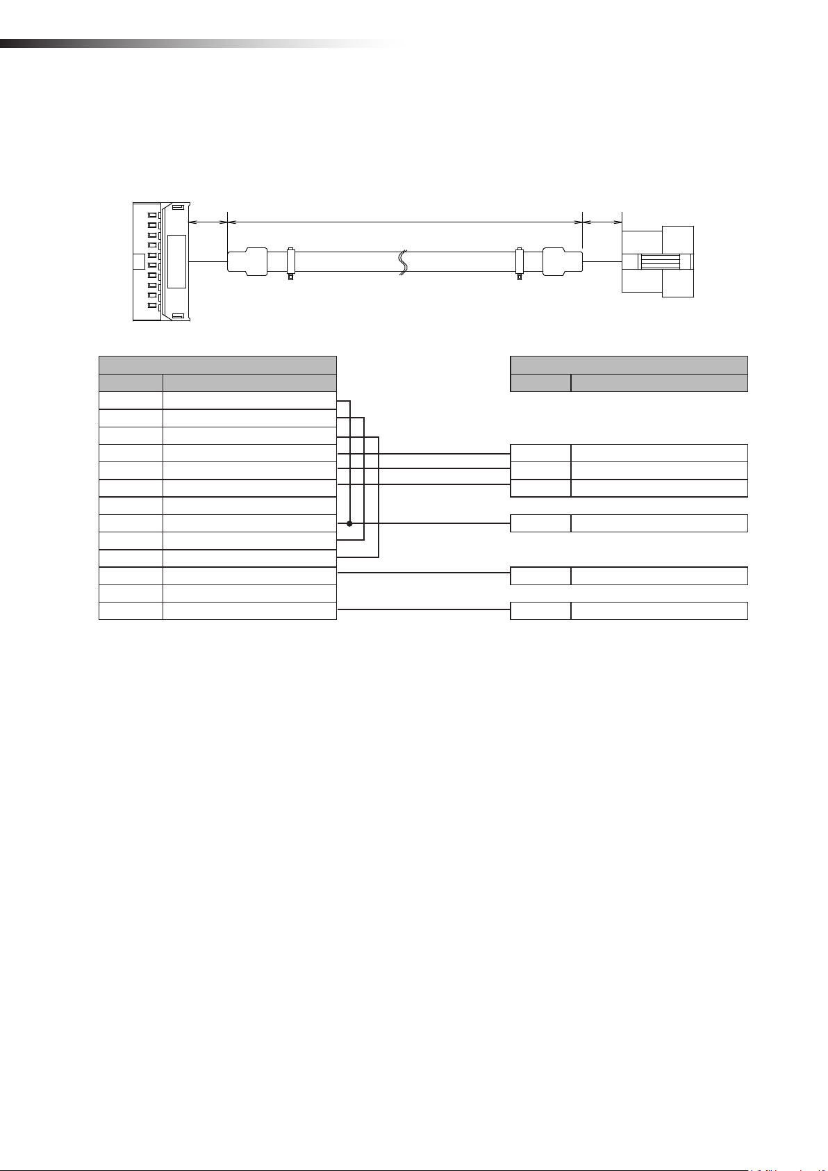
7-10.
Cable for 12V Drive Unit FCP-RCC01-12
This cable connects the CNG connector of the 12V forward Drive Unit and the CN1 connector of the wireless intersec-
tion module box.
Unit: mm
(1500) (30)(30)
Drive Unit CNG connector CN1 connector of wireless intersection module box
Pin number Contents Pin number Contents
1 Command stop input
2
Right travel/medium speed change-over input
3
Speed change-over/medium speed change-over input
4 Start signal input 2 Start output
6 Pause input 3 Pause output
7 Stop input 4 Stop output
8 Input change-over input
9 S sensor output 5 AGV arrival input
Right travel/medium speed change-over output
10
11
Speed change-over/medium speed change-over output
17 +12 V 1 +Vin
19 0 V
20 0 V 6 -Vin
- 30 -
 Loading...