

Page 1

AC Servo Drives
Σ-II Series
SGM
/SGDM
USER'S MANUAL
SGMAH/SGMPH/SGMGH/SGMSH/SGMDH/SGMCS Servomotors
SGDM SERVOPACK
Outline
1
MODE/SET
YASKAWA
SERVOPACK
SGDM-
CHARGE POWER
L1C
L2C
200V
DATA/
L1
C
N
L2
3
+ 1
+ 2
C
N
1
B1
B2
U
V
C
W
N
MANUAL NO. SIEP S800000 15D
Selections
Servomotor Specifications and
Dimensional Drawings
SERVOPACK Specifications and
Dimensional Drawings
Specifications and Dimensional Drawings of
Cables and Peripheral Devices
Wiring
Digital Operator/Panel Operator
Operation
Adjustments
Upgraded Versions
Inspection, Maintenance,
and Troubleshooting
Appendix
2
3
4
5
6
7
8
9
10
11
12
Page 2

Copyright © 2003 YASKAWA ELECTRIC CORPORATION
All rights reserved. No part of this publication may be reproduced, stored in a retrieval system,
or transmitted, in any form, or by any means, mechanical, electronic, photocopying, recording,
or otherwise, without the prior written permission of Yaskawa. No patent liability is assumed
with respect to the use of the information contained herein. Moreover, because Yaskawa is constantly striving to improve its high-quality products, the information contained in this manual is
subject to change without notice. Every precaution has been taken in the preparation of this
manual. Nevertheless, Yaskawa assumes no responsibility for errors or omissions. Neither is
any liability assumed for damages resulting from the use of the information contained in this
publication.
Page 3

About this Manual
Intended Audience
This manual is intended for the following users.
•
Those selecting Σ-II Series servo drives or peripheral devices for Σ-II Series servo drives.
•
Those wanting to know about the ratings and characteristics of Σ-II Series servo drives.
•
•
•
•
Description of Technical Terms
The terms in this manual are defined as follows:
• Servomotor or motor = Σ-II Series SGMAH, SGMPH, SGMGH, SGMSH, SGMDH, SGMCS servomo-
• SERVOPACK = Σ-II Series SGDM amplifier.
• Servo drive = A set including a servomotor and servo amplifier.
• Servo System = A servo control system that includes the combination of a servo drive with a host
• Parameter number = Numbers that the user inputs toward the SERVOPACK.
Indication of Reverse Signals
In this manual, the names of reverse signals (ones that are valid when low) are written with a forward slash (/)
before the signal name, as shown in the following example:
• S-ON
designing Σ-II Series servo drive systems.
Those
Those installing or wiring Σ-II Series servo drives.
Those performing trial operation or adjustments of Σ-II Series servo drives.
Those maintaining or inspecting Σ-II Series servo drives.
tor.
computer and peripheral devices.
/S-ON
=
• P-CON
=
/P-CON
iii
Page 4

IMPORTANT
INFO
EXAMPLE
TERMS
Quick access to your required information
Read the chapters marked with 9 to get the information required for your purpose.
Chapter
Chapter 1
Outline
Chapter 2
Selections
Chapter 3
Servomotor Specifications
and Dimensional Drawings
Chapter 4
SERVOPACK Specifications
and Dimensional Drawings
Chapter 5
Specifications and
Dimensional Drawings of
Cables and Peripheral
Devices
Chapter 6
Wiring
Chapter 7
Digital Operator/Panel
Operator
Chapter 8
Operation
Chapter 9
Adjustments
Chapter 10
Upgraded Versions
Chapter 11
Inspection, Maintenance,
and Troubleshooting
Chapter 12
Appendix
SERVOPACKs,
Servomotors,
and Peripheral
Devices
Ratings and
Character-
istics
System
Design
Panel
Configura-tion
and Wiring
Trial Operation
and Servo
Adjustment
Inspection and
Maintenance
9
9
9999
9999
9999
99 9
99
9
9
9999
9
9999
iv
Visual Aids
■
The following aids are used to indicate certain types of information for easier reference.
• Indicates important information that should be memorized, including precautions such as alarm displays to avoid damaging the devices.
• Indicates supplemental information.
• Indicates application examples.
• Indicates definitions of difficult terms or terms that have not been previously explained in this manual.
Page 5

Related Manuals
Refer to the following manuals as required.
Manual Name Manual Number Contents
-II Series SGMH/SGDM
Σ
Digital Operator Operation Manual
Series/Σ-II Series SERVOPACKs
Σ
Personal Computer Monitoring Software
Operation Manual
TOE-S800-34 Provides detailed information on the operating method
SIE-S800-35 Describes the using and the operating methods on soft-
of JUSP-OP02A-2 type Digital Operator (option
device).
ware that changes the local personal computer into the
monitor equipment for the Σ-II Series servomotor.
v
Page 6
WARNING
CAUTION
PROHIBITED
MANDATORY
Safety Information
The following conventions are used to indicate precautions in this manual. Failure to heed precautions provided
in this manual can result in serious or possibly even fatal injury or damage to the products or to related equipment
and systems.
Indicates precautions that, if not heeded, could possibly result in loss of life or serious
injury.
Indicates precautions that, if not heeded, could result in relatively serious or minor
injury, damage to the product, or faulty operation.
In some situations, the precautions indicated could have serious consequences if not heeded.
Indicates prohibited actions that must not be performed. For example, this symbol
would be used as follows to indicate that fire is prohibited: .
Indicates compulsory actions that must be performed. For example, this symbol would
be used as follows to indicate that grounding is compulsory: .
vi
Page 7

Notes for Safe Operation
WARNING
Read this manual thoroughly before checking products on delivery, storage and transportation, installation,
wiring, operation and inspection, and disposal of the AC servo drive.
• Never touch any rotating motor parts while the motor is running.
Failure to observe this warning may result in injury.
• Before starting operation with a machine connected, make sure that an emergency stop can
be applied at any time.
Failure to observe this warning may result in injury.
• Never touch the inside of the SERVOPACKs.
Failure to observe this warning may result in electric shock.
• Do not touch terminals for five minutes after the power is turned OFF.
Residual voltage may cause electric shock.
• Do not touch terminals for five minutes after voltage resistance test.
Residual voltage may cause electric shock.
• Follow the procedures and instructions for trial operation precisely as described in this manual.
Malfunctions that occur after the servomotor is connected to the equipment not only damage the
equipment, but may also cause an accident resulting in death or injury.
• The multiturn limit value must be changed only for special applications.
Changing it inappropriately or unintentionally can be dangerous.
• If the Multiturn Limit Disagreement alarm (A.CC) occurs, check the setting of parameter
Pn205 in the SERVOPACK to be sure that it is correct.
If Fn013 is executed when an incorrect value is set in Pn205, an incorrect value will be set in the
encoder. The alarm will disappear even if an incorrect value is set, but incorrect positions will be
detected, resulting in a dangerous situation where the machine will move to unexpected positions.
• Do not remove the front cover, cables, connectors, or optional items while the power is ON.
Failure to observe this warning may result in electric shock.
• Installation, disassembly, or repair must be performed only by authorized personnel.
Failure to observe this warning may result in electric shock or injury.
• Do not damage, press, exert excessive force or place heavy objects on the cables.
Failure to observe this warning may result in electric shock, stopping operation of the product, or
burning.
• Provide an appropriate stopping device on the machine side to ensure safety.
A holding brake for a servomotor with brake is not a stopping device for ensuring safety.
Failure to observe this warning may result in injury.
• Do not come close to the machine immediately after resetting momentary power loss to
avoid an unexpected restart.
Take appropriate measures to ensure safety against an unexpected restart.
Failure to observe this warning may result in injury.
• Do not modify the product.
Failure to observe this warning may result in injury or damage to the product.
• Connect the ground terminal to electrical codes (ground resistance: 100
Improper grounding may result in electric shock or fire.
or less).
Ω
vii
Page 8

CAUTION
CAUTION
Checking on Delivery
• Always use the servomotor and SERVOPACK in one of the specified combinations.
Failure to observe this caution may result in fire or malfunction.
Storage and Transportation
• Do not store or install the product in the following places.
• Locations subject to direct sunlight.
• Locations subject to temperatures outside the range specified in the storage or installation temperature
conditions.
• Locations subject to humidity outside the range specified in the storage or installation humidity
conditions.
• Locations subject to condensation as the result of extreme changes in temperature.
• Locations subject to corrosive or flammable gases.
• Locations subject to dust, salts, or iron dust.
• Locations subject to exposure to water, oil, or chemicals.
• Locations subject to shock or vibration.
Failure to observe this caution may result in fire, electric shock, or damage to the product.
• Do not hold the product by the cables or motor shaft while transporting it.
Failure to observe this caution may result in injury or malfunction.
• Do not place any load exceeding the limit specified on the packing box.
Failure to observe this caution may result in injury or malfunction.
• If disinfectants or insecticides must be used to treat packing materials such as wooden frames,
pallets, or plywood, the packing materials must be treated before the product is packaged, and
methods other than fumigation must be used.
Example: Heat treatment, where materials are kiln-dried to a core temperature of 56°C for 30
minutes or more.
If the electronic products, which include stand-alone products and products installed in machines, are
packed with fumigated wooden materials, the electrical components may be greatly damaged by the
gases or fumes resulting from the fumigation process. In particular, disinfectants containing halogen,
which includes chlorine, fluorine, bromine, or iodine can contribute to the erosion of the capacitors.
viii
Page 9

Installation
CAUTION
CAUTION
• Never use the products in an environment subject to water, corrosive gases, inflammable gases, or
combustibles.
Failure to observe this caution may result in electric shock or fire.
• Do not step on or place a heavy object on the product.
Failure to observe this caution may result in injury.
• Do not cover the inlet or outlet parts and prevent any foreign objects from entering the product.
Failure to observe this caution may cause internal elements to deteriorate resulting in malfunction or fire.
• Be sure to install the product in the correct direction.
Failure to observe this caution may result in malfunction.
• Provide the specified clearances between the SERVOPACK and the control panel or with other devices.
Failure to observe this caution may result in fire or malfunction.
• Do not apply any strong impact.
Failure to observe this caution may result in malfunction.
Wiring
• Do not connect a three-phase power supply to the U, V, or W output terminals.
Failure to observe this caution may result in injury or fire.
• Securely connect the power supply terminals and motor output terminals.
Failure to observe this caution may result in fire.
• Do not apply stress to connectors.
• Do not bundle or run power and signal lines together in the same duct. Keep power and signal lines
separated by at least 30 cm.
Failure to observe this caution may result in malfunction.
• Use twisted-pair shielded wires or multi-core twisted pair shielded wires for signal and encoder (PG)
feedback lines.
The maximum length is 3 m for reference input lines and is 20 m for PG feedback lines.
• Do not touch the power terminals for five minutes after turning power OFF because high voltage may still
remain in the SERVOPACK.
Make sure the charge indicator is turned OFF first before starting an inspection.
• Avoid frequently turning power ON and OFF. Do not turn power ON or OFF more than once per minute.
Since the SERVOPACK has a capacitor in the power supply, a high charging current flows for 0.2 seconds when
power is turned ON. Frequently turning power ON and OFF causes main power devices such as capacitors and fuses
to deteriorate, resulting in unexpected problems.
• Observe the following precautions when wiring main circuit terminal blocks.
• Remove the terminal block from the SERVOPACK prior to wiring.
• Insert only one wire per terminal on the terminal block.
• Make sure that the core wire is not electrically shorted to adjacent core wires.
• Do not connect the SERVOPACK for 100 V and 200 V directly to a voltage of 400 V.
The SERVOPACK will be destroyed.
ix
Page 10

CAUTION
• Install the battery at either the host controller or the SERVOPACK of the encoder.
It is dangerous to install batteries at both simultaneously, because that sets up a loop circuit between the batteries.
• Be sure to wire correctly and securely.
Failure to observe this caution may result in motor overrun, injury, or malfunction.
• Always use the specified power supply voltage.
An incorrect voltage may result in burning.
• Take appropriate measures to ensure that the input power supply is supplied within the specified voltage
fluctuation range. Be particularly careful in places where the power supply is unstable.
An incorrect power supply may result in damage to the product.
• Connect the brake power supply properly, keeping in mind the difference of 90-V and 24-V power supplies.
• Install external breakers or other safety devices against short-circuiting in external wiring.
Failure to observe this caution may result in fire.
• Do not modify connectors.
• Take appropriate and sufficient countermeasures for each when installing systems in the following
locations.
• Locations subject to static electricity or other forms of noise.
• Locations subject to strong electromagnetic fields and magnetic fields.
• Locations subject to possible exposure to radioactivity.
• Locations close to power supplies including power supply lines.
Failure to observe this caution may result in damage to the product.
• Do not reverse the polarity of the battery when connecting it.
Failure to observe this caution may damage the battery or cause it to explode.
x
Page 11
Operation
CAUTION
CAUTION
• Conduct trial operation on the servomotor alone with the motor shaft disconnected from machine to avoid
any unexpected accidents.
Failure to observe this caution may result in injury.
• Before starting operation with a machine connected, change the settings to match the parameters of the
machine.
Starting operation without matching the proper settings may cause the machine to run out of control or malfunction.
• Forward run prohibited (P-OT) and reverse run prohibited (N-OT) signals are not effective during zero point
search mode using parameter Fn003.
• When using the servomotor for a vertical axis, install the safety devices to prevent workpieces to fall off due
to occurrence of alarm or overtravel. Set the servomotor so that it will stop in the zero clamp state at
occurrence of overtravel.
Failure to observe this caution may cause workpieces to fall off due to overtravel.
• When not using the normal autotuning, set to the correct moment of inertia ratio.
Setting to an incorrect moment of inertia ratio may cause vibration.
• Do not touch the SERVOPACK heatsinks, regenerative resistor, or servomotor while power is ON or soon
after the power is turned OFF.
Failure to observe this caution may result in burns due to high temperatures.
• Do not make any extreme adjustments or setting changes of parameters.
Failure to observe this caution may result in injury due to unstable operation.
• When an alarm occurs, remove the cause, reset the alarm after confirming safety, and then resume
operation.
Failure to observe this caution may result in injury.
• Do not use the servo brake of the servomotor for ordinary braking.
Failure to observe this caution may result in malfunction.
• Do not turn the Servo ON or OFF unless necessary.
Failure to observe this caution may cause internal parts to deteriorate.
Maintenance and Inspection
• When replacing the SERVOPACK, transfer the previous SERVOPACK parameters to the new
SERVOPACK before resuming operation.
Failure to observe this caution may result in damage to the product.
• Do not attempt to change wiring while the power is ON.
Failure to observe this caution may result in electric shock or injury.
•
Do not disassemble the servomotor.
Failure to observe this caution may result in electric shock or injury.
xi
Page 12

CAUTION
Disposal
• When disposing of the products, treat them as ordinary industrial waste.
General Precautions
Note the following to ensure safe application.
• The drawings presented in this manual are sometimes shown without covers or protective guards. Always replace
the cover or protective guard as specified first, and then operate the products in accordance with the manual.
• The drawings presented in this manual are typical examples and may not match the product you received.
• This manual is subject to change due to product improvement, specification modification, and manual
improvement. When this manual is revised, the manual code is updated and the new manual is published as a next
edition.
• If the manual must be ordered due to loss or damage, inform your nearest Yaskawa representative or one of the
offices listed on the back of this manual.
• Yaskawa will not take responsibility for the results of unauthorized modifications of this product. Yaskawa shall
not be liable for any damages or troubles resulting from unauthorized modification.
xii
Page 13

CONTENTS
About this Manual - - - - - - - - - - - - - - - - - - - - - - - - - - - - - - - - - - - - - - - - - - - - - - - - - - - - - - - -iii
Related Manuals - - - - - - - - - - - - - - - - - - - - - - - - - - - - - - - - - - - - - - - - - - - - - - - - - - - - - - - - -v
Safety Information - - - - - - - - - - - - - - - - - - - - - - - - - - - - - - - - - - - - - - - - - - - - - - - - - - - - - - - vi
Notes for Safe Operation - - - - - - - - - - - - - - - - - - - - - - - - - - - - - - - - - - - - - - - - - - - - - - - - - - vii
1 Outline
1.1 Checking Products - - - - - - - - - - - - - - - - - - - - - - - - - - - - - - - - - - - - - - - - - - - - 1-2
1.1.1 Check Items - - - - - - - - - - - - - - - - - - - - - - - - - - - - - - - - - - - - - - - - - - - - - - - - - - - - - - - - - - 1-2
1.1.2 Servomotors - - - - - - - - - - - - - - - - - - - - - - - - - - - - - - - - - - - - - - - - - - - - - - - - - - - - - - - - - - 1-2
1.1.3 SERVOPACKs - - - - - - - - - - - - - - - - - - - - - - - - - - - - - - - - - - - - - - - - - - - - - - - - - - - - - - - - 1-3
1.2 Product Part Names - - - - - - - - - - - - - - - - - - - - - - - - - - - - - - - - - - - - - - - - - - - 1-4
1.2.1 Servomotors - - - - - - - - - - - - - - - - - - - - - - - - - - - - - - - - - - - - - - - - - - - - - - - - - - - - - - - - - - 1-4
1.2.2 SERVOPACKs - - - - - - - - - - - - - - - - - - - - - - - - - - - - - - - - - - - - - - - - - - - - - - - - - - - - - - - - 1-6
1.3 Examples of Servo System Configurations - - - - - - - - - - - - - - - - - - - - - - - - - - - 1-8
1.3.1 Single-phase, 100 V and 200 V Main Circuit - - - - - - - - - - - - - - - - - - - - - - - - - - - - - - - - - - - 1-8
1.3.2 Three-phase, 200 V Main Circuit- - - - - - - - - - - - - - - - - - - - - - - - - - - - - - - - - - - - - - - - - - - - 1-9
1.3.3 Connecting to SGMCS Servomotor- - - - - - - - - - - - - - - - - - - - - - - - - - - - - - - - - - - - - - - - - 1-10
1.4 Applicable Standards - - - - - - - - - - - - - - - - - - - - - - - - - - - - - - - - - - - - - - - - - 1-11
1.4.1 North American Safety Standards (UL, CSA) - - - - - - - - - - - - - - - - - - - - - - - - - - - - - - - - - - 1-11
1.4.2 CE Marking- - - - - - - - - - - - - - - - - - - - - - - - - - - - - - - - - - - - - - - - - - - - - - - - - - - - - - - - - - 1-11
1.5 Σ-II Series SGDM SERVOPACK Upgraded Functions - - - - - - - - - - - - - - - - - - 1-12
2 Selections
2.1 Servomotor Model Designations - - - - - - - - - - - - - - - - - - - - - - - - - - - - - - - - - - 2-2
2.1.1 Model SGMAH (3000 min-1) - - - - - - - - - - - - - - - - - - - - - - - - - - - - - - - - - - - - - - - - - - - - - - - 2-2
2.1.2 Model SGMPH (3000 min
2.1.3 Model SGMGH (1500 min
2.1.4 Model SGMGH (1000 min
2.1.5 Model SGMSH (3000 min
2.1.6 Model SGMDH (2000 min
2.1.7 Model SGMCS - - - - - - - - - - - - - - - - - - - - - - - - - - - - - - - - - - - - - - - - - - - - - - - - - - - - - - - 2-13
2.2 SERVOPACK Model Designations - - - - - - - - - - - - - - - - - - - - - - - - - - - - - - - - 2-14
2.3 Σ-II Series SERVOPACKs and Applicable Servomotors - - - - - - - - - - - - - - - - - 2-15
2.3.1 SGDM SERVOPACKs and SGMH Servomotors - - - - - - - - - - - - - - - - - - - - - - - - - - - - - - 2-15
2.3.2 SGDM SERVOPACKs and SGMCS Servomotors- - - - - - - - - - - - - - - - - - - - - - - - - - - - - - - 2-16
-1
) - - - - - - - - - - - - - - - - - - - - - - - - - - - - - - - - - - - - - - - - - - - - - - - 2-4
-1
)- - - - - - - - - - - - - - - - - - - - - - - - - - - - - - - - - - - - - - - - - - - - - - - 2-6
-1
)- - - - - - - - - - - - - - - - - - - - - - - - - - - - - - - - - - - - - - - - - - - - - - - 2-8
-1
) - - - - - - - - - - - - - - - - - - - - - - - - - - - - - - - - - - - - - - - - - - - - - - 2-10
-1
)- - - - - - - - - - - - - - - - - - - - - - - - - - - - - - - - - - - - - - - - - - - - - - 2-12
2.4 Selecting Cables - - - - - - - - - - - - - - - - - - - - - - - - - - - - - - - - - - - - - - - - - - - - 2-17
2.4.1 Cables for SGMAH and SGMPH Servomotors - - - - - - - - - - - - - - - - - - - - - - - - - - - - - - - - - 2-17
2.4.2 Cables for SGMGH/SGMSH/SGMDH Servomotors - - - - - - - - - - - - - - - - - - - - - - - - - - - - - 2-20
2.4.3 Cables for SGMCS Servomotors - - - - - - - - - - - - - - - - - - - - - - - - - - - - - - - - - - - - - - - - - - 2-23
2.5 Selecting Peripheral Devices - - - - - - - - - - - - - - - - - - - - - - - - - - - - - - - - - - - - 2-26
xiii
Page 14

2.5.1 Special Options - - - - - - - - - - - - - - - - - - - - - - - - - - - - - - - - - - - - - - - - - - - - - - - - - - - - - - -2-26
2.5.2 Molded-case Circuit Breaker and Fuse Capacity - - - - - - - - - - - - - - - - - - - - - - - - - - - - - - - -2-28
2.5.3 Noise Filters, Magnetic Conductors, Surge Absorbers and DC Reactors - - - - - - - - - - - - - - - 2-29
2.5.4 Regenerative Resistors and Brake Power Supply Units - - - - - - - - - - - - - - - - - - - - - - - - - - -2-30
3 Servomotor Specifications and Dimensional Drawings
3.1 Ratings and Specifications of SGMAH (3000 min-1) - - - - - - - - - - - - - - - - - - - - - 3-4
3.1.1 SGMAH Servomotors Without Gears - - - - - - - - - - - - - - - - - - - - - - - - - - - - - - - - - - - - - - - - -3-4
3.1.2 SGMAH Servomotors With Standard Backlash Gears - - - - - - - - - - - - - - - - - - - - - - - - - - - - -3-6
3.1.3 SGMAH Servomotors With Low-backlash Gears - - - - - - - - - - - - - - - - - - - - - - - - - - - - - - - - -3-8
3.2 Ratings and Specifications of SGMPH (3000 min-1) - - - - - - - - - - - - - - - - - - - - 3-10
3.2.1 SGMPH Servomotors Without Gears - - - - - - - - - - - - - - - - - - - - - - - - - - - - - - - - - - - - - - - -3-10
3.2.2 SGMPH Servomotors With Standard Backlash Gears - - - - - - - - - - - - - - - - - - - - - - - - - - - -3-13
3.2.3 SGMPH Servomotors With Low-backlash Gears - - - - - - - - - - - - - - - - - - - - - - - - - - - - - - - -3-14
3.3 Ratings and Specifications of SGMGH (1500 min-1)- - - - - - - - - - - - - - - - - - - - 3-15
3.3.1 SGMGH Servomotors (1500 min-1) Without Gears - - - - - - - - - - - - - - - - - - - - - - - - - - - - - -3-15
3.3.2 SGMGH Servomotors (1500 min
3.3.3 SGMGH Servomotors (1500 min
-1
) With Standard Backlash Gears- - - - - - - - - - - - - - - - - - - 3-18
-1
) With Low-backlash Gears - - - - - - - - - - - - - - - - - - - - - -3-20
3.4 Ratings and Specifications of SGMGH (1000 min-1)- - - - - - - - - - - - - - - - - - - - 3-22
3.4.1 SGMGH Servomotors (1000 min-1) Without Gears - - - - - - - - - - - - - - - - - - - - - - - - - - - - - -3-22
3.4.2 SGMGH servomotors (1000 min
3.4.3 SGMGH Servomotors (1000 min
-1
) With Standard Backlash Gears - - - - - - - - - - - - - - - - - - 3-24
-1
) With Low-backlash Gears - - - - - - - - - - - - - - - - - - - - - -3-26
3.5 Ratings and Specifications of SGMSH (3000 min-1) - - - - - - - - - - - - - - - - - - - 3-27
3.5.1 SGMSH Servomotors (3000 min-1) Without Gears- - - - - - - - - - - - - - - - - - - - - - - - - - - - - - - 3-27
3.5.2 SGMSH Servomotors (3000 min
-1
) With Low-backlash Gears - - - - - - - - - - - - - - - - - - - - - -3-29
3.6 Ratings and Specifications of SGMDH (2000 min-1) - - - - - - - - - - - - - - - - - - - 3-31
3.6.1 SGMDH Servomotors (2000 min-1) With Holding Brakes - - - - - - - - - - - - - - - - - - - - - - - - - -3-31
3.7 Ratings and Specifications of SGMCS Servomotors - - - - - - - - - - - - - - - - - - - 3-33
3.7.1 Small-capacity Series SGMCS Servomotors - - - - - - - - - - - - - - - - - - - - - - - - - - - - - - - - - -3-33
3.7.2 Middle-capacity Series SGMCS Servomotors - - - - - - - - - - - - - - - - - - - - - - - - - - - - - - - - - - 3-36
3.8 Mechanical Specifications of SGMAH, SGMPH, SGMGH, SGMSH, and SGMDH
Servomotors - - - - - - - - - - - - - - - - - - - - - - - - - - - - - - - - - - - - - - - - - - - - - - - 3-38
3.8.1 Precautions on Servomotor Installation- - - - - - - - - - - - - - - - - - - - - - - - - - - - - - - - - - - - - - -3-38
3.8.2 Mechanical Tolerance - - - - - - - - - - - - - - - - - - - - - - - - - - - - - - - - - - - - - - - - - - - - - - - - - - -3-39
3.8.3 Direction of Servomotor Rotation - - - - - - - - - - - - - - - - - - - - - - - - - - - - - - - - - - - - - - - - - - -3-39
3.8.4 Impact Resistance - - - - - - - - - - - - - - - - - - - - - - - - - - - - - - - - - - - - - - - - - - - - - - - - - - - - -3-40
3.8.5 Vibration Resistance - - - - - - - - - - - - - - - - - - - - - - - - - - - - - - - - - - - - - - - - - - - - - - - - - - - - 3-40
3.8.6 Vibration Class - - - - - - - - - - - - - - - - - - - - - - - - - - - - - - - - - - - - - - - - - - - - - - - - - - - - - - - - 3-40
xiv
3.9 Mechanical Specifications of SGMCS Servomotors - - - - - - - - - - - - - - - - - - - - 3-41
3.9.1 Allowable Loads - - - - - - - - - - - - - - - - - - - - - - - - - - - - - - - - - - - - - - - - - - - - - - - - - - - - - - -3-41
3.9.2 Mechanical Tolerance - - - - - - - - - - - - - - - - - - - - - - - - - - - - - - - - - - - - - - - - - - - - - - - - - - -3-42
3.9.3 Direction of Servomotor Rotation - - - - - - - - - - - - - - - - - - - - - - - - - - - - - - - - - - - - - - - - - - -3-42
Page 15

3.9.4 Impact Resistance- - - - - - - - - - - - - - - - - - - - - - - - - - - - - - - - - - - - - - - - - - - - - - - - - - - - - 3-43
3.9.5 Vibration Resistance - - - - - - - - - - - - - - - - - - - - - - - - - - - - - - - - - - - - - - - - - - - - - - - - - - - 3-43
3.9.6 Vibration Class - - - - - - - - - - - - - - - - - - - - - - - - - - - - - - - - - - - - - - - - - - - - - - - - - - - - - - - 3-43
3.9.7 Enclosure - - - - - - - - - - - - - - - - - - - - - - - - - - - - - - - - - - - - - - - - - - - - - - - - - - - - - - - - - - - 3-43
3.9.8 Heating Conditions - - - - - - - - - - - - - - - - - - - - - - - - - - - - - - - - - - - - - - - - - - - - - - - - - - - - 3-43
3.10 Terms and Data for Servomotors With Gears- - - - - - - - - - - - - - - - - - - - - - - - 3-44
3.11 Servomotor Dimensional Drawings - - - - - - - - - - - - - - - - - - - - - - - - - - - - - - - 3-46
-1
3.12 Dimensional Drawings of SGMAH Servomotors (3000 min
) - - - - - - - - - - - - 3-47
3.12.1 SGMAH Servomotors (3000 min-1) Without Gears - - - - - - - - - - - - - - - - - - - - - - - - - - - - - 3-47
3.12.2 SGMAH Servomotors (3000 min
3.12.3 SGMAH Servomotors (3000 min
3.12.4 SGMAH Servomotors (3000 min
3.12.5 SGMAH Servomotors (3000 min
-1
) Without Gears and With Brakes - - - - - - - - - - - - - - - - - 3-50
-1
) With Standard Backlash Gears - - - - - - - - - - - - - - - - - 3-53
-1
) With Standard Backlash Gears and Brakes- - - - - - - - - 3-57
-1
) With Low-backlash Gears - - - - - - - - - - - - - - - - - - - - - 3-62
3.13 Dimensional Drawings of SGMPH Servomotors (3000 min-1) - - - - - - - - - - - - 3-66
3.13.1 SGMPH Servomotors (3000 min-1) Without Gears and Brakes - - - - - - - - - - - - - - - - - - - - 3-66
3.13.2 SGMPH Servomotors (3000 min
3.13.3 SGMPH Servomotors (3000 min
and Without Brakes - - - - - - - - - - - - - - - - - - - - - - - - - - - - - - - - - - - - - - - - - - - - - - - - - - - - 3-70
-1
) With Brakes - - - - - - - - - - - - - - - - - - - - - - - - - - - - - - - 3-68
-1
) With Standard Backlash Gears
3.13.4 SGMPH Servomotors (3000 min-1) With Standard Backlash Gears and Brakes- - - - - - - - - 3-73
3.13.5 SGMPH Servomotors (3000 min
-1
) With Low-backlash Gears - - - - - - - - - - - - - - - - - - - - - 3-76
3.14 Dimensional Drawing of Output Shafts With Oil Seals for SGMAH and SGMPH
Servomotors - - - - - - - - - - - - - - - - - - - - - - - - - - - - - - - - - - - - - - - - - - - - - - - 3-79
3.14.1 SGMAH Servomotors - - - - - - - - - - - - - - - - - - - - - - - - - - - - - - - - - - - - - - - - - - - - - - - - - 3-79
3.14.2 SGMPH Servomotors - - - - - - - - - - - - - - - - - - - - - - - - - - - - - - - - - - - - - - - - - - - - - - - - - 3-79
3.15 Dimensional Drawings of SGMGH Servomotors (1500 min-1) - - - - - - - - - - - - 3-80
3.15.1 SGMGH Servomotors (1500 min-1) Without Gears and Brakes - - - - - - - - - - - - - - - - - - - - 3-80
3.15.2 SGMGH Servomotors (1500 min
3.15.3 SGMGH Servomotors (1500 min
-1
) 200-V Specifications Without Gears and With Brakes - 3-82
-1
) With Standard Backlash Gears and Without Brakes
(Foot-mounted Type)- - - - - - - - - - - - - - - - - - - - - - - - - - - - - - - - - - - - - - - - - - - - - - - - - - - 3-84
3.15.4 SGMGH Servomotors (1500 min
-1
) With Standard Backlash Gears and Without Brakes
(Flange-mounted Type) - - - - - - - - - - - - - - - - - - - - - - - - - - - - - - - - - - - - - - - - - - - - - - - - - 3-89
3.15.5 SGMGH Servomotors (1500 min-1) With Low-backlash Gears and Without Brakes
(Flange-mounted Type) - - - - - - - - - - - - - - - - - - - - - - - - - - - - - - - - - - - - - - - - - - - - - - - - - 3-95
3.16 Dimensional Drawings of SGMGH Servomotors (1000 min-1) - - - - - - - - - - - - 3-98
3.16.1 SGMGH Servomotors (1000 min-1) Without Gears and Brakes - - - - - - - - - - - - - - - - - - - - 3-98
3.16.2 SGMGH Servomotors (1000 min
3.16.3 SGMGH Servomotors (1000 min
(Foot-mounted Type)- - - - - - - - - - - - - - - - - - - - - - - - - - - - - - - - - - - - - - - - - - - - - - - - - - 3-103
3.16.4 SGMGH Servomotors (1000 min
(Flange-mounted Type) - - - - - - - - - - - - - - - - - - - - - - - - - - - - - - - - - - - - - - - - - - - - - - - - 3-108
-1
) Without Gears and With Brakes - - - - - - - - - - - - - - - 3-100
-1
) With Standard Backlash Gears and Without Brakes
-1
) With Standard Backlash Gears and Without Brakes
3.16.5 SGMGH Servomotors (1000 min-1) With Low-backlash Gears and Without Brakes
(Flange-mounted Type) - - - - - - - - - - - - - - - - - - - - - - - - - - - - - - - - - - - - - - - - - - - - - - - - -3-113
xv
Page 16

3.17 Dimensional Drawings of SGMSH Servomotors (3000 min-1) - - - - - - - - - - - 3-116
3.17.1 SGMSH Servomotors (3000 min-1) Without Gears and Without Brakes - - - - - - - - - - - - - - 3-116
3.17.2 SGMSH Servomotors (3000 min
3.17.3 SGMSH Servomotors (3000 min
mounted Type)- - - - - - - - - - - - - - - - - - - - - - - - - - - - - - - - - - - - - - - - - - - - - - - - - - - - - - -3-120
-1
) 200-V Specifications Without Gears and With Brakes - 3-118
-1
) With Low-backlash Gears and Without Brakes (Flange-
3.18 Dimensional Drawings of SGMDH Servomotors (2000 min-1) - - - - - - - - - - - 3-124
3.18.1 SGMDH Servomotors (2000 min-1) Without Gears and With/Without Brakes - - - - - - - - - - 3-124
3.19 Dimensional Drawings of SGMCS Servomotors - - - - - - - - - - - - - - - - - - - - 3-126
3.19.1 SGMCS Servomotors φ135 Model - - - - - - - - - - - - - - - - - - - - - - - - - - - - - - - - - - - - - - - - 3-126
3.19.2 SGMCS Servomotors φ175 Model - - - - - - - - - - - - - - - - - - - - - - - - - - - - - - - - - - - - - - - - 3-127
3.19.3 SGMCS Servomotors φ230 Model - - - - - - - - - - - - - - - - - - - - - - - - - - - - - - - - - - - - - - - - 3-128
3.19.4 SGMCS Servomotors φ290 Model - - - - - - - - - - - - - - - - - - - - - - - - - - - - - - - - - - - - - - - - 3-129
3.19.5 SGMCS Servomotors φ280 Model - - - - - - - - - - - - - - - - - - - - - - - - - - - - - - - - - - - - - - - - 3-130
3.19.6 SGMCS Servomotors φ360 Model - - - - - - - - - - - - - - - - - - - - - - - - - - - - - - - - - - - - - - - - 3-131
3.20 Shaft End Specifications for SGMGH, SGMSH and SGMDH Servomotors - 3-135
3.20.1 SGMGH Servomotors - - - - - - - - - - - - - - - - - - - - - - - - - - - - - - - - - - - - - - - - - - - - - - - - - 3-136
3.20.2 SGMSH Servomotors - - - - - - - - - - - - - - - - - - - - - - - - - - - - - - - - - - - - - - - - - - - - - - - - - 3-137
3.20.3 SGMDH Servomotors - - - - - - - - - - - - - - - - - - - - - - - - - - - - - - - - - - - - - - - - - - - - - - - - - 3-138
4 SERVOPACK Specifications and Dimensional Drawings
4.1 SERVOPACK Ratings and Specifications - - - - - - - - - - - - - - - - - - - - - - - - - - - - 4-3
4.1.1 Single-phase 100 V - - - - - - - - - - - - - - - - - - - - - - - - - - - - - - - - - - - - - - - - - - - - - - - - - - - - -4-3
4.1.2 Single-phase/Three-phase 200 V - - - - - - - - - - - - - - - - - - - - - - - - - - - - - - - - - - - - - - - - - - - -4-3
4.1.3 SERVOPACK Ratings and Specifications - - - - - - - - - - - - - - - - - - - - - - - - - - - - - - - - - - - - - -4-4
4.2 SERVOPACK Installation - - - - - - - - - - - - - - - - - - - - - - - - - - - - - - - - - - - - - - - 4-6
4.3 SERVOPACK Internal Block Diagrams - - - - - - - - - - - - - - - - - - - - - - - - - - - - - - 4-8
4.3.1 Single-phase 200 V, 30 W to 400 W, and 100 V, 30 W to 200 W Models - - - - - - - - - - - - - - - -4-8
4.3.2 Three-phase 200 V, 500 W to 1.5 kW Models - - - - - - - - - - - - - - - - - - - - - - - - - - - - - - - - - - -4-8
4.3.3 Three-phase 200 V, 2.0 kW to 5.0 kW Models - - - - - - - - - - - - - - - - - - - - - - - - - - - - - - - - - - -4-9
4.3.4 Three-phase 200 V, 6.0 kW to 15 kW Models - - - - - - - - - - - - - - - - - - - - - - - - - - - - - - - - - - -4-9
4.4 SERVOPACK’s Power Supply Capacities and Power Losses - - - - - - - - - - - - - 4-10
4.5 SERVOPACK Overload Characteristics and Allowable Load Moment of Inertia 4-11
4.5.1 Overload Characteristics - - - - - - - - - - - - - - - - - - - - - - - - - - - - - - - - - - - - - - - - - - - - - - - - -4-11
4.5.2 Starting and Stopping Time - - - - - - - - - - - - - - - - - - - - - - - - - - - - - - - - - - - - - - - - - - - - - - - 4-12
4.5.3 Load Moment of Inertia - - - - - - - - - - - - - - - - - - - - - - - - - - - - - - - - - - - - - - - - - - - - - - - - - -4-12
xvi
4.6 SERVOPACK Dimensional Drawings - - - - - - - - - - - - - - - - - - - - - - - - - - - - - - 4-15
4.7 Dimensional Drawings of Base-mounted SERVOPACK Model - - - - - - - - - - - - 4-16
4.7.1 Single-phase 100 V: 30 W to 100 W (A3BD to 01BD, A3BDA to 01BDA)
Single-phase 200 V: 30 W to 200 W (A3AD to 02AD, A3ADA to 02ADA) - - - - - - - - - - - - - - -4-16
4.7.2 Single-phase 100 V: 200 W (02BD, 02BDA)
Single-phase 200 V: 400 W (04AD, 04ADA) - - - - - - - - - - - - - - - - - - - - - - - - - - - - - - - - - - -4-17
4.7.3 Three-phase 200 V: 500 W/750 W/1.0 kW (05AD to 10AD, 05ADA to 10ADA) - - - - - - - - - - -4-18
4.7.4 Three-phase 200 V: 1.5 kW (15AD, 15ADA) - - - - - - - - - - - - - - - - - - - - - - - - - - - - - - - - - - -4-19
Page 17

4.7.5 Three-phase 200 V: 2.0 kW/3.0 kW (20AD to 30AD, 20ADA to 30ADA) - - - - - - - - - - - - - - - 4-20
4.7.6 Three-phase 200 V: 5.0 kW (50ADA) - - - - - - - - - - - - - - - - - - - - - - - - - - - - - - - - - - - - - - - 4-21
4.7.7 Three-phase 200 V: 6.0 kW/7.5 kW (60ADA to 75ADA) - - - - - - - - - - - - - - - - - - - - - - - - - - 4-22
4.7.8 Three-phase 200 V: 11.0 kW/15.0 kW (1AADA to 1EADA) - - - - - - - - - - - - - - - - - - - - - - - - 4-23
4.8 Dimensional Drawings of Rack-mounted SERVOPACK Model - - - - - - - - - - - - 4-24
4.8.1 Single-phase 100 V: 30 W/50 W/100 W
(A3BD-R to 01BD-R, A3BDA-R to 01BDA-R)
Single-phase 200 V: 30 W/50 W/100 W/200 W
(A3AD-R to 02AD-R, A3ADA-R to 02ADA-R) - - - - - - - - - - - - - - - - - - - 4-24
4.8.2 Single-phase 100 V: 200 W (02BD-R, 02BDA-R)
Single-phase 200 V: 400 W (04AD-R, 04ADA-R) - - - - - - - - - - - - - - - - - - - - - - - - - - - - - - - 4-25
4.8.3 Three-phase 200 V: 500 W/750 W/1.0 kW
(05AD-R to 10AD-R, 05ADA-R to 10ADA-R) - - - - - - - - - - - - - - - - - - - - - - - - - - - - - - - - - - 4-26
4.8.4 Three-phase 200 V: 1.5 kW (15AD-R, 15ADA-R) - - - - - - - - - - - - - - - - - - - - - - - - - - - - - - - 4-27
4.8.5 Three-phase 200 V: 2.0 kW/3.0 kW
(20AD-R to 30AD-R, 20ADA-R to 30ADA-R) - - - - - - - - - - - - - - - - - - - - - - - - - - - - - - - - - - 4-28
4.8.6 Three-phase 200 V: 5.0 kW (50ADA-R)- - - - - - - - - - - - - - - - - - - - - - - - - - - - - - - - - - - - - - 4-29
4.9 Dimensional Drawings of Duct-ventilated SERVOPACK Model - - - - - - - - - - - - 4-30
4.9.1 Three-phase 200 V: 6.0 kW/7.5 kW (60ADA-P to 75ADA-P) - - - - - - - - - - - - - - - - - - - - - - - 4-30
4.9.2 Three-phase 200 V: 11.0 kW/15.0 kW (1AADA-P/1EADA-P) - - - - - - - - - - - - - - - - - - - - - - - 4-31
5 Specifications and Dimensional Drawings of Cables and Peripheral Devices
5.1 Specifications and Dimensional Drawings of Servomotor Main
Circuit Cable - - - - - - - - - - - - - - - - - - - - - - - - - - - - - - - - - - - - - - - - - - - - - - - - 5-3
5.1.1 Cables for SGMAH and SGMPH Servomotors Without Brakes - - - - - - - - - - - - - - - - - - - - - - 5-3
5.1.2 Cables for SGMAH and SGMPH Servomotors With Brakes- - - - - - - - - - - - - - - - - - - - - - - - - 5-3
5.1.3 Flexible Cables for SGMAH and SGMPH Servomotors Without Brakes - - - - - - - - - - - - - - - - 5-4
5.1.4 Flexible Cables for SGMAH and SGMPH Servomotors With Brakes - - - - - - - - - - - - - - - - - - 5-4
5.1.5 Cables for SGMAH and SGMPH Servomotors With Waterproof Connector- - - - - - - - - - - - - - 5-5
5.1.6 Cables for SGMCS-B, C, D, and E Servomotors- - - - - - - - - - - - - - - - - - - - - - - - - - - - - - 5-6
5.2 Servomotor Main Circuit Wire Size and Connectors- - - - - - - - - - - - - - - - - - - - - 5-7
5.2.1 Wire Size - - - - - - - - - - - - - - - - - - - - - - - - - - - - - - - - - - - - - - - - - - - - - - - - - - - - - - - - - - - - 5-7
5.2.2 SGMAH and SGMPH Servomotor Connectors for Standard Environments - - - - - - - - - - - - - - 5-9
5.2.3 SGMGH, SGMSH, and SGMDH Servomotor Connector Configurations - - - - - - - - - - - - - - - 5-12
-1
5.2.4 SGMGH Servomotor (1500 min
5.2.5 SGMGH Servomotor (1000 min
5.2.6 SGMSH Servomotor (3000 min
5.2.7 SGMDH Servomotor (2000 min
5.2.8 SGMGH Servomotor (1500 min
European Safety Standards - - - - - - - - - - - - - - - - - - - - - - - - - - - - - - - - - - - - - - - - - - - - - - 5-20
) Connectors for Standard Environments - - - - - - - - - - - - - 5-13
-1
) Connectors for Standard Environments - - - - - - - - - - - - - 5-15
-1
) Connectors for Standard Environments - - - - - - - - - - - - - 5-17
-1
) Connectors for Standard Environments - - - - - - - - - - - - - 5-19
-1
) Connectors Conforming to IP67 and
5.2.9 SGMGH Servomotor (1000 min-1) Connectors Conforming to IP67 and
European Safety Standards - - - - - - - - - - - - - - - - - - - - - - - - - - - - - - - - - - - - - - - - - - - - - - 5-23
5.2.10 SGMSH Servomotors (3000 min-1) Connectors Conforming to IP67 and
European Safety Standards - - - - - - - - - - - - - - - - - - - - - - - - - - - - - - - - - - - - - - - - - - - - - - 5-26
5.2.11 SGMDH Servomotors (2000 min-1) Connectors Conforming to IP67 and
European Safety Standards - - - - - - - - - - - - - - - - - - - - - - - - - - - - - - - - - - - - - - - - - - - - - - 5-28
xvii
Page 18

5.2.12 Connectors for SGMCS Servomotors - - - - - - - - - - - - - - - - - - - - - - - - - - - - - - - - - - - - - - -5-29
5.2.13 Connector Dimensional Drawings- - - - - - - - - - - - - - - - - - - - - - - - - - - - - - - - - - - - - - - - - -5-31
5.3 SERVOPACK Main Circuit Wire Size - - - - - - - - - - - - - - - - - - - - - - - - - - - - - - 5-37
5.3.1 Cable Types- - - - - - - - - - - - - - - - - - - - - - - - - - - - - - - - - - - - - - - - - - - - - - - - - - - - - - - - - -5-37
5.3.2 Single-phase 100 V - - - - - - - - - - - - - - - - - - - - - - - - - - - - - - - - - - - - - - - - - - - - - - - - - - - -5-37
5.3.3 Single-phase 200 V - - - - - - - - - - - - - - - - - - - - - - - - - - - - - - - - - - - - - - - - - - - - - - - - - - - -5-38
5.3.4 Three-phase 200 V - - - - - - - - - - - - - - - - - - - - - - - - - - - - - - - - - - - - - - - - - - - - - - - - - - - - -5-38
5.4 Encoder Cables for CN2 Connector - - - - - - - - - - - - - - - - - - - - - - - - - - - - - - - 5-39
5.4.1 Encoder Cable With Connectors on Both Ends for SGMAH and SGMPH
Servomotors - - - - - - - - - - - - - - - - - - - - - - - - - - - - - - - - - - - - - - - - - - - - - - - - - - - - - - - - - 5-39
5.4.2 Encoder Cable With Connectors on Both Ends for SGMGH, SGMSH, and SGMDH
Servomotors - - - - - - - - - - - - - - - - - - - - - - - - - - - - - - - - - - - - - - - - - - - - - - - - - - - - - - - - - 5-39
5.4.3 Cable with Loose Wire at Encoder End for SGMAH and SGMPH Servomotors - - - - - - - - - - 5-40
5.4.4 Cable with Loose Wire at Encoder End for SGMGH, SGMSH, and SGMDH Servomotors - - -5-41
5.4.5 Encoder Flexible Cables for SGMAH and SGMPH Servomotors - - - - - - - - - - - - - - - - - - - - -5-43
5.4.6 Encoder Flexible Cables for SGMGH, SGMSH, and SGMDH Servomotors - - - - - - - - - - - - -5-45
5.4.7 Encoder Cable With a Waterproof Connector for SGMAH and SGMPH
Servomotors - - - - - - - - - - - - - - - - - - - - - - - - - - - - - - - - - - - - - - - - - - - - - - - - - - - - - - - - - 5-47
5.4.8 Encoder Cables for SGMCS Servomotors- - - - - - - - - - - - - - - - - - - - - - - - - - - - - - - - - - - - - 5-48
5.5 Connectors and Cables for Encoder Signals - - - - - - - - - - - - - - - - - - - - - - - - - 5-50
5.5.1 Connectors and Cables for SGMAH and SGMPH Servomotors - - - - - - - - - - - - - - - - - - - - -5-50
5.5.2 Connectors and Cables for SGMGH, SGMSH, and SGMDH Servomotors - - - - - - - - - - - - - - 5-52
5.5.3 Connectors and Cables for SGMCS Servomotors - - - - - - - - - - - - - - - - - - - - - - - - - - - - - - -5-54
5.6 Flexible Cables- - - - - - - - - - - - - - - - - - - - - - - - - - - - - - - - - - - - - - - - - - - - - - 5-55
5.7 I/O Signal Cables for CN1 Connector - - - - - - - - - - - - - - - - - - - - - - - - - - - - - - 5-56
5.7.1 Standard Cables- - - - - - - - - - - - - - - - - - - - - - - - - - - - - - - - - - - - - - - - - - - - - - - - - - - - - - -5-56
5.7.2 Connector Type and Cable Size- - - - - - - - - - - - - - - - - - - - - - - - - - - - - - - - - - - - - - - - - - - - 5-56
5.7.3 Connection Diagram - - - - - - - - - - - - - - - - - - - - - - - - - - - - - - - - - - - - - - - - - - - - - - - - - - - -5-58
5.8 Peripheral Devices - - - - - - - - - - - - - - - - - - - - - - - - - - - - - - - - - - - - - - - - - - - 5-59
5.8.1 Cables for Connecting Personal Computers - - - - - - - - - - - - - - - - - - - - - - - - - - - - - - - - - - - 5-59
5.8.2 Digital Operator - - - - - - - - - - - - - - - - - - - - - - - - - - - - - - - - - - - - - - - - - - - - - - - - - - - - - - -5-60
5.8.3 Cables for Analog Monitor - - - - - - - - - - - - - - - - - - - - - - - - - - - - - - - - - - - - - - - - - - - - - - - -5-61
5.8.4 Connector Terminal Block Converter Unit - - - - - - - - - - - - - - - - - - - - - - - - - - - - - - - - - - - - -5-62
5.8.5 Brake Power Supply Unit- - - - - - - - - - - - - - - - - - - - - - - - - - - - - - - - - - - - - - - - - - - - - - - - -5-63
5.8.6 External Regenerative Resistor - - - - - - - - - - - - - - - - - - - - - - - - - - - - - - - - - - - - - - - - - - - - 5-65
5.8.7 Regenerative Resistor Unit - - - - - - - - - - - - - - - - - - - - - - - - - - - - - - - - - - - - - - - - - - - - - - - 5-68
5.8.8 Absolute Encoder Battery - - - - - - - - - - - - - - - - - - - - - - - - - - - - - - - - - - - - - - - - - - - - - - - -5-69
5.8.9 Molded-case Circuit Breaker (MCCB) - - - - - - - - - - - - - - - - - - - - - - - - - - - - - - - - - - - - - - - -5-70
5.8.10 Noise Filter- - - - - - - - - - - - - - - - - - - - - - - - - - - - - - - - - - - - - - - - - - - - - - - - - - - - - - - - - -5-71
5.8.11 Magnetic Contactor - - - - - - - - - - - - - - - - - - - - - - - - - - - - - - - - - - - - - - - - - - - - - - - - - - - -5-75
5.8.12 Surge Absorber (for switching surge) - - - - - - - - - - - - - - - - - - - - - - - - - - - - - - - - - - - - - - -5-77
5.8.13 Surge Absorber (for lightning surge) - - - - - - - - - - - - - - - - - - - - - - - - - - - - - - - - - - - - - - - -5-79
5.8.14 DC Reactor for Harmonic Suppression - - - - - - - - - - - - - - - - - - - - - - - - - - - - - - - - - - - - - -5-80
5.8.15 Variable Resistor for Speed and Torque Setting - - - - - - - - - - - - - - - - - - - - - - - - - - - - - - - -5-81
5.8.16 Encoder Signal Converter Unit - - - - - - - - - - - - - - - - - - - - - - - - - - - - - - - - - - - - - - - - - - - -5-82
xviii
Page 19

6 Wiring
6.1 Wiring Main Circuit - - - - - - - - - - - - - - - - - - - - - - - - - - - - - - - - - - - - - - - - - - - - 6-2
6.1.1 Names and Functions of Main Circuit Terminals - - - - - - - - - - - - - - - - - - - - - - - - - - - - - - - - - 6-2
6.1.2 Wiring Main Circuit Power Supply Connector (Spring Type) - - - - - - - - - - - - - - - - - - - - - - - - 6-4
6.1.3 Typical Main Circuit Wiring Examples - - - - - - - - - - - - - - - - - - - - - - - - - - - - - - - - - - - - - - - - 6-5
6.2 Wiring Encoders - - - - - - - - - - - - - - - - - - - - - - - - - - - - - - - - - - - - - - - - - - - - - - 6-7
6.2.1 Connecting an Encoder (CN2) and Output Signals from the SERVOPACK (CN1) - - - - - - - - - 6-7
6.2.2 Encoder Connector (CN2) Terminal Layout - - - - - - - - - - - - - - - - - - - - - - - - - - - - - - - - - - - - 6-8
6.3 Examples of I/O Signal Connections- - - - - - - - - - - - - - - - - - - - - - - - - - - - - - - - 6-9
6.3.1 Speed Control Mode - - - - - - - - - - - - - - - - - - - - - - - - - - - - - - - - - - - - - - - - - - - - - - - - - - - - 6-9
6.3.2 Position Control Mode - - - - - - - - - - - - - - - - - - - - - - - - - - - - - - - - - - - - - - - - - - - - - - - - - - 6-10
6.3.3 Torque Control Mode - - - - - - - - - - - - - - - - - - - - - - - - - - - - - - - - - - - - - - - - - - - - - - - - - - - 6-11
6.3.4 I/O Signal Connector (CN1) Terminal Layout - - - - - - - - - - - - - - - - - - - - - - - - - - - - - - - - - - 6-12
6.3.5 I/O Signal (CN1) Names and Functions - - - - - - - - - - - - - - - - - - - - - - - - - - - - - - - - - - - - - - 6-13
6.3.6 Interface Circuit- - - - - - - - - - - - - - - - - - - - - - - - - - - - - - - - - - - - - - - - - - - - - - - - - - - - - - - 6-15
6.4 Others - - - - - - - - - - - - - - - - - - - - - - - - - - - - - - - - - - - - - - - - - - - - - - - - - - - - 6-18
6.4.1 Wiring Precautions - - - - - - - - - - - - - - - - - - - - - - - - - - - - - - - - - - - - - - - - - - - - - - - - - - - - 6-18
6.4.2 Wiring for Noise Control - - - - - - - - - - - - - - - - - - - - - - - - - - - - - - - - - - - - - - - - - - - - - - - - - 6-19
6.4.3 Installation Conditions of EMC Directives- - - - - - - - - - - - - - - - - - - - - - - - - - - - - - - - - - - - - 6-22
6.4.4 Installation Conditions of UL Standards - - - - - - - - - - - - - - - - - - - - - - - - - - - - - - - - - - - - - - 6-24
6.4.5 Using More Than One SERVOPACK- - - - - - - - - - - - - - - - - - - - - - - - - - - - - - - - - - - - - - - - 6-25
6.4.6 Extending Encoder Cables - - - - - - - - - - - - - - - - - - - - - - - - - - - - - - - - - - - - - - - - - - - - - - - 6-26
6.4.7 Operating Conditions on 400-V Power Supply Voltage - - - - - - - - - - - - - - - - - - - - - - - - - - - 6-28
6.4.8 DC Reactor for Harmonic Suppression - - - - - - - - - - - - - - - - - - - - - - - - - - - - - - - - - - - - - - 6-29
6.5 Connecting Regenerative Resistors - - - - - - - - - - - - - - - - - - - - - - - - - - - - - - - 6-30
6.5.1 Regenerative Power and Regenerative Resistance - - - - - - - - - - - - - - - - - - - - - - - - - - - - - 6-30
6.5.2 Connecting External Regenerative Resistors - - - - - - - - - - - - - - - - - - - - - - - - - - - - - - - - - - 6-30
7 Digital Operator/Panel Operator
7.1 Functions on Digital Operator/Panel Operator - - - - - - - - - - - - - - - - - - - - - - - - - 7-2
7.1.1 Connecting the Digital Operator - - - - - - - - - - - - - - - - - - - - - - - - - - - - - - - - - - - - - - - - - - - - 7-2
7.1.2 Key Names and Functions - - - - - - - - - - - - - - - - - - - - - - - - - - - - - - - - - - - - - - - - - - - - - - - 7-3
7.1.3 Basic Mode Selection and Operation- - - - - - - - - - - - - - - - - - - - - - - - - - - - - - - - - - - - - - - - - 7-4
7.1.4 Status Display - - - - - - - - - - - - - - - - - - - - - - - - - - - - - - - - - - - - - - - - - - - - - - - - - - - - - - - - 7-5
7.2 Operation in Utility Function Mode (Fn) - - - - - - - - - - - - - - - - - - - - - - - - - 7-7
7.2.1 List of Utility Function Modes - - - - - - - - - - - - - - - - - - - - - - - - - - - - - - - - - - - - - - - - - - - - - - 7-7
7.2.2 Alarm Traceback Data Display (Fn000) - - - - - - - - - - - - - - - - - - - - - - - - - - - - - - - - - - - - - - - 7-8
7.2.3 Zero-point Search Mode (Fn003) - - - - - - - - - - - - - - - - - - - - - - - - - - - - - - - - - - - - - - - - - - - 7-9
7.2.4 Parameter Settings Initialization (Fn005) - - - - - - - - - - - - - - - - - - - - - - - - - - - - - - - - - - - - - 7-10
7.2.5 Alarm Traceback Data Clear (Fn006) - - - - - - - - - - - - - - - - - - - - - - - - - - - - - - - - - - - - - - - 7-11
7.2.6 Manual Zero-adjustment of Analog Monitor Output (Fn00C) - - - - - - - - - - - - - - - - - - - - - - - 7-12
7.2.7 Manual Gain-adjustment of Analog Monitor Output (Fn00D) - - - - - - - - - - - - - - - - - - - - - - - 7-13
7.2.8 Automatic Offset-adjustment of Motor Current Detection Signal (Fn00E) - - - - - - - - - - - - - - 7-14
7.2.9 Manual Offset-adjustment of Motor Current Detection Signal (Fn00F) - - - - - - - - - - - - - - - - 7-15
7.2.10 Password Setting (Protects Parameters from Being Changed) (Fn010) - - - - - - - - - - - - - - 7-16
xix
Page 20

7.2.11 Motor Models Display (Fn011) - - - - - - - - - - - - - - - - - - - - - - - - - - - - - - - - - - - - - - - - - - - -7-17
7.2.12 Software Version Display (Fn012) - - - - - - - - - - - - - - - - - - - - - - - - - - - - - - - - - - - - - - - - -7-18
7.3 Operation in Parameter Setting Mode (Pn)- - - - - - - - - - - - - - - - - - - - - - 7-19
7.3.1 Setting Parameters - - - - - - - - - - - - - - - - - - - - - - - - - - - - - - - - - - - - - - - - - - - - - - - - - - - - - 7-19
7.3.2 Input Circuit Signal Allocation - - - - - - - - - - - - - - - - - - - - - - - - - - - - - - - - - - - - - - - - - - - - -7-23
7.3.3 Output Circuit Signal Allocation - - - - - - - - - - - - - - - - - - - - - - - - - - - - - - - - - - - - - - - - - - - -7-26
7.4 Operation in Monitor Mode (Un) - - - - - - - - - - - - - - - - - - - - - - - - - - - - - 7-28
7.4.1 List of Monitor Modes - - - - - - - - - - - - - - - - - - - - - - - - - - - - - - - - - - - - - - - - - - - - - - - - - - - 7-28
8 Operation
8.1 Trial Operation - - - - - - - - - - - - - - - - - - - - - - - - - - - - - - - - - - - - - - - - - - - - - - - 8-4
Trial Operation for Servomotor without Load - - - - - - - - - - - - - - - - - - - - - - - - - - - - - - - - - - - -8-6
8.1.1
8.1.2 Trial Operation for Servomotor without Load from Host Reference - - - - - - - - - - - - - - - - - - - -8-9
Trial Operation with the Servomotor Connected to the Machine
8.1.3
8.1.4 Servomotor with Brakes - - - - - - - - - - - - - - - - - - - - - - - - - - - - - - - - - - - - - - - - - - - - - - - - - 8-16
8.1.5 Position Control by Host Controller - - - - - - - - - - - - - - - - - - - - - - - - - - - - - - - - - - - - - - - - - -8-16
- - - - - - - - - - - - - - - - - - - - -8-15
8.2 Control Mode Selection- - - - - - - - - - - - - - - - - - - - - - - - - - - - - - - - - - - - - - - - 8-17
8.3 Setting Common Basic Functions - - - - - - - - - - - - - - - - - - - - - - - - - - - - - - - - 8-18
8.3.1 Setting the Servo ON Signal - - - - - - - - - - - - - - - - - - - - - - - - - - - - - - - - - - - - - - - - - - - - - -8-18
8.3.2 Switching the Servomotor Rotation Direction- - - - - - - - - - - - - - - - - - - - - - - - - - - - - - - - - - -8-19
8.3.3 Setting the Overtravel Limit Function - - - - - - - - - - - - - - - - - - - - - - - - - - - - - - - - - - - - - - - - 8-20
8.3.4 Setting for Holding Brakes- - - - - - - - - - - - - - - - - - - - - - - - - - - - - - - - - - - - - - - - - - - - - - - -8-22
8.3.5 Selecting the Stopping Method After Servo OFF - - - - - - - - - - - - - - - - - - - - - - - - - - - - - - - -8-27
8.3.6 Instantaneous Power Loss Settings - - - - - - - - - - - - - - - - - - - - - - - - - - - - - - - - - - - - - - - - - 8-28
8.4 Absolute Encoders - - - - - - - - - - - - - - - - - - - - - - - - - - - - - - - - - - - - - - - - - - - 8-29
8.4.1 Interface Circuits - - - - - - - - - - - - - - - - - - - - - - - - - - - - - - - - - - - - - - - - - - - - - - - - - - - - - -8-30
8.4.2 Selecting an Absolute Encoder - - - - - - - - - - - - - - - - - - - - - - - - - - - - - - - - - - - - - - - - - - - -8-31
8.4.3 Handling Batteries - - - - - - - - - - - - - - - - - - - - - - - - - - - - - - - - - - - - - - - - - - - - - - - - - - - - - 8-31
8.4.4 Replacing Batteries- - - - - - - - - - - - - - - - - - - - - - - - - - - - - - - - - - - - - - - - - - - - - - - - - - - - -8-32
8.4.5 Absolute Encoder Setup (Fn008) - - - - - - - - - - - - - - - - - - - - - - - - - - - - - - - - - - - - - - - - - - - 8-32
8.4.6 Absolute Encoder Reception Sequence - - - - - - - - - - - - - - - - - - - - - - - - - - - - - - - - - - - - - - 8-34
8.4.7 Multiturn Limit Setting - - - - - - - - - - - - - - - - - - - - - - - - - - - - - - - - - - - - - - - - - - - - - - - - - - -8-37
8.4.8 Multiturn Limit Setting When Multiturn Limit Disagreement (A.CC) Occurred - - - - - - - - - - - -8-38
8.5 Operating Using Speed Control with Analog Reference - - - - - - - - - - - - - - - - - 8-39
8.5.1 Setting Parameters - - - - - - - - - - - - - - - - - - - - - - - - - - - - - - - - - - - - - - - - - - - - - - - - - - - - - 8-39
8.5.2 Setting Input Signals - - - - - - - - - - - - - - - - - - - - - - - - - - - - - - - - - - - - - - - - - - - - - - - - - - - -8-40
8.5.3 Adjusting Offset - - - - - - - - - - - - - - - - - - - - - - - - - - - - - - - - - - - - - - - - - - - - - - - - - - - - - - - 8-41
8.5.4 Soft Start - - - - - - - - - - - - - - - - - - - - - - - - - - - - - - - - - - - - - - - - - - - - - - - - - - - - - - - - - - - -8-44
8.5.5 Speed Reference Filter - - - - - - - - - - - - - - - - - - - - - - - - - - - - - - - - - - - - - - - - - - - - - - - - - -8-44
8.5.6 Using the Zero Clamp Function - - - - - - - - - - - - - - - - - - - - - - - - - - - - - - - - - - - - - - - - - - - - 8-44
8.5.7 Encoder Signal Output - - - - - - - - - - - - - - - - - - - - - - - - - - - - - - - - - - - - - - - - - - - - - - - - - -8-46
8.5.8 Speed Coincidence Output - - - - - - - - - - - - - - - - - - - - - - - - - - - - - - - - - - - - - - - - - - - - - - - 8-48
xx
8.6 Operating Using Position Control - - - - - - - - - - - - - - - - - - - - - - - - - - - - - - - - - 8-49
8.6.1 Setting Parameters - - - - - - - - - - - - - - - - - - - - - - - - - - - - - - - - - - - - - - - - - - - - - - - - - - - - - 8-49
8.6.2 Setting the Electronic Gear - - - - - - - - - - - - - - - - - - - - - - - - - - - - - - - - - - - - - - - - - - - - - - -8-51
Page 21

8.6.3 Position Reference - - - - - - - - - - - - - - - - - - - - - - - - - - - - - - - - - - - - - - - - - - - - - - - - - - - - 8-54
8.6.4 Smoothing - - - - - - - - - - - - - - - - - - - - - - - - - - - - - - - - - - - - - - - - - - - - - - - - - - - - - - - - - - 8-57
8.6.5 Positioning Completed Output Signal - - - - - - - - - - - - - - - - - - - - - - - - - - - - - - - - - - - - - - - 8-58
8.6.6 Positioning Near Signal - - - - - - - - - - - - - - - - - - - - - - - - - - - - - - - - - - - - - - - - - - - - - - - - - 8-59
8.6.7 Reference Pulse Inhibit Function (INHIBIT) - - - - - - - - - - - - - - - - - - - - - - - - - - - - - - - - - - - 8-60
8.7 Operating Using Torque Control - - - - - - - - - - - - - - - - - - - - - - - - - - - - - - - - - - 8-61
8.7.1 Setting Parameters - - - - - - - - - - - - - - - - - - - - - - - - - - - - - - - - - - - - - - - - - - - - - - - - - - - - 8-61
8.7.2 Torque Reference Input - - - - - - - - - - - - - - - - - - - - - - - - - - - - - - - - - - - - - - - - - - - - - - - - - 8-61
8.7.3 Adjusting the Reference Offset - - - - - - - - - - - - - - - - - - - - - - - - - - - - - - - - - - - - - - - - - - - - 8-62
8.7.4 Limiting Servomotor Speed during Torque Control - - - - - - - - - - - - - - - - - - - - - - - - - - - - - - 8-64
8.8 Operating Using Speed Control with an Internally Set Speed - - - - - - - - - - - - - 8-66
8.8.1 Setting Parameters - - - - - - - - - - - - - - - - - - - - - - - - - - - - - - - - - - - - - - - - - - - - - - - - - - - - 8-66
8.8.2 Input Signal Settings - - - - - - - - - - - - - - - - - - - - - - - - - - - - - - - - - - - - - - - - - - - - - - - - - - - 8-66
8.8.3 Operating Using an Internally Set Speed - - - - - - - - - - - - - - - - - - - - - - - - - - - - - - - - - - - - - 8-67
8.9 Limiting Torque- - - - - - - - - - - - - - - - - - - - - - - - - - - - - - - - - - - - - - - - - - - - - - 8-69
8.9.1 Internal Torque Limit (Limiting Maximum Output Torque) - - - - - - - - - - - - - - - - - - - - - - - - - - 8-69
8.9.2 External Torque Limit (Output Torque Limiting by Input Signals)- - - - - - - - - - - - - - - - - - - - - 8-70
8.9.3 Torque Limiting Using an Analog Voltage Reference- - - - - - - - - - - - - - - - - - - - - - - - - - - - - 8-71
8.9.4 Torque Limiting Using an External Torque Limit and Analog Voltage Reference- - - - - - - - - - 8-72
8.9.5 Checking Output Torque Limiting during Operation - - - - - - - - - - - - - - - - - - - - - - - - - - - - - - 8-73
8.10 Control Mode Selection - - - - - - - - - - - - - - - - - - - - - - - - - - - - - - - - - - - - - - - 8-74
8.10.1 Setting Parameters - - - - - - - - - - - - - - - - - - - - - - - - - - - - - - - - - - - - - - - - - - - - - - - - - - - 8-74
8.10.2 Switching the Control Mode - - - - - - - - - - - - - - - - - - - - - - - - - - - - - - - - - - - - - - - - - - - - - 8-74
8.11 Other Output Signals- - - - - - - - - - - - - - - - - - - - - - - - - - - - - - - - - - - - - - - - - 8-75
8.11.1 Servo Alarm Output (ALM) and Alarm Code Output (ALO1, ALO2, ALO3)- - - - - - - - - - - - - 8-75
8.11.2 Warning Output (/WARN) - - - - - - - - - - - - - - - - - - - - - - - - - - - - - - - - - - - - - - - - - - - - - - - 8-76
8.11.3 Running Output Signal (/TGON) - - - - - - - - - - - - - - - - - - - - - - - - - - - - - - - - - - - - - - - - - - 8-76
8.11.4 Servo Ready (/S-RDY) Output - - - - - - - - - - - - - - - - - - - - - - - - - - - - - - - - - - - - - - - - - - - 8-77
9 Adjustments
9.1 Autotuning - - - - - - - - - - - - - - - - - - - - - - - - - - - - - - - - - - - - - - - - - - - - - - - - - - 9-2
9.1.1 Servo Gain Adjustment Methods- - - - - - - - - - - - - - - - - - - - - - - - - - - - - - - - - - - - - - - - - - - - 9-2
9.1.2 List of Servo Adjustment Functions - - - - - - - - - - - - - - - - - - - - - - - - - - - - - - - - - - - - - - - - - - 9-3
9.2 Online Autotuning - - - - - - - - - - - - - - - - - - - - - - - - - - - - - - - - - - - - - - - - - - - - - 9-5
9.2.1 Online Autotuning - - - - - - - - - - - - - - - - - - - - - - - - - - - - - - - - - - - - - - - - - - - - - - - - - - - - - - 9-5
9.2.2 Online Autotuning Procedure - - - - - - - - - - - - - - - - - - - - - - - - - - - - - - - - - - - - - - - - - - - - - - 9-6
9.2.3 Selecting the Online Autotuning Execution Method- - - - - - - - - - - - - - - - - - - - - - - - - - - - - - - 9-7
9.2.4 Machine Rigidity Setting for Online Autotuning - - - - - - - - - - - - - - - - - - - - - - - - - - - - - - - - - - 9-7
9.2.5 Method for Changing the Machine Rigidity Setting - - - - - - - - - - - - - - - - - - - - - - - - - - - - - - - 9-8
9.2.6 Saving the Results of Online Autotuning - - - - - - - - - - - - - - - - - - - - - - - - - - - - - - - - - - - - - - 9-9
9.2.7 Procedure for Saving the Results of Online Autotuning - - - - - - - - - - - - - - - - - - - - - - - - - - - - 9-9
9.3 Manual Tuning - - - - - - - - - - - - - - - - - - - - - - - - - - - - - - - - - - - - - - - - - - - - - - 9-10
9.3.1 Explanation of Servo Gain - - - - - - - - - - - - - - - - - - - - - - - - - - - - - - - - - - - - - - - - - - - - - - - 9-10
9.3.2 Servo Gain Manual Tuning- - - - - - - - - - - - - - - - - - - - - - - - - - - - - - - - - - - - - - - - - - - - - - - 9-11
9.3.3 Position Loop Gain - - - - - - - - - - - - - - - - - - - - - - - - - - - - - - - - - - - - - - - - - - - - - - - - - - - - 9-11
xxi
Page 22

9.3.4 Speed Loop Gain - - - - - - - - - - - - - - - - - - - - - - - - - - - - - - - - - - - - - - - - - - - - - - - - - - - - - - 9-12
9.3.5 Speed Loop Integral Time Constant - - - - - - - - - - - - - - - - - - - - - - - - - - - - - - - - - - - - - - - - - 9-12
9.4 Servo Gain Adjustment Functions - - - - - - - - - - - - - - - - - - - - - - - - - - - - - - - - 9-13
9.4.1 Feed-forward Reference - - - - - - - - - - - - - - - - - - - - - - - - - - - - - - - - - - - - - - - - - - - - - - - - -9-13
9.4.2 Torque Feed-forward- - - - - - - - - - - - - - - - - - - - - - - - - - - - - - - - - - - - - - - - - - - - - - - - - - - -9-13
9.4.3 Speed Feed-forward - - - - - - - - - - - - - - - - - - - - - - - - - - - - - - - - - - - - - - - - - - - - - - - - - - - -9-14
9.4.4 Proportional Control Operation (Proportional Operation Reference)- - - - - - - - - - - - - - - - - - - 9-15
9.4.5 Using the Mode Switch (P/PI Switching) - - - - - - - - - - - - - - - - - - - - - - - - - - - - - - - - - - - - - - 9-16
9.4.6 Setting the Speed Bias - - - - - - - - - - - - - - - - - - - - - - - - - - - - - - - - - - - - - - - - - - - - - - - - - -9-19
9.4.7 Speed Feedback Filter - - - - - - - - - - - - - - - - - - - - - - - - - - - - - - - - - - - - - - - - - - - - - - - - - -9-19
9.4.8 Speed Feedback Compensation - - - - - - - - - - - - - - - - - - - - - - - - - - - - - - - - - - - - - - - - - - -9-19
9.4.9 Switching Gain Settings - - - - - - - - - - - - - - - - - - - - - - - - - - - - - - - - - - - - - - - - - - - - - - - - -9-21
9.4.10 Torque Reference Filter - - - - - - - - - - - - - - - - - - - - - - - - - - - - - - - - - - - - - - - - - - - - - - - - -9-22
9.5 Analog Monitor- - - - - - - - - - - - - - - - - - - - - - - - - - - - - - - - - - - - - - - - - - - - - - 9-24
10 Upgraded Versions
10.1 Upgraded Versions for SGDM SERVOPACK- - - - - - - - - - - - - - - - - - - - - - - - 10-2
10.2 Upgraded Functions - - - - - - - - - - - - - - - - - - - - - - - - - - - - - - - - - - - - - - - - - 10-3
10.2.1 Additional Functions - - - - - - - - - - - - - - - - - - - - - - - - - - - - - - - - - - - - - - - - - - - - - - - - - - -10-3
10.2.2 Improved Functions - - - - - - - - - - - - - - - - - - - - - - - - - - - - - - - - - - - - - - - - - - - - - - - - - - -10-3
10.3 Additional Functions - - - - - - - - - - - - - - - - - - - - - - - - - - - - - - - - - - - - - - - - - 10-4
10.3.1 SGMCS Direct-drive Motor Supporting Function - - - - - - - - - - - - - - - - - - - - - - - - - - - - - - -10-4
10.3.2 Improvement of Dividing Output Resolution- - - - - - - - - - - - - - - - - - - - - - - - - - - - - - - - - - - 10-7
10.3.3 Reference Pulse Input Multiplication Switching Function- - - - - - - - - - - - - - - - - - - - - - - - - - 10-9
10.3.4 Second Stage Notch Filter and Changeable Q Value - - - - - - - - - - - - - - - - - - - - - - - - - - - 10-11
10.3.5 Automatic Gain Switching Function - - - - - - - - - - - - - - - - - - - - - - - - - - - - - - - - - - - - - - - 10-13
10.4 Improved Functions - - - - - - - - - - - - - - - - - - - - - - - - - - - - - - - - - - - - - - - - 10-15
10.4.1 Moment of Inertia Ratio Setting Range - - - - - - - - - - - - - - - - - - - - - - - - - - - - - - - - - - - - - 10-15
10.4.2 Adaptation to Single-turn Data Absolute Encoder - - - - - - - - - - - - - - - - - - - - - - - - - - - - -10-15
10.4.3 Serial Number and Manufactured Data Reading Function- - - - - - - - - - - - - - - - - - - - - - - - 10-17
10.5 Additional and Improved Parameters - - - - - - - - - - - - - - - - - - - - - - - - - - - - 10-18
10.5.1 Parameters - - - - - - - - - - - - - - - - - - - - - - - - - - - - - - - - - - - - - - - - - - - - - - - - - - - - - - - - 10-18
10.5.2 Switches - - - - - - - - - - - - - - - - - - - - - - - - - - - - - - - - - - - - - - - - - - - - - - - - - - - - - - - - - - 10-19
10.5.3 Input Signal Selection - - - - - - - - - - - - - - - - - - - - - - - - - - - - - - - - - - - - - - - - - - - - - - - - - 10-19
10.5.4 Output Signal Selection - - - - - - - - - - - - - - - - - - - - - - - - - - - - - - - - - - - - - - - - - - - - - - - - 10-20
10.5.5 Utility Functions - - - - - - - - - - - - - - - - - - - - - - - - - - - - - - - - - - - - - - - - - - - - - - - - - - - - - 10-20
10.5.6 Troubleshooting - - - - - - - - - - - - - - - - - - - - - - - - - - - - - - - - - - - - - - - - - - - - - - - - - - - - -10-21
xxii
11 Inspection, Maintenance, and Troubleshooting
11.1 Troubleshooting - - - - - - - - - - - - - - - - - - - - - - - - - - - - - - - - - - - - - - - - - - - - 11-2
11.1.1 Alarm Display Table- - - - - - - - - - - - - - - - - - - - - - - - - - - - - - - - - - - - - - - - - - - - - - - - - - - - 11-2
11.1.2 Warning Display - - - - - - - - - - - - - - - - - - - - - - - - - - - - - - - - - - - - - - - - - - - - - - - - - - - - - - 11-4
11.1.3 Troubleshooting of Alarm and Warning - - - - - - - - - - - - - - - - - - - - - - - - - - - - - - - - - - - - - - 11-5
11.1.4 Troubleshooting for Malfunction without Alarm Display - - - - - - - - - - - - - - - - - - - - - - - - - - 11-14
Page 23

11.2 Inspection and Maintenance - - - - - - - - - - - - - - - - - - - - - - - - - - - - - - - - - - 11-18
11.2.1 Servomotor Inspection - - - - - - - - - - - - - - - - - - - - - - - - - - - - - - - - - - - - - - - - - - - - - - - - -11-18
11.2.2 SERVOPACK Inspection - - - - - - - - - - - - - - - - - - - - - - - - - - - - - - - - - - - - - - - - - - - - - - -11-18
11.2.3 SERVOPACK’s Parts Replacement Schedule- - - - - - - - - - - - - - - - - - - - - - - - - - - - - - - - -11-19
12 Appendix
12.1 Servomotor Capacity Selection Examples - - - - - - - - - - - - - - - - - - - - - - - - - - 12-2
12.1.1 Selection Example for Speed Control - - - - - - - - - - - - - - - - - - - - - - - - - - - - - - - - - - - - - - 12-2
12.1.2 Selection Example for Position Control - - - - - - - - - - - - - - - - - - - - - - - - - - - - - - - - - - - - - 12-4
12.1.3 Calculating the Required Capacity of Regenerative Resistors - - - - - - - - - - - - - - - - - - - - - 12-7
12.2 Connection to Host Controller - - - - - - - - - - - - - - - - - - - - - - - - - - - - - - - - - 12-15
12.2.1 Example of Connection to MP920 4-axes Analog Module SVA-01 - - - - - - - - - - - - - - - - - 12-15
12.2.2 Example of Connection to CP-9200SH Servo Controller Module SVA
(SERVOPACK in Speed Control Mode) - - - - - - - - - - - - - - - - - - - - - - - - - - - - - - - - - - - - 12-16
12.2.3 Example of Connection to MEMOCON GL120/130 Series Motion Module MC20- - - - - - - 12-17
12.2.4 Example of Connection to MEMOCON GL60/70 Series Positioning Module B2813
(SERVOPACK in Position Control Mode)- - - - - - - - - - - - - - - - - - - - - - - - - - - - - - - - - - - - 12-18
12.2.5 Example of Connection to OMRON’s Motion Control Unit - - - - - - - - - - - - - - - - - - - - - - - 12-19
12.2.6 Example of Connection to OMRON’s Position Control Unit - - - - - - - - - - - - - - - - - - - - - - 12-20
12.2.7 Example of Connection to OMRON’s Position Control Unit C500-NC221 (SERVOPACK in
Speed Control Mode)- - - - - - - - - - - - - - - - - - - - - - - - - - - - - - - - - - - - - - - - - - - - - - - - - - 12-21
12.2.8 Example of Connection to OMRON’s Position Control Unit C500-NC112 (SERVOPACK in
Position Control Mode) - - - - - - - - - - - - - - - - - - - - - - - - - - - - - - - - - - - - - - - - - - - - - - - - 12-22
12.2.9 Example of Connection to MITSUBISHI’s AD72 Positioning Unit
(SERVOPACK in Speed Control Mode) - - - - - - - - - - - - - - - - - - - - - - - - - - - - - - - - - - - - - 12-23
12.2.10 Example of Connection to MITSUBISHI’s AD75 Positioning Unit
(SERVOPACK in Position Control Mode)- - - - - - - - - - - - - - - - - - - - - - - - - - - - - - - - - - - - 12-24
12.3 List of Parameters- - - - - - - - - - - - - - - - - - - - - - - - - - - - - - - - - - - - - - - - - - 12-25
12.3.1 Utility Functions List- - - - - - - - - - - - - - - - - - - - - - - - - - - - - - - - - - - - - - - - - - - - - - - - - - 12-25
12.3.2 List of Parameters - - - - - - - - - - - - - - - - - - - - - - - - - - - - - - - - - - - - - - - - - - - - - - - - - - - 12-26
12.3.3 Monitor Modes - - - - - - - - - - - - - - - - - - - - - - - - - - - - - - - - - - - - - - - - - - - - - - - - - - - - - 12-43
12.4 Parameter Recording Table - - - - - - - - - - - - - - - - - - - - - - - - - - - - - - - - - - - 12-44
INDEX
Revision History
xxiii
Page 24

1
Outline
1
Outline
1.1 Checking Products - - - - - - - - - - - - - - - - - - - - - - - - - - - - - - - - - - - - - - - -1-2
1.1.1 Check Items - - - - - - - - - - - - - - - - - - - - - - - - - - - - - - - - - - - - - - - - - - - - - - - - - - - - - 1-2
1.1.2 Servomotors - - - - - - - - - - - - - - - - - - - - - - - - - - - - - - - - - - - - - - - - - - - - - - - - - - - - - 1-2
1.1.3 SERVOPACKs - - - - - - - - - - - - - - - - - - - - - - - - - - - - - - - - - - - - - - - - - - - - - - - - - - - 1-3
1.2 Product Part Names - - - - - - - - - - - - - - - - - - - - - - - - - - - - - - - - - - - - - - -1-4
1.2.1 Servomotors - - - - - - - - - - - - - - - - - - - - - - - - - - - - - - - - - - - - - - - - - - - - - - - - - - - - - 1-4
1.2.2 SERVOPACKs - - - - - - - - - - - - - - - - - - - - - - - - - - - - - - - - - - - - - - - - - - - - - - - - - - - 1-6
1.3 Examples of Servo System Configurations - - - - - - - - - - - - - - - - - - - - - - - 1-8
1.3.1 Single-phase, 100 V and 200 V Main Circuit - - - - - - - - - - - - - - - - - - - - - - - - - - - - - - 1-8
1.3.2 Three-phase, 200 V Main Circuit - - - - - - - - - - - - - - - - - - - - - - - - - - - - - - - - - - - - - - - 1-9
1.3.3 Connecting to SGMCS Servomotor - - - - - - - - - - - - - - - - - - - - - - - - - - - - - - - - - - - - 1-10
1.4 Applicable Standards - - - - - - - - - - - - - - - - - - - - - - - - - - - - - - - - - - - - - 1-11
1.4.1 North American Safety Standards (UL, CSA) - - - - - - - - - - - - - - - - - - - - - - - - - - - - - 1-11
1.4.2 CE Marking - - - - - - - - - - - - - - - - - - - - - - - - - - - - - - - - - - - - - - - - - - - - - - - - - - - - - 1-11
1.5 Σ-II Series SGDM SERVOPACK Upgraded Functions - - - - - - - - - - - - - - 1-12
1-1
Page 25
1 Outline
AC SERVO MOTOR
YASKAWA ELECTRIC MADE IN JAPAN
TYPE SGMSH-10ACA21
O/N 9W0774 002A
S/N BB2 753000039 DATE 0002
-039
1000 W
5.7
A
3.18 N m
200 V CONT ins F
3000 min
-1
Manufacturing
date
PURODUCT SERVICE
Bauart
gepruft
..
SGMAH and SGMPH
SGMGH / SGMSH / SGMDH
AC SERVO MOTOR
SGMCS-04C3C11
84
200
2.1
W
V
A
NO
200
A
4.0
min
Ins.
O/N 9271316-1
S/N DD 9964567890012
YASKAWA ELECTRIC CORPORATION JAPAN
Nameplate
-1
SGMCS (Small-capacity series)
AC SERVO MOTOR
SGMAH-02AAA21
200
200
2.1
W
V
A
NO
3000
B
0.637
min
Ins.
O/N 9271316-1
S/N DD 9964567890012
YASKAWA ELECTRIC CORPORATION JAPAN
Servomotor model
Ratings
Serial number
Nameplate
-1
Order number
Servomotor model
Ratings
Order number
Serial number
Servomotor model
Ratings
Order number
Serial number
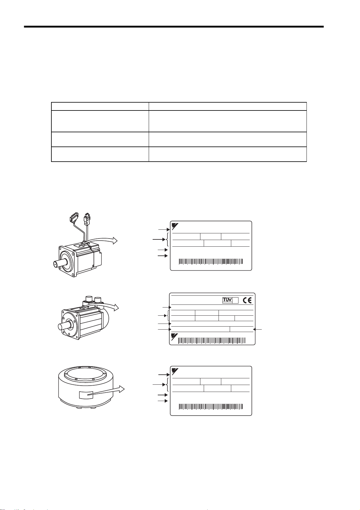
1.1.1 Check Items
1.1 Checking Products
The following procedure is used to check the AC servo drives of Σ-ΙΙ Series products on delivery.
1.1.1 Check Items
Check the following items when Σ-ΙΙ Series products are delivered.
Check Items Comments
Are the delivered products the ones
that were ordered?
Does the servomotor shaft rotate
smoothly?
Is there any damage?
If any of the above items are faulty or incorrect, contact your Yaskawa representative or the dealer from whom
you purchased the products.
1.1.2 Servomotors
Check the model numbers marked on the nameplates on the servomotor and SERVOPACK. (Refer to the descriptions of model numbers in
the following section.)
The servomotor shaft is normal if it can be turned smoothly by hand.
Servomotors with brakes, however, cannot be turned manually.
Check the overall appearance, and check for damage or scratches that
may have occurred during shipping.
1-2
Page 26

1
Outline
1.1.3 SERVOPACKs
AC SERVO MOTOR
TYPE
707 W
5.8 A
45 N m
200 V
150 min
CONT ins F
O/N 252909-101
S/N 842000045
YASKAWA ELECTRIC MADE IN JAPAN
DATE 0306
SGMCS-45M3A11
Servomotor model
Ratings
Serial number
Nameplate
-1
Order number
SGMCS (Middle-capacity series)
Serial
number
S/N
YASKAWA ELECTRIC
MADE IN JAPAN
412808-15-1
SERVOPACK
MODEL
AC-INPUT AC-OUTPUT
VOLTS
Hz
PHASE
AMPS
200-230
60/60
3
18.6
VOLTS
PHASE
AMPS
KU (MP)
0-230
3
24.8
3.0 (4.0)
SGDM-30ADA
SGDM for 30 W to 5.0 kW SGDM for 6.0 kW to 15.0 kW
SERVOPACK
model
Applicable
power supply
Applicable
motor
capacity
1.1 Checking Products
1-3
Page 27
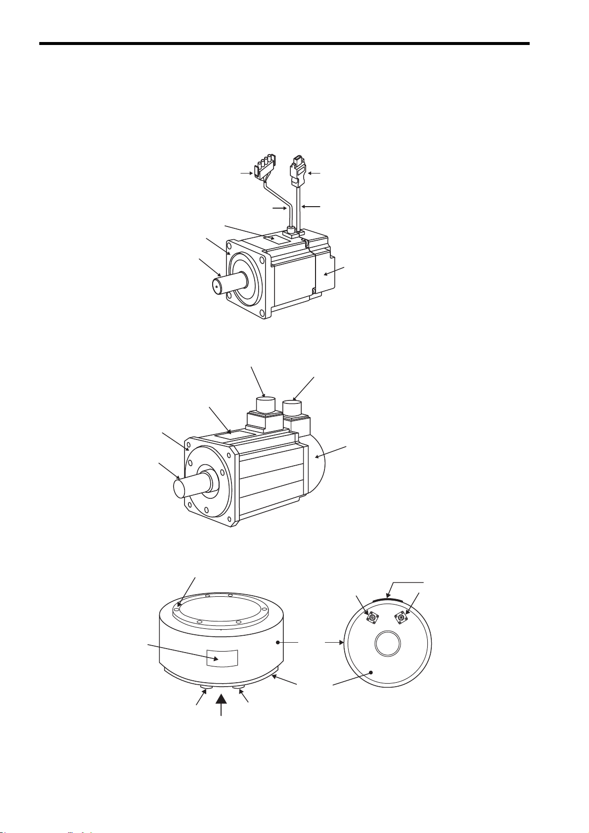
1 Outline
Flange
Output
shaft
Nameplate
Encoder connector
Servomotor connector
Servomotor
main circuit cable
Encoder
cable
Encoder
(Detecting section)
Flange
Nameplate
Encoder connector
Encoder
(Detecting section)
Servomotor connector
Output
shaft
1.2.1 Servomotors
1.2 Product Part Names
1.2.1 Servomotors
(1) SGMAH and SGMPH Without Gears and Brakes
(2) SGMGH/SGMSH/SGMDH Without Gears and Brakes
(3) SGMCS Direct-drive Motor (Small-capacity series)
Rotating axis
Encoder
connector
Nameplate
Servomotor
connector
1-4
Nameplate
Encoder
connector
A
Servomotor
connector
Frame
Mounting
flange
View
A
Page 28

1
Outline
(4) SGMCS Direct-drive (Middle-capacity series)
Rotating axis
Mounting flange
Frame
Motor connector
Encoder connector
Nameplate
1.2 Product Part Names
1-5
Page 29

1 Outline
Refer to 2.1 SERVOPACK Model
Designations.
With the front cover open
SERVOPACK model
Battery holder
Used to house the backup battery
for an absolute encoder.
Refer to 5.8.8 Absolute Encoder Battery,
8.4.3 Handing Batteries, and 8.4.4 Battery
Replacement Procedure.
YASKAWA
YASKAWA
SERVOPACK
SGDM-
MODE/SET
CHARGE POWER
DATA/
MODE/SET DATA/
CHARGE POWER
Panel display
5-digit, 7-segment LED used to display
SERVOPACK status, alarm status, and other
values when parameters are input.
Refer to 7.1.2 Key Names and Functions.
Panel operator
Charge indicator
Lights when the main circuit power supply is
ON and stays lit as long as the main circuit power
supply capacitor remains charged. Therefore,
do not touch the SERVOPACK even after the power
supply is turned OFF if the indicator is lit.
Main circuit power
supply terminals
Used for main circuit power supply input.
Refer to 6.1 Wiring Main Circuit.
Used for control power supply input.
Refer to 6.1 Wiring Main Circuit.
Control power supply terminals
Used to connect external regenerative resistors.
Refer to 6.5 Connecting Regenerative Resistors.
Regenerative
resistor connecting terminals
Refer to 6.1 Wiring Main Circuit.
Ground terminal
Be sure to connect to protect against electrical shock.
Servomotor terminals
Connects to the servomotor power line.
Refer to 6.1 Wiring Main Circuit.
CN5 Analog monitor connector
Used to monitor motor speed, torque
reference, and other values through
a special cable.
Refer to 5.8.3 Cables for Analog Monitor or
9.5 Analog Monitor.
CN8 Battery connector
Used to connect to the backup battery
for an absolute encoder.
Refer to 5.8.8 Absolute Encoder Battery,
8.4.3 Handing Batteries, and 8.4.4 Battery
Replacement Procedure.
Front cover
Power ON indicator
Lights when the control power supply is ON.
Panel keys
Used to set parameters.
Refer to 7.1.2 Key Names and Functions.
Refer to 5.8.1 Cables for Connecting Personal
Computer and 5.8.2 Digital Operator.
CN3 Connector for personal computer monitoring
and digital operator
Used to communicate with a personal computer
or to connect a digital operator.
CN1 I/O signal connector
Used for reference input signals and
sequence I/O signals.
Refer to 6.3 Examples of I/O Signal Connections.
Nameplate (side view)
Indicates the SERVOPACK model and ratings.
Refer to 1.1.3 SERVOPACKs.
CN2 Encoder connector
Connects to the encoder in the servomotor.
Refer to 6.2 Wiring Encoders.
INFO
1.2.2 SERVOPACKs
1.2.2 SERVOPACKs
(1) SGDM for 30 W to 5.0 kW
Connecting terminal of DC Reactor
For connecting a reactor, refer to 6.4.8 DC Reactor for Harmonic Suppression.
1-6
Page 30

1
Outline
(2) SGDM for 6.0 kW to 15.0 kW
L1 L2 L3
U
B2B1
+
VW
!
WARNING
MODE/SET DATA/
Ve r.
POWER
BATTERY
CHARGE
SGDM-
SERVOPACK 200V
YASKAWA
Panel display
Power indicator
Panel operator
Charge indicator
L1C
CN1 CN2
L2C
Main circuit power supply
terminals: L1, L2, L3
Servomotor terminals: U, V, W
Regenerative resistor
connecting terminals: B1, B2
CN3 Connector for
personal computer
monitoring and
digital operator
CN8 Battery connector
CN5 Analog
monitor connector
Panel switch
Battery holder
Nameplate (side view)
CN2 Encoder connector
CN1 I/O signal connector
Control circuit
terminal
SERVOPACK model
Ground terminal
CN8
CN5
CN3
∗
∗
1.2 Product Part Names
* Control circuit terminal and regenerative resistor connecting terminals differ the position of the terminal block by
the SERVOPACK model.
Refer to Chapter 4 SERVOPACK Specifications and Dimensional Drawings for details.
SERVOPACK Model Reference
SGDM-60ADA, 75ADA 4.7.7, 4.9.1
SGDM-1AADA, 1EADA 4.7.8, 4.9.2
1-7
Page 31

1 Outline
Noise filter
Molded-case
circuit breaker
(MCCB)
Protects the power supply
line by shutting the
circuit OFF when
overcurrent is detected.
(Refer to 5.8.9.)
Used to eliminate
external noise from the
power line.
(Refer to 5.8.10.)
(
Refer to
5.8.1.)
Servomotor
SGMH
SGDM-AD
SGDM-ADA
SGDM-BD
SGDM-BDA
SERVOPACK
Power supply
Single-phase 100/200 VAC
R T
C
N
3
C
N
1
L1C
L2C
B1
B2
U
V
W
L1
L2
+
1
MODE/SET
DATA/
CHARGE POWER
C
N
SGDM-
SERVOPACK
200V
YASKAWA
+ 2
-
Regenerative
resistor
Magnetic
contactor
Connect an external
regenerative resistor
to terminals B1 and
B2 if the regenerative
capacity is insufficient.
(Refer to 5.8.6.)
Turns the servo
ON and OFF.
Install a surge
absorber.
(Refer to 5.8.11.)
Brake power
supply
Magnetic
contactor
Used for a
servomotor
with a brake.
(Refer to 5.8.5.)
Turns the brake
power supply
ON or OFF.
Install a surge
absorber.
(Refer to 5.8.11.)
Servomotor
main circuit cable
(Refer to 5.1, 5.2.)
Encoder cable
(
Refer to
5.4, 5.5.)
Host controller
(
Refer to
5.7.)
I/O signal cable
Personal computer
Connection cable
for digital operator
Connection cable
for personal computer
Digital
operator
(
Refer to
5.8.2.)
(
Refer to
5.8.2.)
∗
∗
For connecting a DC reactor, refer to 6.4.8 DC Reactor
for Harmonic Suppression.
1.3.1 Single-phase, 100 V and 200 V Main Circuit
1.3 Examples of Servo System Configurations
1.3.1 Single-phase, 100 V and 200 V Main Circuit
This section describes examples of basic servo system configuration.
1-8
Page 32

1
Outline
1.3.2 Three-phase, 200 V Main Circuit
Noise filter
Molded-case
circuit breaker
(MCCB)
Power supply
Three-phase 200 VAC
Protects the power supply
line by shutting the
circuit OFF when
overcurrent is
detected.
(Refer to 5.8.9.)
Used to eliminate
external noise from the
power line.
(Refer to 5.8.10.)
R S T
L1
L2
L3
U
V
W
L1C
L2C
B1
B2
B3
1
2
C
N
3
C
N
1
C
N
2
MODE/SET
DATA/
CHARGE POWER
YASKAWA
SERVOPACK
SGDM-
200V
Magnetic
contactor
SGDM-AD
SGDM-ADA
SERVOPACK
Turns the servo
ON and OFF.
Install a surge
absorber.
(Refer to
5.8.11.)
Brake power supply
Magnetic
contactor
Regenerative
resistor
Connect an external
regenerative resistor
to terminals B1 and B2
if the regenerative capacity
is insufficient.
(Refer to 5.8.6.)
Used for a servomotor with a brake.
(Refer to 5.8.5.)
Turns the brake power supply
ON and OFF.
Install a surge absorber.
(Refer to 5.8.11.)
∗2
∗1
∗3
Servomotor
main circuit cable
Encoder cable
SGMH
Servomotor
(Refer to 5.1, 5.2.)
(Refer to 5.4, 5.5.)
Host controller
I/O signal cable
(Refer to 5.7.)
(Refer to 5.8.1.)
Connection cable
for digital operator
Connection cable
for personal computer
Personal computer
(Refer to 5.8.2.)
Digital
operator
(Refer to 5.8.2.)
∗2
∗1
∗3
The main circuit positive-side terminal is only available
to use at three-phase 200 VAC, 6 kW SERVOPACK.
Do not use 1 or 2.
Be sure to disconnect the lead between B2 and
B3, before connecting an external regenerative
registor to the SERVOPACK.
For connecting a DC reactor, refer to 6.4.8 DC Reactor
for Harmonic Suppression.
1.3 Examples of Servo System Configurations
1-9
Page 33

1 Outline
A
View A
Servomotor
main circuit cable
Encoder
cable
SGDM-ADA
SERVOPACK
SGMCS Servomotor
R T
Nameplate
(Refer to 5.7.)
(Refer to 5.8.1.)
C
N
3
C
N
1
L1C
L2C
B1
B2
U
V
W
L1
L2
+
1
MODE/SET
DATA/
CHARGE POWER
C
N
SGDM-
SERVOPACK
200V
YASKAWA
+ 2
-
Noise filter
Molded-case
circuit breaker
(MCCB)
Protects the power supply
line by shutting the
circuit OFF when
overcurrent is
detected.
(Refer to 5.8.9.)
Used to eliminate
external noise from the
power line.
(Refer to 5.8.10.)
Magnetic
contactor
Turns the
servo ON
and OFF.
Install a surge
absorber.
(Refer to
5.8.11.)
Regenerative
resistor
Connect an external
regenerative resistor
to terminals B1 and B2
if the regenerative
capacity is insufficient.
(Refer to 5.8.6.)
Servomotor
main circuit cable
(Refer to 5.1, 5.2.)
Encoder cable
(Refer to 5.4, 5.5.)
For connecting a DC reactor, refer to 6.4.8 DC Reactor for
Harmonic Suppression.
Note:
Connection cable
for personal computer
Connection cable
for digital operator
Personal computer
(Refer to 5.8.2.)
Digital
operator
(Refer to 5.8.2.)
Host controller
I/O signal cable
Power supply
Single-phase or
Three-phase
100/200VAC
1.3.3 Connecting to SGMCS Servomotor
1.3.3 Connecting to SGMCS Servomotor
1-10
Page 34

1
Outline
1.4 Applicable Standards
U
L
C
R
US
LISTED
C
R
US
Σ-II Series servo drives conform to the following overseas standards.
1.4.1 North American Safety Standards (UL, CSA)
1.4 Applicable Standards
SERVOPACK • SGDM
Servomotor
* 1. Underwriters Laboratories Inc.
* 2. Canadian Standards Association.
1.4.2 CE Marking
SERVOPACK • SGDM
Servomotor
Model
• SGMAH
• SGMPH
• SGMGH
• SGMSH
• SGMDH
• SGMCS
Model
• SGMAH
• SGMPH
• SGMGH
• SGMSH
• SGMDH
• SGMCS
∗1
UL
Standards (UL File No.) CSA∗2 Standards
UL508C(E147823)
UL1004(E165827)
Low Voltage
Directive
EN50178
IEC60034-1
IEC60034-5
IEC60034-8
IEC60034-9
EMI EMS
EN55011
group 1 class A
CSA C22.2
No.14
CSA C22.2
No.100
EMC Directive
EN50082-2
or
EN61000-6-2
Certifications
UL
Certifications
TÜV PS
∗
* TÜV Product Services GmbH
Note: For installation conditions, refer to 6.4.2 Wiring for Noise Control.
Because SERVOPACKs and servomotors are built-in type, reconfirmation is required after being
installed in the final product.
1-11
Page 35

1 Outline
1.5 Σ-II Series SGDM SERVOPACK Upgraded Functions
The following functions have been added or upgraded on the SGDM SERVOPACK with software version 32 or
later.
Refer to the following table for the added or improved functions for each model.
Function Item Description
Applicable capacity range
Speed feed forward
Torque limit using
an external torque
limit and analog
voltage reference
Input signal polarity reversal
Output signal
polarity reversal
Multiturn limit setting
“Multiturn limit
disagreement”
alarm detection
Average movement filter of position reference
Notch filter
Second stage notch
filter and changeable Q value
Direct-drive motor
for SGMCS
Single-turn data for
absolute encoder
Enhanced dividing
output resolution
Reference pulse
input multiplication
switching
30W to 3.0 KW
30W to 15.0 kW
In the position control mode, the
speed feed forward reference
using an analog voltage can be
input by the speed reference (VREF) input.
To enable the torque limit function using analog voltage reference only when either /P-CL or /
N-CL signal is ON.
To reverse the “Enabled” logic
polarity of sequence input signal
To reverse the “Enabled” logic
polarity of sequence output signal
To set the upper limit of multiturn
data when using an absolute
encoder.
To detect the alarm A.CC when
the multiturn limit value set in the
encoder does not agree with that
in the SERVOPACK.
To filter the position reference
pulse of constant frequency inside
the SERVOPACK. Either acceleration/deceleration filter or average movement filter can be
selected.
Filtering function to suppress
vibration according to the
machine’s vibration frequency.
A second stage notch filter is
added. And the Q value (sharpness of notching) can be changed.
Applicable to the SGMCS directdrive motors
Adapted to single-turn data absolute encoders that are mounted on
direct-drive motors as standard
The upper limit of diving output
16384 [P/R] (equivalent to 16-bit)
of feedback pulse is increased to
262144 [P/R] (equivalent to 20bit).
The reference pulse multiplication can be selected from 1 to 99.
Software Version
31 or earlier
Applicable Applicable −
N/A Applicable −
N/A Applicable 9.4.3
N/A Applicable 8.9.4
N/A Applicable 7.3.2
N/A Applicable 7.3.3
N/A Applicable 8.4.7
N/A Applicable 8.4.8
N/A Applicable 8.6.4
N/A Applicable 9.4.10
N/A Applicable 10.3.4
N/A Applicable 10.3.1
N/A Applicable 10.4.2
N/A Applicable 10.3.2
N/A Applicable 10.3.3
Software Version
32 or later
Reference
Section
1-12
Page 36

1.5 Σ-II Series SGDM SERVOPACK Upgraded Functions
1
Outline
Function Item Description
The switching between Gain Set-
Automatic gain
switching
Increase moment of
inertia ratio range
Read serial number and date of
manufacture
* SigmaWin+ is a Windows-compatible software tool used to set up and tune Yaskawa servo drives. SigmaWin+
can be downloaded from the e-mechatronics site (http://www.e-mechatronics.com/en).
ting 1 and Gain Setting 2 is automatically carried out according to
the conditions of position reference and position error.
The setting range “0 to 10,000%”
of moment of inertia ratio is
extended to “0 to 20,000%”.
The serial number and manufacture for the data of SERVOPACK
can be read with “SigmaWin+ *.”
Software Version
31 or earlier
N/A Applicable 10.3.5
N/A Applicable 10.4.1
N/A Applicable 10.4.3
Software Version
32 or later
Reference
Section
(Cont’d)
1-13
Page 37

2
Selections
2
Selections
2.1 Servomotor Model Designations - - - - - - - - - - - - - - - - - - - - - - - - - - - - - - 2-2
2.1.1 Model SGMAH (3000 min-1) - - - - - - - - - - - - - - - - - - - - - - - - - - - - - - - - - - - - - - - - - - 2-2
2.1.2 Model SGMPH (3000 min-1) - - - - - - - - - - - - - - - - - - - - - - - - - - - - - - - - - - - - - - - - - - 2-4
2.1.3 Model SGMGH (1500 min-1) - - - - - - - - - - - - - - - - - - - - - - - - - - - - - - - - - - - - - - - - - - 2-6
2.1.4 Model SGMGH (1000 min-1) - - - - - - - - - - - - - - - - - - - - - - - - - - - - - - - - - - - - - - - - - - 2-8
2.1.5 Model SGMSH (3000 min-1) - - - - - - - - - - - - - - - - - - - - - - - - - - - - - - - - - - - - - - - - - 2-10
2.1.6 Model SGMDH (2000 min-1) - - - - - - - - - - - - - - - - - - - - - - - - - - - - - - - - - - - - - - - - - 2-12
2.1.7 Model SGMCS - - - - - - - - - - - - - - - - - - - - - - - - - - - - - - - - - - - - - - - - - - - - - - - - - - 2-13
2.2 SERVOPACK Model Designations - - - - - - - - - - - - - - - - - - - - - - - - - - - - 2-14
2.3 Σ-II Series SERVOPACKs and Applicable Servomotors - - - - - - - - - - - - - 2-15
2.3.1 SGDM SERVOPACKs and SGMH Servomotors - - - - - - - - - - - - - - - - - - - - - - - - - 2-15
2.3.2 SGDM SERVOPACKs and SGMCS Servomotors - - - - - - - - - - - - - - - - - - - - - - - - - - 2-16
2.4 Selecting Cables - - - - - - - - - - - - - - - - - - - - - - - - - - - - - - - - - - - - - - - - 2-17
2.4.1 Cables for SGMAH and SGMPH Servomotors - - - - - - - - - - - - - - - - - - - - - - - - - - - - 2-17
2.4.2 Cables for SGMGH/SGMSH/SGMDH Servomotors - - - - - - - - - - - - - - - - - - - - - - - - 2-20
2.4.3 Cables for SGMCS Servomotors - - - - - - - - - - - - - - - - - - - - - - - - - - - - - - - - - - - - - 2-23
2.5 Selecting Peripheral Devices - - - - - - - - - - - - - - - - - - - - - - - - - - - - - - - - 2-26
2.5.1 Special Options - - - - - - - - - - - - - - - - - - - - - - - - - - - - - - - - - - - - - - - - - - - - - - - - - - 2-26
2.5.2 Molded-case Circuit Breaker and Fuse Capacity - - - - - - - - - - - - - - - - - - - - - - - - - - 2-28
2.5.3 Noise Filters, Magnetic Conductors, Surge Absorbers and DC Reactors - - - - - - - - - 2-29
2.5.4 Regenerative Resistors and Brake Power Supply Units - - - - - - - - - - - - - - - - - - - - - - 2-30
2-1
Page 38

2 Selections
SGMAH − 02 A A A 2 1
4th digit: Serial Encoder
7th digit: Brake and Oil Seal
Code
1
B
C
D
E
S
Specifications
Without brake
With 90-VDC brake
With 24-VDC brake
With oil seal and 90-VDC brake
With oil seal and 24-VDC brake
With oil seal
1st + 2nd digits:
Rated Output
(kW)
Code
A3
A5
01
02
04
08
Rated Output
0.03
0.05
0.1
0.2
0.4
0.75
A
ޚ
ޚ
ޚ
ޚ
ޚ
ޚ
B
ޚ
ޚ
ޚ
ޚ
−
−
3rd digit:
Voltage
A:200V,B:100V
Code
1
4
A
B
Remarks
Standard
Standard
Option
ޓޓSpecifications
16-bit absolute encoder
16-bit absolute encoder
with super capacitor
13-bit incremental encoder
16-bit incremental encoder
∗1. The number of encoder pulses: 16384 P/Rev.
∗2. The number of encoder pulses: 2048 P/Rev.
: Available
Option
∗1
∗1
∗1
∗2
5th digit: Design Revision Order
Code
A
Specifications
Standard
6th digit: Shaft End
Code
2
4
6
8
Remarks
Standard
Option
ޓޓSpecifications
Straight without key
Straight with key
Straight with key and tap
Straight with tap
1st +
2nd
digits
3rd
digit
4th
digit
5th
digit
6th
digit
7th
digit
D
8th digit: Connector
Code
Blank
D
Specifications
Standard
Waterproof connector
8th
digit
2.1.1 Model SGMAH (3000 min
-1
)
2.1 Servomotor Model Designations
This section explains how to check the servomotor model and ratings. The alphanumeric codes after SGMH
indicate the specifications.
2.1.1 Model SGMAH (3000 min-1)
(1) Without Gears
2-2
Page 39

2
Selections
(2) With Gears
SGMAH
−
01 A A H 1 2 BA
1st + 2nd digits:
Rated Output
(kW)
Code
A3
A5
01
02
04
08
Rated Output
0.03
0.05
0.1
0.2
0.4
0.75
A
B
−
−
3rd digit: Voltage
A:200V,B:100V
4th digit: Serial Encoder
Remarks
Standard
Option
Standard
Option
ޓޓSpecifications
16-bit absolute encoder
16-bit absolute encoder
with super capacitor
13-bit incremental encoder
16-bit incremental encoder
∗1
∗1
∗1
∗2
5th digit:
Design Revision Order
Code
A
Specifications
Standard
9th digit: Brake
Code
1
B
C
ޓ
Specifications
Without brake
With 90-VDC brake
With 24-VDC brake
The number of encoder pulses: 16384 P/Rev.
The number of encoder pulses: 2048 P/Rev.
: Available
1st +
2nd
digits
3rd
digit
4th
digit
5th
digit
6th
digit
7th
digit
8th
digit
9th
digit
∗1
∗2
D
10th digit: Connector
Code
Blank
D
Specifications
Standard
Waterproof connector
10th
digit
6th digit:
Gear Type
7th digit:
Gear Ratio
8th digit: Shaft End
2 (Straight without key)
6 (Straight with key and tap)
8 (Straight with tap)
G
(Low-
backlash
Gear)
H
(Low-
backlash
Gear)
J
(Standard
Backlash
Gear)
1 (1/5)
3 (3/31)
7 (1/33)
C (1/21)
1 (1/5)
2 (1/9)
7 (1/33)
B (1/11)
C (1/21)
1 (1/5)
2 (1/9)
7 (1/33)
B (1/11)
C (1/21)
−
−
−
−
−
−
−
−
−
−
−
−
−
−
−
−
−
−
−
−
−
−
−
−
−
−
−
−
−
−
−
−
0
(No Shaft)
0
(No Shaft)
Rated Output: A3, A5
(0.03 kW, 0.05 kW)
Rated Output: 01 to 08
(0.1 kW to 0.75 kW)
∗3
2 (Straight without key)
6 (Straight with key and tap)
8 (Straight with tap)
∗3
: Available
Shaft end specification 8 (straight with tap) is available only for SGMAH servomotors with low-backlash gears.
∗3
Code
1
4
A
B
2.1 Servomotor Model Designations
2-3
Page 40

2 Selections
SGMPH − 02 A A A 2 1
1st + 2nd digits:
Rated Output
(kW)
Code
01
02
04
08
15
Rated Output
0.1
0.2
0.4
0.75
1.5
A
ޚ
ޚ
ޚ
ޚ
ޚ
B
ޚ
ޚ
−
−
−
3rd digit
: Voltage
A:200V,B:100V
Specifications
Standard
IP67 water-proof specifications
Code
A
E
4th digit:
Serial Encoder
Code
1
4
A
B
Remarks
Standard
Standard
Option
ޓSpecifications
16-bit absolute encoder
16-bit absolute encoder
with super capacitor
13-bit incremental encoder
16-bit incremental encoder
The number of encoder pulses: 16384 P/Rev.
The number of encoder pulses: 2048 P/Rev.
Option
∗1
∗1
∗1
∗2
∗1
∗2
5th digit: Design Revision Order
6th digit: Shaft End
Code
2
4
6
8
Remarks
Standard
Option
ޓޓSpecifications
Straight without key
Straight with key
Straight with key and tap
Straight with tap
7th digit: Brake and Oil Seal
Code
1
B
C
D
E
S
Specifications
Without options
With 90-VDC brake
With 24-VDC brake
With oil seal and 90-VDC brake
With oil seal and 24-VDC brake
With oil seal
1st +
2nd
digits
3rd
digit
4th
digit
5th
digit
6th
digit
7th
digit
: Available
D
8th digit: Connector
Code
Blank
D
Specifications
Standard
Waterproof connector
8th
digit
2.1.2 Model SGMPH (3000 min
-1
)
2.1.2 Model SGMPH (3000 min-1)
(1) Without Gears
2-4
Page 41

2
Selections
(2) With Gears
SGMPH
−
01 A A H 1 2 BA
1st + 2nd digit:
Rated Output
(kW)
Code
01
02
04
08
15
Rated Output
0.1
0.2
0.4
0.75
1.5
A
B
−
−
−
3rd digit:
Voltage
A:200V,B:100V
4th digit:
Serial Encoder
Code
1
4
A
B
Remarks
Standard
Option
Standard
Option
ޓSpecifications
16-bit absolute encoder
16-bit absolute encoder
with super capacitor
13-bit incremental encoder
16-bit incremental encoder
The number of encoder pulses: 16384 P/Rev.
The number of encoder pulses: 2048 P/Rev.
∗1
∗1
∗2
∗1
∗2
Specifications
Standard
IP67 water-proof specifications
Code
A
E
5th digit:
Design Revision Order
9th digit:
Brake
Code
1
B
C
ޓSpecifications
Without brake
With 90-VDC brake
With 24-VDC brake
1st +
2nd
digits
3rd
digit
4th
digit
5th
digit
6th
digit
7th
digit
8th
digit
9th
digit
: Available
∗1
D
10th digit:
Connector
Code
Blank
D
Specifications
Standard
Waterproof connector
10th
digit
7th digit:
Gear Ratio
6th digit:
Gear Type
G
(Low-
backlash
Gear)
H
(Low-
backlash
Gear)
J
(Standard
Backlash
Gear)
Rated Output: 01, 02, 04, 08
(0.1 kW to 0.75 kW)
Rated Output: 15
(1.5 kW)
0
(No Shaft)
2 (Straight without key)
6 (Straight with key and tap)
8 (Straight with tap)
0
(No Shaft)
8th digit:
Shaft End
2 (Straight without key)
6 (Straight with key and tap)
8 (Straight with tap)
: Available
Shaft end specification 8 (straight with tap) is available only for SGMPH servomotors with low-backlash gears.
∗3
1 (1/5)
3 (3/31)
7 (1/33)
C (1/21)
1 (1/5)
7 (1/33)
B (1/11)
C (1/21)
1 (1/5)
7 (1/33)
B (1/11)
C (1/21)
−
−
−
−
−
−
−
−
−
−
−
−
−
−
−
−
−
−
−
−
−
−
−
−
2.1 Servomotor Model Designations
2-5
Page 42

2 Selections
SGMGH−13 A C A 2 1
∗
∗
∗
∗
1st + 2nd digits:
Rated Output (kW)
Code
05
09
13
20
30
44
55
75
1A
1E
Rated Output
0.45
0.85
1.3
1.8
2.9
4.4
5.5
7.5
11. 0
15.0
A
3rd digit: Voltage
A:200V
5th digit: Design Revision Order
6th digit: Shaft End
Code
2
3
5
6
Remarks
Standard
Option
ޓޓSpecifications
Straight without key
Taper 1/10, with parallel key
Taper 1/10, with woodruff key
Straight with key and tap
4th digit: Serial Encoder
Code
2
C
Remarks
ޓSpecifications
17-bit absolute encoder
17-bit incremental encoder
Code
A
C
ޓ
Specifications
Standard
For high-performance machine tool
Standard
∗
The number of encoder pulses: 32768 P/Rev.
∗
Applicable only for models SGMGH-05 to -44.
∗
Applicable only for models SGMGH-05 and 09.
7th digit: Brake and Oil Seal
Code
1
B
C
D
E
S
Specifications
Without options
With 90-VDC brake
With 24-VDC brake
With oil seal and 90-VDC brake
With oil seal and 24-VDC brake
With oil seal
1st +
2nd
digits
3rd
digit
4th
digit
5th
digit
6th
digit
7th
digit
: Available
2.1.3 Model SGMGH (1500 min
-1
)
2.1.3 Model SGMGH (1500 min-1)
(1) Without Gears
2-6
Page 43

2
Selections
(2) With Gears
SGMGH
−
20 A A L 1 4 BC
6th digit: Gear Type
Code
L
E
F
ޓ
Specifications
Planetary low-backlash gear (Flange type)
Standard backlash gear (Foot mounting type)
Standard backlash gear (
Flange type)
8th digit: Shaft End
6th digit:
Gear Type Code
Code
4
6
E
−
F
−
L
−
ޓޓ
Specifications
Straight with key
Straight with key and tap
75P
−
6th digit: Gear
Type Code
L
1
2
5
7
8
1/5
1/9
1/20
1/29
1/45
05A
09A
13A
20A
−
30A
−
−
44A
−
−
−
1st + 2nd + 3rd digits: Code of the Rated Output and Voltage7th digit: Gear Ratio
Code Specifications
4th digit: Serial Encoder
Code
2
C
Remarksޓޓޓ Specifications
17-bit absolute encoder
17-bit incremental encoder
Code
A
C
Specifications
Standard
For high-performance machine tool
(Low-
backlash)
The number of encoder pulses: 32768 P/Rev.
∗
Applicable only for models SGMGH-05 to -44.
∗
With standard backlash gears: P
∗
5th digit: Design Revision Order
9th digit: Brake
Code
1
B
C
ޓ
Specifications
Without brake
With 90-VDC brake
With 24-VDC brake
∗
∗
∗
∗
Standard
1st +
2nd
digits
3rd
digit
4th
digit
5th
digit
6th
digit
7th
digit
8th
digit
9th
digit
1st + 2nd digits:
Rated Output
(kW)
Code
05
09
13
20
30
44
55
75
1A
Rated Output
0.45
0.85
1.3
1.8
2.9
4.4
5.5
7.5
11. 0
A
3rd digit: Voltage
A:200V
: Available
: Available
: Available
: Available
: Available
6th digit: Gear
Type Code
E
A
B
C
7
1/6
1/11
1/21
1/29
05P
09P
13P
20P
30P
44P
1st + 2nd + 3rd digits: Code of the Rated Output and Voltage7th digit: Gear Ratio
Code Specifications
(Standard)
55P
75P
−
6th digit: Gear
Type Code
F
A
B
C
7
1/6
1/11
1/21
1/29
05P
09P
13P
20P
30P
44P
1st + 2nd + 3rd digits: Code of the Rated Output and Voltage7th digit: Gear Ratio
Code Specifications
(Standard)
1AP
−
1AP
−
55P
2.1 Servomotor Model Designations
2-7
Page 44

2 Selections
∗
∗
∗
∗
1st + 2nd digits:
Rated Output
(kW)
4th digit: Serial Encoder
Code
2
C
RemarksޓޓޓSpecifications
17-bit absolute encoder
17-bit incremental encoder
Standard
The number of encoder pulses: 32768 P/Rev.
∗
Applicable only for models SGMGH-03 and -06.
∗
Applicable only for models SGMGH-03 to -30.
∗
Code
03
06
09
12
20
30
40
55
Rated Output
0.3
0.6
0.9
1.2
2.0
3.0
4.0
5.5
A
ޚ
ޚ
ޚ
ޚ
ޚ
ޚ
ޚ
ޚ
5th digit: Design Revision Order
Code
B
D
Specifications
Standard
For high-performance machine tool
SGMGH − 12 A C B 2 1
7th digit: Brake and Oil Seal
Code
1
B
C
D
E
S
Specifications
Without options
With 90-VDC brake
With 24-VDC brake
With oil seal and 90-VDC brake
With oil seal and 24-VDC brake
With oil seal
3rd digit: Voltage
A: 200V
6th digit: Shaft End
Code
2
3
5
6
Remarks
Standard
Option
ޓޓSpecifications
Straight without key
Taper 1/10, with parallel key
Taper 1/10, with woodruff key
Straight with key and tap
1st +
2nd
digits
3rd
digit
4th
digit
5th
digit
6th
digit
7th
digit
: Available
2.1.4 Model SGMGH (1000 min
-1
)
2.1.4 Model SGMGH (1000 min-1)
(1) Without Gears
2-8
Page 45

2
Selections
(2) With Gears
SGMGH
−
20 A B L 1 4 BC
6th digit: Gear Type
Code
L
E
F
Specifications
Planetary low-backlash gear (Flange type)
Standard backlash gear (Foot mounting type)
Standard
backlash gear (Flange type)
8th digit: Shaft End
6th digit:
Gear Type Code
Code
4
6
E
−
F
−
L
−
ޓޓ
Specifications
Straight with key
Straight with key and tap
E
F
4th digit: Serial Encoder
Code
2
C
Remarksޓޓޓ Specifications
17-bit absolute encoder
17-bit incremental encoder
Code
B
D
Specifications
Standard
For high-performance machine tool
∗
(Standard)
(Standard)
Specifications
Specifications
Code
Code
The number of encoder pulses: 32768 P/Rev.
∗
5th digit: Design Revision Order
9th digit: Brake
Code
1
B
C
ޓ
Specifications
Without brake
With 90-VDC brake
With 24-VDC brake
∗
∗
A
B
C
7
1/6
1/11
1/21
1/29
03P
06P
09P
12P
20P
30P
40P
55P
−
03P
06P
09P
12P
20P
30P
40P
55P
−
A
B
C
7
1/6
1/11
1/21
1/29
Standard
1st +
2nd
digits
3rd
digit
4th
digit
5th
digit
6th
digit
7th
digit
8th
digit
9th
digit
6th digit: Gear
Type Code
1st + 2nd + 3rd digits: Code of the Rated Output and Voltage
7th digit: Gear Ratio
6th digit: Gear
Type Code
1st + 2nd + 3rd digits: Code of the Rated Output and Voltage
7th digit: Gear Ratio
1st + 2nd digits:
Rated Output
(kW)
Code
03
06
09
12
20
30
40
55
Rated Output
0.3
0.6
0.9
1.2
2.0
3.0
4.0
5.5
A
3rd digit: Voltage
A:200V
: Available
: Available
: Available
: Available
: Available
With standard backlash gears: P
∗
Applicable only for models SGMGH-03 to -30.
∗
∗
6th digit: Gear
Type Code
L
1
2
5
7
8
1/5
1/9
1/20
1/29
1/45
03A
06A
09A
12A
20A
−
−
30A
−
−
−
40A
−
−
−
−
−
55A
−
−
−
−
−
1st + 2nd + 3rd digits: Code of the Rated Output and Voltage
7th digit: Gear Ratio
Code
Specifications
(Low-
backlash)
2.1 Servomotor Model Designations
2-9
Page 46

2 Selections
∗
∗
1st + 2nd digits:
Rated Output
(kW)
4th digit: Serial Encoder
Code
2
C
Remarks Specifications
17-bit absolute encoder
17-bit incremental encoder
Standard
The number of encoder pulses: 32768 P/Rev.
∗
SGMSH − 10 A C A 2 1
7th digit: Brake and Oil Seal
Code
1
B
C
D
E
S
Specifications
Without options
With 90-VDC brake
With 24-VDC brake
With oil seal and 90-VDC brake
With oil seal and 24-VDC brake
With oil seal
Code
10
15
20
30
40
50
Rated Output
1.0
1.5
2.0
3.0
4.0
5.0
A
3rd digit: Voltage
A:200V
5th digit: Design Revision Order
Code
A
Specifications
Standard
6th digit: Shaft End
Code
2
3
6
ޓRemarks
Standard
ޓޓޓSpecifications
Straight without key
Taper 1/10, with parallel key
Straight with key and tap
Option
1st +
2nd
digits
3rd
digit
4th
digit
5th
digit
6th
digit
7th
digit
: Available
2.1.5 Model SGMSH (3000 min
-1
)
2.1.5 Model SGMSH (3000 min-1)
(1) Without Gears
2-10
Page 47

2
Selections
(2) With Gears
1st +
2nd
digits
3rd
digit
4th
digit
5th
digit
6th
digit
7th
digit
8th
digit
2.1 Servomotor Model Designations
9th
digit
SGMSH
1st + 2nd digits:
Rated Output
(kW)
Rated Output
Code
10
15
20
30
40
50
{: Available
Code
2
C
∗
The number of encoder pulses: 32768 P/Rev.
1.0
1.5
2.0
3.0
4.0
5.0
4th digit: Serial Encoder
Specifications
17-bit absolute encoder
17-bit incremental encoder
10 A A L 1 4 BC
−
3rd digit: Voltage
A:200V
A
{
{
{
{
{
{
∗
Remarks
Standard
∗
Code
1
B
C
8th digit: Shaft End
Code4 Specifications
Straight with key
6th digit:
7th digit: Gear Ratio
Gear
Type
Code
Code
L
(Low-
backlash)
{: Available
1
2
5
7
8
Specifications
1/5
1/9
1/20
1/29
1/45
9th digit: Brake
Specifications
Without brake
With 90-VDC brake
With 24-VDC brake
1st + 2nd + 3rd digits:
Code of the Rated Output and Voltage
10A
15A
{
{
{
{
{
{
{
{
{
{
20A
{
{
{
{
{
30A
{
{
{
{
{
40A
{
{
{
{
−
50A
{
{
{
−
−
5th digit: Design Revision Order
Specifications
Code
Standard
A
6th digit: Gear Type
CodeL Specifications
Planetary low-backlash gear (Flange type)
2-11
Page 48

2 Selections
SGMDH − 22 A C A 2 B
7th digit: Brake and Oil Seal
Code
1
B
C
D
E
S
Specifications
Without options
With 90-VDC brake
With 24-VDC brake
With oil seal and 90-VDC brake
With oil seal and 24-VDC brake
With oil seal
CodeA Specifications
Standard
6th digit: Shaft End
Code
2
6
ޓ
Remarks
Standard
Option
ޓޓޓSpecifications
Straight without key
Straight with key and tap
Code
22
32
40
Rated Output
2.2
3.2
4.0
A
Remarks
Option
Standard
Option
Option
Option
Option
1st +
2nd
digits
3rd
digit
4th
digit
5th
digit
6th
digit
7th
digit
Code
2
C
Remarks
Standard
5th digit: Design Revision Order
∗
∗
1st + 2nd digits:
Rated Output
(kW)
4th digit: Serial Encoder
Specifications
17-bit absolute encoder
17-bit incremental encoder
3rd digit: Voltage
A:200V
: Available
The number of encoder pulses: 32768 P/Rev.
∗
2.1.6 Model SGMDH (2000 min
-1
)
2.1.6 Model SGMDH (2000 min-1)
• SGMDH servomotors are provided with 90-VDC brakes as standard.
(The seventh digit: B)
• Servomotors with backlash gears are not available for the model SGMDH.
2-12
Page 49

2
Selections
2.1.7 Model SGMCS
1st +
2nd
digits
3rd
digit
4th
digit
5th
digit
6th
digit
7th
digit
SGMCS − 02 B 3 C 1 1
02
04
05
07
08
10
14
16
17
25
35
45
80
1A
1E
2Z
2.0
4.0
5.0
7.0
8.0
10.0
14.0
16.0
17.0
25.0
35.0
45.0
80.0
110.0
150.0
200.0
SGMCS
Direct-drive motor
B
(φ135)C(φ175)D(φ230)E(φ290)M(φ280)N(φ360)
4th digit: Encoder
Code
3
D
Specifications
20-bit abs
olute encoder
(Single-turn data absolut
e encoder)
20-bit incremental encoder
7th digit: Brake
Code
1
Specifications
Without brake
1st + 2nd digits:
Rated Torque (Nm)
3rd digit: Servomotor Outer Diameter (mm)
Code
Specifi-
cations
Remarks
Standard
Option
5th digit: Design Revision Order
Code
A
B
C
Specifications
Servomotor outer diameter M, N
Servomotor outer diameter E
Servomotor outer diameter B, C, D
6th digit: Flange
Code
1
3
4
Specifications
C-face
*1
C-face
*2
C-face with cable on side
*3
C-face on the opposite drive end
(servomotor outer diameter B, C, D, E)
C-face on the drive end
(servomotor outer diameter M, N)
C-face on the opposite drive end
(servomotor outer diameter M, N)
Only for servomotor outer diameter B, C, D, E
∗1
∗2
∗3
2.1 Servomotor Model Designations
2-13
Page 50

2 Selections
A
1st +
2nd
digits
3rd
digit
4th
digit
5th
digit
Code
A3
A5
01
02
04
05
08
10
Rated Output
0.03
0.05
0.10
0.20
0.40
0.45
0.75
1.0
Code
15
20
30
50
60
75
1A
1E
Rated Output
1.5
2.0
3.0
5.0
6.0
7.5
11. 0
15.0
4th digit: Model (Fixed)
Code
D
Remarks
For torque, speed, and position control
Code
A
B
Voltage
6th digit: Option
Code
−
-P
-R
Specificatioins
Base-mounted
Duct-ventilated
Rack-mounted
Rated Output of
Applicable Servomotor (kW)
0.03 to 15.0kW
6.0 to 15.0kW
0.03 to 5.0kW
10SGDM - D
Single/Three-phase 200V
Single-phase 100V *
5th digit: Design Revision Order *
Blank or A,
* The SGMAH and SGMPH Servomotors of 200W
or less can be used with a 100V SERVOPACK.
6th
digit
1st + 2nd digits:
Rated Output of Applicable Servomotor (kW)
3rd digit: Power Supply Voltage
* Refer to 1.5 Σ-II Series SGDM SERVOPACK Upgraded Functions
for more information on the specification variances for different
design revision order.
2.2 SERVOPACK Model Designations
Select the SERVOPACK according to the applied servomotor.
2-14
Page 51

2.3 Σ-II Series SERVOPACKs and Applicable Servomotors
2
Selections
2.3 Σ-
II Series SERVOPACKs and Applicable Servomotors
2.3.1 SGDM SERVOPACKs and SGMH Servomotors
Σ-II Series SGDM SERVOPACK
Σ-II Series SGMH Servomotor
A3(30 W)
SGMAH
(Super High Power
Capacity)
3000 min-1 8 models
SGMPH
(Flat Type)
-1
3000 min
SGMGH
(High Speed Feed)
1500 min
SGMGH
(High Speed Feed)
1000 min
SGMSH
(Super High Power
Capacity)
3000 min
SGMDH
(Flat Type)
2000 min
Note: 1. =A: 200 V, B: 100 V (Be sure to match the voltage ratio on the servomotor and the SERVOPACK.)
5 models
-1
10 models
-1
8 models
-1
6 models
-1
3 models
2. Servomotors with low-backlash gears are available.
A5 (50 W)
01 (100 W)
02 (200 W)
04 (400 W)
08 (750 W)
01 (100 W)
02 (200 W)
04A (400 W) − 04AD, 04ADA −
08A (750 W) −−08AD, 08ADA
15A (1.5 kW) −−15AD, 15ADA
05A (450 W) −−05AD, 05ADA
09A (850 W) −−10AD, 10ADA
13A (1.3 kW) −−15AD, 15ADA
20A (1.8 kW) −−20AD, 20ADA
30A (2.9 kW) −−30AD, 30ADA
44A (4.4 kW) −−50ADA
55A (5.5 kW) −−60ADA
75A (7.5 kW) −−75ADA
1AA (11.0 kW) −−1AADA
1EA (15.0 kW) −−1EADA
03A (300 W) −−05ADA
06A (600 W) −−08ADA
09A (900 W) −−10ADA
12A (1.2 kW) −−15ADA
20A (2.0 kW) −−20ADA
30A (3.0 kW) −−30ADA
40A (4.0 kW) −−50ADA
55A (5.5 kW) −−60ADA
10A (1.0 kW) −−10ADA
15A (1.5 kW) −−15ADA
20A (2.0 kW) −−20ADA
30A (3.0 kW) −−30ADA
40A (4.0 kW) −−50ADA
50A (5.0 kW) −−50ADA
22A (2.2 kW) −−30ADA
32A (3.2 kW) −−50ADA
40A (4.0 kW) −−50ADA
Single-phase
100 VAC
A3BD, A3BDA A3AD, A3ADA −
A5BD, A5BDA A5AD, A5ADA −
01BD, 01BDA 01AD, 01ADA −
02BD, 02BDA 02AD, 02ADA −
− 04AD, 04ADA −
−−08AD, 08ADA
01BD, 01BDA 01AD, 01ADA −
02BD, 02BDA 02AD, 02ADA −
Single-phase
200 VAC
Three-phase
200 VAC
2-15
Page 52

2 Selections
2.3.2 SGDM SERVOPACKs and SGMCS Servomotors
2.3.2 SGDM SERVOPACKs and SGMCS Servomotors
The SGMCS Servomotor can be combined only with a SGDM SERVOPACK with software version 32 or later.
Note that SGMCS Servomotor can’t be used with the SGDM-D and SGDM SERVOPACK with software
version 31 or earlier.
Σ-II Series SGMCS Servomotor
SGMCS
(Direct-drive series)
-1
150 min
200 min
8 models
-1
9 models
02B
05B
07B
04C
10C
14C
08D
17D
25D
16E
35E
45M
80M
1AM
80N
1EN
2ZN
Σ-II Series SGDM SERVOPACK
Single-phase 200 VAC Three-phase 200 VAC
02ADA −
02ADA −
02ADA −
04ADA −
04ADA −
04ADA −
04ADA −
04ADA −
04ADA −
− 08ADA
− 08ADA
− 10ADA
− 15ADA
− 20ADA
− 15ADA
− 30ADA
− 30ADA
2-16
Page 53

2
Selections
2.4 Selecting Cables
L1
L2
L3
U
V
W
L1C
L2
B1
B2
B3
1
2
C
N
3
C
N
1
C
N
2
2.4.1 Cables for SGMAH and SGMPH Servomotors
Contact Yaskawa Controls. Co., Ltd.
YASKAWA
200V
SERVOPACK
SGDM-
MODE/SET DATA/
POWER
CHARGE
3
2
CN2
2.4 Selecting Cables
2-17
Page 54

2 Selections
CN2
SERVOPACK
end
Servomotor
end
Servomotor
end
SERVOPACK
end
r
2.4.1 Cables for SGMAH and SGMPH Servomotors
c
Encoder
Cable
Name Length Type Specifications
3 m JZSP-CMP00-03
Cable with connectors on both ends
5 m JZSP-CMP00-05
10 m JZSP-CMP00-10
15 m JZSP-CMP00-15
20 m JZSP-CMP00-20
3 m JZSP-CMP03-03
Cable with loose
wire at encoder
end
5 m JZSP-CMP03-05
10 m JZSP-CMP03-10
15 m JZSP-CMP03-15
20 m JZSP-CMP03-20
3 m JZSP-CMP10-03
Flexible type
cable with connectors on both ends
5 m JZSP-CMP10-05
10 m JZSP-CMP10-10
15 m JZSP-CMP10-15
SERVOPACK
end
Servomotor
20 m JZSP-CMP10-20
3 m JZSP-CMP13-03
Flexible type
cable with loose
wire at encoder
end
5 m JZSP-CMP13-05
10 m JZSP-CMP13-10
15 m JZSP-CMP13-15
SERVOPACK
end
Servomotor
20 m JZSP-CMP13-20
3 m DP9325256-1
Cable with a waterproof connector
5 m DP9325256-2
10 m DP9325256-3
15 m DP9325256-4
SERVOPACK
end
20 m DP9325256-5
Soldered
SERVOPACK end
connector kit
JZSP-CMP9-1
end
end
Servomoto
end
Refer-
ence
5.4.1
5.4.3
5.4.5
5.4.7
5.5.1
Encoder end connector kit JZSP-CMP9-2
5 m JZSP-CMP09-05
10 m JZSP-CMP09-10
15 m JZSP-CMP09-15
Cables
20 m JZSP-CMP09-20
30 m JZSP-CMP19-30
40 m JZSP-CMP19-40
50 m JZSP-CMP19-50
Soldered
5.4.3
5.4.5
5.5.1
20 m max.
5.5.1
50 m max.
2-18
Page 55

2.4 Selecting Cables
2
Selections
Servomotor
end
SERVOPACK
end
Servomotor
end
SERVOPACK
end
Servomotor
end
SERVOPACK
end
Servomotor
end
SERVOPACK
end
Servomotor
end
SERVOPACK
end
Servomotor
end
SERVOPACK
end
Servomotor
end
SERVOPACK
end
d
Servomotor
Main Circuit
Cables and
Connectors
Name Servomotor Model Length Type Specifications
SGMAH
200 V: 30 W to 750 W
100 V: 30 W to 200 W
SGMPH
200 V:100 W to 750 W
100 V: 100 W and
200 W
3 m JZSP-CMM00-03
5 m JZSP-CMM00-05
10 m JZSP-CMM00-10
15 m JZSP-CMM00-15
20 m JZSP-CMM00-20
3 m JZSP-CMM20-03
5 m JZSP-CMM20-05
SGMPH-15A
1.5 kW
10 m JZSP-CMM20-10
15 m JZSP-CMM20-15
20 m JZSP-CMM20-20
Without
brakes
400 V SGMAH
300 W, 650 W
3 m JZSP-CMM40-03
5 m JZSP-CMM40-05
10 m JZSP-CMM40-10
400 V SGMPH
200 W to 1.5 kW
Flexible type
SGMAH
200 V: 30 W to 750 W
100 V: 30 W to 200 W
SGMPH
200 V: 100 W to 750 W
15 m JZSP-CMM40-15
20 m JZSP-CMM40-20
3 m JZSP-CMM01-03
5 m JZSP-CMM01-05
10 m JZSP-CMM01-10
15 m JZSP-CMM01-15
SERVOPACK
end
Servomotor
100 V: 100 W and
200 W
SGMAH
200 V: 30 W to 750 W
100 V: 30 W to 200 W
SGMPH
200 V: 100 W to 750 W
100 V: 100 W and
200 W
20 m JZSP-CMM01-20
3 m JZSP-CMM10-03
5 m JZSP-CMM10-05
10 m JZSP-CMM10-10
15 m JZSP-CMM10-15
20 m JZSP-CMM10-20
3 m JZSP-CMM30-03
5 m JZSP-CMM30-05
SGMPH-15A
1.5 kW
10 m JZSP-CMM30-10
15 m JZSP-CMM30-15
20 m JZSP-CMM30-20
With brakes
400 V SGMAH
300 W, 650 W
3 m JZSP-CMM50-03
5 m JZSP-CMM50-05
10 m JZSP-CMM50-10
400 V SGMPH
200 W to 1.5 kW
Flexible type
SGMAH
200 V: 30 W to 750 W
100 V: 30 W to 200 W
SGMPH
200 V: 100 W to 750 W
15 m JZSP-CMM50-15
20 m JZSP-CMM50-20
3 m JZSP-CMM11-03
5 m JZSP-CMM11-05
10 m JZSP-CMM11-10
15 m JZSP-CMM11-15
100 V: 100 W and
200 W
20 m JZSP-CMM11-20
end
Refer-
ence
5.1.1
5.1.1
5.1.6
5.1.3
5.1.2
5.1.2
5.1.2
5.1.4
Note: When using the cable for the moving section such as robots, use a flexible type cable. For the safety precau-
tions, see 5.7 I/O Signal Cables for CN1 Connector.
2-19
Page 56

2 Selections
YASKAWA
SERVOPACK
SGDM-
200V
L1
L2
L3
U
V
W
L1C
L2
B1
B2
B3
3
1
2
C
N
3
C
N
1
C
N
2
2
MODE/SET DATA/
CHARGE
POWER
CN2
2.4.2 Cables for SGMGH/SGMSH/SGMDH Servomotors
d
Servomotor
Main Circuit
Cables and
Connectors
(Cont’d)
* For servomotors with brakes, cut the brake leads for use.
Name
With
a waterproof
connector
For standard
environment
connector kit
without
brakes
For standard
environment
connector kit
with brakes
Servomotor
Model
SGMAH
30 W to 750 W
SGMPH
100 W to 750 W
SGMPH-15
1.5 kW
SGMAH
30 W to 750 W
SGMPH
100 W to 750 W
SGMPH
1.5 kW
SGMAH
30 W
to
750 W
SGMPH
100 W
to
750 W
SGMPH
1.5 kW
Length Type Specifications
3 m DP9328645-1
5 m DP9328645-2
10 m DP9328645-3
15 m DP9328645-4
SERVOPACK end Servomotor end
$
$
)
9
8
7
∗
20 m DP9328645-5
3 m DP9328646-1
5 m DP9328646-2
10 m DP9328646-3
15 m DP9328646-4
SERVOPACK end Servomotor end
$
$
)
9
8
7
∗
20 m DP9328646-5
JZSP-CMM9-1
JZSP-CMM9-3
JZSP-CMM9-2
JZSP-CMM9-4
Refer-
ence
5.1.5
5.2.2
2.4.2 Cables for SGMGH/SGMSH/SGMDH Servomotors
Contact Yaskawa Controls. Co., Ltd.
2-20
Page 57

2.4 Selecting Cables
2
Selections
CN2
SERVOPACK end Encoder end
SERVOPACK end Encoder end
SERVOPACK end Encoder end
20 m max.
50 m max.
Name Length Type Specifications
3 m JZSP-CMP03-03
Cable with loose
wires at encoder end
Cable with connectors on both ends
For standard environment
encoder end connector
5 m JZSP-CMP03-05
10 m JZSP-CMP03-10
15 m JZSP-CMP03-15
20 m JZSP-CMP03-20
3 m JZSP-CMP01-03
5 m JZSP-CMP01-05
10 m JZSP-CMP01-10
15 m JZSP-CMP01-15
20 m JZSP-CMP01-20
3 m JZSP-CMP02-03
5 m JZSP-CMP02-05
10 m JZSP-CMP02-10
15 m JZSP-CMP02-15
20 m JZSP-CMP02-20
MS3106B20-29S*
MS3108B20-29S*
With an straight plug
With an L-shaped plug
Straight plug
L-shaped plug
Refer-
ence
5.4.4
5.4.2
5.4.4
5.5.2
c
Encoder
Cables
* Applicable for
every type
and capacity.
For IP67 specification
encoder end connector
SERVOPACK end
connector kit
Cables
* Contact DDK Electronics, Inc.
MS3057-12A*
JA06A-20-29S-J1-EB
JA08A-20-29S-J1-EB
JL04-2022CKE (09)
Cable diameter:
6.5 to φ9.5 mm
φ
JL04-2022CKE (12)
Cable diameter:
9.5 to φ13 mm
φ
JL04-2022CKE (14)
Cable diameter:
12.9 to φ15.9 mm
φ
JZSP-CMP9-1
5 m JZSP-CMP09-05
10 m JZSP-CMP09-10
15 m JZSP-CMP09-15
20 m JZSP-CMP09-20
30m JZSP-CMP19-30
40m JZSP-CMP19-40
50m JZSP-CMP19-50
Cable clamp
Straight plug
L-shaped plug
5.5.2
Cable clamp
Soldered
5.5.2
5.5.2
2-21
Page 58

2 Selections
CN2
Encoder
end
SERVOPACK
end
L
SERVOPACK
end
Encoder
end
SERVOPACK
end
Encoder
end
2.4.2 Cables for SGMGH/SGMSH/SGMDH Servomotors
c
Encoder
Cables
(Cont’d)
* Applicable for
every type
and capacity.
dServomotor
Main Circuit
Cables and
Connectors
Note: When using the cable for the moving section such as robots, use a flexible type cable. For the safety precau-
Name Length Type Specifications
3m JZSP-CMP11-03
5 m JZSP-CMP11-05
With a straight plug
10 m JZSP-CMP11-10
Flexible type
cable with
connectors on both
ends
15 m JZSP-CMP11-15
20 m JZSP-CMP11-20
3m JZSP-CMP12-03 With an L-shaped plug
5 m JZSP-CMP12-05
10 m JZSP-CMP12-10
15 m JZSP-CMP12-15
20 m JZSP-CMP12-20
3m JZSP-CMP13-03
Flexible type
cable with
loose wire at
encoder end
5 m JZSP-CMP13-05
10 m JZSP-CMP13-10
15 m JZSP-CMP13-15
20 m JZSP-CMP13-20
Cables with connectors are not avail-
Cables and connectors
able. Refer to Chapter 5 Specifications and Dimensional Drawings of
Cables and Peripheral Devices.
tions, see 5.7 I/O Signal Cables for CN1 Connector.
Refer-
ence
5.4.6
−
2-22
Page 59

2
Selections
2.4.3 Cables for SGMCS Servomotors
A
View A
SGDM SERVOPACK
Servomotor
main circuit
cable
Servomotor
main circuit
cable
Encoder
cable
Encoder
cable
SGMCS
Servomotor
C
N
3
C
N
1
L1C
L2C
B1
B2
U
V
W
L1
L2
+ 1
MODE/SET
DATA/
CHARGE POWER
C
N
SGDM -
SERVOPACK
200V
YASKAWA
+ 2
-
A
Relay encoder cable
(Encoder end)
C
N
3
C
N
1
L1C
L2C
B1
B2
U
V
W
L1
L2
+
1
MODE/SET
DATA/
CHARGE POWER
C
N
SGDM-
SERVOPACK
200V
YASKAWA
+ 2
-
View A
SGDM SERVOPACK
Servomotor
main circuit
cable
Encoder
cable
SGMCS
Servomotor
Relay encoder cable
extension *
* To be assembled by
the customer.
2.4 Selecting Cables
• Encoder cable extension from 20 m up to 50 m
2-23
Page 60

2 Selections
CN2
SERVOPACK end Encoder end
SERVOPACK end
Encoder end
SERVOPACK end Encoder end
SERVOPACK end Encoder end
SERVOPACK end Encoder end
2.4.3 Cables for SGMCS Servomotors
c
Encoder
Cables
* Applica-
ble for
every
type.
d
Servomotor main
circuit
cables and
connectors
Name
Servomo-
tor Model
Cable with connectors on
both ends
(Same for incremental and
absolute encoder)
Cable with loose wires at
encoder end
(Same for incremental and
absolute encoder)
SERVOPACK-end Connector kit
Encoder-end Connector
(Straight plug)
Encoder-end Connector
(Socket contact)
Cables
Without
Brakes
(For smallcapacity se-
SGMCS-
B,C,D,E
ries)
Without
Brakes
(For middle-
SGMCS-M,N
capacity series)
Servomotor-end Connector
Type
Length
3 m
5 m
10 m
15 m
20 m
3 m JZSP-CMP00-03 JZSP-CMP10-03
5 m JZSP-CMP00-05 JZSP-CMP10-05
10 m JZSP-CMP00-10 JZSP-CMP10-10
15 m JZSP-CMP00-15 JZSP-CMP10-15
20 m JZSP-CMP00-20 JZSP-CMP10-20
3 m
5 m
10 m
15 m
20 m
Standard type
JZSP-CMP60-03 JZSP-CSP60-03
JZSP-CMP60-05 JZSP-CSP60-05
JZSP-CMP60-10 JZSP-CSP60-10
JZSP-CMP60-15 JZSP-CSP60-15
JZSP-CMP60-20 JZSP-CSP60-20
JZSP-CMP03-03 JZSP-CMP13-03
JZSP-CMP03-05 JZSP-CMP13-05
JZSP-CMP03-10 JZSP-CMP13-10
JZSP-CMP03-15 JZSP-CMP13-15
JZSP-CMP03-20 JZSP-CMP13-20
Flexible
*1
Type
JZSP-CMP9-1
JN1DS10SL1
JN1-22-22S-PKG100
5 m
10 m
15 m
20 m
3 m
5 m
10 m
15 m
20 m
3 m JZSP-CMM00-03 JZSP-CMM01-03
5 m JZSP-CMM00-05 JZSP-CMM01-05
10 m JZSP-CMM00-10 JZSP-CMM01-10
15 m JZSP-CMM00-15 JZSP-CMM01-15
20 m JZSP-CMM00-20 JZSP-CMM01-20
JZSP-CMP09-05 JZSP-CSP39-05
JZSP-CMP09-10 JZSP-CSP39-10
JZSP-CMP09-15 JZSP-CSP39-15
JZSP-CMP09-20 JZSP-CSP39-20
JZSP-CMM60-03 JZSP-CSM60-03
JZSP-CMM60-05 JZSP-CSM60-05
JZSP-CMM60-10 JZSP-CSM60-10
JZSP-CMM60-15 JZSP-CSM60-15
JZSP-CMM60-20 JZSP-CSM60-20
JN1DS04FK1
*2
*2
*2
Specifications
Applicable flange
Applicable flange
SERVOPACK
end
*3
*3
:1, 3
: 4
Encoder
end
Solder type
Crimping type
20 m max.
Applicable flange
Applicable flange
*3
: 1
*3
: 4
Cables with connectors and
cables/connector are not available.
Applicable flange*3:1, 3
Solder type
Refer-
ence
5.4.8
5.5.3
5.1.6
5.1.1
5.2.12
5.1.6
5.2.12
Cables
e
Relay
Encoder
Cables
2-24
Encoder-end
(Same for incremental and
absolute encoder)
SGMCSB,C,D,E
5 m
10 m
15 m
20 m
0.3 m
JZSP-CSM90-05 JZSP-CSM80-05
JZSP-CSM90-10 JZSP-CSM80-10
JZSP-CSM90-15 JZSP-CSM80-15
JZSP-CSM90-20 JZSP-CSM80-20
JZSP-CSP13
20 m max.
5.1.6
−
Page 61

2.4 Selecting Cables
2
Selections
f
Wires and
Connectors
for Relay
Encoder
Cable
Extensions
Name
Wires and connectors for
relay encoder cable extensions are available for assembly by the customer.
* 1. Use flexible cables for movable sections such as robot arms.
Refer to 5.6 Flexible Cables.
* 2. Contact Japan Aviation Electronics Industry, Ltd.
* 3. For applicable flanges, refer to 2.1.7 Model SGMCS.
Servomo-
tor Model
Length
30 m
40 m
50 m
Standard type
Type
JZSP-CMP19-30
JZSP-CMP19-40
JZSP-CMP19-50
Flexible
*1
Type
50 m max.
Specifications
Refer-
ence
6.4.6
2-25
Page 62

2 Selections
Personal
computer
Digital operator
Host controller
I/O signal cable
Connection cable
for digital operator
Connection cable
for personal computer
YASKAWA
SERVOPACK
SGDM-
200V
L1
L2
L3
U
V
W
L1C
L2
B1
B2
B3
3
1
2
C
N
3
C
N
1
C
N
2
2
MODE/SET DATA/
CHARGE
POWER
CN3
CN1
CN5
CN8
Analog monitor cable
Battery for absolute encoder
CN1
CN3
Operator
end
SERVOPACK
end
2.5.1 Special Options
2.5 Selecting Peripheral Devices
2.5.1 Special Options
2-26
Name Length Type Specifications
Terminal block and 0.5 m connection
cable
c
Connector terminal block
converter unit
JUSP-TA50P
I/O Signal
Cables
Cable with
loose wires at
one end
1 m JZSP-CKI01-1 Loose wires at host controller end
2 m JZSP-CKI01-2
3 m JZSP-CKI01-3
With connection cable (1 m)
d Digital Operator
e
Connection Cable for Digital
Operator
* Order your cable from Yaskawa Controls Co., Ltd. in the following cases.
∗
•
When you need a longer cable than the one supplied with the digital operator.
•
When you need additional cables.
•
When you use the digital operator for the Σ-I series (model: JUSP-OP02A-1).
1 m JZSP-CMS00-1
1.5 m JZSP-CMS00-2
2 m JZSP-CMS00-3
JUSP-OP02A-2
Refer-
ence
5.8.4
5.7.1
5.8.2
Page 63

2.5 Selecting Peripheral Devices
2
Selections
CN3
Personal
computer end
SERVOPACK
end
Personal
computer end
SERVOPACK
end
Personal
computer end
SERVOPACK
end
CN5
SERVOPACK end
Monitor end
CN8
Name Length Type Specifications
f
Connection Cable for Personal
Computer
g
Analog Monitor Cable
2 m JZSP-CMS01
2 m JZSP-CMS02
2 m JZSP-CMS03
1 m
JZSP-CA01 or
DE9404559
JZSP-BA01
JZSP-BA01-1
Refer-
ence
D-Sub 25-pin (For PC98)
D-Sub 9-pin (For DOS/V)
5.8.1
Half-pitch 14-pin (For PC 98)
5.8.3
To mount in the SERVOPACK
(30 W to 5.0 kW)
To mount in the SERVOPACK
(6.0 kW to 15.0 kW)
h
Battery for Absolute Encoder
ER6VC3
To connect to a host controller (provided by a customer)
3.6 V 2000 mAh
,
manufactured by Toshiba Battery
Co., Ltd.
5.8.8
2-27
Page 64

2 Selections
IMPORTANT
2.5.2 Molded-case Circuit Breaker and Fuse Capacity
2.5.2 Molded-case Circuit Breaker and Fuse Capacity
Current Capacity of the
Main
Circuit
Power
Supply
Singlephase
100 V
Singlephase
200 V
Threephase
200 V
SERVOPACK Model
Power Supply
Capacity per
SERVOPACK
Capacity
(kW)
SGDM-
(kVA)
0.03 A3BD, A3BDA 0.15
0.05 A5BD, A5BDA 0.25
0.10 01BD, 01BDA 0.40
0.20 02BD, 02BDA 0.60 6
0.03 A3AD, A3ADA 0.20
0.05 A5AD, A5ADA 0.25
0.10 01AD, 01ADA 0.40
0.20 02AD, 02ADA 0.75
0.40 04AD, 04ADA 1.2 8
0.45 05AD, 05ADA 1.4 4
0.75 08AD, 08ADA 1.9
1.0 10AD, 10ADA 2.3
1.5 15AD, 15ADA 3.2 10
2.0 20AD, 20ADA 4.3 13
3.0 30AD, 30ADA 5.9 17
5.0 50ADA 7.5 28 67A
6.0 60ADA 12.5 32
7.5 75ADA 15.5 41
11.0 1AADA 22.7 60
15.0 1EADA 30.9 81
* 1. Nominal value at the rated load. The specified derating is required to select an appropriate fuse
capacity.
* 2. Cutoff characteristics (25°C): 300% five seconds min. and inrush current of 20 ms.
* 3. Make sure the current capacity is accurate. For the SERVOPACK with the cooling fan built-in, an
inrush current flows; 200% of the current capacity in the table above for two seconds, when turning ON
the control circuit power supply to start the fan working.
Note: Do not use a fast-acting fuse. Because the SERVOPACK’s power supply is a capacitor input type, a
fast-acting fuse may blow when the power is turned ON.
Molded-case Circuit Breaker
and the Fuse (A
Refer to 5.8.9
(
Main Circuit
Power Supply
4
4
7
rms
*1, *2
)
Inrush Current
)
Control Cir-
cuit Power
Supply
Main Circuit
Power Supply
0.26 32A 30A
0.13 63A 60A
118A
3
∗
0.15
63A
3
0.27
0.3
∗
3
∗
40A
80A
Control Cir-
cuit Power
Supply
60A
2-28
The SGDM SERVOPACK does not include a protective grounding circuit. Install a ground-fault protector to
protect the system against overload and short-circuit or protective grounding combined with the molded-case
circuit breaker.
Page 65

2.5 Selecting Peripheral Devices
2
Selections
2.5.3 Noise Filters, Magnetic Conductors, Surge Absorbers and DC Reactors
Main Cir-
cuit Power
Supply
Singlephase
100 V
Singlephase
200 V
Threephase
200 V
SERVOPACK Model
Capacity
(kW)
0.03
0.05
0.10
0.20
0.03
0.05
0.10
0.20
0.40
0.45
0.75
1.0
1.5
2.0
3.0
5.0 50ADA
6.0 60ADA
7.5 75ADA
11.0 1AADA
15.0 1EADA
SGDM
A3BD,
A3BDA
A5BD,
A5BDA
01BD,
01BDA
02BD,
02BDA
A3AD,
A3ADA
A5AD,
A5ADA
01AD,
01ADA
02AD,
02ADA
04AD,
04ADA
05AD,
05ADA
08AD,
08ADA
10AD,
10ADA
15AD,
15ADA
20AD,
20ADA
30AD,
30ADA
Recommended Noise Filter
(Refer to 5.8.10.)
-
Type Specifications
FN2070-6/07
FN2070-10/07
FN2070-6/07
FN2070-10/07
FN258L-7/07
FN258L-16/07
FN258L-30/07
FMAC-0934-
5010
FMAC-0953-
6410
FS5559-150-35
Single-phase
250 VAC, 6 A
Single-phase
250 VAC, 10 A
Single-phase
250 VAC, 6 A
Single-phase
250 VAC, 10 A
Three-phase
480 VAC, 7 A
Three-phase
480 VAC, 16 A
Three-phase
480 VAC, 30 A
Three-phase
440 VAC, 50 A
Three-phase
440 VAC, 64 A
Three-phase
480 VAC, 150 A
Magnetic
Contactor
(Refer to
5.8.11.)
HI-11J
(20 A)
HI-11J
(20 A)
HI-11J
(20 A)
HI-15J
(35 A)
HI-20J
(35 A)
HI-25J
(50 A)
HI-35J
(65 A)
HI-50J
(75 A)
HI-65J
(100 A)
Surge Absorber
Surge
Suppressor
(Refer to
5.8.12.)
TU-25C120
TU-25C240
TU-25C240
TU-65C240
Surge
Protector
(Refer to
5.8.13.)
xCxM
R
-601BQZ-4
xCxM
R
-601BQZ-4
xCxM
R
-601BUZ-4
DC
Reactor
(Refer to
5.8.14.)
-
X5063
X5062
-
X5071
X5070
X5069
X5061
X5060
X5059
X5068
-
Note: 1. If some SERVOPACKs are wired at the same time, select the proper magnetic contactors according to the
total capacity.
2. The following table shows the manufacturers of each device.
Peripheral Device Manufacturer
Noise Filter
Magnetic Contactor Yaskawa Controls Co., Ltd.
Surge Absorber
DC Reactor Yaskawa Controls Co., Ltd.
FN, FS type: Schaffner Electronic
FMAC type: SCHURTER (formerly Timonta AG)
Yaskawa Controls Co., Ltd. (Sold as surge suppressor)
Okaya Electric Industries Co., Ltd. (Sold as surge protector)
2-29
Page 66

2 Selections
2.5.4 Regenerative Resistors and Brake Power Supply Units
2.5.4 Regenerative Resistors and Brake Power Supply Units
Regenerative Resistor
(Refer to 5.8.6, 5.8.7, and 6.5.)
(Ω)
Built-in
Capacity
(W)
Externally
connected
−−
Brake Power Supply
(Refer to 5.8.5.)
24 VDC brake (provided
by a customer)
90 VDC brake
−
• LPDE-1H01
for 100 VAC input
• LPSE-2H01
for 200 VAC input
Main Circuit
Power Supply
Single-phase
100 V
Single-phase
200 V
SERVOPACK Model
Capacity
(kW)
SGDM-
0.03 A3BD, A3BDA
0.05 A5BD, A5BDA
0.10 01BD, 01BDA
0.20 02BD, 02BDA
0.03 A3AD, A3ADA
0.05 A5AD, A5ADA
0.10 01AD, 01ADA
0.20 02AD, 02ADA
Resistance
0.40 04AD, 04ADA
0.45 05AD, 05ADA
0.75 08AD, 08ADA
50 60
1.0 10AD, 10ADA
1.5 15AD, 15ADA 30 70
−
2.0 20AD, 20ADA 25 140
Three-phase
200 V
3.0 30AD, 30ADA 12.5 140
5.0 50ADA 8 280
1
6.0 60ADA
(6.25
)
∗
(880)
1
∗
JUSP-RA04
7.5 75ADA
(3.13)
2
∗
(1760)
2
∗
JUSP-RA0511.0 1AADA
15.0 1EADA
* 1. For the optional JUSP-RA04 Regenerative Resistor Unit.
* 2. For the optional JUSP-RA05 Regenerative Resistor Unit.
* 3. Be careful when connecting the power supply for 24 VDC brake to the local power supply. The local power
supply cannot apply the overvoltage such as surge to the output side, and the output side may be damaged even
if the voltage is applied. Never fail to use the surge absorber.
Unit
3
∗
Note: 1. If the SERVOPACK cannot process the regenerative power, an external regenerative resistor is required.
Refer to 5.8.6 External Regenerative Resistor, 5.8.7 Regenerative Resistor Unit, and 6.5 Connecting Regen-
erative Resistors.
2. The following table shows the manufacturers of each device.
Peripheral Device Manufacturer
External Regenerative Resistor Iwaki Wireless Research Institute
External Regenerative Unit Yaskawa Electric Corporation
Brake Power Supply Unit Yaskawa Controls Co., Ltd.
2-30
Page 67

3
Servomotor Specifications and Dimensional Drawings
3
Servomotor Specifications and Dimensional
Drawings
3.1 Ratings and Specifications of SGMAH (3000 min-1) - - - - - - - - - - - - - - - -3-4
3.1.1 SGMAH Servomotors Without Gears - - - - - - - - - - - - - - - - - - - - - - - - - - - - - - - - - - - 3-4
3.1.2 SGMAH Servomotors With Standard Backlash Gears - - - - - - - - - - - - - - - - - - - - - - - - 3-6
3.1.3 SGMAH Servomotors With Low-backlash Gears - - - - - - - - - - - - - - - - - - - - - - - - - - - 3-8
3.2 Ratings and Specifications of SGMPH (3000 min-1) - - - - - - - - - - - - - - - - 3-10
3.2.1 SGMPH Servomotors Without Gears - - - - - - - - - - - - - - - - - - - - - - - - - - - - - - - - - - 3-10
3.2.2 SGMPH Servomotors With Standard Backlash Gears - - - - - - - - - - - - - - - - - - - - - - - 3-13
3.2.3 SGMPH Servomotors With Low-backlash Gears - - - - - - - - - - - - - - - - - - - - - - - - - - 3-14
3.3 Ratings and Specifications of SGMGH (1500 min-1) - - - - - - - - - - - - - - - - 3-15
3.3.1 SGMGH Servomotors (1500 min-1) Without Gears - - - - - - - - - - - - - - - - - - - - - - - - - 3-15
3.3.2 SGMGH Servomotors (1500 min-1) With Standard Backlash Gears - - - - - - - - - - - - - 3-18
3.3.3 SGMGH Servomotors (1500 min-1) With Low-backlash Gears - - - - - - - - - - - - - - - - - 3-20
3.4 Ratings and Specifications of SGMGH (1000 min-1) - - - - - - - - - - - - - - - - 3-22
3.4.1 SGMGH Servomotors (1000 min-1) Without Gears - - - - - - - - - - - - - - - - - - - - - - - - - 3-22
3.4.2 SGMGH servomotors (1000 min-1) With Standard Backlash Gears - - - - - - - - - - - - - 3-24
-1
3.4.3 SGMGH Servomotors (1000 min
) With Low-backlash Gears - - - - - - - - - - - - - - - - - 3-26
3.5 Ratings and Specifications of SGMSH (3000 min-1) - - - - - - - - - - - - - - - - 3-27
3.5.1 SGMSH Servomotors (3000 min-1) Without Gears - - - - - - - - - - - - - - - - - - - - - - - - - 3-27
3.5.2 SGMSH Servomotors (3000 min
-1
) With Low-backlash Gears - - - - - - - - - - - - - - - - - 3-29
3.6 Ratings and Specifications of SGMDH (2000 min-1) - - - - - - - - - - - - - - - - 3-31
3.6.1 SGMDH Servomotors (2000 min-1) With Holding Brakes - - - - - - - - - - - - - - - - - - - - - 3-31
3.7 Ratings and Specifications of SGMCS Servomotors - - - - - - - - - - - - - - - - 3-33
3.7.1 Small-capacity Series SGMCS Servomotors - - - - - - - - - - - - - - - - - - - - - - - - - - - - - 3-33
3.7.2 Middle-capacity Series SGMCS Servomotors - - - - - - - - - - - - - - - - - - - - - - - - - - - - - 3-36
3.8 Mechanical Specifications of SGMAH, SGMPH, SGMGH, SGMSH, and
SGMDH Servomotors - - - - - - - - - - - - - - - - - - - - - - - - - - - - - - - - - - - - - 3-38
3.8.1 Precautions on Servomotor Installation - - - - - - - - - - - - - - - - - - - - - - - - - - - - - - - - - 3-38
3.8.2 Mechanical Tolerance - - - - - - - - - - - - - - - - - - - - - - - - - - - - - - - - - - - - - - - - - - - - - 3-39
3.8.3 Direction of Servomotor Rotation - - - - - - - - - - - - - - - - - - - - - - - - - - - - - - - - - - - - - 3-39
3.8.4 Impact Resistance - - - - - - - - - - - - - - - - - - - - - - - - - - - - - - - - - - - - - - - - - - - - - - - - 3-40
3.8.5 Vibration Resistance - - - - - - - - - - - - - - - - - - - - - - - - - - - - - - - - - - - - - - - - - - - - - - 3-40
3.8.6 Vibration Class - - - - - - - - - - - - - - - - - - - - - - - - - - - - - - - - - - - - - - - - - - - - - - - - - - 3-40
3-1
Page 68

3 Servomotor Specifications and Dimensional Drawings
3.9 Mechanical Specifications of SGMCS Servomotors - - - - - - - - - - - - - - - - 3-41
3.9.1 Allowable Loads - - - - - - - - - - - - - - - - - - - - - - - - - - - - - - - - - - - - - - - - - - - - - - - - - -3-41
3.9.2 Mechanical Tolerance - - - - - - - - - - - - - - - - - - - - - - - - - - - - - - - - - - - - - - - - - - - - - -3-42
3.9.3 Direction of Servomotor Rotation - - - - - - - - - - - - - - - - - - - - - - - - - - - - - - - - - - - - - -3-42
3.9.4 Impact Resistance - - - - - - - - - - - - - - - - - - - - - - - - - - - - - - - - - - - - - - - - - - - - - - - -3-43
3.9.5 Vibration Resistance - - - - - - - - - - - - - - - - - - - - - - - - - - - - - - - - - - - - - - - - - - - - - - -3-43
3.9.6 Vibration Class - - - - - - - - - - - - - - - - - - - - - - - - - - - - - - - - - - - - - - - - - - - - - - - - - - -3-43
3.9.7 Enclosure - - - - - - - - - - - - - - - - - - - - - - - - - - - - - - - - - - - - - - - - - - - - - - - - - - - - - -3-43
3.9.8 Heating Conditions - - - - - - - - - - - - - - - - - - - - - - - - - - - - - - - - - - - - - - - - - - - - - - - -3-43
3.10 Terms and Data for Servomotors With Gears - - - - - - - - - - - - - - - - - - - - 3-44
3.11 Servomotor Dimensional Drawings - - - - - - - - - - - - - - - - - - - - - - - - - - - 3-46
3.12 Dimensional Drawings of SGMAH Servomotors (3000 min
3.12.1 SGMAH Servomotors (3000 min-1) Without Gears - - - - - - - - - - - - - - - - - - - - - - - - -3-47
3.12.2 SGMAH Servomotors (3000 min
3.12.3 SGMAH Servomotors (3000 min
3.12.4 SGMAH Servomotors (3000 min-1) With Standard Backlash Gears and Brakes - - - -3-57
3.12.5 SGMAH Servomotors (3000 min-1) With Low-backlash Gears - - - - - - - - - - - - - - - - -3-62
-1
) - - - - - - - - 3-47
-1
) Without Gears and With Brakes - - - - - - - - - - - -3-50
-1
) With Standard Backlash Gears - - - - - - - - - - - - -3-53
3.13 Dimensional Drawings of SGMPH Servomotors (3000 min-1) - - - - - - - - 3-66
3.13.1 SGMPH Servomotors (3000 min-1) Without Gears and Brakes - - - - - - - - - - - - - - - -3-66
3.13.2 SGMPH Servomotors (3000 min-1) With Brakes - - - - - - - - - - - - - - - - - - - - - - - - - -3-68
3.13.3 SGMPH Servomotors (3000 min-1) With Standard Backlash Gears
and Without Brakes - - - - - - - - - - - - - - - - - - - - - - - - - - - - - - - - - - - - - - - - - - - - - -3-70
3.13.4 SGMPH Servomotors (3000 min
3.13.5 SGMPH Servomotors (3000 min-1) With Low-backlash Gears - - - - - - - - - - - - - - - - -3-76
-1
) With Standard Backlash Gears and Brakes - - - -3-73
3.14 Dimensional Drawing of Output Shafts With Oil Seals for SGMAH and
SGMPH Servomotors - - - - - - - - - - - - - - - - - - - - - - - - - - - - - - - - - - - - 3-79
3.14.1 SGMAH Servomotors - - - - - - - - - - - - - - - - - - - - - - - - - - - - - - - - - - - - - - - - - - - - -3-79
3.14.2 SGMPH Servomotors - - - - - - - - - - - - - - - - - - - - - - - - - - - - - - - - - - - - - - - - - - - - -3-79
3.15 Dimensional Drawings of SGMGH Servomotors (1500 min-1) - - - - - - - - 3-80
3.15.1 SGMGH Servomotors (1500 min-1) Without Gears and Brakes - - - - - - - - - - - - - - - -3-80
3.15.2 SGMGH Servomotors (1500 min-1) 200-V Specifications Without Gears
and With Brakes - - - - - - - - - - - - - - - - - - - - - - - - - - - - - - - - - - - - - - - - - - - - - - - - -3-82
3.15.3 SGMGH Servomotors (1500 min
Without Brakes (Foot-mounted Type) - - - - - - - - - - - - - - - - - - - - - - - - - - - - - - - - - -3-84
3.15.4 SGMGH Servomotors (1500 min
Without Brakes (Flange-mounted Type) - - - - - - - - - - - - - - - - - - - - - - - - - - - - - - - -3-89
3.15.5 SGMGH Servomotors (1500 min
Brakes (Flange-mounted Type) - - - - - - - - - - - - - - - - - - - - - - - - - - - - - - - - - - - - - -3-95
-1
) With Standard Backlash Gears and
-1
) With Standard Backlash Gears and
-1
) With Low-backlash Gears and Without
3-2
3.16 Dimensional Drawings of SGMGH Servomotors (1000 min-1) - - - - - - - - 3-98
3.16.1 SGMGH Servomotors (1000 min-1) Without Gears and Brakes - - - - - - - - - - - - - - - -3-98
3.16.2 SGMGH Servomotors (1000 min-1) Without Gears and With Brakes - - - - - - - - - - - 3-100
-1
3.16.3 SGMGH Servomotors (1000 min
Without Brakes (Foot-mounted Type) - - - - - - - - - - - - - - - - - - - - - - - - - - - - - - - - -3-103
3.16.4 SGMGH Servomotors (1000 min
Without Brakes (Flange-mounted Type) - - - - - - - - - - - - - - - - - - - - - - - - - - - - - - -3-108
3.16.5 SGMGH Servomotors (1000 min
Brakes (Flange-mounted Type) - - - - - - - - - - - - - - - - - - - - - - - - - - - - - - - - - - - - - 3-113
) With Standard Backlash Gears and
-1
) With Standard Backlash Gears and
-1
) With Low-backlash Gears and Without
Page 69

3
Servomotor Specifications and Dimensional Drawings
3.17 Dimensional Drawings of SGMSH Servomotors (3000 min-1) - - - - - - - 3-116
3.17.1 SGMSH Servomotors (3000 min-1) Without Gears and Without Brakes - - - - - - - - 3-116
3.17.2 SGMSH Servomotors (3000 min-1) 200-V Specifications Without Gears
and With Brakes - - - - - - - - - - - - - - - - - - - - - - - - - - - - - - - - - - - - - - - - - - - - - - - 3-118
3.17.3 SGMSH Servomotors (3000 min
Brakes (Flange-mounted Type) - - - - - - - - - - - - - - - - - - - - - - - - - - - - - - - - - - - - - 3-120
-1
) With Low-backlash Gears and Without
3.18 Dimensional Drawings of SGMDH Servomotors (2000 min-1) - - - - - - - 3-124
3.18.1 SGMDH Servomotors (2000 min-1) Without Gears and With/Without Brakes - - - - - 3-124
3.19 Dimensional Drawings of SGMCS Servomotors - - - - - - - - - - - - - - - - - 3-126
3.19.1 SGMCS Servomotors φ135 Model - - - - - - - - - - - - - - - - - - - - - - - - - - - - - - - - - - - 3-126
3.19.2 SGMCS Servomotors φ175 Model - - - - - - - - - - - - - - - - - - - - - - - - - - - - - - - - - - - 3-127
3.19.3 SGMCS Servomotors φ230 Model - - - - - - - - - - - - - - - - - - - - - - - - - - - - - - - - - - - 3-128
3.19.4 SGMCS Servomotors φ290 Model - - - - - - - - - - - - - - - - - - - - - - - - - - - - - - - - - - - 3-129
3.19.5 SGMCS Servomotors φ280 Model - - - - - - - - - - - - - - - - - - - - - - - - - - - - - - - - - - - 3-130
3.19.6 SGMCS Servomotors φ360 Model - - - - - - - - - - - - - - - - - - - - - - - - - - - - - - - - - - - 3-131
3.20 Shaft End Specifications for SGMGH, SGMSH and SGMDH
Servomotors - - - - - - - - - - - - - - - - - - - - - - - - - - - - - - - - - - - - - - - - - - 3-135
3.20.1 SGMGH Servomotors - - - - - - - - - - - - - - - - - - - - - - - - - - - - - - - - - - - - - - - - - - - 3-136
3.20.2 SGMSH Servomotors - - - - - - - - - - - - - - - - - - - - - - - - - - - - - - - - - - - - - - - - - - - 3-137
3.20.3 SGMDH Servomotors - - - - - - - - - - - - - - - - - - - - - - - - - - - - - - - - - - - - - - - - - - - 3-138
3-3
Page 70

3 Servomotor Specifications and Dimensional Drawings
3.1.1 SGMAH Servomotors Without Gears
3.1 Ratings and Specifications of SGMAH (3000 min-1)
3.1.1 SGMAH Servomotors Without Gears
(1) Ratings and Specifications
• Time Rating: Continuous
• Vibration Class: 15 μm or below
• Insulation Resistance: 500 VDC, 10 M Ω min.
• Surrounding Air Temperature: 0 to 40°C
• Excitation: Permanent magnet
• Mounting: Flange-mounted
• Thermal Class: B
• Withstand Voltage:
100 V, 200 V Servomotors: 1500 VAC for one
minute
• Enclosure: Totally enclosed, self-cooled, IP55
(except for shaft opening)
• Ambient Humidity: 20% to 80% (no condensation)
• Drive Method: Direct drive
Voltage 100 V 200 V
Servomotor Model SGMAH- A3B A5B 01B 02B A3A A5A 01A 02A 04A 08A
Rated Output
Rated Torque
∗1
∗1,∗2
Instantaneous Peak
Torque
Rated Current
∗1
∗1
Instantaneous Max.
Current
Rated Speed
Max. Speed
∗1
∗1
∗1
Torque Constant
Rotor Moment of
Inertia J
Rated Power Rate
∗1
Rated Angular
Acceleration
∗1
kW
N·m
N·m
A
rms
A
rms
-1
min
-1
min
N·m/A
-4
x10
kW/s
rad/s
rms
kg·m
2
0.03 0.05 0.1 0.2 0.03 0.05 0.1 0.2 0.4 0.75
0.0955 0.159 0.318 0.637 0.0955 0.159 0.318 0.637 1.27 2.39
0.286 0.477 0.955 1.91 0.286 0.477 0.955 1.91 3.82 7.16
0.66 0.95 2.4 3.0 0.44 0.64 0.91 2.1 2.8 4.4
2.0 2.9 7.2 9.0 1.3 2.0 2.8 6.5 8.5 13.4
3000
5000
0.157 0.182 0.146 0.234 0.238 0.268 0.378 0.327 0.498 0.590
2
0.0166 0.0220 0.0364 0.106 0.0166 0.0220 0.0364 0.106 0.173 0.672
5.49 11.5 27.8 38.2 5.49 11.5 27.8 38.2 93.7 84.8
57500 72300 87400 60100 57500 72300 87400 60100 73600 35500
* 1. These items and torque-motor speed characteristics quoted in combination with an SGDM SERVO-
PACK are at an armature winding temperature of 100°C. Other values quoted at 20°C. All values are
typical.
* 2. Rated torques are continuous allowable torque values at 40°C with an 250 × 250 × 6 (mm) aluminum
plate (heat sink) attached.
3-4
Page 71

3.1 Ratings and Specifications of SGMAH (3000 min-1)
3
Servomotor Specifications and Dimensional Drawings
SGMAH-A3B SGMAH-A5B
SGMAH-01B SGMAH-02B
AB A B
AB AB
0
1000
2000
3000
4000
5000
0 0.1 0.2 0.3 0.4
0
1000
2000
3000
4000
5000
0 0.15 0.3 0.45 0.6
0
1000
2000
3000
4000
5000
0 0.25 0.5 0.75 1
0
1000
2000
3000
4000
5000
0 0.5 1 1.5 2
(min
-1
) (min-1)
(min
-1
) (min-1)
Torque (N
m)
Torque
(N
m)
Torque
(N
m)
Torque
(N
m)
Motor
speed
Motor
speed
Motor
speed
Motor
speed
SGMAH-A3A SGMAH-A5A
SGMAH-01A SGMAH-02A
0
1000
2000
3000
4000
5000
0 0.1 0.2 0.3 0.4
0
1000
2000
3000
4000
5000
0 0.15 0.3 0.45 0.6
0
1000
2000
3000
4000
5000
0 0.25 0.5 0.75 1
0
1000
2000
3000
4000
5000
0 0.5 1 1.5 2
AB A B
AB AB
AB AB
SGMAH-04A SGMAH-08A
0
1000
2000
3000
4000
5000
01234
0
1000
2000
3000
4000
5000
02468
Torque (N
m)
Torque
(N
m)
Torque
(N
m)
Torque
(N
m)
(min
-1
)
(min
-1
)
(min
-1
)
(min
-1
)
Torque (Nm)
Torque (N
m)
(min-1)
(min
-1
)
㧦Continuous Duty Zone
A
㧦Intermittent Duty Zone
B
Motor
speed
Motor
speed
Motor
speed
Motor
speed
Motor
speed
(2) Holding Brake Moment of Inertia
The moment of inertia of the servomotor with holding brake is expressed using the following equation.
(The moment of inertia of the servomotor with holding brake) = (rotor moment of inertia) +
(brake moment of inertia)
Servomotor Model
SGMAH-
Holding Brake Moment of
Inertia J
×10
-4
kgxm
2
A3A
A5A
01A
02A
A3B
A5B
01B
02B
0.0085 0.058 0.14
04A 08A
(3) Derating Rate for Servomotor With Oil Seal
For a motor with oil seal, use the following derating rate because of the higher friction torque.
Servomotor Model
SGMAH-
Derating Rate (%)
A3A
A5A
01A
02A
A3B
A5B
01B
02B
04A 08A
70 80 90 95
(4) Torque-motor Speed Characteristics
(a) 100-V Class
(b) 200-V Class
3-5
Page 72

3 Servomotor Specifications and Dimensional Drawings
3.1.2 SGMAH Servomotors With Standard Backlash Gears
(5) Holding Brake Electrical Specifications
Holding Brake
Rated Voltage
90 VDC
24 VDC
Note: The holding brake is only used to hold the load and cannot be used to stop the servomotor.
Servomotor
Model
SGMAH-A3 30 6 0.0955 1350 0.067
SGMAH-A5 50 6 0.159 1350 0.067
SGMAH-01 100 6 0.318 1350 0.067
SGMAH-02 200 7.4 0.637 1095 0.082
SGMAH-04 400 7.4 1.27 1095 0.082
SGMAH-08 750 9 2.39 900 0.1
SGMAH-A3 30 6 0.0955 96 0.25
SGMAH-A5 50 6 0.159 96 0.25
SGMAH-01 100 6 0.318 96 0.25
SGMAH-02 200 6.5 0.637 89 0.27
SGMAH-04 400 6.5 1.27 89 0.27
SGMAH-08 750 7.7 2.39 75.2 0.32
Servomotor
Capacity
W
Capacity
W
Holding Brake Specifications
Holding
To rq u e
xm
N
3.1.2 SGMAH Servomotors With Standard Backlash Gears
• Time Rating: Continuous • Thermal Class: B
• Vibration Class: 15 μm or below • Withstand Voltage:
100 V, 200 V Servomotors: 1500 VAC for one minute
• Insulation Resistance: 500 VDC, 10 MΩ min. • Enclosure: Totally enclosed, self-cooled, IP55 (except
for shaft opening)
• Surrounding Air Temperature: 0 to 40°C • Ambient Humidity: 20% to 80% (no condensation)
• Excitation: Permanent magnet • Drive Method: Direct drive
• Mounting: Flange-mounted • Backlash: 15 to 20 min max.
• Gear Mechanism: Planetary gear mechanism • Gear Rotation Direction: Same direction as servomotor
Coil
Resistance
Ω (at 20°C)
Rated
Current
A (at 20°C)
3-6
Page 73

3.1 Ratings and Specifications of SGMAH (3000 min-1)
3
Servomotor Specifications and Dimensional Drawings
1
gear ratio
( )
IMPORTANT
Servomotor
Model
SGMAH-
A3AJ1
A3AJ3
A3AJC
A3AJ7
A5AJ1
A5AJ3
A5AJC
A5AJ7
01AJ1
01AJ3
01AJC
01AJ7
02AJ1
02AJ3
02AJC
02AJ7
04AAJ1
04AAJ3
04AAJC
04AAJ7
08AAJ1
08AAJ3
08AAJC
08AAJ7
Servomotor Gear Output
Out-
put
W
Rated
Speed
-1
min
Rated
Torque
Nxm
Gear
Ratio
Rated
Torque/
Effi-
ciency
N·m/%
2
∗
Instanta-
neous
Peak
To rq u e
N·m
1/5 0.238/50 1.16 600 800 0.044 0.028
30
0.0955
3/31 0.687/70 2.37 290 387 0.033 0.016
1/21 1.60/80 5.48 143 190 0.023 0.007
1/33 2.51/80 8.61 91 121 0.021 0.005
1/5 0.557/70 1.92 600 800 0.050 0.028
50 0.159
3/31 1.15/70 3.95 290 387 0.040 0.018
1/21 2.67/80 9.07 143 190 0.036 0.014
1/33 4.20/80 14.3 91 121 0.032 0.010
1/5 1.27/80 4.32 600 800 0.099 0.063
100 0.318
3000
200 0.637
3/31 2.63/80 8.88 290 387 0.054 0.018
1/21 5.34/80 18.1 143 190 0.071 0.035
1/33 8.40/80 28.4 91 121 0.057 0.021
1/5 2.55/80 8.60 600 800 0.299 0.193
3/31 5.27/80 17.8 290 387 0.196 0.090
1/21 10.7/80 36.1 143 190 0.211 0.105
1/33 16.8/80 56.7 91 121 0.181 0.075
1/5 5.08/80 17.2 600 800 0.366 0.193
400 1.27
3/31 10.5/80 35.5 290 387 0.353 0.180
1/21
21.3/80 72.2 143 190 0.403 0.230
1/33 33.5/80 113.0 91 121 0.338 0.165
1/5 9.56/80 32 600 800 1.12 0.450
750 2.39
3/31 19.8/80 66.6 290 387 1.10 0.425
1/21 40.2/80 134 143 190 1.15 0.475
1/33 63.1/80 213 91 121 0.972 0.300
* 1. Maximum motor speed is up to 4000 min
-1
at the shaft.
* 2. Gear output torque is expressed using the following equation.
Rated
Speed
-1
min
Max.
Speed
min
Moment of Inertia J
-4
kg·m
2
Gears
×10
Motor +
∗1
-1
Gears
(Gear output torque) = (servomotor output torque) × × (efficiency)
The no-load torque for a servomotor with gears is high immediately after the servomotor starts, and it then
decreases and becomes stable a few minutes later. This is a common phenomenon caused by grease being
circulated in the gear and not by a faulty gear.
The speed control range of SERVOPACKs in the Σ-II series is 1:5000. When using servomotors at
extremely low speeds (for example, 0.02 min
with one pulse feed reference for extended periods and in other situations that are less than optimum, the
lubrication of the gear bearing may be insufficient. This may cause deterioration of the bearing or increase
the load ratio.
Contact your Yaskawa representative if you are using your servomotor under such conditions.
-1
max. at the gear output shaft) or when using servomotors
3-7
Page 74

3 Servomotor Specifications and Dimensional Drawings
1
gear ratio
( )
3.1.3 SGMAH Servomotors With Low-backlash Gears
3.1.3 SGMAH Servomotors With Low-backlash Gears
• Time Rating: Continuous • Thermal Class: B
• Vibration Class: 15 μm or below • Withstand Voltage:
100V, 200V Servomotors: 1500 VAC for one minute
• Insulation Resistance: 500 VDC, 10 MΩ min. • Enclosure: Totally enclosed, self-cooled, IP55 (except
for shaft opening)
• Surrounding Air Temperature: 0 to 40°C • Ambient Humidity: 20% to 80% (no condensation)
• Excitation: Permanent magnet • Drive Method: Direct drive
• Mounting: Flange-mounted • Backlash: 3 min max.
• Gear Mechanism: Planetary gear mechanism • Gear Rotation Direction: Same direction as servomotor
Servomotor
Model
SGMAH-
A3AH1
A3AH2
A3AHC
A3AH7
A5AH1
A5AH2
A5AHC
A5AH7
01AH1
01AHB
01AHC
01AH7
02AH1
02AHB
02AHC
02AH7
04AAH1
04AAHB
04AAHC
04AAH7
08AAH1
08AAHB
08AAHC
08AAH7
Servomotor Gear Output
W
30
Rated
Speed
min
Rated
To rq u e
-1
Nxm
0.0955
Out-
put
50 0.159
100 0.318
3000
200 0.637
400 1.27
750 2.39
Moment of Inertia J
-4
kg·m
Gears
2
Gear
Ratio
Rated
Torque/Effi-
2
∗
ciency
N·m/%
Instanta-
neous
Peak
To rq u e
N·m
Rated
Speed
-1
min
Max.
Speed
min
×10
Motor +
∗1
Gears
-1
1/5 0.238/50 1.16 600 800 0.053 0.036
1/9 0.599/70 2.35 333 444 0.029 0.013
1/21 1.60/80 5.48 143 190 0.025 0.008
1/33 2.51/80 8.61 91 121 0.023 0.006
1/5 0.557/70 1.92 600 800 0.058 0.036
1/9 1.00/70 3.89 333 444 0.055 0.033
1/21 2.67/80 9.12 143 190 0.040 0.018
1/33 4.20/80 14.3 91 121 0.035 0.013
1/5 1.27/80 4.34 600 800 0.114 0.078
1/11 2.80/80 9.55 273 363 0.084 0.048
1/21 5.34/80 18.2 143 190 0.079 0.043
1/33 8.40/80
28.7
∗3
91 121 0.069 0.033
1/5 2.55/80 8.4 600 800 0.441 0.335
1/11 5.96/85 19.3 273 363 0.191 0.085
1/21 11.4/85 37.3 143 190 0.216 0.110
1/33 17.9/85
58.6
∗3
91 121 0.171 0.065
1/5 5.4/85 17.6 600 800 0.508 0.335
1/11 11.9/85 39.1 273 363 0.368 0.195
1/21 22.7/85 72.2 143 190 0.368 0.195
1/33 33.5/80
115
∗3
91 121 0.346 0.173
1/5 10.2/85 33.3 600 800 1.25 0.583
1/11 22.3/85
71
∗3
273 363 1.20 0.528
1/21 42.7/85 140 143 190 1.26 0.593
1/33 67/85
206
∗3
91 121 0.935 0.263
3-8
* 1. Maximum motor speed is up to 4000 min-1 at the shaft.
* 2. Gear output torque is expressed using the following equation.
(Gear output torque) = (servomotor output torque) × × (efficiency)
* 3. The instantaneous peak torque values indicated with ∗3 are limited by the gear, so use the following
servomotor instantaneous peak torque. In this case, set torque limit parameters Pn402 and 403 for the
SERVOPACK at 250%.
Page 75

3.1 Ratings and Specifications of SGMAH (3000 min-1)
3
Servomotor Specifications and Dimensional Drawings
IMPORTANT
The no-load torque for a servomotor with gears is high immediately after the servomotor starts, and it then
decreases and becomes stable a few minutes later. This is a common phenomenon caused by grease being
circulated in the gear and not by a faulty gear.
The speed control range of SERVOPACKs in the Σ-II series is 1:5000. When using servomotors at
extremely low speeds (for example, 0.02 min
with one pulse feed reference for extended periods and in other situations that are less than optimum, the
lubrication of the gear bearing may be insufficient. This may cause deterioration of the bearing or increase
the load ratio.
Contact your Yaskawa representative if you are using your servomotor under such conditions.
-1
max. at the gear output shaft) or when using servomotors
3-9
Page 76

3 Servomotor Specifications and Dimensional Drawings
3.2.1 SGMPH Servomotors Without Gears
3.2 Ratings and Specifications of SGMPH (3000 min-1)
3.2.1 SGMPH Servomotors Without Gears
(1) Ratings and Specifications
• Time Rating: Continuous • Thermal Class: B
• Vibration Class: 15 μm or below • Withstand Voltage:
100 V, 200 V Servomotors: 1500 VAC for one minute
• Insulation Resistance: 500 VDC, 10 MΩ min. • Enclosure: Totally enclosed, self-cooled, IP55 (except
for shaft opening)
• Surrounding Air Temperature: 0 to 40°C • Ambient Humidity: 20% to 80% (no condensation)
• Excitation: Permanent magnet • Drive Method: Direct drive
• Mounting: Flange-mounted
Voltage 100 V 200 V
Servomotor Model
SGMPH-
Rated Output
Rated Torque
∗1
∗1,∗2
Instantaneous Peak Torque
Rated Current
∗1
Instantaneous Max. Current
Rated Speed
Max. Speed
∗1
∗1
Torque Constant
Rotor Moment of Inertia J
Rated Power Rate
∗1
Rated Angular Acceleration ∗1rad/s
kW
N·m
∗1
N·m
A
rms
∗1
A
rms
-1
min
-1
min
N·m/A
rms
-4
kg·m
2
x10
kW/s
2
* 1. These items and torque-motor speed characteristics quoted in combination with an SGDM SERVO-
PACK are at an armature winding temperature of 100°C. Other values quoted at 20°C. All values are
typical.
* 2. Rated torques are continuous allowable torque values at 40°C with an alminum plate (heat sink)
attached.
Heat sink dimensions:
SGMPH-01, 02, and 04: 250 × 250 × 6 (mm)
SGMPH-08, and 15: 300 × 300 × 12 (mm)
01B 02B 01A 02A 04A 08A 15A
0.1 0.2 0.1 0.2 0.4 0.75 1.5
0.318 0.637 0.318 0.637 1.27 2.39 4.77
0.955 1.91 0.955 1.91 3.82 7.16 14.3
2.2 2.7 0.89 2.0 2.6 4.1 7.5
7.1 8.4 2.8 6.0 8.0 13.9 23.0
3000
5000
0.160 0.258 0.392 0.349 0.535 0.641 0.687
0.0491 0.193 0.0491 0.193 0.331 2.10 4.02
20.6 21.0 20.6 21.0 49.0 27.1 56.7
64800 33000 64800 33000 38500 11400 11900
3-10
Page 77

3.2 Ratings and Specifications of SGMPH (3000 min-1)
3
Servomotor Specifications and Dimensional Drawings
SGMPH-01B SGMPH-02B
AB AB
0
1000
2000
3000
4000
5000
0 0.25 0.5 0.75 1
0
1000
2000
3000
4000
5000
0 0.5 0.1 1.5 2
Torque (Nm)
Torque (Nm)
(min
-1
)
(min
-1
)
Motor
speed
Motor
speed
SGMPH-01A
SGMPH-02A
SGMPH-04A SGMPH-08A
0
1000
2000
3000
4000
5000
0 0.25 0.5 0.75 1
0
1000
2000
3000
4000
5000
0 0.5 1 1.5 2
0
1000
2000
3000
4000
5000
01234
0
1000
2000
3000
4000
5000
02468
AB A B
AB AB
SGMPH-15A
AB
0
1000
2000
3000
4000
5000
0 4 8 12 16
A
B
Torque (Nm)Torque (Nm)
(min
-1
)
Torque (Nm)
Torque (Nm)
: Continuous Duty Zone
: Intermittent Duty Zone
Torque (Nm)
(min
-1
) (min-1)
(min
-1
)
(min
-1
)
Motor
speed
Motor
speed
Motor
speed
Motor
speed
Motor
speed
(2) Holding Brake Moment of Inertia
The moment of inertia of the servomotor with holding brake is expressed using the following equation.
(The moment of inertia of the servomotor with holding brake) =
(rotor moment of inertia) + (brake moment inertia)
Servomotor Model
SGMPH-
Holding Brake
Moment of Inertia J
×10
-4
kgxm
2
01A
01B
02A
02B
04A 08A 15A
0.029 0.109 0.875
(3) Derating Rate for Servomotor With Oil Seal
For a motor with oil seal, use the following derating rate because of the higher friction torque.
Servomotor Model
SGMPH-
Derating Rate (%)
01A
01B
02A
02B
90 95
04A 08A 15A
(4) Torque-motor Speed Characteristics
(a) 100-V Class
(b) 200-V Class
3-11
Page 78

3 Servomotor Specifications and Dimensional Drawings
3.2.1 SGMPH Servomotors Without Gears
(5) Holding Brake Electrical Specifications
Holding
Brake Rated
Voltage
90 VDC
24 VDC
Note: The holding brake is only used to hold the load and cannot be used to stop the servomotor.
Servomotor
Model
SGMPH-01 100 8.1 0.318 1000 0.09
SGMPH-02 200 7.6 0.637 1062 0.085
SGMPH-04 400 7.2 1.27 1125 0.08
SGMPH-08 750 7.5 2.39 1083 0.083
SGMPH-15 1500 10 4.77 832 0.108
SGMPH-01 100 6 0.318 114 0.25
SGMPH-02 200 5 0.637 115 0.21
SGMPH-04 400 7.6 1.27 76 0.32
SGMPH-08 750 7.5 2.39 76.8 0.31
SGMPH-15 1500 10 4.77 57.6 0.42
Servomotor
Capacity
W
Capacity
W
Holding Brake Specifications
Holding
To rq u e
N·m
Coil
Resistance
Ω (at 20 °C)
Rated
Current
A (at 20 °C)
3-12
Page 79

3.2 Ratings and Specifications of SGMPH (3000 min-1)
3
Servomotor Specifications and Dimensional Drawings
1
gear ratio
( )
IMPORTANT
3.2.2 SGMPH Servomotors With Standard Backlash Gears
• Time Rating: Continuous • Thermal Class: B
• Vibration Class: 15 μm or below • Withstand Voltage:
100V, 200V Servomotors: 1500 VAC for one minute
• Insulation Resistance: 500 VDC, 10 MΩ min. • Enclosure: Totally enclosed, self-cooled, IP55 (except
for shaft opening)
• Surrounding Air Temperature: 0 to 40°C • Ambient Humidity: 20% to 80% (no condensation)
• Excitation: Permanent magnet • Drive Method: Direct drive
• Mounting: Flange-mounted • Backlash: 15 min max.
• Gear Mechanism: Planetary gear mechanism • Gear Rotation Direction: Same direction as servomotor
Servomotor
Model
SGMPH-
01J1
01J3
01JC
01J7
02J1
02J3
02JC
02J7
04J1
04J3
04JC
04J7
08J1
08J3
08JC
08J7
15J1
15J3
15
JC
15J7
* 1. Maximum motor speed is up to 4000 min-1 at the shaft.
* 2. Gear output torque is expressed using the following equation.
Servomotor Gear Output
W
Rated
Speed
-1
min
Rated
To rq u e
Nxm
0.318
Out-
put
100
200 0.637
400 1.27
3000
750 2.39
1500 4.77
Moment of Inertia J
-4
kg·m
Gears
2
Gear
Ratio
Rated
Torque/
Effi-
ciency
N·m/%
2
∗
Instanta-
neous
Peak
Torque
N·m
Rated
Speed
-1
min
Max.
Speed
min
×10
Motor +
∗1
Gears
-1
1/5 1.27/80 4.32 600 800 0.112 0.063
3/31 2.63/80 8.88 290 387 0.067 0.018
1/21 5.34/80 18.1 143 190 0.084 0.035
1/33 8.40/80 28.4 91 121 0.070 0.021
1/5 2.55/80 8.6 600 800 0.386 0.193
3/31 5.27/80 17.8 290 387 0.283 0.090
1/21 10.7/80 36.1 143 190 0.298 0.105
1/33 16.8/80 56.7 91 121 0.268 0.075
1/5 5.08/80 17.2 600 800 0.524 0.193
3/31 10.5/80 35.5 290 387 0.511 0.180
1/21 21.3/80 72.2 143 190 0.561 0.230
1/33 33.5/80 113 91 121 0.496 0.165
1/5 9.56/80 32 600 800 2.55 0.450
3/31 19.8/80 66.6 290 387 2.53 0.425
1/21 40.2/80 134 143 190 2.58 0.475
1/33 63.1/80 213 91 121 2.4 0.300
1/5 19.1/80 64.4 600 800 4.97 0.950
1/11 42.5/80 144 269 359 5.27 1.250
1/21 80.1
/80 270 143 190 5.33 1.300
1/33 126/80 425 91 121 4.82 0.800
(Gear output torque) = (servomotor output torque) × × (efficiency)
The no-load torque for a servomotor with gears is high immediately after the servomotor starts, and it then
decreases and becomes stable a few minutes later. This is a common phenomenon caused by grease being
circulated in the gear and not by a faulty gear.
The speed control range of SERVOPACKs in the Σ-II series is 1:5000. When using servomotors at
extremely low speeds (for example, 0.02 min
with one pulse feed reference for extended periods and in other situations that are less than optimum, the
lubrication of the gear bearing may be insufficient. This may cause deterioration of the bearing or increase
the load ratio.
Contact your Yaskawa representative if you are using your servomotor under such conditions.
-1
max. at the gear output shaft) or when using servomotors
3-13
Page 80

3 Servomotor Specifications and Dimensional Drawings
1
gear ratio
( )
IMPORTANT
3.2.3 SGMPH Servomotors With Low-backlash Gears
3.2.3 SGMPH Servomotors With Low-backlash Gears
Servomotor
Model
SGMPH-
01H1
01HB
01HC
01H7
02H1
02HB
02HC
02H7
04H1
04HB
04HC
04H7
08H1
08HB
08HC
08H7
15H1
15HB
15GC
15G7
* 1. Maximum motor speed is up to 4000 min-1 at the shaft.
* 2. Gear output torque is expressed using the following equation.
• Time Rating: Continuous
• Vibration Class: 15 μm or below
• Insulation Resistance: 500 VDC, 10 MΩ min.
• Surrounding Air Temperature: 0 to 40°C
• Excitation: Permanent magnet
• Mounting: Flange-mounted
• Gear Mechanism: Planetary gear mechanism
Servomotor Gear Output
W
Rated
Speed
min
Rated
To rq u e
-1
Nxm
Gear
Ratio
Out-
put
1/5 1.27/80 4.34 600 800 0.142 0.093
100
0.318
1/11 2.80/80 9.55 273 363 0.097 0.048
1/21 5.34/80 18.2 143 190 0.092 0.043
1/33 8.40/80
1/5 2.55/80 8.4 600 800 0.553 0.360
200 0.637
1/11 5.96/85 19.3 273 363 0.281 0.088
1/21 11.4/85 37.3 143 190 0.303 0.110
1/33 17.9/85
1/5 5.4/85 17.6 600 800 0.691 0.360
400 1.27
3000
1/11 11.9/85
1/21 22.7/85 72.2 143 190 0.526 0.195
1/33 33.5/80
1/5 10.2/85 33.3 600 800 2.87 0.765
750 2.39
1/11 22.3/85
1/21 42.7/85 140 143 190 2.76 0.663
1/33 67/85
1/5 20.3/85 65.9 600 800 5.56 1.54
1500 4.77
1/11 44.6/85 148 273 363 6.11 2.09
1/21 80.1/80 270 143 190 6.00 1.98
1/33 126/80
• Thermal Class: B
• Withstand Voltage:
100V, 200V Servomotors: 1500 VAC for one minute
• Enclosure: Totally enclosed, self-cooled, IP55 (except
for shaft opening)
• Ambient Humidity: 20% to 80% (no condensation)
• Drive Method: Direct drive
• Backlash: 3 min max.
• Gear Rotation Direction: Same direction as servomotor
Rated
Torque/Effi-
ciency
N·m/%
∗
2
Instanta-
neous
Peak
To rq u e
N·m
∗3
28.7
∗3
58.6
∗3
39.1
∗3
115
∗3
71
∗3
206
∗3
353
Rated
Speed
-1
min
Max.
Speed
min
∗1
-1
91 121 0.082 0.033
91 121 0.258 0.065
273 363 0.526 0.195
91 121 0.504 0.172
273 363 2.62 0.523
91 121 2.56 0.455
91 121 5.14 1.12
Moment of Inertia J
-4
kg·m
×10
Motor +
Gears
2
Gears
3-14
(Gear output torque) = (servomotor output torque) × × (efficiency)
* 3. The instantaneous peak torque values indicated with ∗3 are limited by the gear, so use the following
servomotor instantaneous peak torque. In this case, set torque limit parameters Pn402 and 403 for the
SERVOPACK at 250%.
The no-load torque for a servomotor with gears is high immediately after the servomotor starts, and it then
decreases and becomes stable a few minutes later. This is a common phenomenon caused by grease being
circulated in the gear and not by a faulty gear.
The speed control range of SERVOPACKs in the Σ-II series is 1:5000. When using servomotors at
-1
extremely low speeds (for example, 0.02 min
max. at the gear output shaft) or when using servomotors
with one pulse feed reference for extended periods and in other situations that are less than optimum, the
lubrication of the gear bearing may be insufficient. This may cause deterioration of the bearing or increase
the load ratio.
Contact your Yaskawa representative if you are using your servomotor under such conditions.
Page 81

3.3 Ratings and Specifications of SGMGH (1500 min-1)
3
Servomotor Specifications and Dimensional Drawings
3.3 Ratings and Specifications of SGMGH (1500 min-1)
3.3.1 SGMGH Servomotors (1500 min-1) Without Gears
(1) Ratings and Specifications
• Time Rating: Continuous
• Vibration Class: 15 μm or below
• Insulation Resistance: 500 VDC,
10 MΩ min.
• Surrounding Air Temperature: 0 to 40°C
• Excitation: Permanent magnet
• Mounting: Flange-mounted
• Thermal Class: F
• Withstand Voltage:
200 V Servomotors: 1500 VAC for one minute
• Enclosure: Totally enclosed, IP67 self-cooled
(except for shaft opening)
• Ambient Humidity: 20% to 80% (no condensation)
• Drive Method: Direct drive
Voltage 200 V
Servomotor Model SGMGH- 05AA 09AA 13AA 20AA 30AA44AA55AA75AA1AAA1EAA
Rated Output
Rated Torque
Instantaneous
Peak Torque
Rated Current
∗1
Instantaneous
Max. Current
Rated Speed
Max. Speed
∗1
Torque
Constant
Rotor Moment
2
of Inertia J
∗
Rated Power
∗1
Rate
Rated Angular
Acceleration
∗1
∗1
kW
∗1
N·m
N·m
∗1
A
rms
A
rms
∗1
∗1
-1
min
-1
min
N·m/A
-4
×10
kg·m
rms
2
kW/s
2
rad/s
0.45 0.85 1.3 1.8 2.9 4.4 5.5 7.5 11 15
2.84 5.39 8.34 11.5 18.6 28.4 35.0 48.0 70.0 95.4
8.92 13.8 23.3 28.7 45.1 71.1 87.6 119 175 224
3.8 7.1 10.7 16.7 23.8 32.8 42.1 54.7 58.6 78.0
11 17 28 42 56 84 110 130 140 170
1500
3000 2000
0.82 0.83 0.84 0.73 0.83 0.91 0.88 0.93 1.25 1.32
7.24 13.9 20.5 31.7 46.0 67.5 89.0 125 281 315
(9.34) (16.0) (22.6) (40.2) (54.5) (76.0) (97.5) (134) (300) (353)
11.2 20.9 33.8 41.5 75.3 120 137 184 174 289
3930 3880 4060 3620 4050 4210 3930 3850 2490 3030
* 1. These items and torque-motor speed characteristics quoted in combination with an SGDM SERVO-
PACK are at an armature winding temperature of 20°C.
* 2. The values in the parentheses are those for motors with holding brakes.
Note: These characteristics are values with the following iron plate (heat sink) attached for cooling.
SGMGH-05, 09, and 13: 400 × 400 × 20 (mm)
SGMGH-20, 30, 44, 55, and 75: 550 × 550 × 30 (mm)
SGMGH-1A and 1E:
650 × 650 × 35
(mm)
3-15
Page 82

3 Servomotor Specifications and Dimensional Drawings
3.3.1 SGMGH Servomotors (1500 min
-1
) Without Gears
(2) Holding Brake Moment of Inertia
The moment of inertia of the servomotor with holding brake is expressed using the following equation.
(The moment of inertia of the servomotor with holding brake) =
(rotor moment of inertia) + (brake moment of inertia)
Servomotor Model
SGMGH-
Holding Brake
Moment of Inertia J
Servomotor Model
SGMGH-
Holding Brake
Moment of Inertia J
×10
×10
-4
-4
kgxm
kgxm
05AA09AA 13AA20AA 30AA44AA 55AA75AA
2
1AAA1EAA
2
18.8 37.5
(3) Torque-motor Speed Characteristics
Motor
speed
(min
SGMGH-05AA
AB
0
0246810
Torque (Nm)
SGMGH-30AA
-1
)
3000
3000
2000
1000
Motor
speed
(min
-1
3000
2000
)
1000
3000
SGMGH-09AA
AB
0
0 5 10 15 20
Torque (Nm)
SGMGH-44AA
2.10 8.50
SGMGH-13AA
AB
0
0102030
Torque (Nm)
3000
SGMGH-55AA
Motor
speed
(min
-1
3000
2000
1000
)
3000
Motor
speed
(min
-1
3000
2000
)
1000
SGMGH-20AA
AB
0
010203040
Torque (Nm)
SGMGH-75AA
Motor
speed
(min-1)
Motor
speed
(min
2000
AB
1000
0
0 1020304050
Torque (Nm) Torque (Nm) Torque (Nm) Torque (Nm)
SGMGH-1AAغA
AB
0
0 50 100 150 200 250
-1
3000
2000
)
1000
Motor
speed
(min
Motor
speed
(min
2000
AB
-1
)
1000
0
020406080
3000
2000
-1
)
1000
SGMGH-1EAغA
AB
0
0 50 100 150 200 250
Motor
2000
speed
(min
-1
AB
) (min-1)
1000
0
0 20406080100
: Continuous Duty Zone
A
Motor
2000
speed
B
AB
1000
0
050
: Intermittent Duty Zone
100 150
3-16
Page 83

3
Servomotor Specifications and Dimensional Drawings
(4) Holding Brake Electrical Specifications
3.3 Ratings and Specifications of SGMGH (1500 min-1)
Holding
Brake Rated
Voltage
90 VDC
24 VDC
Note: The holding brake is only used to hold the load and cannot be used to stop the servomotor.
Servomotor
Model
SGMGH-05 450 10.1 4.41 804 0.11
SGMGH-09 850 10.1 12.7 804 0.11
SGMGH-13 1300 10.1 12.7 804 0.11
SGMGH-20 1800 18.5 43.1 438 0.21
SGMGH-30 2900 18.5 43.1 438 0.21
SGMGH-44 4400 18.5 43.1 438 0.21
SGMGH-55 5500 23.5 72.6 327 0.28
SGMGH-75 7500 23.5 72.6 327 0.28
SGMGH-1A 11000 32.0 84.3 253 0.36
SGMGH-1E 15000 35.0 115 231 0.39
SGMGH-05 450 9.85 4.41 58.7 0.41
SGMGH-09 850 9.85 12.7 58.7 0.41
SGMGH-13 1300 9.85 12.7 58.7 0.41
SGMGH-20 1800 18.5 43.1 31.1 0.77
SGMGH-30 2900 18.5 43.1 31.1 0.77
SGMGH-44 4400 18.5 43.1 31.1 0.77
SGMGH-55 5500 23.5 72.6 24.5 0.98
SGMGH-75 7500 23.5 72.6 24.5 0.98
SGMGH-1A 11000 32.0 84.3 18.0 1.33
SGMGH-1E 15000 35.0 115 16.4 1.46
Servomotor
Capacity
W
Capacity
W
Holding Brake Specifications
Holding
To rq u e
N·m
Coil
Resistance
Ω (at 20 °C)
Rated
Current
A (at 20 °C)
3-17
Page 84

3 Servomotor Specifications and Dimensional Drawings
3.3.2 SGMGH Servomotors (1500 min
-1
) With Standard Backlash Gears
3.3.2 SGMGH Servomotors (1500 min-1) With Standard Backlash Gears
Servomotor
Model
SGMGH-
05PAA6
05PAB6
05PAC6
05PA76
09PAA6
09PAB6
09PAC6
09PA76
13PAA6
13PAB6
13PAC6
13PA76
20PAA6
20PAB6
20PAC6
20PA76
30PAA6
30PAB6
30PAC6
30PA76
44PAA6
44PAB6
44PAC6
44PA76
• Time Rating: Continuous
• Vibration Class: 15 μm or below
• Insulation Resistance: 500 VDC, 10 MΩ min.
• Surrounding Air Temperature: 0 to 40°C
• Excitation: Permanent magnet
Mounting: Foot and flange-mounted
•
Type 6090 to 6125: Omni-directional mounting
Type 6130 to 6190: Horizontal mounting to shaft
• Gear Mechanism: Cyclo gear mechanism
• Thermal Class: F
• Withstand Voltage:
200 V Servomotors: 1500 VAC for one minute
• Enclosure: Totally enclosed, IP44 self-cooled (or the equivalent)
• Ambient Humidity: 20% to 80% (no condensation)
• Drive Method: Direct drive
• Backlash: Roughly 0.6 to 2° at the gear output shaft
• Gear Rotation Direction: Reverse direction of servomotor
• Gear Lubricating Method:
Type 6090 to 6125: Grease
Type 6130 to 6190: Oil
∗
* For oil lubrication, the motor should be mounted horizontal to the shaft. Contact your Yaskawa
representative about lubrication for angle mounting.
Note: Contact your Yaskawa representative regarding the use of servomotors in cases such as
when the servomotor is frequently started and stopped, or when impact is generated on the
gear output shaft by acceleration and deceleration.
Servomotor Gear Output
Instanta-
Out-
put
kW
Rated
Speed
min
Rated
To rq u e
-1
Nxm
Gear
Ratio
Rated
Torque/
Efficiency
N·m/%
neous
Peak
Torque/
Effective
Rated
Speed
-1
min
Max.
Speed
min
N·m/%
1/6 12.8/75 40.1/75 250 500 9.20 1.96
0.45
2.84
1/11 25.0/80 78.5/80 136 272 8.84 1.6
1/21 47.7/80 150/80 71 142 8.39 1.15
1/29 65.9/80 207/80 51 103 8.41 1.17
1/6 25.9/80 66.2/80 250 500 15.7 1.78
0.85 5.39
1/11 47.4/80 121/80 136 272 15.3 1.35
1/21 90.6/80 232/80 71 142 15.9 1.97
1/29 125/80 320/80 51 103 16.1 2.19
1/6 40.0/80 112/80 250 500 22.3 1.84
1.3 8.34
1500
1.8 11.5
1/11 73.4/80 205/80 136 272 23.4 2.89
1/21 140/80 391/80 71 142 22.5 2.03
1/29 206/85 574/85 51 103 24.2 3.67
1/6 58.7/85 146/85 250 500 38.0 6.3
1/11 108/85 268/85 136 272 36.5 4.76
1/21 205/85 512/85 71 142 37.6 5.93
1/29
283/85
707/85 51 103 37.3 5.58
1/6 94.9/85 230/85 250 500 52.3 6.3
2.9 18.6
1/11 174/85 422/85 136 272 50.8 4.76
1/21 332/85 805/85 71 142 51.9 5.93
1/29 458/85 1110/85 51 103 78.5 32.5
1/6 145/85 363/85 250 500 79.5 12.0
4.4 28.4
1/11 266/85 665/85 136 272 75.2 7.73
1/21 507/85 1270/85 71 142 101 33.6
1/29 700/85 1750/85 51 103 121 53.3
Moment of Inertia J
×10
Motor +
Gears
-1
-4
kg·m
Gears
2
3-18
Page 85

3
Servomotor Specifications and Dimensional Drawings
Servomotor
Output torque
Efficiency
Efficiency
Output torque
Model
SGMGH-
55PAA6
55PAB6
55PAC6
55PA76
75PAB6
75PAC6
75PA76
1APAB6
1APAC6
1APA76
Servomotor Gear Output
Out-
put
kW
Rated
Speed
-1
min
Rated
Torque
Nxm
Gear
Ratio
Rated
Torque/
Efficiency
N·m/%
1/6 179/85 447/85 250 500 103 13.7
5.5
35.0
1/11 327/85 819/85 136 272 98.8 9.78
1/21 625/85 1560/85 71 142 157 68.0
1/29 863/85 2160/85 51 103 155 66.0
7.5 48.0
1500
1/11 449/85 1110/85 136 272 175 50.2
1/21 857/85 2120/85 71 142 193 68.0
1/29 1180/85 2930/85 51 103 207 81.5
1/11 655/85 1640/85 136 182 360 78.8
11 70
1/21 1250/85 3120/85 71 95 367 85.8
1/29 1730/85 4310/85 51 69 478 197.0
3.3 Ratings and Specifications of SGMGH (1500 min-1)
Moment of Inertia J
×10
Instanta-
neous
Peak
Torque/
Effective
Rated
Speed
-1
min
Max.
Speed
-1
min
Motor +
Gears
N·m/%
-4
kg·m
(Cont’d)
2
Gears
Note: 1. For the shaft center allowable radial load, refer to the servomotor dimensional drawing.
2. Output torque and motor speed produce the following trends in efficiency. Values in the table are
at the rated motor speed.
3. 15-kW servomotors do not equipped with gears.
4. The no-load torque for a servomotor with gears is high immediately after the servomotor starts,
and it then decreases and becomes stable a few minutes later. This is a common phenomenon
caused by grease being circulated in the gear and not by a faulty gear.
3-19
Page 86

3 Servomotor Specifications and Dimensional Drawings
3.3.3 SGMGH Servomotors (1500 min
-1
) With Low-backlash Gears
3.3.3 SGMGH Servomotors (1500 min-1) With Low-backlash Gears
Servomotor
Model
SGMGH-
05AAL14
05AAL24
05AAL54
05AAL74
05AAL84
09AAL14
09AAL24
09AAL54
09AAL74
09AAL84
13AAL14
13AAL24
13AAL54
13AAL74
13AAL84
20AAL14
20AAL24
20AAL54
20AAL74
30AAL14
30AAL24
30AAL54
44AAL14
44AAL24
• Time Rating: Continuous
• Vibration Class: 15 μm or below
• Insulation Resistance: 500 VDC, 10 MΩ min.
• Surrounding Air Temperature: 0 to 40°C
• Excitation: Permanent magnet
• Mounting: Flange-mounted (Omni-directional mounting)
• Gear Lubricating Method: Grease
• Gear Mechanism: Planetary gear mechanism
Servomotor Gear Output
Out-
put
kW
Rated
Speed
min
Rated
To rq u e
-1
Nxm
Gear
Ratio
Rated
To rq u e/
Efficiency
N·m/%
∗
1/5 11.4/80 35.7/80 300 600 8.50 1.26
1/9 20.4/80 64.2/80 167 334 8.18 0.94
0.45
2.84
1/20 45.4/80 143/80 75 150 11.9 4.66
1/29 65.9/80 207/80 51 102 10.0 2.76
1/45 102/80 321/80 33 66 9.05 1.81
1/5 21.6/80 55.2/80 300 600 15.2 1.30
1/9 38.8/80 99.4/80 167 334 14.8 0.90
0.85 5.39
1/20 86.2/80 221/80 75 150 18.6 4.70
1/29 125/80 320/80 51 102 16.7 2.80
1/45 194/80 497/80 33 66 18.4 4.50
1/5 33.4/80 93.2/80 300 600 27.7 7.20
1.3 8.34
1500
1/9 60.0/80 168/80 167 334 25.3 4.80
1/20 133/80 373/80 75 150 27.4 6.90
1/29 193/80 541/80 51 102 30.9 10.4
1/45 300/80 839/80 33 66 27.2 6.70
1/5 46.0/80 115/80 300 600 41.9 10.2
1.8 11.5
1/9 82.8/80 207/80 167 334 39.5 7.80
1/20 184/80 459/80 75 150 51.9 20.2
1/29 267/80 666/80 51 102 45.1 13.4
1/5 74.4/80 182/80 300 600 66.4 20.4
2.9 18.6
1/9 134/80 328/80 167 334 58.5 12.5
1/20 298/80 730/80 75 150 66.2 20.2
4.4
28.4
1/5 114/80 284/80 300 600 87.9 20.4
1/9 204/80 512/80 167 334 80.0 12.5
• Thermal Class: F
• Withstand Voltage:
200 V Servomotors: 1500 VAC for one minute
• Enclosure: Totally enclosed, IP44 self-cooled
(or the equivalent)
• Ambient Humidity: 20% to 80% (no condensation)
• Drive Method: Direct drive
• Backlash: 0.05° (3 min) at the gear output shaft
• Gear Rotation Direction: Same direction as servomotor
Moment of Inertia J
-4
kg·m
×10
Instanta-
neous
Peak
Torque/
Effective
Rated
Speed
-1
min
Max.
Speed
-1
min
Motor +
Gears
Gears
N·m/%
2
3-20
Page 87

3.3 Ratings and Specifications of SGMGH (1500 min-1)
3
Servomotor Specifications and Dimensional Drawings
Output torque
Efficiency
Efficiency
Output torque
* Output torque and motor speed produce the following trends in efficiency. Values in the table are at the
rated motor speed.
Note: 1. For the shaft center allowable radial load, refer to the servomotor dimensional drawing.
2. The no-load torque for a servomotor with gears is high immediately after the servomotor starts,
and it then decreases and becomes stable a few minutes later. This is a common phenomenon
caused by grease being circulated in the gear and not by a faulty gear.
3-21
Page 88

3 Servomotor Specifications and Dimensional Drawings
3.4.1 SGMGH Servomotors (1000 min
-1
) Without Gears
3.4 Ratings and Specifications of SGMGH (1000 min-1)
3.4.1 SGMGH Servomotors (1000 min-1) Without Gears
(1) Ratings and Specifications
• Time Rating: Continuous
• Vibration Class: 15 μm or below
• Insulation Resistance: 500 VDC, 10 MΩ min.
• Surrounding Air Temperature: 0 to 40°C
• Excitation: Permanent magnet
• Mounting: Flange-mounted
• Thermal Class: F
• Withstand Voltage: 1500 VAC for one minute
• Enclosure: Totally enclosed, IP67 self-cooled
(except for shaft opening)
• Ambient Humidity: 20% to 80% (no condensation)
• Drive Method: Direct drive
Voltage 200 V
Servomotor Model
SGMGH-
Rated Output
Rated Torque
∗1
∗1
Instantaneous
Peak Torque
Rated Current
∗1
∗1
Instantaneous
Max. Current
Rated Speed
Max. Speed
∗1
∗1
∗1
Torque Constant
Rotor Moment of
2
Inertia J
∗
Rated Power
∗1
Rate
Rated Anglar
Acceleration
∗1
kW
N·m
N·m
A
rms
A
rms
-1
min
-1
min
N·m/A
-4
x10
kW/s
rad/s
rms
kg·m
2
2
03AB06AB 09AB12AB 20AB30AB40AB 55AB
0.3 0.6 0.9 1.2 2.0 3.0 4.0 5.5
2.84 5.68 8.62 11.5 19.1 28.4 38.2 52.6
7.17 14.1 19.3 28.0 44.0 63.7 107 136.9
3.0 5.7 7.6 11.6 18.5 24.8 30 43.2
7.3 13.9 16.6 28 42 56 84 110
1000
2000
1.03 1.06 1.21 1.03 1.07 1.19 1.34 1.26
2
7.24 13.9 20.5 31.7 46.0 67.5 89.0 125
(9.34) (16.0) (22.6) (40.2) (54.5) (76.0) (97.5) (134)
11.2 23.2 36.3 41.5 79.4 120 164 221
3930 4080 4210 3620 4150 4210 4290 4200
* 1. These items and torque-motor speed characteristics quoted in combination with an SGDM SERVO-
PACK are at an armature winding temperature of 20°C.
* 2. The values in the parentheses are those for motors with holding brakes.
Note: These characteristics are values with the following iron plate (heat sinks) attached for cooling.
SGMGH-03, 06, and 09: 400 × 400 × 20 (mm)
SGMGH-12, 20, 30, 40 and 55: 550 × 550 × 30 (mm)
3-22
(2) Holding Brake Moment of Inertia
The moment of inertia of the servomotor with holding brake is expressed using the following equation.
(The moment of inertia of the servomotor with holding brake) =
(rotor moment of inertia) + (brake moment of inertia)
Servomotor Model
SGMGH-
Holding Brake
Moment of Inertia J
×10
-4
kgxm
03AB06AB 09AB12AB 20AB30AB 40AB55AB
2
2.10 8.50
Page 89

3
Servomotor Specifications and Dimensional Drawings
(3) Torque-motor Speed Characteristics
SGMGH-30AB
0
1000
500
1500
2000
020406080
AB
SGMGH-20AB
0
1000
500
1500
2000
0204060
AB
SGMGH-55AB
0
1000
500
1500
2000
0 50 100 150
AB
SGMGH-40AB
0
1000
500
1500
2000
0 50 100 150
AB
SGMGH-03AB
0
1000
500
1500
2000
024 6 8
AB
SGMGH-09AB
0
1000
500
1500
2000
0 5 10 15 20
AB
SGMGH-06AB
0
1000
500
1500
2000
0 5 10 15
AB
SGMGH-12AB
0
1000
500
1500
2000
0102030
AB
Torque (Nm)
(min
-1
)
(min
-1
)
(min
-1
) (min
-1
)
(min
-1
) (min-1)
(min
-1
) (min-1)
Torque (Nm)
Torque (Nm) Torque (Nm)
Torque (Nm)
Torque (Nm)
Torque (Nm)
A
B
: Continuous Duty Zone
: Intermittent Duty Zone
Torque (Nm)
Motor
speed
Motor
speed
Motor
speed
Motor
speed
Motor
speed
Motor
speed
Motor
speed
Motor
speed
3.4 Ratings and Specifications of SGMGH (1000 min-1)
(4) Holding Brake Electrical Specifications
Holding Brake
Rated Voltage
Servomotor
Model
Servomotor
Capacity
W
Capacity
W
SGMGH-03 300 10.1 4.41 804 0.11
SGMGH-06 600 10.1 12.7 804 0.11
SGMGH-09 900 10.1 12.7 804 0.11
90 VDC
SGMGH-12 1200 18.5 43.1 438 0.21
SGMGH-20 2000 18.5 43.1 438 0.21
SGMGH-30 3000 18.5 43.1 438 0.21
SGMGH-40 4000 23.5 72.6 327 0.28
SGMGH-55 5500 23.5 72.6 327 0.28
SGMGH-03 300 9.85 4.41 58.7 0.41
SGMGH-06 600 9.85 12.7 58.7 0.41
24 VDC
Note: The holding brake is only used to hold the load and cannot be used to stop the servomotor.
SGMGH-09 900 9.85 12.7 58.7 0.41
SGMGH-12 1200 18.5 43.1 31.1 0.77
SGMGH-20 2000 18.5 43.1 31.1 0.77
SGMGH-30 3000 18.5 43.1 31.1 0.77
SGMGH-40 4000 23.5 72.6 22.8 1.05
SGMGH-55 5500 23.5 72.6 22.8 1.05
Holding Brake Specifications
Holding
Torque
N·m
Coil
Resistance
Ω (at 20 °C)
Rated
Current
A (at 20 °C)
3-23
Page 90

3 Servomotor Specifications and Dimensional Drawings
3.4.2 SGMGH servomotors (1000 min
-1
) With Standard Backlash Gears
3.4.2 SGMGH servomotors (1000 min-1) With Standard Backlash Gears
• Time Rating: Continuous • Excitaton: Permanent magnet
• Vibration Class: 15 μm or below
• Insulation Resistance: 500 VDC,
10 MΩ min.
• Surrounding Air Temperature: 0 to 40°C
• Mounting: Foot and flange-mounted
Type 6090 to 6125: Omni-directional mounting
Type 6130 to 6190: Horizontal mounting to shaft
• Gear Lubricating Method:
Type 6090 to 6125: Grease
Type 6130 to 6190: Oil
∗
* For oil lubrication, the motor should be mounted horizontal to the shaft. Contact your Yaskawa
representative about lubrication for angle mounting.
Note: Contact your Yaskawa representative regarding the use of servomotors in cases such as
when the servomotor is frequently started and stopped, or when impact is generated on the
gear output shaft by acceleration and deceleration.
• Thermal Class: F
• Withstand Voltage: 1500 VAC for one minute
• Enclosure: Totally enclosed, IP44 self-cooled
(or the equivalent)
• Ambient Humidity: 20% to 80%
(no condensation)
• Drive Method: Direct drive
• Backlash: Roughly 0.6 to 2° at gear output shaft
• Gear Rotation Direction: Reverse direction of servomotor
• Gear Mechanism: Cyclo gear mechanism
Servomotor
Model
SGMGH-
03PBA6
03PBB6
03PBC6
03PB76
06PBA6
06PBB6
06PBC6
06PB76
09PBA6
09PBB6
09PBC6
09PB76
12PBA6
12PBB6
12PBC6
12PB76
20PBA6
20PBB6
20PBC6
20PB76
30PBA6
30PBB6
30PBC6
30PB76
Servomotor Gear Output
Out-
put
kW
Rated
Speed
min
Rated
To rq u e
-1
Nxm
Gear
Ratio
Rated
Torque/
Efficiency
N·m/%
1/6 12.8/75 32.3/75 166 333 9.20 1.96
0.3
2.84
1/11 25.0/80 63.1/80 90 181 8.84 1.6
1/21 47.7/80 120/80 47 95 8.39 1.15
1/29 65.9/80 166/80 34 68 8.41 1.17
1/6 27.3/80 67.7/80 166 333 15.7 1.78
0.6 5.68
1/11 50.0/80 124/80 90 181 15.3 1.35
1/21 95.4/80 237/80 47 95 15.9 1.97
1/29 132/80 327/80 34 68 16.1 2.19
1/6 41.4/80 92.6/80 166 333 22.3 1.84
0.9 8.62
1000
1.2 11.5
1/11 75.9/80 170/80 90 181 21.9 1.41
1/21 145/80 324/80 47 95 22.5 2.03
1/29 200/80 448/80 34 68 22.7 2.24
1/6 58.7/85 143/85 166 333 38.0 6.3
1/11 108/85 262/85 90 181 36.5 4.76
1/21 205/85 500/85 47 95 37.6 5.93
1/29
283/85 690/85 34 68 37.3 5.58
1/6 97.4/85 224/85 166 333 52.3 6.3
2.0 19.1
1/11 179/85 411/85 90 181 50.8 4.76
1/21 341/85 785/85 47 95 51.9 5.93
1/29 471/85 1080/85 34 68 78.5 32.5
1/6 145/85 325/85 166 333 79.5 12.0
3.0 28.4
1/11 266/85 596/85 90 181 75.2 7.73
1/21 507/85 1140/85 47 95 101 33.6
1/29 700/85 1570/85 34 68 121 53.3
Instanta-
neous
Peak
Torque/
Effective
N·m/%
Rated
Speed
-1
min
Max.
Speed
-1
min
Moment of Inertia J
-4
×10
Motor +
Gears
kg·m
Gears
2
3-24
Page 91

3
Servomotor Specifications and Dimensional Drawings
Servomotor
Output torque
Efficiency
Efficiency
Output torque
Model
SGMGH-
40PBA6
40PBB6
40PBC6
40PB76
55PBB6
55PBC6
55PB76
When using a servomotor with oil lubrication, the servomotor can be installed horizontally onto the shaft.
Contact your Yaskawa representative for more information regarding the sliding installation of a servomotor.
Note: 1. Output torque and motor speed produce the following trends in efficiency. Values in the table are
Servomotor Gear Output
Out-
put
kW
Rated
Speed
-1
min
Rated
Torque
Nxm
Gear
Ratio
Rated
Torque/
Efficiency
N·m/%
1/6 195/85 546/85 166 333 103 13.7
4.0
38.2
1000
1/11 357/85 1000/85 90 181 98.8 9.78
1/21 682/85 1910/85 47 95 157 68.0
1/29 940/85 2640/85 34 68 155 66.0
1/11 492/85 1280/85 90 181 175 50.2
5.5 52.6
1/21 940/85 2450/85 47 95 193 68.0
1/29 1297/85 3380/85 34 68 207 81.5
at the rated motor speed.
3.4 Ratings and Specifications of SGMGH (1000 min-1)
Moment of Inertia J
×10
Instanta-
neous
Peak
Torque/
Effective
Rated
Speed
-1
min
Max.
Speed
-1
min
Motor +
Gears
N·m/%
-4
kg·m
(Cont’d)
2
Gears
2. The no-load torque for a servomotor with gears is high immediately after the servomotor starts,
and it then decreases and becomes stable a few minutes later. This is a common phenomenon
caused by grease being circulated in the gear and not by a faulty gear.
3-25
Page 92

3 Servomotor Specifications and Dimensional Drawings
Output torque
Efficiency
Efficiency
Output torque
3.4.3 SGMGH Servomotors (1000 min
-1
) With Low-backlash Gears
3.4.3 SGMGH Servomotors (1000 min-1) With Low-backlash Gears
• Time Rating: Continuous • Thermal Class: F
• Vibration Class: 15 μm or below • Withstand Voltage: 1500 VAC for one minute
• Insulation Resistance: 500 VDC, 10 MΩ min. • Enclosure: Totally enclosed, IP44 self-cooled (or the equivalent)
• Surrounding Air Temperature: 0 to 40°C • Ambient Humidity: 20% to 80% (no condensation)
• Excitation: Permanent magnet • Drive Method: Direct drive
• Mounting: Flange-mounted (can be mounted in any
direction)
• Gear Mechanism: Planetary gear mechanism
• Gear Lubricating Method: Grease
• Backlash: 0.05° (3 min) at the gear output shaft
• Gear Rotation Direction: Same direction as servomotor
Servomotor
Model
SGMGH-
03ABL14
03ABL24
03ABL54
03ABL74
03ABL84
06ABL14
06ABL24
06ABL54
06ABL74
06ABL84
09ABL14
09ABL24
09ABL54
09ABL74
09ABL84
12ABL14
12ABL24
12ABL54
12ABL74
12ABL84
20ABL14
20ABL24
20A
BL54
30ABL14
30ABL24
Servomotor Gear Output
Moment of Inertia J
Instanta-
Out-
put
kW
Rated
Speed
min
Rated
To rq u e
-1
Nxm
Gear
Ratio
Rated
Torque/
Efficiency
N·m/%
neous
Peak
Torque/
Effective
Rated
Speed
-1
min
Max.
Speed
-1
min
Motor +
Gears
N·m/%
1/5 11.4/80 28.7/80 200 400 8.50 1.26
1/9 20.4/80 51.6/80 111 222 8.18 0.96
0.3
2.84
1/20 45.4/80 115/80 50 100 8.64 1.40
1/29 65.9/80 166/80 34 68 10.0 2.76
1/45 102/80 258/80 22 44 9.05 1.81
1/5 22.7/80 56.4/80 200 400 15.2 1.30
1/9 40.9/80 101/80 111 222 14.8 0.90
0.6 5.68
1/20 90.9/80 226/80 50 100 18.6 4.70
1/29 132/80 327/80 34 68 16.7 2.80
1/45 204/80 508/80 22 44 18.4 4.50
1/5 34.5/80 77.2/80 200 400 23.9 3.40
1/9 62.1/80 139/80 111 222 25.3 4.80
0.9 8.62
1000
1/20 138/80 309/80 50 100 27.4 6.90
1/29 200/80 448/80 34 68 30.9 10.4
1/45 310/80 695/80 22 44 27.2 6.70
1/5 46/80 112/80 200 400 41.9 10.2
1/9 82.8/80 202/80 111 222 39.5 7.80
1.2 11.5
1/20 184/80 448/80 50 100 51.9 20.2
1/29 267/80 650/80 34 68 45.1 13.4
1/45 414/80 1008/80 22 44 41.4 9.70
1/5 76.4/80 176/80 200 400 56.2 10.2
2.0 19.1
3.0 28.4
1/9 138/80 317/80 111 222 53.8 7.80
1/20
306/80 704/80 50 100 66.2 20.2
1/5 114/80 255/80 200 400 87.9 20.4
1/9 204/80 459/80 111 222 80.0 12.5
Note: 1. Output torque and motor speed produce the following trends in efficiency. Values in the table are
at the rated motor speed.
×10
-4
kg·m
Gears
2
3-26
2. The no-load torque for a servomotor with gears is high immediately after the servomotor starts,
and it then decreases and becomes stable a few minutes later. This is a common phenomenon
caused by grease being circulated in the gear and not by a faulty gear.
Page 93

3.5 Ratings and Specifications of SGMSH (3000 min-1)
3
Servomotor Specifications and Dimensional Drawings
3.5 Ratings and Specifications of SGMSH (3000 min-1)
3.5.1 SGMSH Servomotors (3000 min-1) Without Gears
(1) Ratings and Specifications
• Time Rating: Continuous
• Vibration Class: 15 μm or below
• Insulation Resistance: 500 VDC, 10 MΩ min.
• Surrounding Air Temperature: 0 to 40°C
• Excitation: Permanent magnet
• Mounting: Flange-mounted
• Thermal Class: F
• Withstand Voltage:
200 V Servomotors: 1500 VAC for one minute
• Enclosure: Totally enclosed, IP67 self-cooled
(except for shaft opening)
• Ambient Humidity: 20% to 80% (no condensation)
• Drive Method: Direct drive
Voltage 200 V
Servomotor Model
SGMSH-
Rated Output
Rated Torque
∗1
∗1
Instantaneous Peak Torque
Rated Current
∗1
Instantaneous Max. Current
Rated Speed
Max. Speed
∗1
∗1
Torque Constant
Rotor Moment of Inertia J
Rated Power Rate
∗1
kW
N·m
∗1
N·m
A
rms
∗1
A
rms
min
min
N·m/A
∗2
x10
kW/s
Rated Angular Acceleration ∗1rad/s
-1
-1
-4
rms
kg·m
2
10AA 15AA 20AA 30AA40AA50AA
1.01.52.03.04.05.0
3.18 4.9 6.36 9.8 12.6 15.8
9.54 14.7 19.1 29.4 37.8 47.6
5.7 9.7 12.7 18.8 25.4 28.6
17 28 42 56 77 84
3000
5000
0.636 0.561 0.544 0.573 0.53 0.60
1.74 2.47 3.19 7.00 9.60 12.3
2
(2.07) (2.80) (3.52) (9.10) (11.7) (14.4)
57.9 97.2 127 137 166 202
18250 19840 19970 14000 13160 12780
* 1. These items and torque-motor speed characteristics quoted in combination with an SGDM SERVO-
PACK are at an armature winding temperature of 20°C.
* 2. The values in the parentheses are those for motors with holding brakes.
Note: These characteristics are values with the following aluminum plates (heat sinks) attached for cool-
ing.
SGMSH-10, 15, and 20: 300 × 300 × 12 (mm)
SGMSH-30, 40, and 50: 400 × 400 × 20 (mm)
(2) Holding Brake Moment of Inertia
The moment of inertia of the servomotor with holding brake is expressed using the followtin equation.
(The moment of inertia of the servomotor with holding brake) = (rotor moment of inertia) + (brake moment of inertia)
Servomotor
SGMSH-
Brake Moment of
Inertia
×10
-4
kg·m
10AA15AA 20AA 30AA40AA50AA
2
0.325 2.10
3-27
Page 94

3 Servomotor Specifications and Dimensional Drawings
SGMSH-10AغA
0
3000
2000
1000
4000
5000
3000
2000
1000
4000
5000
024 6810
AB
SGMSH-20AغA
0
3000
2000
1000
4000
5000
3000
2000
1000
4000
5000
0 5 10 15 20
AB
SGMSH-15AغA
0
0 5 10 15
AB
SGMSH-30AغA
0
0102030
AB
SGMSH-40AغA
0
3000
2000
1000
4000
5000
010203040
AB
SGMSH-50AغA
Torque (Nm)
(min
-1
)
(min
-1
)
(min
-1
)
(min
-1
)
(min
-1
)
(min
-1
)
Torque (Nm)
Torque (Nm)
Torque (Nm)
Torque (Nm)Torque (Nm)
A
B
: Continuous Duty Zone
: Intermittent Duty Zone
Motor
speed
Motor
speed
Motor
speed
Motor
speed
Motor
speed
Motor
speed
3000
2000
1000
4000
5000
0
01020 5030 40
AB
3.5.1 SGMSH Servomotors (3000 min
-1
) Without Gears
(3) Torque-motor Speed Characteristics
(4) Holding Brake Electrical Specifications
Holding
Brake Rated
Voltage
Servomotor
Model
Servomotor
Capacity
W
Capacity
W
Holding Brake Specifications
Holding
To rq u e
N·m
Coil
Resistance
Ω (at 20 °C)
SGMSH-10 1000 12 7.84 675 0.13
SGMSH-15 1500 12 7.84 675 0.13
90 VDC
SGMSH-20 2000 12 7.84 675 0.13
SGMSH-30 3000 10.1 20.0 804 0.11
SGMSH-40 4000 10.1 20.0 804 0.11
SGMSH-50 5000 10.1 20.0 804 0.11
SGMSH-10 1000 12 7.84 48 0.5
SGMSH-15 1500 12 7.84 48 0.5
24 VDC
SGMSH-20 2000 12 7.84 48 0.5
SGMSH-30 3000 9.85 20.0 58.7 0.41
SGMSH-40 4000 9.85 20.0 58.7 0.41
SGMSH-50 5000 9.85 20.0 58.7 0.41
Note: The holding brake is only used to hold the load and cannot be used to stop the servomotor.
Rated
Current
A (at 20 °C)
3-28
Page 95

3.5 Ratings and Specifications of SGMSH (3000 min-1)
3
Servomotor Specifications and Dimensional Drawings
3.5.2 SGMSH Servomotors (3000 min-1) With Low-backlash Gears
• Time Rating: Continuous • Thermal Class: F
• Vibration Class: 15 μm or below • Withstand Voltage: 1500 VAC for one minute
• Insulation Resistance: 500 VDC, 10 MΩ min. • Enclosure: Totally enclosed, IP44 self-cooled (or the equivalent)
• Surrounding Air Temperature: 0 to 40°C • Ambient Humidity: 20% to 80% (no condensation)
• Excitation: Permanent magnet • Drive Method: Direct drive
• Mounting: Flange-mounted
(can be mounted in any direction)
• Gear Lubricating Method: Grease
• Gear Mechanism: Planetary gear mechanism
• Backlash: 0.05° (3 min) at the gear output shaft
• Gear Rotation Direction: Same direction as servomotor
• Max. Input Motor Speed for Gears: 4000
min
-1
Servomotor
Model
SGMSH-
10AAL14
10AAL24
10AAL54
10AAL74
10AAL84
15AAL14
15AAL24
15AAL54
15AAL74
15AAL84
20AAL14
20AAL24
20AAL54
20AAL74
20AAL84
30AAL14
30AAL24
30AAL54
30AAL74
30AAL84
40AAL14
40AAL24
40AAL54
40AAL74
50AAL14
50AAL24
50AAL54
Servomotor Gear Output
Out-
put
kW
Rated
Speed
-1
min
Rated
Torque
Nxm
Gear
Ratio
Rated
Torque/Effi-
∗2
ciency
N·m/%
1/5 12.7/80 38.2/80 600 800 5.18 3.44
1/9 22.9/80 68.7/80 333 444 4.85 3.11
1.0
3.18
1/20 50.9/80 153/80 150 200 8.53 6.79
1/29 73.8/80 221/80 103 138 6.62 4.88
1/45 114/80 343/80 66 89 5.66 3.92
1/5 19.6/80 58.8/80 600 800 5.91 3.44
1/9 35.3/80 106/80 333 444 7.24 4.77
1.5 4.9
1/20 78.4/80 235/80 150 200 9.26 6.79
1/29 114/80 341/80 103 138 7.35 4.88
1/45 176/80 529/80 66 89 9.05 6.58
1/5 25.6/80 76.4/80 600 800 6.63 3.44
1/9 45.8/80 138/80 333 444 7.96 4.77
2.0 6.36
3000
1/20 102/80 306/80 150 200 9.98 6.79
1/29 148/80 443/80 103 138 13.5 10.3
1/45 230/80 688/80 66 89 9.77 6.58
1/5 39.2/80 118/80 600 800 17.2 10.2
1/9 70.5/80 212/80 333 444 14.8 7.80
3.0 9.8
1/20 157/80 470/80 150 200 27.2 20.2
1/29 227/80 682/80 103 138 20.4 13.4
1/45 353/80 1058/80 66 89 16.7 9.70
1/5 50.4/80 151/80 600 800 19.8 10.2
4.0 12.6
1/9 90.7/80 272/80 333 444 22.1 12.5
1/20
202/80 605/80
1/29 292/80 877/80 103 138 23.0 13.4
1/5 63.2/80 190/80 600 800 32.7 20.4
5.0 15.8
1/9 114/80 343/80 333 444 24.8 12.5
1/20 253/80 762/80 150 200 32.5 20.2
Instanta-
neous
Peak
Torque/
Effective
N·m/%
Moment of Inertia J
-4
×10
kg·m
Rated
Speed
-1
min
Max.
Speed
min
Motor +
∗1
Gears
-1
150 200 29.8 20.2
2
Gears
3-29
Page 96

3 Servomotor Specifications and Dimensional Drawings
Output torque
Efficiency
Efficiency
Output torque
3.5.2 SGMSH Servomotors (3000 min
-1
) With Low-backlash Gears
* 1. The maximum input motor speed of the gears is 4000
* 2. Output torque and motor speed produce the following trends in efficiency. Values in the table are at
the rated motor speed.
Note: 1. For the shaft center allowable radial load, refer to the servomotor dimensional drawing.
2. The no-load torque for a servomotor with gears is high immediately after the servomotor starts,
and it then decreases and becomes stable a few minutes later. This is a common phenomenon
caused by grease being circulated in the gear and not by a faulty gear.
min
-1
.
3-30
Page 97

3.6 Ratings and Specifications of SGMDH (2000 min-1)
3
Servomotor Specifications and Dimensional Drawings
3.6 Ratings and Specifications of SGMDH (2000 min-1)
3.6.1 SGMDH Servomotors (2000 min-1) With Holding Brakes
(1) Ratings and Specifications
• Time Rating: Continuous • Thermal Class: F
• Vibration Class: 15 μm or below • Withstand Voltage: 1500 VAC for one minute
• Insulation Resistance: 500 VDC, 10 MΩ min. • Enclosure: Totally enclosed, IP67 self-cooled
(except for the shaft opening)
• Surrounding Air Temperature: 0 to 40°C • Ambient Humidity: 20% to 80% (no condensation)
• Excitation: Permanent magnet • Drive Method: Direct drive
• Mounting: Flange-mounted • Holding Brake: 90 VDC, static friction torque 29.4 N·m
Voltage 200 V
Servomotor Model
SGMDH-
Rated Output
Rated Torque
∗1
∗1
Instantaneous Peak Torque
Rated Current
∗1
Instantaneous Max. Current
Rated Speed
Max. Speed
∗1
∗1
Torque Constant
∗1
∗1
kW
N·m
N·m
A
rms
A
rms
-1
min
-1
min
N·m/A
rms
Rotor Moment of Inertia J
(Including Holding Brake
x10
-4
kg·m
Moment of Inertia)
Rated Power Rate kWs
Rated Angular
Acceleration
∗1
rad/s
2
* 1. These items and torque-motor speed characteristics quoted in combination with an SGDM SERVO-
PACK are at an armature winding temperature of 20°C.
Note: These characteristics are values with the following iron plates (heat sinks) attached for cooling.
650 × 650 × 35 (mm)
22AAB32AAB40AAB
2.2 3.2 4.0
10.5 15.3 19.1
36.7 53.5 66.9
15.7 20.9 23.2
54 73 77
2000
3000
0.72 0.78 0.92
2
56.6 74.2 91.8
19.5 31.5 39.7
1850 2060 2080
3-31
Page 98

3 Servomotor Specifications and Dimensional Drawings
SGMDH-22AAB
0
2000
1000
3000
2000
1000
3000
010203040
AB
SGMDH-40AAB
0
2000
1000
3000
020406080
AB
SGMDH-32AAB
0
0 204060
AB
Torque (Nm)
A
B
: Continuous Duty Zone
: Intermittent Duty Zone
(min-1)
(min
-1
) (min-1)
Torque (Nm)
Torque (Nm)
Motor
speed
Motor
speed
Motor
speed
3.6.1 SGMDH Servomotors (2000 min
-1
) With Holding Brakes
(2) Torque-motor Speed Characteristics
(3) Holding Brake Electrical Specifications
Holding
Brake Rated
Voltage
Servomotor
Model
Servomotor
Capacity
W
Capacity
W
Holding Brake Specifications
Holding
To rq u e
N·m
Coil
Resistance
Ω (at 20 °C)
SGMDH-22 2200 16.0 29.4 505 0.18
90VDC
SGMDH-32 3200 16.0 29.4 505 0.18
SGMDH-40 4000 16.0 29.4 505 0.18
SGMDH-22 2200 16.0 29.4 36.0 0.67
24VDC
SGMDH-32 3200 16.0 29.4 36.0 0.67
SGMDH-40 4000 16.0 29.4 36.0 0.67
Note: The holding brake is only used to hold the load and cannot be used to stop the servomotor.
Rated
Current
A (at 20 °C)
3-32
Page 99

3.7 Ratings and Specifications of SGMCS Servomotors
3
Servomotor Specifications and Dimensional Drawings
3.7 Ratings and Specifications of SGMCS Servomotors
3.7.1 Small-capacity Series SGMCS Servomotors
(1) Ratings and Specifications
• Time Rating: Continuous
• Vibration Class: 15 μm or below
• Insulation Resistance: 500 VDC, 10 MΩ min.
• Surrounding Air Temperature: 0 to 40°C
• Excitation: Permanent magnet
• Mounting: Flange-mounted
• Thermal Class: A
• Withstand Voltage: 1500 VAC for one minute
• Enclosure: Totally enclosed, IP42 self-cooled
(except for shaft opening)
• Ambient Humidity: 20% to 80% (no condensation)
• Drive Method: Direct drive
Ratings and Specifications for Small-capacity Series SGMCS Servomotors
Voltage 200 V
Servomotor Model SGMCS-
Rated Output
Rated Torque
∗1
∗1, ∗2
Instantaneous Peak Torque
Stall torque
Rated Current
∗1
∗1
Instantaneous Max. Current
Rated Speed
Max. Speed
∗1
∗1
Torque Constant
Rotor Moment of Inertia
Rated Power Rate
∗1
Rated Angular Acceleration
W
Nxm
∗1
Nxm
Nxm
A
rms
∗1
A
rms
-1
min
-1
min
Nxm/A
-4
×10
kgxm
KW/s
∗1
rad/s
2
Absolute Accuracy second
Repeatability second
Applicable SERVOPACK SGDM-
rms
02BC 05BC07BC 04CC10CC 14CC
42 105 147 84 209 293
2.0 5.0 7.0 4.0 10.0 14.0
6.0 15.0 21.0 12.0 30.0 42.0
2.05 5.15 7.32 4.09 10.1 14.2
1.8 1.7 1.4 2.2 2.2 2.8
5.4 5.1 4.1 7.0 7.0 8.3
200 200
500 500 400 300
1.18 3.17 5.44 2.04 5.05 5.39
2
28 51 77 77 140 220
1.4 4.9 6.4 2.1 7.1 8.9
710 980 910 520 710 640
±15 ±15
±1.3 ±1.3
02 04
Voltage 200 V
Servomotor Model SGMCS- 08DC 17DC25DC 16EB35EB
Rated Output
Rated Torque
∗1
∗1, ∗2
Instantaneous Peak Torque
Stall torque
Rated Current
∗1
∗1
Instantaneous Max. Current
Rated Speed
Max. Speed
∗1
∗1
Torque Constant N
Rotor Moment of Inertia
Rated Power Rate
∗1
Rated Angular Acceleration ∗1rad/s
Absolute Accuracy second
Repeatability second
Applicable SERVOPACK SGDM-
Note: 1. SGMCS servomotor with holding brake is not available.
2. For the bearings used in SGMCS servomotors, loss varies according to the bearing temperature. At low temperatures, the amount of heat loss will be large.
W
Nxm
∗1
Nxm
Nxm
A
rms
∗1
A
rms
-1
min
-1
min
xm/A
rms
-4
2
kgxm
×10
KW/s
2
168 356 393 335 550
8.0 17.0 25.0 16.0 35.0
24.0 51.0 75.0 48.0 105
8.23 17.4 25.4 16.5 35.6
1.9 2.5 2.6 3.3 3.5
5.6 7.5 8.0 9.4 10.0
200 150 200 150
500 350 250 500 250
5.1 7.8 10.8 5.58 11.1
285 510 750 930 1430
2.2 5.7 8.3 2.75 8.57
280 330 330 170 240
±15 ±15
±1.3 ±1.3
04 08
3-33
Page 100

3 Servomotor Specifications and Dimensional Drawings
Motor speed
(min
-1
)
Torque
(Nm)
SGMCS-02BC
A
0
0
100
1.5 3.0 4.5 6.0 7.5
200
300
400
500
B
Motor speed
(min
-1
)
Torque
(Nm)
SGMCS-05BC
A
0
0
100
3
6
91215
200
300
400
500
B
Motor speed
(min
-1
)
Torque
(Nm)
SGMCS-07BC
Motor speed
(min
-1
)
Torque
(Nm)
SGMCS-04CC
A
0
0
100
3
6
91215
200
300
400
500
B
B : Intermittent Duty Zone
A : Continuous Duty Zone
Motor speed
(min
-1
)
Torque
(Nm)
SGMCS-10CC
A
0
0
100
51015
20 25
200
300
400
500
B
A
0
0
100
6
12 18
24
30
200
300
400
500
B
3.7.1 Small-capacity Series SGMCS Servomotors
* 1. These items and torque-motor speed characteristics quoted in combination with an SGDM
SERVOPACK are at an armature winding temperature of 100°C. Other values quoted at
20°C. All values are typical.
* 2. Rated torques are continuous allowable torque values at 40°C with a iron heat sink attached.
Servomotor Model
SGMCSHeat Sink
Units: mm
350 × 350 × 12 450 × 450 × 12 550 × 550 × 12 650 × 650 × 12
(2) Torque-motor Speed Characteristics
B C D E
3-34
 Loading...