

Page 1
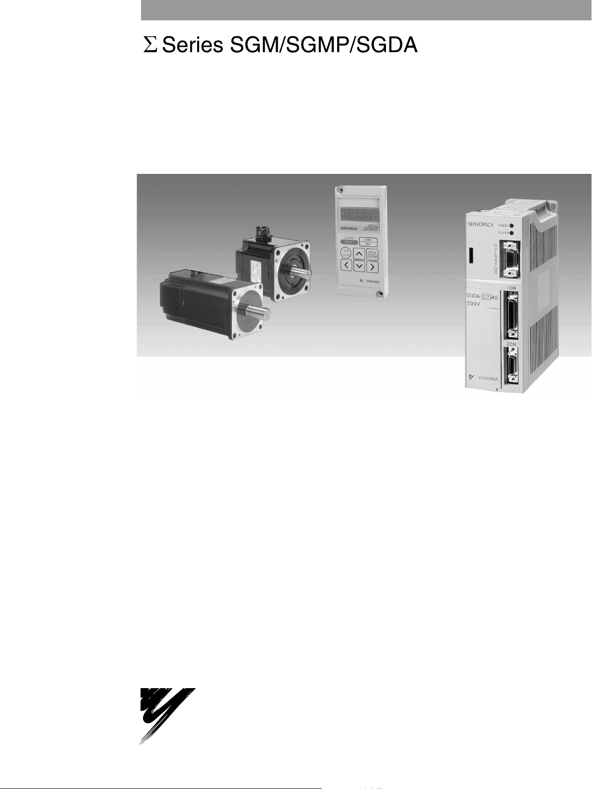
USER'S MANUAL
AC Servomotors and Drivers
SGM/SGMP Servomotors
SGDA Servopack
YASKAWA
YA S K A WA
MANUAL NO. TSE-S800-15C
Page 2

PREFACE
The rapid progress being made in today’s automation and information
technologies is resulting in a growing need for even more-advanced motion
control for future high-tech equipment. The end result is a need for devices
that can provide more-precise and quicker motion at higher speeds. Servo
control technology makes this possible. Launched by Yaskawa in 1993, the
Σ Series consists of innovative AC Servos that were developed using
leading-edge servo control technology.
This manual covers all products in the Σ Series, which feature superior
functions and performance. This manual was designed to provide
comprehensible information for users who are about to use a servo for the
first time as well as for users who already have experience in using servos.
This manual enables users to understand what Σ-Series AC Servos are all
about and how to design, install, operate, and maintain a servo system.
Keep this manual in a convenient location and refer to it whenever
necessary in operating and maintaining the servo system.
YASKAWA ELECTRIC CORPORATION
General Precautions
S Some drawings inthis manual are shown with the protective cover or shields removed, in order to
describe the detail with more clarity. Make sure all covers and shields are replaced before operating this product.
S Some drawings in this manual are shown as typical example and may differ from the shipped
product.
S This manual may be modified when necessary because of improvement of the product, modifica-
tion or changes in specifications.
Such modification is made as a revision by renewing the manual No.
S To order a copy of this manual, if your copy has been damaged or lost, contact your YASKAWA
representative listed on the last page stating the manual No. on the front cover.
S YASKAWA is not responsible for accidents or damages due to any modification of the product
made by the user since that will void our guarantee.
Page 3
NOTES FOR SAFE OPERATION
Read this manual thoroughly before installation, operation, maintenance or inspection of the AC Servo
Drives. In this manual, the NOTES FOR SAFE OPERATION are classified as “WARNING” or
“CAUTION”.
WARNING
Indicates a potentially hazardous situation which, if not avoided, could result in death or serious personal inju-
ry.
CAUTION
Indicates a potentially hazardous situation which, if not avoided, may result in minor or moderate personal
injury and/or damage to the equipment.
In some instances, items described in
follow these important items.
CAUTION
may also result in a serious accident. In either case,
iv
Page 4

WARNING
(WIRING)
S Grounding must be in accordance with the national code and consistent
with sound local practices.
Failure to observe this warning may lead to electric shock or fire.
(OPERATION)
S Never touch any rotating motor parts during operation.
Failure to observe this warning may result in personal injury.
(INSPECTION AND MAINTENANCE)
S Be sure to turn OFF power before inspection or maintenance.
Otherwise, electric shock may result.
S Never open the terminal cover while power is ON, and never turn ON pow-
er when the terminal cover is open.
Otherwise, electric shock may result.
S After turning OFF power, wait at least five minutes before servicing the
product.
Otherwise, residual electric charges may result in electric shock.
CAUTION
(RECEIVING)
S Use the specified combination of SERVOMOTOR and SERVOPACK.
Failure to observe this caution may lead to fire or failure.
(INSTALLATION)
S Never use the equipment where it may be exposed to splashes of water,
corrosive or flammable gases, or near flammable materials.
Failure to observe this caution may lead to electric shock or fire.
(WIRING)
S Do not connect t hree−phase power supply t o output terminals
W
.
Failure to observe this caution may lead to personal injury or fire.
S Securely tighten screws on the power supply and motor output terminals.
Failure to observe this caution can result in a fire.
UV
and
v
Page 5

CAUTION
(OPERATION)
S To avoid inadvertent accidents, run the SERVOMOTOR only in test run
(without load).
Failure to observe this caution may result in personal injury.
S Before starting operation with a load connected, set up user constants
suitable for the machine.
Starting operation without setting up user constants may lead to overrun failure.
S Before starting operation with a load connected, make sure emergency-
stop procedures are in place.
Failure to observe this caution may result in personal injury.
S During operation, do not touch the heat sink.
Failure to observe this caution may result in burns.
(INSPECTION AND MAINTENANCE)
S Do not disassemble the SERVOMOTOR.
Failure to observe this caution may result in electric shock or personal injury.
S Never change wiring while power is ON.
Failure to observe this caution may result in electric shock or personal injury.
vi
Page 6

Manual Contents
This manual provides Σ-Series users with information on the following:
• An overview of servo systems for first-time users.
• Checking the product on delivery and basic applications of the servo.
• Servo applications.
• Selecting an appropriate servo for your needs and placing an order.
• Inspection and maintenance.
Manual Structure
All chapters in this manual are classified into one or more of three areas according to their contents: A, B, and
C. Refer to the applicable chapters for the information you require.
A: Chapters explaining how to select a servo: For users who wish to gain a basic understanding of
Σ Series products or who need to select an appropriate servo.
B: Chapters explaining how to design a servo system: For users who are about to design, install, and
operate a Σ-Series Servo Control System.
C: Chapters explaining maintenance: For users who are going to maintain and troubleshoot Σ-Series
products.
Chapter
CHAPTER 1 For First-time Users of AC Servos 1 A, B....................... .........
CHAPTER 2 Basic Uses of Σ-series Products 15 B........................ .........
CHAPTER 3 Applications of Σ-series Products 51 B....................... .........
CHAPTER 4 Using the Digital Operator 167 B.............................. ........
CHAPTER 5 Servo Selection and Data Sheets 205 A, B........................ ........
CHAPTER 6 Inspection, Maintenance, and Troubleshooting 343 C........... ........
APPENDIXES
Title Page Area
Provides an overview of servos and the Σ Series.
Describes steps to take when product is received, plus basic
wiring and application methods.
Describes the effective usage of Σ-Series features according to
application.
Describes operating procedures for Σ-Series servos, turning
features ON and OFF, setting control constants, etc.
Describes selection methods for Σ-Series servos and peripherals and provides servo specifications.
Describes user maintenance and troubleshooting.
A Differences between SGDA and SGD Servopacks 367 A, B. C........... ........
B Servo Adjustment 374 B, C....................................... ........
C List of I/O Signals 365 A, B, C....................................... ........
D List of User Constants 397 B, C................................... ........
E List of Alarm Displays 409 B, C.................................... ........
INDEX
415 A, B, C.............................................................. ........
vii
Page 7
Basic Terms
Unless otherwise specified, the following definitions are used:
Servomotor: Σ-Series SGM/SGMP Servomotor
Servopack: An amplifier (Trademark of Yaskawa servo amplifier “SGDA Servopack”)
Servodrive: A SGM/SGMP Servomotor and an amplifier (SGDA Servopack)
Servo system: A complete servo control system consisting of servodrive, host controller,
Visual Aids
The following aids are used to indicate certain types of information for easier reference.
.
and peripheral devices
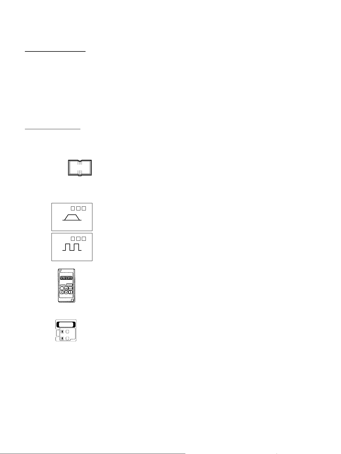
Indicates references for additional information.
TERMS
SGDA- S
Speed/Torque
SGDA- P
Positions
JUSP-OP02A-1
Technical terms placed in bold in the text are briefly explained in a “TERMS” section at the bottom of the page. The following kinds of technical terms are explained:
Technical terms that need to be explained to users who are not very familiar with
servo systems or electronic devices and technical terms specific to Σ Series Ser-
vos that need to be explained in descriptions of functions.
The text indicated by this icon is applicable only to Servopacks for speed/torque
control (Type: SGDAIf neither this icon nor the following icon appears, the description is applicable to
both types of Servopack.
The text indicated by this icon is applicable only to Servopacks for position control
(Type: SGDA-
If neither this icon nor the previous icon appears, the description is applicable to
both types of Servopack.
The text indicated by this icon explains the operating procedure using hand-held
type digital operator (Type: JUSP-OP02A-1).
The text indicated by this icon explains the operating procedure using mount type
digital operator (Type: JUSP-OP03A).
jjj
P).
jjj
S).
viii
JUSP-OP03A
NOTE A Σ-Series Servodrive alone cannot ensure the functionality and performance of the entire
machine control system. It must be combined with an appropriate machine and host controller so that the entire control system works properly. Therefore, carefully read the instruction
manuals for the machine to be used before attempting to operate the servodrive.
Page 8

Yaskawa, 1995
All rights reserved. No part of thispublication may be reproduced, stored in aretrieval system, or transmitted, in any form, or
by any means, mechanical, electronic, photocopying, recording, or otherwise, without the prior written permission of Yaskawa. No patent liability is assumed with respect to the use of the information contained herein. Moreover,because Yaskawa
is constantly striving to improve its high-quality products, the information contained in this manual is subject to change
without notice. Every precaution has been taken in the preparation of this manual. Nevertheless, Yaskawa assumes no responsibility for errors or omissions. Neither is any liability assumed for damages resulting from the use of the information
contained in this publication.
ix
Page 9

CONTENTS
CHAPTER 1 FOR FIRST-TIME USERS OF AC SERVOS 1...............
1.1 Basic Understanding of AC Servos 2..........................................
1.1.1 Servo Mechanisms 2................................................
1.1.2 Servo Configuration 5...............................................
1.1.3 Features of Σ-Series Servos 11.........................................
CHAPTER 2 BASIC USES OF Σ-SERIES PRODUCTS 15.................
2.1 Precautions 16.............................................................
2.1.1 Notes on Use 16....................................................
2.2 Installation 18.............................................................
2.2.1 Checking on Delivery 18..............................................
2.2.2 Installing the Servomotor 19...........................................
2.2.3 Installing the Servopack 22............................................
2.3 Connection and Wiring 25....................................................
2.3.1 Connecting to Peripheral Devices 25....................................
2.3.2 Main Circuit Wiring and Power ON Sequence 2 8..........................
2.3.3 Examples of Connecting I/O Signal Terminals 30..........................
2.4 Conducting a Test Run 37....................................................
2.4.1 Test Run in Two Steps 37.............................................
2.4.2 Step 1: Conducting a Test Run for Motor without Load 39...................
2.4.3 Step 2: Conducting a Test Run with the Motor Connected to the Machine 44.....
2.4.4 Supplementary Information on Test Run 46...............................
2.4.5 Minimum User Constants Required and Input Signals 48....................
CHAPTER 3 APPLICATIONS OF Σ-SERIES PRODUCTS 51..............
3.1 Setting User Constants According to Machine Characteristics 54.....................
3.1.1 Changing the Direction of Motor Rotation 54.............................
3.1.2 Setting the Overtravel Limit Function 56.................................
3.1.3 Restricting Torque 59................................................
3.2 Setting User Constants According to Host Controller 65............................
3.2.1 Inputting Speed Reference 65..........................................
3.2.2 Inputting Position Reference 69........................................
3.2.3 Using Encoder Output 73.............................................
3.2.4 Using Contact I/O Signals 77..........................................
3.2.5 Using Electronic Gear 79.............................................
3.2.6 Using Contact Input Speed Control 83...................................
3.2.7 Using Torque Control 88..............................................
3.2.8 Using Torque Feed-forward Function 94.................................
3.2.9 Using Torque Restriction by Analog Voltage Reference 95...................
3.2.10 Using the Reference Pulse Inhibit Function (INHIBIT) 97...................
3.2.11 Using the Reference Pulse Input Filter Selection Function 99.................
3.3 Setting Up the Σ Servopack 100................................................
3.3.1 Setting User Constants 100.............................................
3.3.2 Setting the Jog Speed 101..............................................
3.3.3 Setting the Number of Encoder Pulses 102.................................
3.3.4 Setting the Motor Type 103.............................................
x
Page 10

CONTENTS
3.4 Setting Stop Mode 104.......................................................
3.4.1 Adjusting Offset 104..................................................
3.4.2 Using Dynamic Brake 105.............................................
3.4.3 Using Zero-Clamp 106................................................
3.4.4 Using Holding Brake 107..............................................
3.5 Running the Motor Smoothly 111...............................................
3.5.1 Using the Soft Start Function 111........................................
3.5.2 Using the Smoothing Function 112.......................................
3.5.3 Adjusting Gain 112...................................................
3.5.4 Adjusting Offset 113..................................................
3.5.5 Setting the Torque Reference Filter Time Constant 113.......................
3.6 Minimizing Positioning Time 114...............................................
3.6.1 Using Autotuning Function 114.........................................
3.6.2 Setting Servo Gain 114................................................
3.6.3 Using Feed-forward Control 116........................................
3.6.4 Using Proportional Control 116.........................................
3.6.5 Setting Speed Bias 117................................................
3.6.6 Using Mode Switch 118...............................................
3.6.7 Using Speed Loop Compensation Function 124.............................
3.7 Forming a Protective Sequence 125.............................................
3.7.1 Using Servo Alarm Output and Alarm Code Output 125......................
3.7.2 Using Servo ON Input Signal 125........................................
3.7.3 Using Positioning Complete Signal 129...................................
3.7.4 Using Speed Coincidence Output Signal 131...............................
3.7.5 Using Running Output Signal 132.......................................
3.7.6 Handling of Power Loss 134............................................
3.8 Special Wiring 136..........................................................
3.8.1 Wiring Instructions 136................................................
3.8.2 Wiring for Noise Control 138...........................................
3.8.3 Using More Than One Servo Drive 143...................................
3.8.4 Using Regenerative Units 144...........................................
3.8.5 Using an Absolute Encoder 148.........................................
3.8.6 Extending an Encoder Cable 157........................................
3.8.7 Using SGDA Servopack with High Voltage Line 159........................
3.8.8 Connector Terminal Layouts 161........................................
CHAPTER 4 USING THE DIGITAL OPERATOR 167.....................
4.1 Basic Operations 168.........................................................
4.1.1 Connecting the Digital Operator 168.....................................
4.1.2 Resetting Servo Alarms 169............................................
4.1.3 Basic Functions and Mode Selection 170..................................
4.1.4 Operation in Status Display Mode 171....................................
4.1.5 Operation in User Constant Setting Mode 174..............................
4.1.6 Operation in Monitor Mode 179.........................................
xi
Page 11

CONTENTS
4.2 Using the Functions 183......................................................
4.2.1 Operation in Alarm Trace-back Mode 183.................................
4.2.2 Operation Using the Digital Operator 186.................................
4.2.3 Autotuning 189......................................................
4.2.4 Reference Offset Automatic Adjustment 196...............................
4.2.5 Speed Reference Offset Manual Adjustment Mode 174.......................
4.2.6 Clearing Alarm Trace-back Data 202.....................................
4.2.7 Checking Motor Type 203..............................................
4.2.8 Checking Software Version 204.........................................
CHAPTER 5 SERVO SELECTION AND DATA SHEETS 205...............
5.1 Selecting a Σ-Series Servo 207.................................................
5.1.1 Selecting a Servomotor 207............................................
5.1.2 Selecting a Servopack 213.............................................
5.1.3 Selecting a Digital Operator 215.........................................
5.2 SGM Servomotor 217........................................................
5.2.1 Ratings and Specifications 217..........................................
5.2.2 Mechanical Characteristics 232..........................................
5.3 Servopack Ratings and Specifications 235........................................
5.3.1 Ratings and Specifications 235..........................................
5.3.2 Overload Characteristics 240...........................................
5.3.3 Starting Time and Stopping Time 241.....................................
5.3.4 Load Inertia 241.....................................................
5.3.5 Overhanging Loads 244...............................................
5.3.6 In-rush Current and Power Loss 245......................................
5.4 Σ-Series Dimensional Drawings 246.............................................
5.4.1 Servomotor Dimensional Drawings 246...................................
5.4.2 Servopack Dimensional Drawings 289....................................
5.4.3 Digital Operator Dimensional Drawings 291...............................
5.5 Selecting Peripheral Devices 293...............................................
5.5.1 Selecting Peripheral Devices 293........................................
5.5.2 Order List 299.......................................................
5.6 Specifications and Dimensional Drawings of Peripheral Devices 308...................
5.6.1 Cable Specifications and Peripheral Devices 308............................
5.6.2 Motor Cables 311....................................................
5.6.3 Connector Kits 314...................................................
5.6.4 Brake Power Supply 318...............................................
5.6.5 Encoder Cables 320...................................................
5.6.6 Battery for Absolute Encoder 325........................................
5.6.7 1CN Connector 326...................................................
5.6.8 Connector Terminal Block Converter Unit 328.............................
5.6.9 Cable With 1CN Connector and One End Without Connector 330..............
5.6.10 Circuit Breaker 330...................................................
5.6.11 Noise Filter 331......................................................
5.6.12 Magnetic Contactor 332...............................................
5.6.13 Surge Suppressor 333.................................................
5.6.14 Regenerative Unit 334.................................................
xii
Page 12

CONTENTS
5.6.15 Variable Resistor for Speed Setting 335...................................
5.6.16 Encoder Signal Converter Unit 336......................................
5.6.17 Cables for Connecting PC and Servopack 338..............................
CHAPTER 6 INSPECTION, MAINTENANCE, AND TROUBLESHOOTING 343
6.1 Inspection and Maintenance 344................................................
6.1.1 Servomotor 344......................................................
6.1.2 Servopack 345.......................................................
6.1.3 Replacing Battery for Absolute Encoder 346...............................
6.2 Troubleshooting 347.........................................................
6.2.1 Troubleshooting Problems with Alarm Display 347..........................
6.2.2 Troubleshooting Problems With No Alarm Display 366......................
6.2.3 Internal Connection Diagram and Instrument Connection Examples 368.........
APPENDIXES
A Differences Between SGDA and SGD Servopacks 367..............................
B Servo Adjustment 374........................................................
B.1 Σ-Series AC Servopack Gain Adjustment 374.....................................
B.1.1 Σ-Series AC Servopacks and Gain Adjustment Methods 374..................
B.1.2 Basic Rules for Gain Adjustment 375.....................................
B.2 Adjusting a Speed-control Servopack 376........................................
B.2.1 Adjusting Using Auto-tuning 376........................................
B.2.2 Manual Adjustment 377...............................................
B.3 Adjusting a Position-control Servopack 380.......................................
B.3.1 Adjusting Using Auto-tuning 380........................................
B.3.2 Manual Adjustment 381...............................................
B.4 Gain Setting References 385...................................................
B.4.1 Guidelines for Gain Settings According to Load Inertia Ratio 385..............
C List of I/O Signals 385........................................................
D List of User Constants 397....................................................
E List of Alarm Displays 409....................................................
INDEX 415...........................................................
xiii
Page 13

FOR FIRST-TIME USERS OF AC SERVOS
1
1
This chapter is intended for first-time users of AC servos. It describes the basic configuration of a servo mechanism and basic technical terms relating to
servos.
Users who already have experience in using a servo should also take a look at
this chapter to understand the features of Σ-Series AC Servos.
1.1 Basic Understanding of AC Servos 2...........
1.1.1 Servo Mechanisms 2..................................
1.1.2 Servo Configuration 5.................................
1.1.3 Features of Σ-Series Servos 11...........................
1
Page 14

1
FOR FIRST−TIME USERS OF AC SERVOS
1.1.1 Servo Mechanisms
1.1 Basic Understanding of AC Servos
This section describes the basic configuration of a servo mechanism and technical terms
relating to servos and also explains the features of Σ-Series AC Servos.
1.1.1 Servo Mechanisms 2..............................................
1.1.2 Servo Configuration 5..............................................
1.1.3 Features of Σ-Series Servos 11......................................
1.1.1 Servo Mechanisms
You may be familiar with the following terms:
• Servo
• Servo mechanism
• Servo control system
In fact, these terms are synonymous. They have the following meaning:
A control mechanism that monitors physical quantities such as specified positions.
In short, a servo mechanism is like a servant who does tasks faithfully and quickly according
to his master’s instructions. In fact, “servo” originally derives from the word “servant.”
TERMS
Servo mechanism
According to Japanese Industrial Standard (JIS) terminology, a “servo mechanism” is defined as a mechanism that uses the position, direction, or orientation of an object as a process variable to control a system to follow any changes in a target value (set point).
More simply, a servo mechanism is a control mechanism that monitors physical quantities
such as specified positions. Feedback control is normally performed by a servo mechanism. (Source: JIS B0181)
2
Page 15
1.1 Basic Understanding of AC Servos
Servo system could be defined in more detail as a mechanism that:
• Moves at a specified speed and
• Locates an object in a specified position
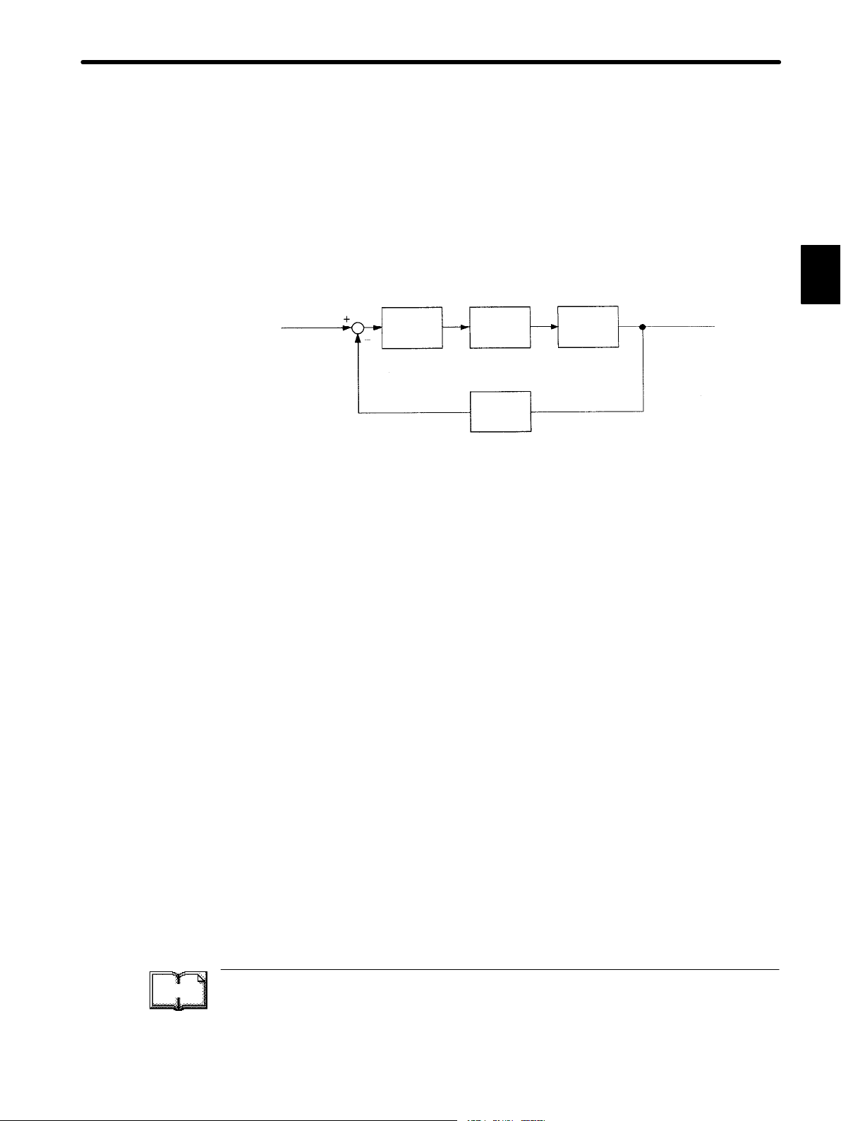
To develop such a servo system, an automatic control system involving feedback control
must be designed. This automatic control system can be illustrated in the following block diagram:
Configuration of Servo System
Specified position
input
Servo
amplifier
Servo
motor
Feedback part
Detector
Controlled
machine
(load)
Machine position
output
This servo system is an automatic control system that detects the machine position (output
data), feeds back the data to the input side, compares it with the specified position (input
data), and moves the machine by the difference between the compared data.
In other words, the servo system is a control system that forces the output data to
match the specified input data.
If, for example, the specified position changes, the servo system will reflect the changes.
In the above example, input data is defined as a position, but input data can be any physical
quantities such as orientation (angle), water pressure, or voltage.
1
TERMS
Position, speed, force (torque), electric current, and so on are typical controlled values for a
servo system.
The main technical terms used in this manual are as follows:
1) Servo mechanism
2) Servo
Normally, servo is synonymous with servo mechanism. However, because “mechanism” is
omitted, the meaning becomes somewhat ambiguous. Servo may refer to the entire servo
mechanism but may also refer to an integral part of a servo mechanism such as a servomotor
or a servo amplifier. This manual also follows this convention in the use of the term “servo”.
Feedback control
A control that returns process variables to the input side and forms a closed loop. It is also
called closed-loop control.
3
Page 16
1
FOR FIRST−TIME USERS OF AC SERVOS
1.1.1 Servo Mechanisms
cont.
3) Servo control system
Servo control system is almost synonymous with servo mechanism but places the focus on
system control. In this manual, the term “servo system” is also used as a synonym of servo
control system.
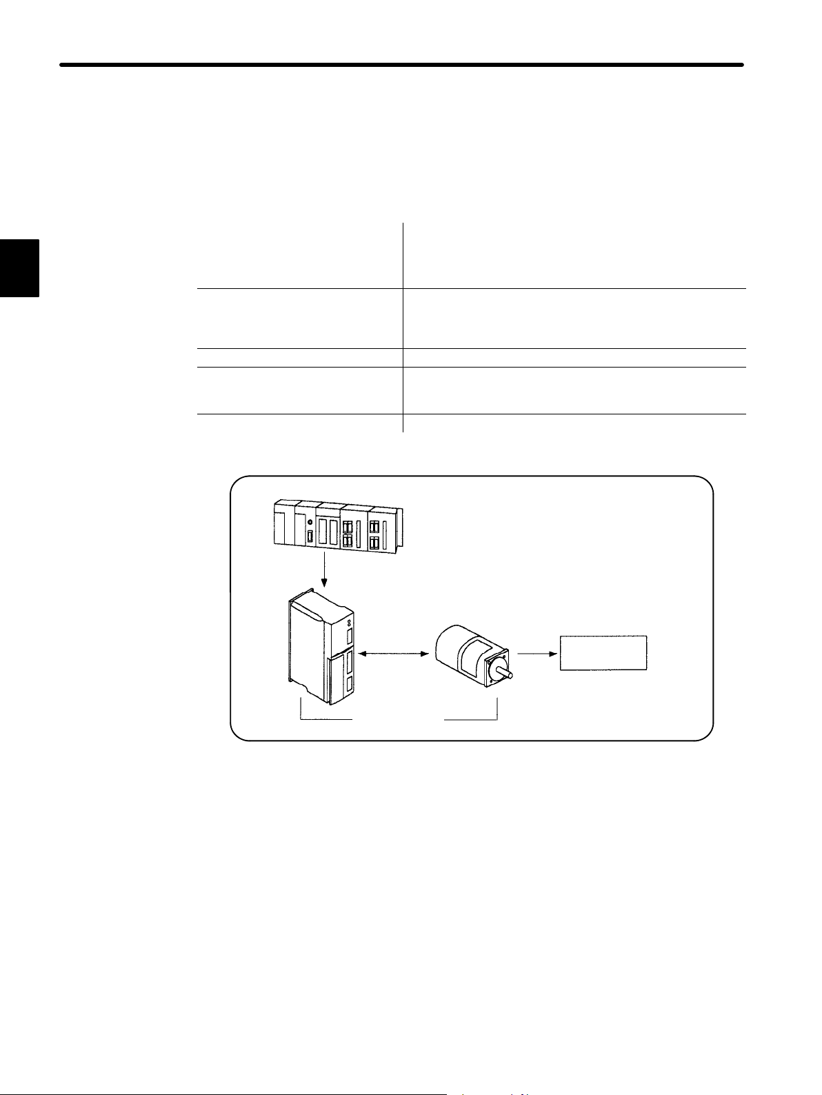
Related Terms Meaning
Servomotor General servomotors or Yaskawa SGM/SGMP
Servopack Trademark of Yaskawa servo amplifier “SGDA Servopack.”
Servo drive A Servomotor and amplifier pair. Also called “servo.”
Servo system A closed control system consisting of a host controller,
Servomotors. In some cases, a position detector (encoder)
is included in a servomotor.
Servopack is divided into two types: SGDA-jjjS (for
speed/torque control) and SGDA-jjjP (for position
control).
servo drive and controlled system to form a servo
mechanism.
Host controller
Reference
Amplifier
(Servopack)
Servo drive
Servomotor
Servo system
Operate
Controlled
system
4
Page 17
1.1.2 Servo Configuration
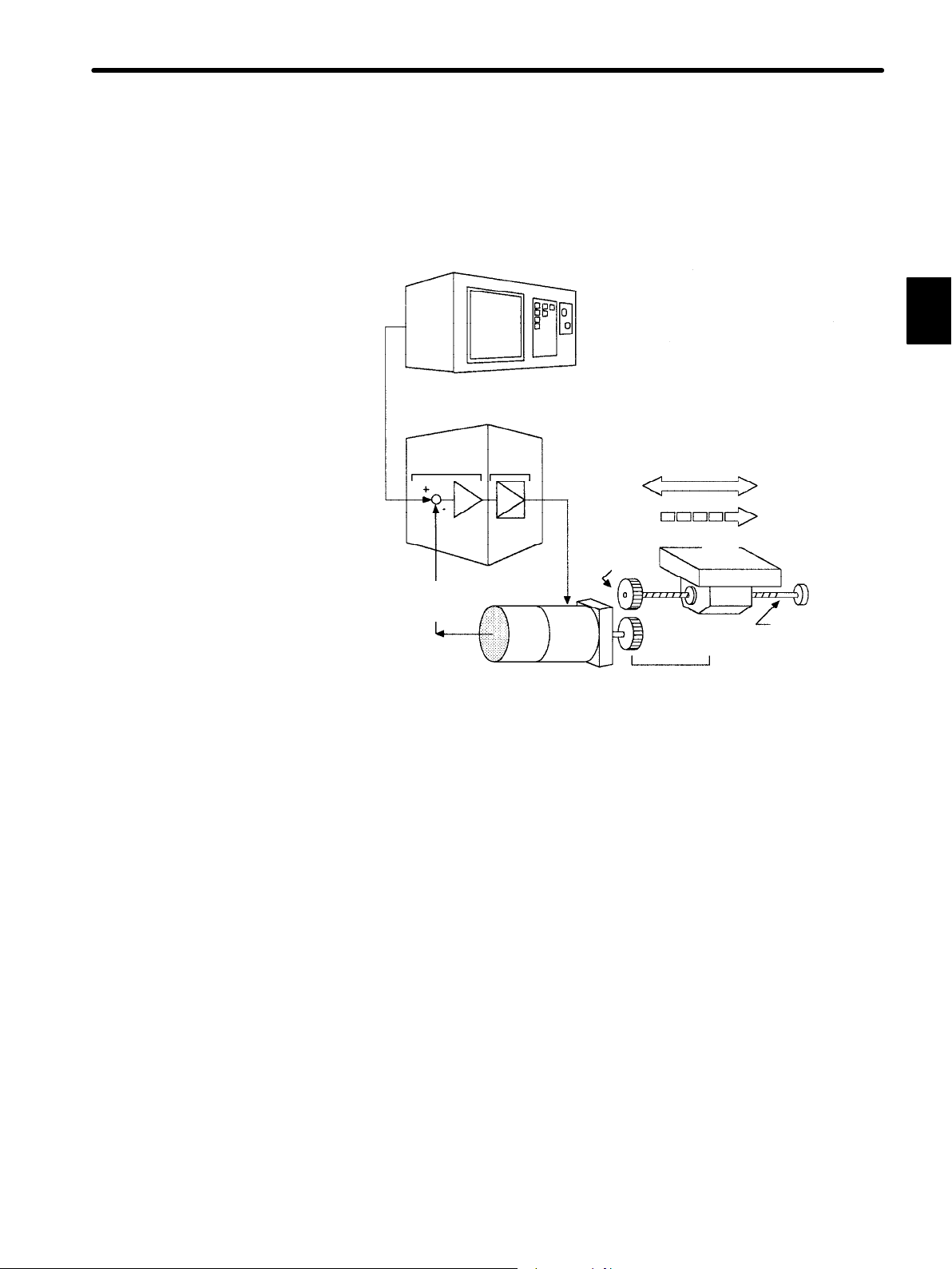
1) Configuration of Servo System
The following diagram illustrates a servo system in detail:
1.1 Basic Understanding of AC Servos
Host controller
(5)
Position or
speed
reference
Servo amplifier
Comparator
(Input)
Position or
speed
feedback
Power
amplifier
Detector
(1) Controlled system: Mechanical system for which the position or speed is to be con-
trolled.
This includes a drive system that transmits torque from a servomotor.
(4)
Motor
drive
circuit
Gear
(2)
(3)
Servomotor Drive system
(Output)
(1)
Controlled
system
Position
Speed
Movable
table
Ball screw
1
(2) Servomotor: A main actuator that moves a controlled system. Two types are
available: AC servomotor and DC servomotor.
(3) Detector: A position or speed detector. Normally, an encoder mounted on
a motor is used as a position detector.
(4) Servo amplifier: An amplifier that processes an error signal to correct the differ-
ence between a reference and feedback data and operates the
servomotor accordingly. A servo amplifier consists of a
comparator, which processes error signals, and a power amplifier, which operates the servomotor.
(5) Host controller: A device that controls a servo amplifier by specifying a position
or speed as a set point.
5
Page 18
FOR FIRST−TIME USERS OF AC SERVOS
1.1.2 Servo Configuration
cont.
Servo components (1) to (5) are outlined below:
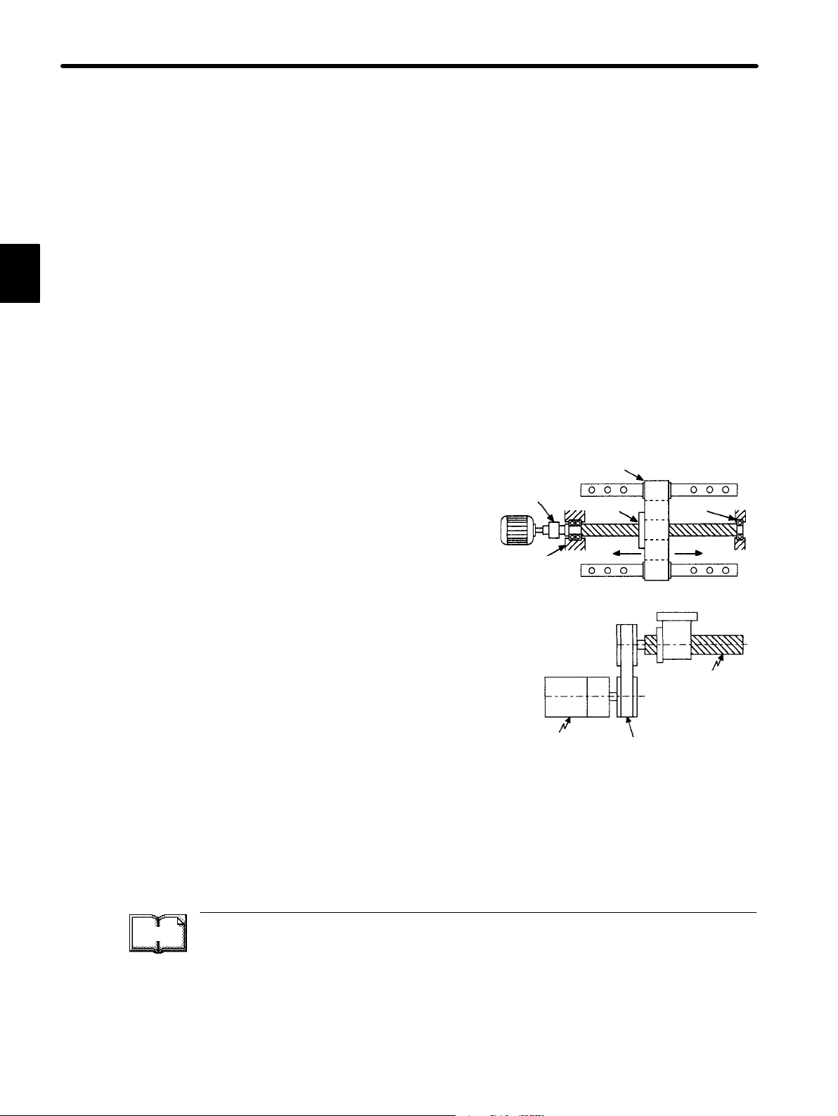
(1) Controlled system
In the previous figure, the controlled system is a movable table for which the position
or speed is controlled. The movable table is driven by a ball screw and is connected to
the servomotor via gears.
So, the drive system consists of:
1
Gears + Ball Screw
This drive system is most commonly used because the power transmission ratio
(gear ratio) can be freely set to ensure high positioning accuracy. However, play in the
gears must be minimized.
The following drive system is also possible when the controlled system is a movable
table:
Coupling + Ball Screw
When the power transmission ratio is 1 :
1, a coupling is useful because it has no
play.
Coupling
Rolling-contact
guide
Ball screw
Rolling-contact
bearing
This drive system is widely used for machining tools.
Housing
Timing Belt + Trapezoidal Screw Thread
A timing belt is a coupling device that allows
the power transmission ratio to be set freely
and that has no play.
A trapezoidal screw thread does not provide
excellent positioning accuracy, so can be
Trapezoidal
screw
thread
treated as a minor coupling device.
Servomotor
Timing belt
To develop an excellent servo system, it is important to select a rigid drive system that
has no play.
Configure the controlled system by using an appropriate drive system for the control
purpose.
TERMS
Drive system
Also called a drive mechanism.
A drive system connects an actuator (such as a servomotor) to a controlled system and
serves as a mechanical control component that transmits torque to the controlled system,
orientates the controlled system, and converts motion from rotation to linear motion and
vice versa.
6
Page 19

(2) Servomotor
(a) DC Servomotor and AC Servomotor
Servomotors are divided into two types: DC servomotors and AC servomotors.
DC servomotors are driven by direct current (DC). They have a long history. Up
until the 1980s, the term “servomotor” used to imply a DC servomotor.
1.1 Basic Understanding of AC Servos
From 1984, AC servomotors were emerging as a result of rapid progress in microprocessor technology. Driven by alternating current (AC), AC servomotors are
now widely used because of the following advantages:
• Easy maintenance: No brush
• High speed: No limitation in rectification rate
Note however that servomotors and Servopacks use some parts that are subject
to mechanical wear or aging. For preventive maintenance, inspect and replace
parts at regular intervals.
For details, refer to Chapter 6 Inspection, Maintenance, and Troubleshooting.
(b) AC Servomotor
AC servomotors are divided into two types: synchronous type and induction type.
The synchronous type is more commonly used.
For a synchronous type servomotor, motor speed is controlled by changing the
frequency of alternating current.
A synchronous type servomotor provides strong holding torque when stopped, so
this type is ideal when precise positioning is required. Use this type for a servo
mechanism for position control.
1
The following figure illustrates the structure of a synchronous type servomotor:
Rotary disc
Light-emitting
element
Position detector
(encoder)
Light-receiving
element
Armature
wire
Lead wire
Housing
Stator core
Magnet
Front cap
Ball bearing
Shaft
Rotor core
Yaskawa SGM and SGMP Servomotors are of the synchronous type.
7
Page 20
FOR FIRST−TIME USERS OF AC SERVOS
1.1.2 Servo Configuration
cont.
(c) Performance of Servomotor
A servomotor must have “instantaneous power” so that it can start as soon as a
start reference is received.
The term “power rating (kW/s)” is used to represent instantaneous power.
It refers to the electric power (kW) that a servomotor generates per second.
The greater the power rating, the more powerful the servomotor.
1
(3) Detector
A servo system requires a position or speed detector. It uses an encoder mounted on
a servomotor for this purpose.
Encoders are divided into the following two types:
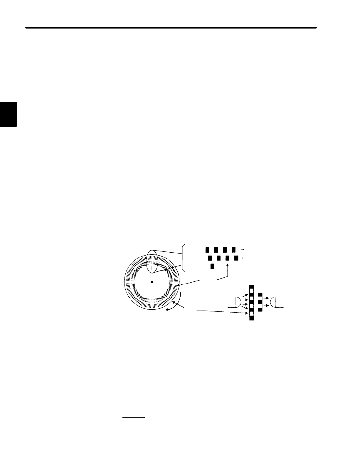
(a) Incremental Encoder
An incremental encoder is a pulse generator, which generates a certain number
of pulses per revolution (e.g., 2,000 pulses per revolution). If this encoder is connected to the mechanical system and one pulse is defined as a certain length
(e.g., 0.001 mm), it can be used as a position detector.
However,this encoder does not detect an absolute position and merely outputs a
pulse train. Hence zero return operation must be performed before positioning.
The following figure illustrates the operation principle of a pulse generator:
Phase A pulse train
Phase B pulse train
Fixed slit
Light-receiving
element
Rotary slit
Center of
revolution
Phase A
Phase B
Phase Z
Rotary
disc
Slit
Light-emitting
element
(b) Absolute Encoder
An absolute encoder is designed to detect an absolute angle of rotation as well as
to perform the general functions of an incremental encoder. With an absolute encoder,therefore, it is possible to create a system that does not require zero return
operation at the beginning of each operation.
• Difference between an absolute
An absolute
encoder will keep track of the motor shaft position even if system
and incremental encoder:
power is lost and some motion occurs during that period of time. The incremental
encoder is incapable of the above.
8
Page 21
1.1 Basic Understanding of AC Servos
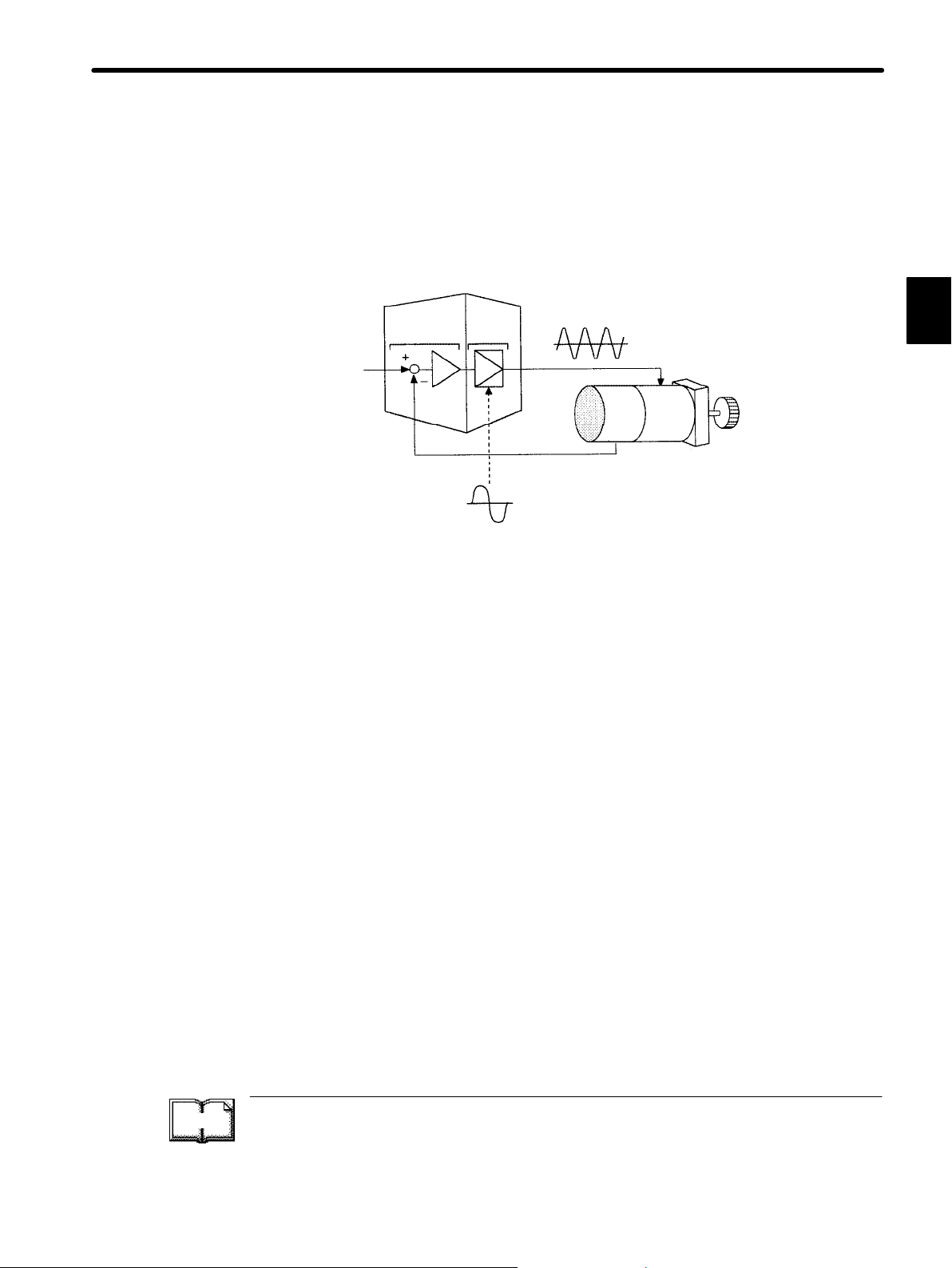
(4) Servo amplifier
A servo amplifier is required to operate an AC servomotor.
The following figure illustrates the configuration of a servo amplifier:
Servo amplifier
Motor driving AC power
Servomotor
Commercial AC power
Reference
input
Comparator
Feedback
Power
amplifier
A servo amplifier consists of the following two sections:
(a) Comparator
A comparator consists of a comparison function and a control function. The comparison function compares reference input (position or speed) with a feedback
signal and generates a differential signal.
1
TERMS
The control function amplifies and transforms the differential signal. In other
words, it performs proportional (P) control or proportional/integral (PI) control.
(It is not important if you do not understand these control terms completely at this
point.)
(b) Power Amplifier
A power amplifier runs the servomotor at a speed or torque proportional to the
output of the comparator. In other words, from the commercial power supply of
50/60 Hz, it generates alternating current with a frequency proportional to the reference speed and runs the servomotor with this current.
Proportional/integral (PI) control
PI control provides more accurate position or speed control than proportional control, which
is more commonly used.
9
Page 22

1
FOR FIRST−TIME USERS OF AC SERVOS
1.1.2 Servo Configuration
cont.
(5) Host Controller
A host controller controls a servo amplifier by specifying a position or speed as a set
point.
For speed reference, a position control loop may be formed in the host controller when
a position feedback signal is received. Yaskawa PROGIC-8 is a typical host controller.
10
TERMS
PROGIC-8
A programmable machine controller. If combined with a
servo amplifier for speed control (maximum eight axis
control), the PROGIC-8 can provide position control.
The PROGIC-8 also provides programmable controller
functions.
Page 23
1.1.3 Features of Σ-Series Servos
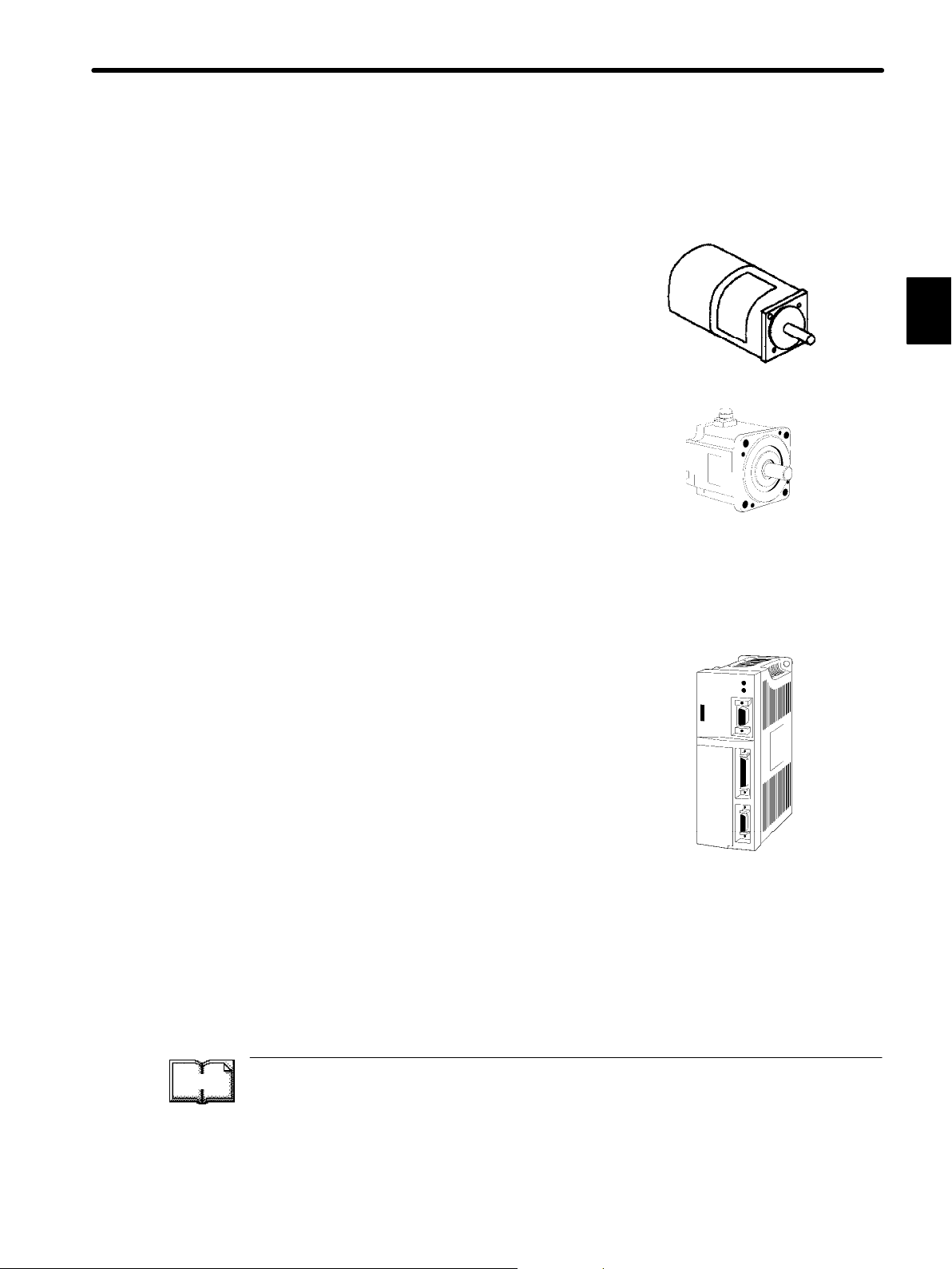
1) Σ-Series SGM/SGMP Servomotors are synchronous type servomotors and have the following features:
• Size and weight reduced to one-third those of
our conventional models.
Compact Servomotor for saving installation
space.
• Servo performance (power rating) enhanced to
three times that of our conventional models.
Enhanced power rating (kW/s) to satisfy every
need.
• A wide product range covering rated output of
30 W to 750 W.
1.1 Basic Understanding of AC Servos
1
SGM type
Supply Voltage Rated Output
100 VAC: 30 W, 50 W, 100 W, 200 W, 300 W
(0.04 HP, 0.07 HP, 0.13 HP, 0.27 HP, 0.40 HP)
200 VAC: 30 W, 50 W, 100 W, 200 W, 400 W, 750 W
(0.04 HP, 0.07 HP, 0.13 HP, 0.27 HP, 0.53 HP, 1.01 HP)
2) SGDA Servopacks are divided into the following
two types according to usage:
• For Speed/Torque Control: SGDA-jjjS Type
This type uses speed or torque reference input.
Reference input is by analog voltage.
• For Position Control: SGDA-jjjP Type
This type uses position reference input. Reference
input is by pulse train.
SGMP type
TERMS
Power rating (kW/s)
A constant that represents response performance of a servomotor. It can be determined by
dividing squared rated torque by motor inertia. Power rating is the electric power (kW) that a
servomotor can generate per second.
The greater the power rating, the more powerful the servomotor.
11
Page 24
1
FOR FIRST−TIME USERS OF AC SERVOS
1.1.3 Features of Σ-Series Servos cont.
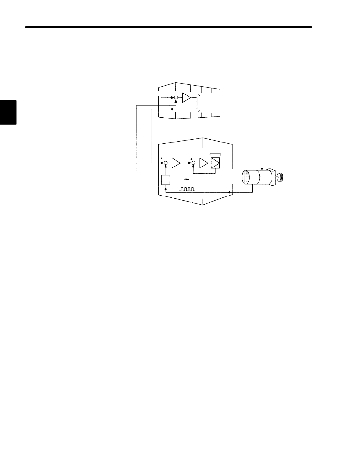
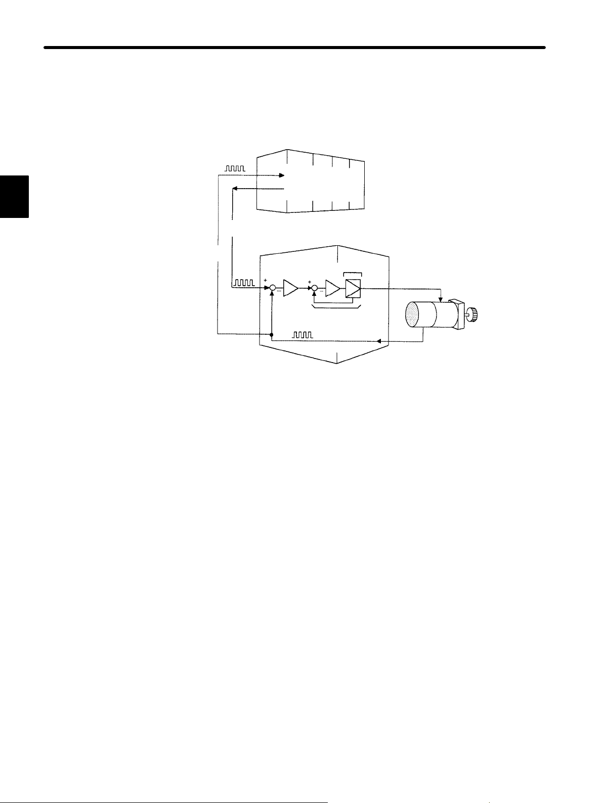
3) The most common usage of a Servopack for speed/torque control is shown below:
• Using Servopack for Speed/Torque Control (Speed Control)
Position reference +
Position
feedback
(Analog
voltage)
Speed
reference
Position
Host controller
Position control loop
Servopack for
speed/torque control
Speed
Convert
Pulse train
Position feedback
Power
amplifier
Servomotor
Torque
(current)
feedback
Encoder
As shown in the figure above, a position control loop is formed in the host controller. The
host controller compares a position reference with a position feedback signal and sends
processing results to the Servopack as a speed reference.
In this way, the host controller can freely perform the control required for the servo mechanism.
The Servopack undertakes the speed control loop and subsequent control processing.
Yaskawa programmable machine controller PROGIC-8 is available as a typical host controller.
12
Page 25
1.1 Basic Understanding of AC Servos
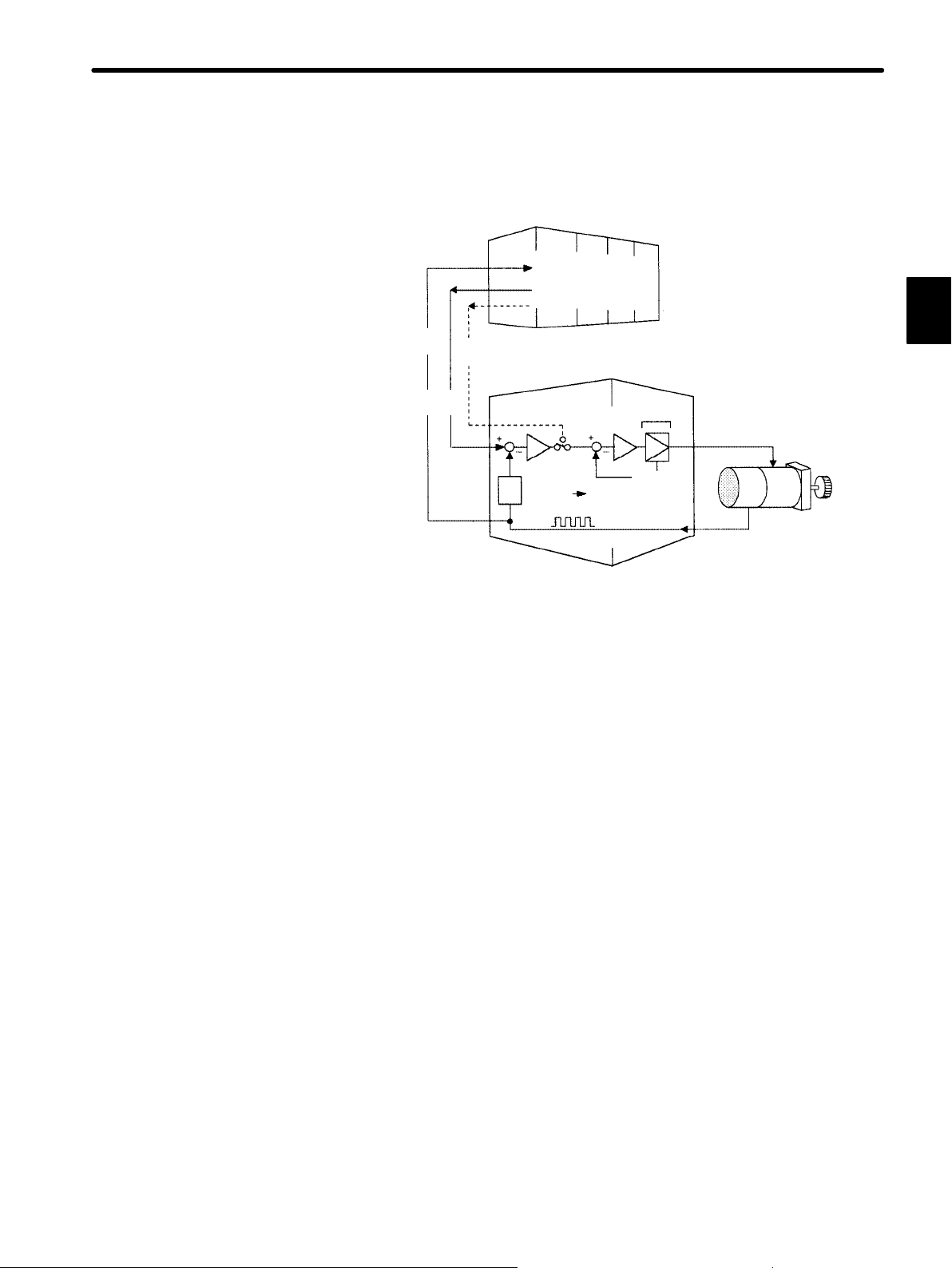
4) Servopack for speed/torque control can also provide torque control as shown below.
• Using Servopack for Speed/Torque Control (Torque Control)
Host controller
Position
monitoring
Position
information
Speed
reference
Torque
reference
(Analog
voltage)
(Analog voltage)
Position
Convert
Position feedback Encoder
Servopack for
speed/torque
control
Speed
Pulse train
Power
amplifier
Torque
(current)
feedback
Servomotor
1
Set the user constants for Servopack to switch between the following torque control
modes:
(1) Controlling servomotor torque by torque reference
(Torque control I)
(2) Operating servomotor by switching between torque reference and speed refer-
ence
(Torque control II)
The host controller outputs a torque reference or speed reference to control the Servopack.
It also receives a pulse train (position information) from the Servopack and uses it to monitor the position.
13
Page 26
1
FOR FIRST−TIME USERS OF AC SERVOS
1.1.3 Features of Σ-Series Servos cont.
5) Servopack for position control can be used as below.
• Using Servopack for Position Control
Position
reference
Position
information
Pulse
train
Host controller
Position
monitoring
Speed/current loop
Pulse train
Position feedback
Servopack for
position control
Power
amplifier
Servomotor
Encoder
The host controller can send a position reference (pulse train) to the Servopack to perform positioning or interpolation.
This type of Servopack contains a position control loop.
User constants can be used to select either of the following pulse trains:
(1) Code and pulse train
(2) Two-phase pulse train with 90° phase difference
(3) Forward and reverse pulse trains
The host controller receives a pulse train (position information) from the Servopack and
uses it to monitor the position.
6) A Digital Operator can be used to set user constants for a Servopack as follows:
(1) Setting user constants to enable or disable each function
14
(2) Setting user constants required for functions to be used
Set user constants according to the servo system to be set up.
Page 27

BASIC USES OF Σ-SERIES
PRODUCTS
This chapter describes the first things to do when Σ-Series products are delivered. It also explains the most fundamental ways of connecting and operating
Σ-Series products. Both first-time and experienced servo users
this chapter.
2.1 Precautions 16...............................
2.2 Installation 18...............................
2.1.1 Notes on Use 16.......................................
2.2.1 Checking on Delivery 18................................
2.2.2 Installing the Servomotor 19.............................
2.2.3 Installing the Servopack 22..............................
2
must read
2
2.3 Connection and Wiring 25.....................
2.3.1 Connecting to Peripheral Devices 25......................
2.3.2 Main Circuit Wiring and Power ON Sequence 28............
2.3.3 Examples of Connecting I/O Signal Terminals 30............
2.4 Conducting a Test Run 37.....................
2.4.1 Test Run in Two Steps 37...............................
2.4.2 Step 1: Conducting a Test Run for Motor without Load 39.....
2.4.3 Step 2: Conducting a Test Run with the Motor Connected
to the Machine 44.....................................
2.4.4 Supplementary Information on Test Run 46.................
2.4.5 Minimum User Constants Required and Input Signals 48......
15
Page 28
BASIC USES OF Σ-SERIES PRODUCTS
2.1.1 Notes on Use
2.1 Precautions
This section provides notes on using Σ-Series products.
2.1.1 Notes on Use 16...................................................
2.1.1 Notes on Use
NOTE Always note the following to ensure safe use.
2
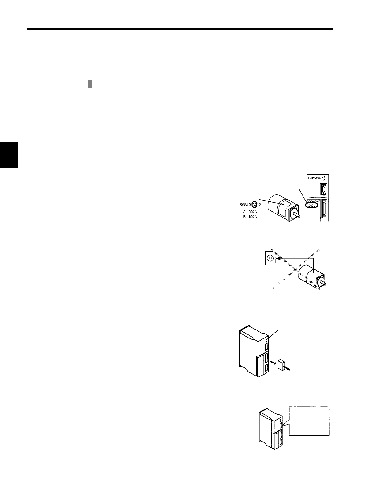
Two types of supply voltage are available, 100 V and 200 V.
Both Σ-Series Servomotor and Servopack have
100 V and 200 V types. Be sure to use the correct
type.
Type NP
Always use the SGM Servomotor and SGDA Servopack in pairs.
The SGM Servomotor cannot run without the
SGDA Servopack.
Do not plug the SGM Servomotor directly into the
commercial power supply. (Direct connection to
the commercial power supply will damage the
Servomotor.)
200 V or
100 V power
supply
Do not change wiring when power is ON.
Always turn the power OFF before connecting or
disconnecting a connector.
(Except for Digital Operator (Types: JUSPOP02A-1, JUSP-OP03A))
Voltage
label
Direct
connection
Damage will result!
Extinguished
Always turn the
power OFF
before
connecting or
disconnecting a
connector.
16
Note that residual voltage still remains in the Servopack even after the power is
turned OFF.
Even after the power is turned OFF, residual voltage still remains in the capacitor inside the Servopack. If inspection is to be performed after the
power is turned OFF, always wait at least 5 min-
Careful!
Residual
voltage remains
in capacitor
utes to avoid the risk of an electrical shock.
Wait at least 5
minutes
Page 29
2.1 Precautions
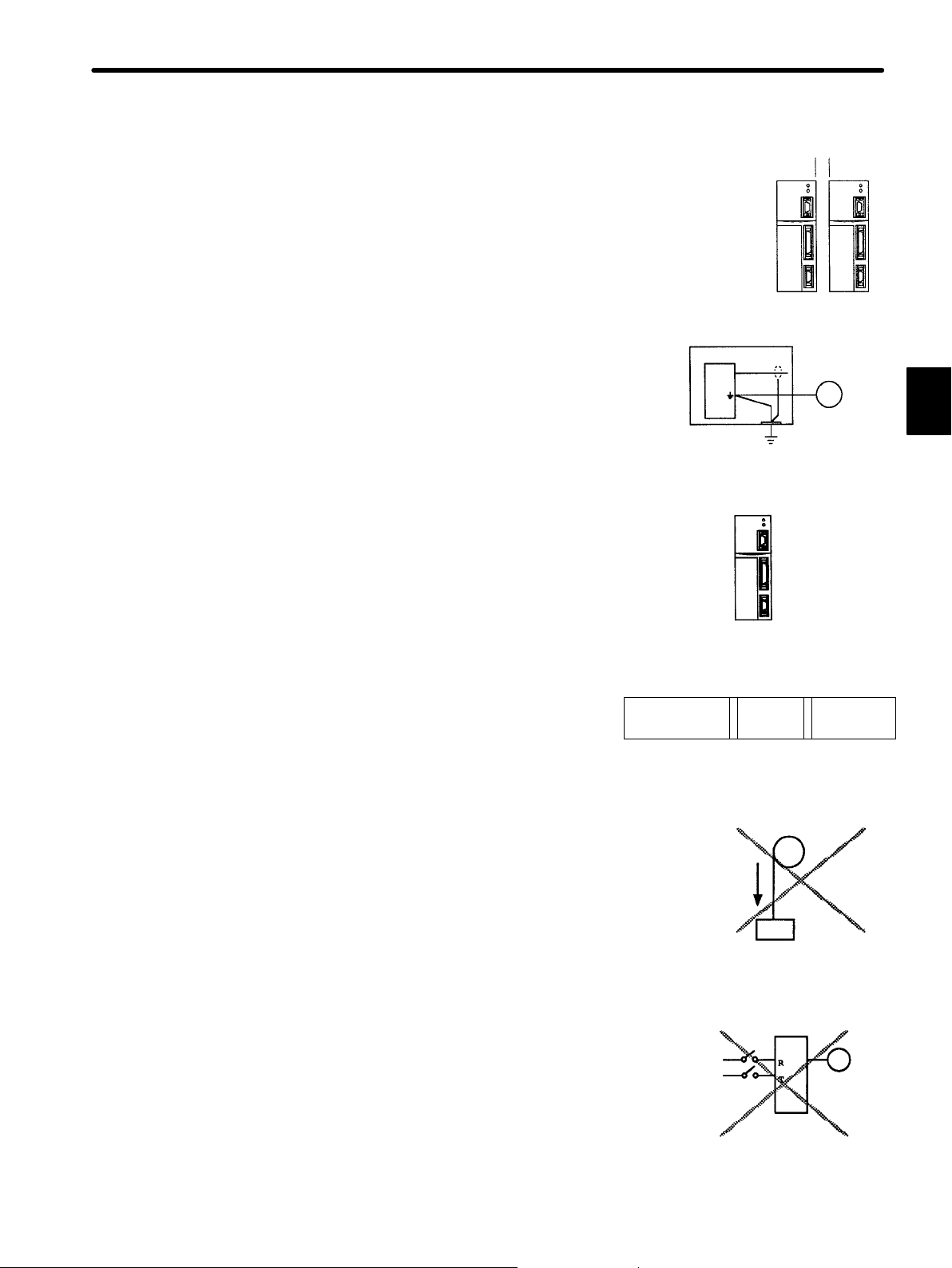
Always follow the specified installation method.
Provide sufficient clearance
The Servopack generates heat. Install the Servopack so that it can radiate heat freely. Note also
that the Servopack must be in an environment
free from condensation, vibration and shock.
Ambient
temperature:
0to55°C
Perform noise reduction and grounding properly.
If the signal line is noisy, vibration or malfunction
will result.
D Separate high-voltage cables from low-voltage cables.
D Use cables as short as possible.
D Use at least class 3 grounding (ground resistance
100Ω or below) for the Servomotor and Servopack.
D Never use a line filter for the power supply in the
motor circuit.
Conduct a voltage resistance test under the following conditions.
D Voltage: 1,500 Vrms AC, one minute
D Braking current: 20 mA
D Frequency: 50/60 Hz
D Voltage applied point: Between R, T terminals and
frame ground (connect terminals R and T securely.)
10 mm
2
Conduct a
dielectric
strength test
as described
on the left.
Use a fast-response type ground-fault interrupter.
For a ground-fault interrupter, always use a fastresponse type or one designed for PWM inverters. Do not use a time-delay type.
Fast-response
type
Ground-fault interrupter
GOOD POOR
GOOD
For PWM
inverter
Do not perform continuous operation under overhanging load.
Continuous operation cannot be performed by rotating the motor from the load and applying regen-
Servomotor
erative braking. Regenerative braking by the Servopack can be applied only for a short period,
such as the motor deceleration time.
Regenerative braking
continuously applied
The Servomotor cannot be operated by turning the power ON and OFF.
Frequently turning the power ON and OFF causes
Servopack
the internal circuit elements to deteriorate. Always
start or stop the servomotor by using reference
pulses.
Power
supply
Time-delay
type
Starting and stopping by
turning power ON and OFF
17
Page 30
2
BASIC USES OF Σ-SERIES PRODUCTS
2.2.1 Checking on Delivery
2.2 Installation
This section describes how to check Σ-Series products on delivery and how to install
them.
2.2.1 Checking on Delivery 18............................................
2.2.2 Installing the Servomotor 19.........................................
2.2.3 Installing the Servopack 22..........................................
2.2.1 Checking on Delivery
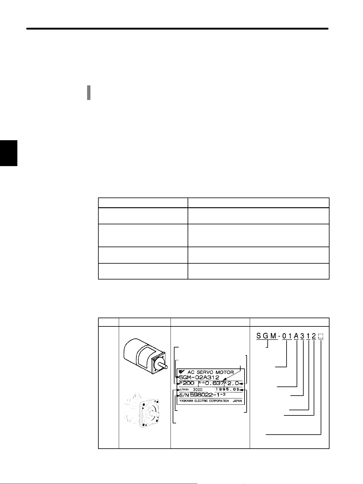
1) When Σ-Series products are delivered, check the following items:
Check Items
Check if the delivered products are
the ones you ordered.
Check if the motor shaft rotates
smoothly.
Check the types marked on the nameplates of
Servomotor and Servopack (see the table below).
If the motor shaft is smoothly turned by hand, it is
normal. However, if the motor has brakes, it cannot be
Remarks
turned manually.
Check for damage. Check the overall appearance, and check for damage
or scratches resulting from transportation.
Check screws for looseness. Check for looseness by using a screwdriver as
necessary.
If any of the above items are faulty or incorrect, contact the dealer from which you purchased the products or your nearest local sales representative.
Appearance Nameplate Type
Σ-Series
SGM: SGM
Servomotor
SGMP: SGM
Servomotor
Rated Output
A3:0.04HP A5:0.07HP
01:0.13HP 02:0.27HP
03:0.40HP 04:0.53HP
08:1.01HP
Power supply
A:200V B:100V
Encoder specifications
3: 2048P/R incremental encoder
W: 12-bit absolute encoder
Design revision order
Shaft specifications
2: Straight without key
4: Straight with key
6: Straight with key,
shaft end screw hole provided
Option
B: With brake S: With oil seal
D: With brake and oil seal
P: Drip-proof provision
Servo
motor
Σ-Series
SGM Servomotor
Σ-Series
SGMP Servomotor
Rated output
Servomotor
type
Serial number
Rated rotation
speed
Rated current
Rated torque
Manufacturing
date
18
Page 31

Appearance Nameplate Type
Servopack
Σ-Series SGDA
Servopack
2.2.2 Installing the Servomotor
Servomotor SGM and SGMP types can be installed either horizontally or vertically. However,
if the Servomotor is installed incorrectly or in an inappropriate location, the service life will be
shortened or unexpected problems will occur. To prevent this, always observe the installation
instructions described below.
Servopack type
Serial number
Output power voltage
Applicable power supply
Σ-Series
SGDA Servopack
Rated Ouoput
A3:0.04HP A5:0.07HP
01:0.13HP 02:0.27HP
03:0.40HP 04:0.53HP
08:1.01HP
Power Supply
Type
S: For speed/torque control
P: For position control
Applicable motor
Blank: SGM Servomotor
P: SGMP Servomotor
2.2 Installation
2
Before installation
:
Anticorrosive paint is coated on the edge of the motor shaft. Clean off the anticorrosive
paint thoroughly using a cloth moistened with thinner.
Anticorrosive paint is
coated here
NOTE Avoid getting thinner on other parts of the Servomotor when cleaning the shaft.
Storage:
When the Servomotor is to be stored with the power cable disconnected, store it in the
following temperature range:
Between −20°C and 60°C
Installation sites:
The Servomotor SGM and SGMP types are designed for indoor use.
Install Servomotor in an environment which meets the following conditions:
Free from corrosive and explosive gases
S
19
Page 32

BASIC USES OF Σ-SERIES PRODUCTS
2.2.2 Installing the Servomotorcont.
Well-ventilated and free from dust and moisture
S
Ambient temperature of 0 to 40°C
S
Relative humidity of 20% to 80% (non-condensing)
S
Inspection and cleaning can be performed easily
S
If the Servomotor is used in a location subject to water or oil mist, install a shield cover
over the Servomotor.
2
Alignment:
Align the shaft of the Servomotor with that of the equipment to be controlled, then connect
the shafts with couplings. Install the Servomotor so that alignment accuracy falls within
the range shown below.
Measure this distance at four different positions in the circumference. The
difference between the maximum and minimum measurements must be
0.03 mm or less. (Turn together with couplings)
Measure this distance at four different positions in the
circumference. The difference between the maximum and minimum
measurements must be 0.03 mm or less. (Turn together with
couplings)
NOTE If the shafts are not aligned properly, vibration will occur, resulting in damage to the bear-
ings.
2
Mechanical shock to the shaft end must be less than 98m/s
(10G) and must be
applied no more than twice.
Design the mechanical system so that thrust load and radial load applied to the servomotor shaft end during operation falls within the range shown in the following table.
20
TERMS
Thrust load and radial load
1. Thrust load: Shaft-end load applied parallel to the centerline of a shaft
2. Radial load: Shaft-end load applied perpendicular to
the centerline of a shaft
Motor
2.
1.
Shaft end
Page 33

• Servomotor with incremental encoder
2.2 Installation
Allowable
Motor Type
SGM-A3 68 (15) 54 (12) 20 (0.82)
SGM-A5 68 (15) 54 (12) 20 (0.82)
SGM-01 78 (17) 54 (12) 20 (0.82)
SGM-02 245 (55) 74 (16) 25 (1.02)
SGM-03 245 (55) 74 (16) 25 (1.02)
SGM-04 245 (55) 74 (16) 25 (1.02)
SGM-08 392 (88) 147 (33) 35 (1.43)
SGMP-01 78 (17) 49 (11) 20 (0.82)
SGMP-02 245 (55) 68 (15) 25 (1.02)
SGMP-03 245 (55) 68 (15) 25 (1.02)
SGMP-04 245 (55) 69 (15) 25 (1.02)
SGMP-08 392 (88) 147 (33) 35 (1.43)
Radial Load
Fr [N(lb)]
Allowable
Thrust Load
Fs [N(lb)]
LR
mm
(in.)
• Servomotor with absolute encoder
Allowable
Motor Type
SGM-A3 49 (11) 19 (4) 20 (0.82)
SGM-A5 68 (15) 19 (4) 20 (0.82)
SGM-01 68 (15) 19 (4) 20 (0.82)
SGM-02 196 (44) 49 (11) 25 (1.02)
SGM-03 196 (44) 49 (11) 25 (1.02)
SGM-04 196 (44) 68 (15) 25 (1.02)
SGM-08 343 (77) 98 (22) 35 (1.43)
SGMP-01 78 (17) 49 (11) 20 (0.82)
SGMP-02 245 (55) 68 (15) 25 (1.02)
SGMP-03 245 (55) 68 (15) 25 (1.02)
SGMP-04 245 (55) 69 (15) 25 (1.02)
SGMP-08 392 (88) 147 (33) 35 (1.43)
Radial Load
Fr [N(lb)]
Allowable
Thrust Load
Fs [N(lb)]
LR
mm
(in.)
Reference Drawing
LR
2
Reference Drawing
LR
Note The radial load and thrust load values shown above are the maximum allowed
values for the sum of the load generated by motor torque and the load externally
applied to the shaft.
21
Page 34

BASIC USES OF Σ-SERIES PRODUCTS
2.2.3 Installing the Servopack
2.2.3 Installing the Servopack
Σ-Series SGDA Servopack is a book-shaped compact
servo controller.
Incorrect installation will cause problems. Always observe the installation instructions described in the next
page.
Storage:
2
When the Servopack is to be stored with the power cable disconnected, store it in the following
temperature range:
Between −20°C and 85°C
Installation sites:
Situation Notes on Installation
Design the control panel size, unit layout, and cooling
When installed in a control panel
When installed near a heating
unit
When installed near a source of
vibration
When installed in a place
receiving corrosive gases
Others
method so that the temperature around the periphery of
the Servopack does not exceed 55°C.
Suppress radiation heat from the heating unit and a
temperature rise caused by convection so that the
temperature around the periphery of the Servopack does
not exceed 55°C.
Install a vibration isolator underneath the Servopack to
prevent it from receiving vibration.
Corrosive gases do not immediately affect the Servopack
but will eventually cause contactor-related devices to
malfunction. Take appropriate action to prevent corrosive
gases.
Avoid installation in a hot and humid place or where
excessive dust or iron powder is present in the air.
SGDA Servopack
22
Orientation:
Install the Servopack perpendicular to the wall as
shown in the figure.
The Servopack must be orientated as shown in
the figure because it is designed to be cooled by
natural convection.
Ventilation
• Firmly secure the Servopack through three or
four mounting holes.
Page 35

2.2 Installation
Installation method:
When installing multiple Servopacks side by side in a control panel, observe the following
installation method:
Fan
Fin
30 mm or more 10 mm or more
Fan
50 mm or more
50 mm or more
a) Install Servopack perpendicular to the wall so that the front panel (containing connec-
tors) faces outward.
b) Provide sufficient space around each Servopack to allow cooling by natural convec-
tion.
2
23
Page 36

BASIC USES OF Σ-SERIES PRODUCTS
2.2.3 Installing the Servopackcont.
c) When installing Servopacks side by side, provide at least 10 mm space between them
and at least 50 mm space above and below them as shown in the figure above. Install
cooling fans above the Servopacks to prevent the temperature around each Servopack from increasing excessively and also to maintain the temperature inside the
control panel evenly.
d) Maintain the following conditions inside the control panel:
• Ambient temperature for Servopack: 0 to 55°C
• Humidity: 90%RH or less
2
• Vibration: 0.5G (4.9 m/s
• Condensation and freezing: None
• Ambient temperature to ensure long-term reliability: 45°C or less
2
)
24
Page 37

2.3 Connection and Wiring
This section describes how to connect Σ-Series products to peripheral devices and
explains a typical example of wiring the main circuit. It also describes an example of
connecting to main host controllers.
2.3.1 Connecting to Peripheral Devices 25..................................
2.3.2 Main Circuit Wiring and Power ON Sequence 28.......................
2.3.3 Examples of Connecting I/O Signal Terminals 30.......................
2.3.1 Connecting to Peripheral Devices
This section shows a standard example of connecting Σ-Series products to peripheral devices and briefly explains how to connect to each peripheral device.
2.3 Connection and Wiring
2
25
Page 38

BASIC USES OF Σ-SERIES PRODUCTS
Standard connection method for Σ-Series AC Servo Drives:
Molded-case circuit breaker (MCCB)
Used to protect power
supply line. Shuts the
circuit off when
overcurrent is detected.
Noise filter
Used to eliminate
external noise from
power supply line.
Types: LF-205A (for SGDA-A3A, A5B, 01A, 02A,
A3B, A5B, and 01B)
LF-210 (for SGDA-04A and 02B)
LF-220 (for SGDA-03B and 08A)
Magnetic contactor
Turns the servo ON or OFF.
Use a surge suppressor for
the magnetic contactor.
Type: HI-15E5 (30 A)
Allows the user to set user constants or
Digital
operation references and display operation
status or alarm status. The following two
types are available in addition to personal
computers:
Power supply:
Single-phase
200 or 100 V
Mount type (JUSP-OP03A)
This type can be mounted directly on
the Servopack.
Σ-Series Servopack
Brake
control
relay
Brake power supply
Used for Servomotor with brake.
Regenerative unit
Type: JUSP-RG08
Exterior type regenerative
resistor
Type: JUSP-RG08C
26
Types:
LPSE-2H01 (for 200 V input)
LPDE-1H01 (for 100 V input)
This wiring is required
only for a Servomotor
with brake
Connector kits for pulse generator (PG) and for
motor are not required if the following parts are
ordered:
S Cable with terminal connectors
S Cable with connector and amplifier terminal
R
T
P
N
U
V
W
Connector for PG
(on Servopack side)
Page 39

2.3 Connection and Wiring
Operator
Hand-held type
(JUSP-OP02A-1)
1-meter(3.3ft.) cable included
1CN connector kit
(Type: DP9420007)
1-meter cable with 1CN connector and
one end without connector
(Type: DE9404859)
Personal computer
Exclusive-use cable between personal computer and
Servopack (for NEC PC) is available.
Type: DE9405258 (2m, 6.6ft.)
Consult factory about cable for IBM PC (IBM compatible
PC).
Connector terminal block conversion unit
(Type: JUSP-TA36P)
The terminal block
allows connection to a
host controller.
0.5-meter(1.6ft)
cable with two
1CN connectors
Host controller
Servopack is compatible with most P.L.C.
motion controllers and indexers.
References are input as analog
signals or pulse trains.
PROGIC-8
Cable for PG
This cable is used to connect a Servomotor
encoder to a Servopack.
The following two types of cable are available
according to the encoder type:
• Cable for incremental encoder (with connector
on both ends)
9.8ft: DP9320089-1 16.4ft: DP9320089-2
32.8ft: DP9320089-3 49.2ft: DP9320089-4
65.6ft: DP9320089-5
• Cable for absolute encoder (with connectors on
both ends)
9.8ft: DP9320088-1 16.4ft: DP9320088-2
32.8ft: DP9320088-3 49.2ft: DP9320088-4
65.6ft: DP9320088-5
A cable with a single connector (without connector
on Servopack side) and a cable without connectors
are also available.
Connector for
PG (on motor
side)
Connector
for motor
Σ-Series Servomotor
Connector kit for PG
On Servomotor
side
This connector kit is required for cables without connectors. For moving parts, a cable for robot must be
ordered separately.
Cable for motor
This is a power cable for connecting a Servomotor to a
Servopack.
For a Servomotor with brake, this cable is also used to wire the
brake.
• Without brake (connector and amplifier terminal included)
9.8ft: DP9320081-1 16.4ft: DP9320081-2
32.8ft: DP9320081-3 49.2ft: DP9320081-4
65.6ft: DP9320081-5
• With brake (connector and amplifier terminal included)
9.8ft: DP9320083-1 16.4ft: DP9320083-2
32.8ft: DP9320083-3 49.2ft: DP9320083-4
65.6ft: DP9320083-5
A cable without connector and amplifier terminal is also available.
Connector kit for motor
Connector for motor (on motor side)
This connector kit is required for cables without connector and
amplifier terminal.
On Servopack side
2CN
27
Page 40

BASIC USES OF Σ-SERIES PRODUCTS
2.3.2 Main Circuit Wiring and Power ON Sequence
2.3.2 Main Circuit Wiring and Power ON Sequence
1) The following diagram shows a typical example of wiring the main circuit for Σ-Series
products:
2
Single-phase 200 to 230 VAC 50/60 Hz
+ 10
% ,
–15
1MCCB: Circuit breaker
1FIL: Noise filter
1MC: Contactor
1Ry: Relay
1PL: Patrol light
1SUP: Surge suppressor
1D: Flywheel diode
For 100 V Type
Single-phase 100 to 115 VAC 50/60 Hz
+ 10
–15
% ,
28
2) The following table shows the name and description of each main circuit terminal:
Terminal
Symbol
RT
UV W
PN
* For 100 V power supply: Single-phase 100 to 115 VAC
Name Description
Main circuit AC
input terminal
Motor connection
terminal
Ground terminal
Single-phase 200 to 230 VAC , 50/60Hz
Connect U to the red motor terminal , V to the white motor
terminal, and W to the blue motor terminal
Connect to the motor ground terminal (green) for grounding
purposes.
Regenerative unit
connection
Connect to a regenerative unit when applicable.
terminal
+ 10
–15
+ 10
–15
%
%
, 50/60Hz
*
Page 41

2.3 Connection and Wiring
Servopack
ype
3) Form a power ON sequence as follows:
a) Form a power ON sequence so that the power is turned OFF when a servo alarm sig-
nal is output. (See the circuit diagram shown on the previous page.)
b) Hold down the power ON push-button for at least two seconds. The Servopack out-
puts a servo alarm signal for approximately two seconds or less when the power is
turned ON. This operation is required to initialize the Servopack.
Power supply
Servo alarm (ALM) output signal
NOTE After turning the power OFF,do not touch the power terminals for 5 minutes. High voltage
may remain in the Servopack.
2
• Avoidfrequently turning the power ON and OFF. Since the Servopack has a capacitor in
the power supply, a high charging current flows (for 0.2 second) when the power is
turned ON. Therefore, frequently turning the power ON and OFF causes the main power devices (such as capacitors and fuses) to deteriorate, resulting in unexpected problems.
• If the Servopack is turned ON immediately after being turned OFF, a power loss alarm
may arise. To prevent this, always wait for the time shown in the following table before
turning the power ON again:
Type
SGDA-
Single-phase 200
VAC
A3Aj, A5Aj A3Bj
01Aj, 02Aj, 04Aj A5Bj, 01Bj, 02Bj
08Aj
Single-phase 100 VAC Power Holding Time
6 seconds
10 seconds
03B 15 seconds
29
Page 42

BASIC USES OF Σ-SERIES PRODUCTS
2.3.3 Examples of Connecting I/O Signal Terminals
2.3.3 Examples of Connecting I/O Signal Terminals
1) This sub-section provides typical examples of connecting to main host controllers. Connection to other host controllers is also possible. Connect to the host controller according
to the connection examples shown below by referring to technical documentation for the
host controller.
NOTE This sub-section describes signals related to the SGDA Servopack only. For other sig-
nals, refer to the relevant technical documentation.
2) Example of Connecting to PROGIC-8
2
SGDA-jjj S
Speed/Torque
Servopack for Speed/Torque Control
Servopack
Yaskawa
MC unit
Not used
(Reserved)
FG (connector frame)
30
*1 These pin numbers are also applicable to SV2 to SV4.
*2 Do not change the standard settings of user constants for the Servopack.
Page 43

3) Example of Connecting to GL-Series Positioning Module B2833
2.3 Connection and Wiring
SGDA-jjj S
Speed/Torque
Servopack for Speed/Torque Control
(MADE BY YASKAWA)
SERVO NORMAL
35
DECEL LS
D/A OUTPUT
ALARM
SERVOPACK
2
*1
* These signals are output for approximately
two seconds when the power is turned ON.
Take this into consideration when designing a
power ON sequence.
Relay 1Ry is used to stop main circuit power
supply to the Servopack.
31
Page 44

BASIC USES OF Σ-SERIES PRODUCTS
2.3.3 Examples of Connecting I/O Signal Terminalscont.
4) Example of Connecting to GL-Series Positioning Module B2813
2
SGDA-jjj P
Positions
Servopack for Position Control
(MADE BY YASKAWA)
SERVO
NORMAL
DECELERA-
35
TION LS
ALARM
Servopack
*1 These signals are output for approximately
two seconds when the power is turned ON.
Take this into consideration when designing a
power ON sequence. Relay 1Ry is used to
stop main circuit power supply to Servopack.
*2 Change the Cn-02 setting as follows:
Bit No. 3 = 1
Bit No. 4 = 0
Bit No. 5 = 0
*3 Pull up the CLR signal with 1 kΩ
resistance.
Change the Cn-02 setting as follows:
Bit No. A =1
*2
32
Page 45

2.3 Connection and Wiring
5) Example of Connecting to OMRON Position Control Unit C500-NC222
SGDA-jjj S
Speed/Torque
Servopack for Speed/Torque Control
I/O POWER
SUPPLY
C500-NC222
(MADE BY OMRON)
SERVOX
0
X-AXIS (Y-AXIS)
2 (3)
11
12
(ON when
positioning is
stopped)
(ON when
proximity is
detected)
*1
Servopack
SGDA-VVVS
2
*1 These signals are output for approximately two seconds when the power is turned
ON. Take this into consideration when designing a power ON sequence. Relay 1Ry is
used to stop main circuit power supply to Servopack.
Note The signals shown here are applicable only to OMRON Sequencer
C500-NC222 and Yaskawa Servopack SGDA-VVVS.
33
Page 46

BASIC USES OF Σ-SERIES PRODUCTS
2.3.3 Examples of Connecting I/O Signal Terminalscont.
6) Example of Connecting to OMRON Position Control Unit C500-NC112
2
SGDA-jjj P
Positions
Servopack for Position Control
I/O
POWER
SUPPLY
C500-NC112
(MADE BY OMRON)
CW LIMIT
CCW LIMIT
EMERGENCY STOP
EXTERNAL INTERRUPT
HOME POSITION
HOME POSITION
PROXIMITY
LOCAL
READY
PULSE OUTPUT
CW + CCW
DIRECTION
OUTPUT
CW
*1 These signals are output for approximately two seconds when the power is turned ON. Take this
into consideration when designing a power ON sequence. Relay 1Ry is used to stop main circuit
power supply to Servopack.
*2 Change the Cn-02 setting as follows:
Bit No. 3 = 1
Bit No. 4 = 0
Bit No. 5 = 0
Note The signals shown here are applicable only to OMRON Sequencer C500-NC112 and
Yaskawa Servopack SGDA-VVVP.
+24V
(ON when proximity is detected)
11A
11B
12A
12B
7A
7B
+24V
+5V
024V
SERVOPACK
EXTERNAL
POWER
SUPPLY
34
Page 47

7) Example of Connecting to MITSUBISHI Positioning Unit AD72
2.3 Connection and Wiring
SGDA-jjj S
Speed/Torque
Servopack for Speed/Torque Control
I/O POWER SUPPLY
AD72
(MADE BY MITSUBISHI)
SPEED
REFERENCE
(ON when positioning is stopped)
(ON when proximity
is detected)
SERVOPACK
2
*1 These signals are output for approximately two seconds when the power is turned ON. Take this into
consideration when designing a power ON sequence. Relay 1Ry is used to stop main circuit power
supply to Servopack.
*2 These pin numbers are the same for both X and Y axes.
Note The signals shown here are applicable only to MITSUBISHI Sequencer AD72 and Yas-
kawa Servopack SGDA-VVVS.
35
Page 48

BASIC USES OF Σ-SERIES PRODUCTS
2.3.3 Examples of Connecting I/O Signal Terminalscont.
8) Example of Connecting to MITSUBISHI Positioning Unit AD71 (B Type)
2
SGDA-jjj P
Positions
Servopack for Position Control
I/O POWER SUPPLY
AD71 (B TYPE)
(MADE BY MITSUBISHI)
X AXIS (Y AXIS)
(ON when proximity
is detected)
(ON when positioning
is stopped)
19
SERVOPACK
024V
EXTERNAL
POWER
SUPPLY
+24V
36
*1 These signals are output for approximately two seconds when the power is turned ON. Take this into
consideration when designing a power ON sequence. Relay 1Ry is used to stop main circuit power
supply to Servopack.
*2 Manufactured by Yaskawa Controls Co., Ltd.
Note The signals shown here are applicable only to MITSUBISHI Sequencer AD71 (B Type)
and Yaskawa Servopack SGDA-VVVP.
Page 49

2.4Conducting a Test Run
This section describes how to conduct a full test run. The test run is divided into two
steps. Complete a test run in step 1 first, then proceed to step 2.
2.4.1 Test Run in Two Steps 37...........................................
2.4.2 Step 1: Conducting a Test Run for Motor without Load 39................
2.4.3 Step 2: Conducting a Test Run with the Motor Connected to the Machine 44
2.4.4 Supplementary Information on Test Run 46............................
2.4.5 Minimum User Constants Required and Input Signals 48................
2.4.1 Test Run in Two Steps
Conduct the test run when wiring is complete.
2.4 Conducting a Test Run
2
Generally, conducting a test run for servo drives can be difficult. However, by following the two
steps described below, the test run can be performed safely and correctly.
NOTE To prevent accidents, initially conduct a test run only for a servomotor under no load (i.e., with
all couplings and belts disconnected). Do not run the servomotor while it is connected to a
machine.
The test run is divided here into steps 1 and 2.
Complete the test run in step 1 first, then proceed to step 2. The purposes of each step are
described on the next page.
37
Page 50

BASIC USES OF Σ-SERIES PRODUCTS
2.4.1 Test Run in Two Stepscont.
Step 1: Conducting a test run for the motor without load Check that the motor is wired correctly....
2
Operate the motor with a Digital
Operator.
Check wiring.
Do not connect to a machine.
Step 2: Conducting a test run with the motor and
machine connected Adjust Servopack according to machine.................................
Speed adjustment by
autotuning
Conduct a test run with the motor shaft disconnected
from the machine.
Purpose:
Outline:
Connect to the machine and conduct a test run.
Purpose:
• To check power supply circuit wiring
• To check motor wiring
• To check I/O signal (1CN) wiring
• Turn the power ON.
• Operate the motor with a digital op-
erator.
• Check I/O signals (1CN).
• Conduct a test run using I/O signals.
characteristics.
• To perform autotuning to adjust the motor according to machine characteristics
• To match the speed and direction of
rotation with the machine specifications
• To check the final control mode
Connect to the machine.
Outline:
End of test run
• Perform autotuning.
• Adjust user constant settings.
• Record user constant settings.
For customers who use a servomotor with a brake, refer to Section 2.4.4 Supplementary
Information on Test Run before starting a test run.
The following pages describe the test run procedure in detail.
38
Page 51

2.4 Conducting a Test Run
2.4.2 Step 1: Conducting a Test Run for Motor without Load
Check that the motor is wired correctly.
If the motor fails to rotate properly during a servo drive test run, the cause most frequently lies
in incorrect wiring.
Conduct a test run for the motor without load according to the procedure described below.
For customers who use a servomotor with brake, refer to Section 2.4.4 Supplemental In-
formation on Test Run before starting a test run.
Operate the motor with
a Digital Operator.
2
Check wiring.
Do not connect to the machine.
(1) Secure the servomotor.
Secure the servomotor to mounting holes to
prevent it from moving during operation. Alternatively, install the servomotor on the machine
and disconnect couplings and belts.
(2) Disconnect connector 1CN, then check the
motor wiring in the power supply circuit.
I/O signals (1CN) are not to be used so leave
connector 1CN disconnected.
Note: When absolute encoder is used, connect
the battery. Also, initialize the absolute
encoder.
See 3.8.5 Using an Absolute Encoder
for details.
Secure servomotor to mounting holes.
Do not connect
anything to the
motor shaft
(no-load
status).
Disconnect
connector
1CN
(3) Short the alarm signal circuit.
Because connector 1CN is disconnected, the
alarm signal prevents the power supply circuit
from being turned ON. Therefore, temporarily
short the alarm signal circuit.
Power supply
0V +24V
Short this
circuit.
Force this relay ON.
1CN disconnected
39
Page 52

BASIC USES OF Σ-SERIES PRODUCTS
2.4.2 Step 1: Conducting a Test Run for Motor without Loadcont.
2
(4) Turn the power ON.
Turn the Servopack power ON. If the Servopack is turned ON normally, the LED on the
Digital Operator lights up as shown in the figure.
Power is not supplied to the servomotor because the servo is OFF.
If an alarm display appears on the LED as
shown in the figure above, the power supply
circuit, motor wiring or encoder wiring is incorrect. In this case, turn the power OFF,then correct the problem.
Note: When absolute encoder is used, perform
the following procedures after turning ON
the power.
Set the bit E of Cn−01 to 1.
1
2
Set the number of encoder pulses (Cn−11)
to 1024.
Normal display
Alternately displayed
Example of alarm display
Refer to Appen-
dix E List of
Alarm Displays.
3
Set the dividing ratio of encoder pulses
(Cn−0A) to 1024 or below.
4
Turn OFF the power once. Then turn ON
the power again after checking if the displays
of digital operator extinguish.
(5) Operate using the Digital Operator
Operate the motor with the Digital Operator.
Check that the motor runs normally.
Refer to 4.2.2 Operating Using the Digital Op-
erator.
Operation by Digital Operator
If an alarm occurs, the power supply
circuit, motor wiring, or encoder
wiring is incorrect.
40
Page 53

2.4 Conducting a Test Run
(6) Connect signal lines.
Connect connector 1CN as follows:
(1) Turn the power OFF.
(2) Retrun the alarm signal circuit shorted in
the above step (3) to its original state.
(3) Connect connector 1CN.
(4) Turn the power ON again.
(7) Check input signals.
Check the input signal wiring in monitor mode.
For the checking method, refer to 4.1.6 Opera-
tion in Monitor Mode.
• Checking method
Turn each connected signal line ON and
OFF to check that the monitor bit display
changes accordingly.
After turning the power OFF, remove the short circuit.
Example of
Un-05
S-ON
(1CN-14)
Internal status bit display
(Un-05, Un-06)
N-CL
(1CN-12)
P-CON
(1CN-17)
The memory switch can be
used to
eliminate the need
for external short-circuits in
wiring (see pages 55 and
128).
Connect
connector
1CN.
P-CL
(1CN-11)
P-OT
(1CN-16)
2
N-OT
(1CN-17)
Input Signal ON/OFF Monitor Bit Display
High level or open OFF Extinguished
0 V level ON Lit
If the signal lines below are not wired correctly, the motor fails to rotate. Always wire
them correctly. (If signal lines are not to be used, short them as necessary.)
P-OT 1CN-16 Motor can rotate in forward direction when this input signal is at 0 V.
N-OT 1CN-17 Motor can reverse when this input signal is at 0 V.
S-ON 1CN-14 Servo is turned ON when this input signal is at 0 V. However, leave
the servo in OFF status.
(8) Turn servo (motor) ON.
Servopack
Servomotor
Turn the servo ON as follows:
(1) Check that no reference has been input.
Turn the servo ON
For speed/torque control (SGDA-
jjj
S):
V-REF (1CN-3) and T-REF (1CN-1) are at 0 V.
For position control (SGDA-
jjj
P):
PULS (1CN-1) and SIGN (1CN-3) are fixed.
41
Page 54

BASIC USES OF Σ-SERIES PRODUCTS
2.4.2 Step 1: Conducting a Test Run for Motor without Loadcont.
2
SGDA- S
Speed/Torque
(2) Turn the servo ON signal ON.
Display when servo is turned ON
Set S-ON (1CN-14) to 0 V. If normal, the motor
is turned ON and the Digital Operator displays
the data as shown in the figure. If an alarm display appears, take appropriate action as described in Appendix E List of Alarm Displays.
(9) Operate by reference input.
The operating procedure differs according to the Servopack control mode used.
Servopack for Speed/Torque
(This section describes the standard speed con-
Servopack
trol setting.)
(1) Gradually increase the speed reference input
(V-REF, 1CN-3) voltage. The motor will rotate.
Servomotor rotates at a speed
proportional to the reference voltage.
Servomotor
When a host controller such as a programmable controller performs position
control, it may be difficult to directly input the speed reference voltage. In this
case, constant voltage reference should be input once to ensure correct operation.
(2) Check the following items in monitor mode (see page 179):
(1) Has a reference speed been input?
(2) Is the motor speed as set?
(3) Does the reference speed match the actual motor speed?
(4) Does the motor stop when no reference is input?
Un-00
Actual motor speed
Un-01 Reference speed
(3) If the motor rotates at an extremely slow speed when 0 V is specified as the reference
voltage, correct the reference offset value as described in Section 4.2.4 Reference
Offset Automatic Adjustment
42
Page 55

2.4 Conducting a Test Run
Cn-02
(4) To change motor speed or the direction of rotation, reset the user constants shown
below.
SGDA-jjjP
Positions
Cn-03
Speed reference gain (see page 68)
Cn-02 bit 0 Reverse rotation mode (see page 54)
Servopack for Position Control
(1) Set user constant Cn-02 so that the reference pulse form matches the host controller
output form. (See page 174 for details on how to set user constants.)
Selecting reference pulse form (See page 70)
Bit 3
Bit 4
Bit 5
Bit D
(2) Input a slow speed pulses from the host con-
troller and execute low-speed operation.
Host
controller
Reference
pulse
Servopack
(3) Check the following items in monitor mode
(see page 179):
2
Servomotor
(1) Has a reference pulse been input?
(2) Is the motor speed as set?
(3) Does the reference speed match the actual motor speed?
(4) Does the motor stop when no reference is input?
Un-00
Actual motor speed
Un-07 Reference pulse speed display
Un-08 Position error
43
Page 56

BASIC USES OF Σ-SERIES PRODUCTS
2.4.3 Step 2: Conducting a Test Run with the Motor Connected to the Machine
(4) To change motor speed or the direction of rotation, reset the user constants shown
below.
2
Cn-24,Cn-25
Cn-02 bit 0 Reverse rotation mode (see page 54)
If an alarm occurs or the motor fails to rotate during the above operation, connector 1CN wiring is incorrect or the user constant settings do not match the host controller specifications.
In this case, check the wiring and review the user constant settings, then repeat
step 1.
Refer to Appendix E List of Alarm Displays and Appendix D List of User Constants.
This is all that is required to complete step 1 (conducting a test run for motor without load).
Whenever possible, perform tuning associated with the host controller and other necessary adjustments in step 1 (before installing the motor on the machine).
Electronic gear ratio (see page 81)
2.4.3 Step 2: Conducting a Test Run with the Motor Connected to
the Machine
After step 1 is complete, proceed to step 2 in which a test run is conducted with the motor
connected to the machine. The purpose of step 2 is to adjust the Servopack according to the
machine characteristics.
Conduct a test run according to the procedure described below.
Purposes: 1) Autotuning
SGDA
Servopack
NOTE Before proceeding to step 2, repeat step 1 (conducting a test run for the motor without load)
until you are fully satisfied that the test has been completed successfully. Operation faults that
arise after the motor is connected to the machine not only damage the machine but may also
cause an accident resulting in injury or death. Therefore, all items including user constants
setting and wiring should be tested as conclusively as possible before step 1 is complete.
Servomotor
Connect to the machine.
2) Speed adjustment
44
Page 57

2.4 Conducting a Test Run
(1) Check that power is OFF.
Turn the Servopack power OFF.
(2) Connect the servomotor to the machine.
Refer to 2.2.2 Installing the Servomotor.
(3) Perform autotuning.
Tune the Servopack according to the machine
characteristics. Refer to 4.2.3 Autotuning.
Power
supply
Power OFF
Install servomotor on machine.
Servomotor
Autotuning:
Automatically measures
machine characteristics and
performs optimum tuning
Servopack Servomotor
Servopack
2
(4) Operate by reference input.
As in step 1 (conducting a test run for motor
without load), perform (9) Operate by refer-
ence input on page 42. Perform tuning
Host
controller
Reference
Servopack
Servomotor
associated with the host controller.
(5) Set user constants and record the settings.
Set user constants as necessary. Record all
the user constant settings for maintenance
purposes.
Servopack
User constants
Record the settings
This is all that is required to conduct the test run.
Normally, the machine may cause much friction because of an insufficient running-in period. After a test run is complete, perform adequate running-in.
45
Page 58

2
BASIC USES OF Σ-SERIES PRODUCTS
2.4.4 Supplementary Information on Test Run
2.4.4 Supplementary Information on Test Run
In the following cases, always refer to the information described below before starting a test
run:
• When using a servomotor with a brake
• When performing position control from the host controller
1) When using a servomotor with brake
The brake prevents the motor shaft from rotating due to a backdriving torque. Such a
torque may be created by an external force or the force of gravity acting on the load and
may result in undesired motion or the load, should motor power be lost.
Servopack uses the brake interlock output (BK) signal to control holding brake operation
for a servomotor with brake.
• Vertical axis
Servomotor
Holding brake
Prevents the
motor from
rotating due to
gravity
• Axis to which external force is applied
External force
Servomotor
NOTE Toprevent faulty operation caused by gravity (or external force), first check that the motor
and holding brake operate normally with the motor disconnected from the machine.
Then, connect the motor to the machine and conduct a test run.
For wiring of a servomotor with a brake, refer to 3.4.4 Using Holding Brake.
Power supply:
single-phase
Brake control relay
Brake power supply
LPSE-2H01 (200 V input)
LPDE-1H01 (100 V input)
200 V or 100 V
Servopack
Cable for motor with
brake
9.8ft DP9320083-1
16.4ft DP9320083-2
32.8ft DP9320083-3
49.2ft DP9320083-4
65.6ft DP9320083-5
46
Servomotor with brake
Page 59

2.4 Conducting a Test Run
2) When performing position control from the host controller
Check motor operation first and then conduct a test run as described in the table below.
For speed control
Type:
Speed
Host
controller
Position
control
reference
Speed
control
Test run
for motor
without
load
2
NOTE Check the motor operation with the motor disconnected from the machine. If the host con-
troller does not perform position control correctly, the motor may run out of control.
Reference from
Host Controller
Jogging
(constant-speed
reference input from
host controller)
Simple positioning
Overtravel (when
P-OT and N-OT
signals are used)
Check Items Check Method Review Items
Check the motor
speed as follows:
D Use the speed
monitor (Un-00) of
the digital operator.
Check whether the
speed reference gain
value (user constant
Cn-03) is correct.
Check whether the
dividing ratio count
(user constant
Cn-0A) is correct.
If the motor does not
stop, review the
P-OT and N-OT
wiring.
Motor speed
Number of motor
revolutions
Whether the motor
stops rotating when
P-OT and N-OT
signals are input
D Run the motor at
low speed. For
example, input a
speed reference of
60 r/min and check
that the motor
makes one
revolution per one
second.
D Input a reference
equivalent to one
motor revolution
and visually check
that the motor shaft
makes one
revolution.
D Check that the
motor stops when
P-OT and N-OT
signals are input
during continuous
motor operation.
47
Page 60

BASIC USES OF Σ-SERIES PRODUCTS
2.4.5 Minimum User Constants Required and Input Signals
2.4.5 Minimum User Constants Required and Input Signals
1) This section describes the minimum user constants that must be set to conduct a test run.
For details on how to set each user constant, refer to 4.1.5 Operation in User Constant
Setting Mode.
a) Servopack for speed/torque control
2
Cn-01 bit E
Cn-02 bit 8 Motor selection
Cn-03 Speed reference adjustment gain
Cn-0A Encoder pulse dividing ratio
Cn-11 Number of encoder pulse
b) Servopack for position control
Cn-01 bit E
Cn-02 bit 8 Motor selection
Cn-02 bits 3,4,5 Reference pulse form selection
Cn-02 bit D Logic of reference pulse
Cn-02 bit F Reference pulse output form
Cn-0A Encoder pulse dividing ratio
Cn-11 Number of encoder pulses
Cn-24 Electronic gear ratio (numerator)
Cn-25 Electronic gear ratio (denominator)
After changing the Cn-02 setting, always turn the power OFF, then ON. This makes
the new setting valid.
Encoder selection
Encoder selection
alone
48
2) If the specified direction of rotation differs from the actual direction of rotation, the wiring
may be incorrect. In this case, recheck the wiring and correct it accordingly. Then, if the
direction of rotation is to be reversed, set the following user constant:
Cn-02 (bit 0)
After changing the Cn-02 setting, always turn the power OFF, then ON. This makes the
new setting valid.
3) The following table lists the minimum input signals required to conduct a test run. For details of each input signal, refer to the relevant page.
Reverse rotation mode (see page 54)
Page 61

2.4 Conducting a Test Run
Signal Name
S-ON (servo ON) 1CN-14
(forward
P-OT
N-OT
rotation
prohibited)
(revere
rotation
prohibited)
Pin
Number
1CN-16
1CN-17
Function
Switching between motor ON and OFF status.The
memory switch can be used to eliminate the need for
external short-circuit wiring (see page 129).
Overtravel limit switch
The memory switch can be used to eliminate the
need for external short-circuit wiring (see page 57).
2
49
Page 62

APPLICATIONS OF Σ-SERIES
PRODUCTS
This chapter is prepared for readers who wish to learn more about the applications of Σ-series products after fully understanding Chapter 2 Basic Uses of
Σ-series Products. It explains how to set user constants for each purpose and
how to use each function. Read the applicable sections according to your requirements.
3.1 Setting User Constants
3.2 Setting User Constants
3
3
According to Machine Characteristics 54.......
3.1.1 Changing the Direction of Motor Rotation 54................
3.1.2 Setting the Overtravel Limit Function 56...................
3.1.3 Restricting Torque 59...................................
According to Host Controller 65...............
3.2.1 Inputting Speed Reference 65............................
3.2.2 Inputting Position Reference 69..........................
3.2.3 Using Encoder Output 73...............................
3.2.4 Using Contact I/O Signals 77............................
3.2.5 Using Electronic Gear 79................................
3.2.6 Using Contact Input Speed Control 83.....................
3.2.7 Using Torque Control 88................................
3.2.8 Using Torque Feed-forward Function 94....................
3.2.9 Using Torque Restriction by Analog Voltage Reference 95.....
3.2.10 Using the Reference Pulse Inhibit Function (INHIBIT) 97......
3.2.11 Using the Reference Pulse Input Filter Selection Function 99...
3.3 Setting Up theΣServopack 100................
3.3.1 Setting User Constants 100...............................
3.3.2 Setting the Jog Speed 101................................
3.3.3 Setting the Number of Encoder Pulses 102...................
3.3.4 Setting the Motor Type 103...............................
3.4 Setting Stop Mode 104........................
3.4.1 Adjusting Offset 104....................................
3.4.2 Using Dynamic Brake 105................................
3.4.3 Using Zero-Clamp 106..................................
3.4.4 Using Holding Brake 107................................
51
Page 63

3
Chapter Table of Contents, Continued
3.5 Running the Motor Smoothly 111...............
3.5.1 Using the Soft Start Function 111..........................
3.5.2 Using the Smoothing Function 112.........................
3.5.3 Adjusting Gain 112.....................................
3.5.4 Adjusting Offset 113....................................
3.5.5 Setting the Torque Reference Filter Time Constant 113.........
3.6 Minimizing Positioning Time 114...............
3.6.1 Using Autotuning Function 114...........................
3.6.2 Setting Servo Gain 114..................................
3.6.3 Using Feed-forward Control 116...........................
3.6.4 Using Proportional Control 116............................
3.6.5 Setting Speed Bias 117..................................
3.6.6 Using Mode Switch 118.................................
3.6.7 Using Speed Loop Compensation Function 124...............
3.7 Forming a Protective Sequence 125.............
3.7.1 Using Servo Alarm Output and Alarm Code Output 125........
3.7.2 Using Servo ON Input Signal 128..........................
3.7.3 Using Positioning Complete Signal 129.....................
3.7.4 Using Speed Coincidence Output Signal 131.................
3.7.5 Using Running Output Signal 132..........................
3.7.6 Handling of Power Loss 134..............................
3.8 Special Wiring 136...........................
3.8.1 Wiring Instructions 136..................................
3.8.2 Wiring for Noise Control 138.............................
3.8.3 Using More Than One Servo Drive 143.....................
3.8.4 Using Regenerative Units 144.............................
3.8.5 Using an Absolute Encoder 148...........................
3.8.6 Extending an Encoder Cable 157..........................
3.8.7 Using SGDA Servopack with High Voltage Line 159..........
3.8.8 Connector Terminal Layouts 161..........................
52
Page 64

Before Reading this Chapter
1) This chapter describes how to use each 1CN connector I/O signal for the SGDA Servopack and how to set the corresponding user constant.
2) For a list of I/O signals of 1CN connecor, refer to Appendix C List of I/O Signals.
For terminal arrangement for I/O signals of 1CN connecor, refer to 3.8.8 Connector Ter-
minal Layouts.
I/O signals
3) For a list of user constants, refer to Appendix D List of User Constants.
4) User constants are divided into the following two types.
1) Memory switch
Cn-01 and Cn-02
2) Constant setting
Cn-03 and later
Set each bit to ON or OFF to select a function.
Set a numerical value such as a torque limit
value or speed loop gain.
SGDA Servopack
User constants
Host controller,
external circuit
3
5) For details on how to set user constants, refer to 4.1.5 Operation in User Constant Setting
Mode.
53
Page 65

APPLICATIONS OF Σ-SERIES PRODUCTS
3.1.1 Changing the Direction of Motor Rotation
3.1 Setting User Constants According to Machine Characteristics
This section describes how to set user constants according to the dimensions and
performance of the machine to be used.
3.1.1 Changing the Direction of Motor Rotation 54...........................
3.1.2 Setting the Overtravel Limit Function 56...............................
3.1.3 Restricting Torque 59...............................................
3.1.1 Changing the Direction of Motor Rotation
3
1) This Servopack provides a reverse rotation mode in which the direction of rotation can be
reversed without altering the servomotor wiring. With the standard setting, forward
rotation is defined as counterclockwise (ccw) rotation viewed from the drive end.
2) If reverse rotation mode is used, the direction of motor rotation can be reversed without
other items being changed. The direction (+/−) of axial motion is reversed.
Standard Setting Reverse Rotation Mode
Forward Run Reference
Reverse Run Reference
Encoder output
from Servopack
(Phase A)
(Phase B)
Encoder output
from Servopack
(Phase A)
(Phase B)
Encoder output
from Servopack
(Phase A)
(Phase B)
Encoder output
from Servopack
(Phase A)
(Phase B)
54
Page 66

3.1Setting User Constants According to Machine Characteristics
3) Setting Reverse Rotation Mode:
Reverse rotation mode can be set in either of the following two ways. Normally, method 1
is easier to use.
a) Method 1: Setting Memory Switch
Set bit 0 of memory switch Cn-02 to select reverse rotation mode.
Cn-02 Bit 0
Rotation Direction
Selection
Factory
Setting: 0
Set the direction of rotation.
Setting Meaning
Forward rotation is
defined as
0
counterclockwise
rotation when viewed
from the drive end.
Forward rotation is
defined as clockwise
1
rotation when viewed
from the drive end.
Method 2: Shorting the Wiring in the 2CN Connector
b)
Reverse rotation mode can be set for the 2CN
connector for the encoder. This method is used
to standardize user constant settings without
using the memory switch.
In this case, reverse rotation mode is set
regardless of the memory switch setting.
(Standard
setting)
(Reverse
rotation
mode)
Servopack Servomotor
For Speed/Torque Control
and Position Control
3
Encoder
Servopack
Short 2CN-1 and 2CN-7 in
the 2CN connector.
55
Page 67

APPLICATIONS OF Σ-SERIES PRODUCTS
3.1.2 Setting the Overtravel Limit Function
3.1.2 Setting the Overtravel Limit Function
1) The overtravel limit function forces the moving part of the machine to stop when it exceeds the movable range.
2) To use the overtravel limit function, connect the following input signal terminals correctly.
3
Forward Rotation Prohibited
→ Input P-OT 1CN-16
→ Input N-OT 1CN-17
(Forward Overtravel)
Reverse Rotation Prohibited
(Reverse Overtravel)
Inputs terminals for overtravel limit switch.
For linear motion, connect a limit switch to prevent
damage to the machine.
P-OT
N-OT
ON: 1CN-16 is
at low level.
OFF: 1CN-16
is at high level.
ON: 1CN-17 is
at low level.
OFF: 1CN-17
is at high level.
Forward rotation allowed. Normal operation status.
Forward rotation prohibited (reverse rotation allowed).
Reverse rotation allowed. Normal operation status.
Reverse rotation prohibited (forward rotation allowed).
Reverse
rotation side
Servomotor
For Speed/Torque
Control and
Position Control
For Speed/Torque
Control and
Position Control
Forward
rotation side
Limit switch
Servopack
56
Page 68

3.1Setting User Constants According to Machine Characteristics
3) Use the following user constants (memory switch) to specify whether input signals for
overtravel are to be used.
Cn-01 Bit 2
Cn-01 Bit 3
Use of P-OT Input Signal Factory
Setting: 0
Use of N-OT Input Signal Factory
Setting: 0
Specifies whether the P-OT input signal for prohibiting forward rotation at overtravel (1CN-16) is
to be used and whether the N-OT input signal for
prohibiting reverse rotation at overtravel
(1CN-17) is to be used.
Specifies “1” when external short-circuit wiring is
to be omitted.
Bit Setting Meaning
Uses the P-OT input signal for prohibiting forward rotation. (Forward
0
rotation is prohibited when 1CN-16 is open. Forward rotation is allowed
Bit 2
Bit 3
when 1CN-16 is at 0 V.)
Does not use the P-OT input signal for prohibiting forward rotation.
1
(Forward rotation is always allowed. This has the same effect as shorting
1CN-16 to 0 V.)
Uses the N-OT input signal for prohibiting reverse rotation. (Reverse
0
rotation is prohibited when 1CN-17 is open. Reverse rotation is allowed
when 1CN-17 is at 0 V.)
Does not use the N-OT input signal for prohibiting reverse rotation.
(Reverse rotation is always allowed. This has the same effect as shorting
1
1CN-17 to 0 V.)
For Speed/Torque Control
and Position Control
For Speed/Torque Control
and Position Control
Servopack
The short-circuit wiring shown in the
figure can be omitted when P-OT and
N-OT are not used.
3
4) If the P-OT and N-OT input signals are used, set the following user constants to specify
how to stop the motor.
Cn-01 Bit 8
How to Stop Motor at
Overtravel
Operation to be Performed
Cn-01 Bit 9
when Motor Stops after
Overtravel
• Inputs signal for prohibiting forward rotation
(P-OT, 1CN-16)
• Inputs signal for prohibiting reverse rotation
(N-OT, 1CN-17)
Specify how to stop the motor when either of the
above signals is input.
Factory
Setting: 0
Factory
Setting: 0
Overtravel
0
Bit 8
1
For Speed/Torque Control
and Position Control
For Speed/Torque Control
and Position Control
Stop mode After stop
Stop by
0
Bit 6
1
dynamic brake
Coasting to a
stop
Deceleration
stop
Releasing
dynamic brake
Servo OFF
0
Bit 9
Zero-clamp
1
57
Page 69

APPLICATIONS OF Σ-SERIES PRODUCTS
3.1.2 Setting the Overtravel Limit Functioncont.
Setting Meaning
0
Cn-01
bit 8
1
If deceleration stop mode is selected, specify the operation to be done after the motor
stops.
Setting Meaning
Cn-01
bit 9
0
1
Stops the motor in the same way as when the servo is turned OFF.
The motor is stopped by dynamic brake or coasts to a stop. Either of
these stop modes can be selected by setting bit 6 of Cn-01.
Stops the motor by decelerating it with the preset torque.
Preset value: Cn-06 (EMGTRQ) emergency stop torque
Turns the servo OFF when the motor stops in deceleration stop mode.
Causes the motor to enter zero-clamp status after it stops in deceleration
stop mode.
3
If torque control mode is selected for the Servopack for speed/torque control
(SGDA-jjjS), the motor stops in the same way as when the servo is turned OFF,
regardless of the setting of Cn-01 bit 8.
EMGTRQ
Cn-06
Emergency Stop
Torque
Specifies the stop torque to be applied at overtravel when the input signal for prohibiting forward or
reverse rotation is to be used.
Specifies a torque value in terms of a percentage
of the rated torque.
Cn-01 Bit 6
Cn-01 Bit 7
How to Stop Motor at Servo
OFF
Operation to Be Performed
when Motor Stops after Servo
OFF
Unit:%Setting
Range: 0 to
Maximum
Torque
Input signal for
prohibiting
forward rotation
P-OT (1CN-16)
Input signal for
prohibiting reverse
rotation
N-OT (1CN-17)
Factory
Setting: 0
Factory
Setting: 1
Factory
Setting:
Maximum
For Speed/Torque
Control and Position
Control
Torque
Memory
switch
For Speed/Torque Control
and Position Control
For Speed/Torque Control
and Position Control
Emergency
stop torque
Stop by
dynamic brake
Coasting to a
stop
58
The Servopack enters servo OFF status when:
• Servo ON input signal (S-ON, 1CN-14) is turned
OFF.
• Servo alarm arises.
• Power is turned OFF.
Specify how to stop the motor when one of the
above events occurs during operation.
Servo OFF
Stop mode
Stop by
dynamic brake
0
Bit 6
1
Coasting to a
stop
Dynamic brake is a function that
electrically applies brakes by using a
resistor to consume motor rotation
energy.
After stop
Releasing
dynamic brake
0
Bit 7
Holding
1
dynamic brake
Page 70

Setting Meaning
Cn-01
0
Cn-01
bit 6
Stops the motor by dynamic brake.
Causes the motor to coast to a stop.
1
The motor power is OFF and stops due to machine friction.
If dynamic brake stop mode is selected, specify the operation to be performed when the
motor stops.
Setting Meaning
0
Cn-01
bit 7
Releases dynamic brake after the motor stops.
Does not release dynamic brake even after the motor stops.
1
3.1.3 Restricting Torque
3.1Setting User Constants According to Machine Characteristics
1) The Servopack can provide the following torque control:
D Torque restriction Level 1: To restrict the maximum output torque to
protect the machine or workpiece
Level 2: To restrict torque after the motor moves the
machine to a specified position
D Torque control Level 3: To always control output torque, not speed
Level 4: To alternately use speed control and torque
control
This section describes how to use levels 1 and 2 of the torque restriction function.
2) How to Set Level 1: Internal Torque Limit
The maximum torque is restricted to the values set in the following user constants.
Cn-08
Cn-09
TLMTF
Forward Rotation
Torque Limit
TLMTR
Reverse Rotation
Torque Limit
Setting
Range: 0 to
Unit:
Maximum
%
Torque
Unit:%Setting
Range: 0 to
Maximum
Torque
Factory
Setting:
Maximum
Torque
Factory
Setting:
Maximum
Torque
For Speed/Torque
Control and Position
Control
For Speed/Torque
Control and Position
Control
3
59
Page 71

APPLICATIONS OF Σ-SERIES PRODUCTS
3.1.3 Restricting Torquecont.
Sets the maximum torque values for
forward rotation and reverse rotation,
respectively.
Sets these user constants when torque
must be restricted according to machine conditions.
This torque restriction function always
monitors torque, and outputs the signal
shown on the right when the limit value
is reached.
Specifies a torque limit value in terms of
a percentage of the rated torque.
Example of Use: Machine Protection
Output Signal for Torque Restriction Function
D TGON
D Status indication mode bit data
D Monitor mode (Un-05) bit 4
User Constant Setting:
(1CN-9)
Memory switch (Cn-01) bit 4 = 1
3
Torque limit
Motor speed
Note that too small a torque limit value will result in torque shortage at acceleration or deceleration.
Torque
• Using TGON
Signal
This section describes how to use contact output signal TGON
signal.
Servopack
Photocoupler Output
Per output:
Maximum operation
voltage: 30 VDC
Maximum output
current: 50 mA DC
or
as a torque limit output
I/O power
supply
60
Output → TGON 1CN-9
Torque Limit Output (Running
Output)
For Speed/Torque
Control and
Position Control
This signal indicates whether motor output torque (current) is being restricted.
ON status: The circuit between 1CN-9 and
1CN-10 is closed.
1CN-9 is at low level.
OFF status: The circuit between 1CN-9 and
1-CN10 is open.
1CN-9 is at high level.
Motor output torque is being restricted.
(Internal torque reference is greater than the
preset value.)
Motor output torque is not being restricted.
(Internal torque reference is equal to or below
the preset value.)
Page 72

3.1Setting User Constants According to Machine Characteristics
1
Preset Value: Cn-08 (TLMTF)
Cn-09 (TLMTR)
Cn-18 (CLMIF) : P-CL input only
Cn-19 (CLMIR) : N-CL input only
Note This function is changed to another function depending on the setting of bit 4 of
memory switch Cn-01.
To use output signal TGON
as a torque limit output signal, set the following memory
switch to 1.
This memory switch can also be used to set level 2 torque restriction (described in the
next subsection).
Cn-01 Bit 4
TGON Output Signal
Selection
Factory
Setting: 0
For Speed/Torque Control
and Position Control
Sets the output conditions for output signal TGON (1CN-9).
Setting Meaning
Uses TGON output signal as a running output
signal.
Compares the motor speed with the Cn-0B
(TGONLV) setting.
Motor speed ≥ preset
0
value
Motor speed < preset
value
Closes the circuit
between 1CN-9 and
1CN-10
Opens the circuit
between 1CN-9 and
1CN-10
Bit 4 of memory switch Cn-01
Rotation
detection
Torque
detection
3
Uses TGON output signal as a torque limit
output signal.
Compares the SGDA Servopack internal torque
(current) reference with the preset value.
Preset Value: Cn-08 (TLMTF)
1
Internal torque
(current) reference
≥ preset value
Internal torque
(current) reference <
preset value
Cn-09 (TLMTR)
Cn-18 (CLMIF): P-CL input only
Cn-19 (CLMIR): N-CL input only
Opens the circuit
between 1CN-9 and
1CN-10
Closes the circuit
between 1CN-9 and
1CN-10
When TGON output signal is
changed, the following bit data
are also changed:
• Status indication mode bit
data
• Monitor mode Un-05 bit 4
61
Page 73

APPLICATIONS OF Σ-SERIES PRODUCTS
P-CL
3.1.3 Restricting Torquecont.
3) How to Set Level 2: External Torque Limit
3
First, use a contact input signal to make the torque
(current) limit value set in the user constant valid.
Torque limit can be set separately for forward and
reverse rotation.
To use this function, always set bit 2 of memory
switch Cn-02 to 0 (standard setting). The contact
input speed control function cannot be used.
N-CL
ON: 1CN-11 is at
low level.
OFF: 1CN-11 is at
high level.
ON: 1CN-12 is at
low level.
OFF: 1CN-12 is at
high level.
Torque restriction applies during forward rotation. Limit value:
Torque restriction does not apply during forward
rotation.
Torque restriction applies during reverse rotation. Limit value:
Torque restriction does not apply during reverse
rotation.
Forward
rotation
Reverse
rotation
Servopack
Without
torque limit
Speed
With
torque limit
Speed
Without
torque limit
Speed
With
torque limit
Speed
Torque
Torque
Torque
Torque
Cn-18
Cn-19
Output Signal for Torque Restriction Function
This torque restriction
function outputs the signal
shown on the right.
• TGON (1CN-9)
• Status indication mode bit data
• Monitor mode Un-05 bit 4
User Constant Setting:
Memory switch Cn-01 bit 4 = 1
Examples of Use:
D Forced stopping
D Holding workpiece by robot
Sets a torque limit value when torque is restricted by external contact input.
This function is valid when bit 2 of memory switch Cn-02 is set to 0.
62
Page 74

3.1Setting User Constants According to Machine Characteristics
CLMIF
Cn-18
Cn-19
When P-CL (1CN-11) is input Applies torque restriction as specified in Cn-18
When N-CL (1CN-12) is input Applies torque restriction as specified in Cn-19
Forward External
Torque Limit
CLMIR
Reverse External
Torque Limit
Unit:%Setting
Range: 0 to
Maximum
Torque
Unit:%Setting
Range: 0 to
Maximum
Torque
Factory
Setting:
100
Factory
Setting:
100
For Speed/Torque
Control and Position
Control
For Speed/Torque
Control and Position
Control
For torque restriction by analog voltage reference, refer to 3.2.9 Using TorqueRestriction
by Analog Voltage Reference.
• Using P-CL
This section describes how to use input signals P-CL
and N-CL Signals
and N-CL as torque limit input sig-
nals.
I/O power supply
Servopack
3
Host controller
→ Input P-CL 1CN-11
→ Input N-CL 1CN-12
5mA
Forward External Torque Limit
Input (Speed Selection 1)
Reverse External Torque Limit
Input (Speed Selection 2)
These signals are for forward and reverse external torque (current) limit input.
This function is useful in forced stopping.
Photocoupler
For Speed/Torque
Control and
Position Control
For Speed/Torque
Control and
Position Control
Output Signal for Torque
Restriction Function
• TGON
• Status indication mode bit data
• Monitor mode Un-05 bit 4
• User Constant Setting:
(1CN-9)
Memory switch Cn-01 bit 4 = 1
63
Page 75

APPLICATIONS OF Σ-SERIES PRODUCTS
P-CL
3.1.3 Restricting Torquecont.
3
N-CL
ON: 1CN-11 is at
low level.
OFF: 1CN-11 is at
high level.
ON: 1CN-12 is at
low level.
OFF: 1CN-12 is at
high level.
Torque restriction applies during forward rotation. Limit value:
Cn-18
Torque restriction does not apply during forward
rotation. Normal operation status.
Torque restriction applies during reverse rotation. Limit value:
Cn-19
Torque restriction does not apply during reverse
rotation. Normal operation status.
The signal shown on the right is output while torque is being restricted.
Note This function is changed to another function depending on the setting of bit 2 of
memory switch Cn-02 (see below).
To use input signals P-CL
and N-CL as torque limit input signals, set the following
memory switch to 0.
Cn-02 Bit 2
Contact Input Speed Control
Selection
Prohibits the contact input speed control function.
If the contact input speed control function is used,
the contents of the input signals shown below will
Factory
Setting: 0
For Speed/Torque Control
and Position Control
Servopack
Run the
motor at
internally
set speed
Contact
input
Servomotor
change.
After this memory switch is reset, the meanings of the following signals will
also change:
Monitor mode (Un-05) bit 7 and bit 8
Setting Meaning Input Signal
Used to switch between P control and
Does not use
P-CON (1CN-15)
the contact
0
input speed
control
(1CN-11) Used for forward external torque limit
P-CL
function.
(1CN-12) Used for reverse external torque limit
N-CL
P-CON P-CL N-CL Speed Setting
Uses the contact
1
input speed
control function.
Direction of
rotation
0: Forward
1: Reverse
PI control.
(For speed/torque control, bits A and
B of Cn-01 take precedence over this
signal.)
input
input
0: OFF, 1: ON
00
01
11
10
Normal speed/torque or
position control
Cn-1F (SPEED1)
Cn-20 (SPEED2)
Cn-21 (SPEED3)
64
• Handling of the TGON
Using TGON
Signal on page 60.
signal is the same as for level 1 (internal torque limit). Refer to
Page 76

3.2Setting User Constants According to Host Controller
3.2 Setting User Constants According to Host Controller
This section describes how to connect a Σ-series Servo to a host controller and how to
set user constants.
3.2.1 Inputting Speed Reference 65........................................
3.2.2 Inputting Position Reference 69......................................
3.2.3 Using Encoder Output 73............................................
3.2.4 Using Contact I/O Signals 77........................................
3.2.5 Using Electronic Gear 79............................................
3.2.6 Using Contact Input Speed Control 83................................
3.2.7 Using Torque Control 88............................................
3.2.8 Using Torque Feed-forward Function 94...............................
3.2.9 Using Torque Restriction by Analog Voltage Reference 95...............
3.2.10 Using the Reference Pulse Inhibit Function (INHIBIT) 97.................
3.2.11 Using the Reference Pulse Input Filter Selection Function 99.............
3
3.2.1 Inputting Speed Reference
1) Input a speed reference by using the following input signal “speed reference input.” Since
this signal can be used in different ways, set the optimum reference input for the system
to be created.
Torque reference input
(analog voltage input)
Speed reference input
(analog voltage input)
→ Input V-REF 1CN-3
→ Input SG-V 1CN-4
Servopack
Torque
reference
Speed
reference
↕P: Represents twisted-pair cables
Speed Reference Input For Speed/Torque
Control Only
Signal Ground for Speed
Reference Input
For Speed/Torque
Control Only
Use these signals when speed control is selected
(bits A and B of memory switch Cn-01).
For ordinary speed control, always wire the VREF and SG-V terminals.
Motor speed is controlled in proportion to the input
voltage between V-REF and SG-V.
Standard
setting
Reference
speed
−1500
−3000
−4500
Input voltage (V)
Set the slope in
Cn-03 (VREFGN).
65
Page 77

APPLICATIONS OF Σ-SERIES PRODUCTS
3.2.1 Inputting Speed Referencecont.
• Standard Setting:
Cn-03 = 500: This setting means that 6 V is equivalent to rated speed (3,000 r/min)
Examples:
+6 V input → 3,000 r/min in forward direction
+1 V input → 500 r/min in forward direction
−3 V input → 1,500 r/min in reverse direction
User constant Cn-03 can be used to change the voltage input range.
3
• Example of Input Circuit
(See the figure on the right)
For noise control, always use twisted-pair
cables.
Recommended Variable Resistor for Speed Setting:
Type 25HP-10B manufactured by Sakae Tsushin Kogyo Co., Ltd.
When position control is performed by a host controller such as a programmable controller.
Connect V-REF and SG-V to speed reference
Host controller Servopack
Speed
reference
output
terminals
output terminals on the host controller. In this
case, adjust Cn-03 according to output voltage
specifications.
2) Use the memory switch and input signal P-CON
Feedback
pulse input
terminals
↕P: Represents twisted-pair cables
to specify one of the four modes shown
below.
1/2 W or more
Servopack
66
Cn-01 Bit A
Cn-01 Bit B
Control Mode Selection Factory
Setting: 0
Control Mode Selection Factory
Setting: 0
For Speed/Torque Control
Only
For Speed/Torque Control
Only
The Servopack for speed/torque control (SGDA-jjjS) provides four different control
modes.
Page 78

Cn-01
Control
Mode
0
1
Setting
Bit B Bit A
0 0
3.2Setting User Constants According to Host Controller
Control Mode
Speed Control
This is normal speed control.
D Speed reference is input from V-REF
(1CN-3).
D P-CON (1CN-15) signal is used to switch
between P control and PI control.
1CN-15 is
PI control
open
Speed
reference
P/PI
changeover
SGDA Servopack
1CN-15 is
P control
at 0 V
D Torque reference input T-REF (1CN-1)
cannot be used.
Zero-clamp Speed Control
This speed control allows the zero-clamp
function to be set when the motor stops.
D Speed reference is input from V-REF
(1CN-3).
D P-CON (1CN-15) signal is used to turn the
zero-clamp function ON or OFF.
1CN-15 is
open
1CN-15 is
at 0 V
Turns zero-clamp
function OFF
Turns zero-clamp
function ON
SGDA Servopack
Speed
reference
Zero-clamp
Zero-clamp is performed when
the following two conditions
are met:
Condition 1: P-CON is turned
ON.
Condition 2: Motor speed
drops below the preset value.
Preset value: Cn-0F (ZCLVL)
3
D Torque reference input T-REF (1CN-1)
cannot be used.
1 0 Torque control I
1 1 Torque control II
For torque control, refer to 3.2.7 Using Torque Control.
67
Page 79

APPLICATIONS OF Σ-SERIES PRODUCTS
3.2.1 Inputting Speed Referencecont.
3
• Using P-CON
Signal:
Proportional Control, etc. For Speed/Torque
→ Input P-CON 1CN-15
Control and
Position Control
The function of input signal P-CON changes with the memory switch setting.
Servopack
Switching between P control and PI control
Switching between zero-clamp enabled mode and
zero-clamp prohibited mode
Switching between torque control and speed control
Memory Switch
Cn-02
Bit 2
Cn-01
Bit B
0 0 0
0 0 1
0 1 0
0 1 1
1 − −
Cn-01
Bit A
Memory
switch
Switching between proportional (P) control and
proportional/integral (PI) control
Switching between zero-clamp enabled/prohibited mode
(for speed/torque control (SGDA-jjjS) only)
Not used (for speed/torque control (SGDA-jjjS) only)
Switching between torque control and speed control
(for speed/torque control (SGDA-jjjS) only)
Changing the direction of rotation during contact input speed
control
Changing the direction of rotation
Meaning of P-CON Signal
TERMS
3) Adjust the speed reference gain using the following user constant.
Cn-03
VREFGN Speed
Reference Gain
Unit:
(r/min)/V
Setting
Range: 0
to 2162
Factory
Setting:
500
For Speed/Torque
Control Only
This user constant is for speed/torque control
(SGDA-jjjS) only. Sets the voltage range for
speed reference input V-REF (1CN-3). Sets this
Reference
speed (r/min)
Set this slope.
user constant according to the output form of the
host controller or external circuit.
Reference
voltage (V)
The factory setting is as follows:
Rated speed (3,000 r/min)/6 V = 500
Zero-clamp function
This function is used for a system in which the host controller does not form a position loop.
In this case, the stopping position may shift even if a speed reference is set to 0. If the zeroclamp function is turned ON, a position loop is internally formed so that the stopping position
is firmly “clamped.”
68
Page 80

3.2.2 Inputting Position Reference
3.2Setting User Constants According to Host Controller
SGDA- P
Positions
1) Input a position reference by using the following input signal “reference pulse input.”
Since there are several specifications for input signal, select reference input for the system to be created.
Inputs a move reference by pulse
Servopack
input.
Reference pulse
Position reference can correspond
to the following three types of output form:
• Line driver output
• +12V Open collector output
input
Reference sign
input
Error counter
clear input
↕P: Represents twisted-pair cables
• +5V Open collector output
Connection Example 1: Line Driver Output
Line Driver Used:
SN75174 manufactured by
Host controller
Line driver
Servopack
Photocoupler
Texas Instruments Inc., or
MC3487 or equivalent.
3
Connection Example 2: Open Collector Output
Sets the value of limiting re-
Host controller Servopack
sistor R1 so that input current i falls within the following
range:
i
Input Current i: 7 to 15 mA
Examples:
• When Vcc is 12 V,
R1 = 1 kΩ
• When Vcc is 5 V,
R1 = 180 Ω
↕P: Represents twisted-pair cables
Note The signal logic for open collector output is as follows.
When Tr1 is ON Equivalent to high level input
When Tr1 is OFF Equivalent to low level input
Photocoupler
69
Page 81

APPLICATIONS OF Σ-SERIES PRODUCTS
Pul
MotorF
d
R
MotorR
(
(Posi
with
setting)
dif
fer
3.2.2 Inputting Position Referencecont.
2) Use the following memory switch to select the reference pulse form to be used:
3
→ Input PULS 1CN-1
→ Input£PULS 1CN-2
→ Input SIGN 1CN-3
→ Input£SIGN 1CN-4
Reference Pulse Input For Position Control Only
Reference Pulse Input For Position Control Only
Reference Sign Input For Position Control Only
Reference Sign Input For Position Control Only
The motor only rotates at an angle proportional to the input pulse.
Cn-02 Bit 3
Cn-02 Bit 4
Cn-02 Bit 5
Reference Pulse Form
Selection
Reference Pulse Form
Selection
Reference Pulse Form
Selection
Sets the form of a reference pulse that is external-
Factory
Setting: 0
Factory
Setting: 0
Factory
Setting: 0
For Position Control Only
For Position Control Only
For Position Control Only
Host
controller
ly output to the Servopack.
Sets the pulse form according to the host controller specifications.
Position
reference
pulse
Servopack
Set also the input pulse logic in bit D of Cn-02.
Bit D
Cn-02
Bit5Bit4Bit
3
Input
Multipli-
er
se
Refer-
ence
Pulse
Form
Sign +
pulse
0 0 0
train
Twophase
0
Posi-
tive
logic
setting)
0 1 0
0 1 1
¢1
¢2
pulse
train
with
90°
phase
difference
1 0 0
¢4
CW
pulse +
0 0 1
CCW
pulse
orwar
Reference
un
everseRun
Reference
70
Page 82

3.2Setting User Constants According to Host Controller
(Neg
(Nega
with
setting)
dif
fer
Bit D
1
a-
tive
logic
setting)
Cn-02
Bit
Bit
4
5
0 0 0
0 1 0
0 1 1
1 0 0
0 0 1
Bit
3
Input
Input
Pulse
Pulse
Multipli-
Multipli-
er
er
¢1
¢2
¢4
Refer-
Refer-
ence
ence
Pulse
Pulse
Form
Form
Sign +
pulse
train
Twophase
pulse
train
with
90°
phase
difference
CW
pulse +
CCW
pulse
Motor Forward Run
Motor Forward Run
Reference
Reference
Motor Reverse Run
Motor Reverse Run
Reference
Reference
3
Servo ON
Base block
Sign +
pulse train
PG pulse
Input Pulse Multiply Function:
When the reference form is two-phase pulse
train with 90° phase difference, the input pulse
multiply function can be used.
The electronic gear function can also be used
to convert input pulses.
Example of I/O Signal Generation Timing
Release
Number of
motor move
pulses
x4
x2
x1
Input reference pulse
t1 ≤ 30 ms
t2 ≤ 6ms
(When user
constant Cn-12 is
set to 0)
t3 ≥ 40 ms
t4, t5, t6 ≤ 2ms
t7 ≥ 20 μs
Note The interval from the time the servo ON signal is turned ON until a reference pulse is
input must be at least 40 ms. Otherwise, the reference pulse may not be input.
The error counter clear (CLR) signal must be ON for at least 20 μs. Otherwise, it be-
comes invalid.
71
Page 83

APPLICATIONS OF Σ-SERIES PRODUCTS
3.2.2 Inputting Position Referencecont.
Allowable Voltage Level and Timing for Reference Pulse Input
Reference Pulse Form Electrical Specifications Remarks
Sign + pulse train input
(SIGN + PULS signal)
Maximum reference
frequency: 450 kpps
The signs for each
reference pulse are as
follows:
¨: High level
©: Low level
¨ reference © reference
3
90° different two-phase
pulse train
Phase A
Phase B
(phase A + phase B)
Maximum reference
frequency
x 1 multiplier:
450 kpps
x 2 multiplier:
Phase B is 90°
forward from phase B
Phase B is 90°
behind phase B
400 kpps
x 4 multiplier:
200 kpps
CCW pulse + CW pulse
Maximum reference
CCW pulse
CW pulse
frequency: 450 kpps
¨ reference © reference
3) The following describes how to clear the error counter.
→ Input CLR 1CN-5
→ Input£CLR 1CN-6
Error Counter Clear Input For Position
Error Counter Clear Input For Position
User constant Cn-02
(bits 3, 4 and 5) is used
to switch the input pulse
multiplier mode.
Control Only
Control Only
72
Setting the CLR signal to high level does the following:
• Sets the error counter inside the Servopack to 0.
• Prohibits position loop control.
Servopack
Clear
Position loop
error counter
Use this signal to clear the error counter from the
host controller.
Bit A of memory switch Cn-02 can be set so that the error counter is cleared only once
when the leading edge of an input pulse rises.
Cn-02 Bit A
Error Counter Clear Signal
Selection
Factory
Setting: 0
For Position Control Only
Page 84

3.2Setting User Constants According to Host Controller
For position control (SGDA-
Selects the pulse form of error counter clear signal CLR (1CN-5).
Setting Meaning
Clears the error counter when the CLR
signal is set at high level. Error pulses
0
do not accumulate while the signal
remains at high level.
Clears the error counter only once when
the rising edge of the CLR signal rises.
1
3.2.3 Using Encoder Output
1) Encoder output signals divided inside the Servopack can be output externally. These
signals can be used to form a position control loop in the host controller.
jjj
P) only.
Cleared state
Cleared only once at this point
3
This output is
explained here.
TERMS
Host
controller
Servomotor
encoder
Phase A
Phase B
Phase C
Servopack
Frequency
dividing
circuit
Divided (or dividing)
“Dividing” means converting an input pulse train from the encoder mounted on the motor
according to the preset pulse density and outputting the converted pulse. The unit is pulses
per revolution.
73
Page 85

APPLICATIONS OF Σ-SERIES PRODUCTS
3.2.3 Using Encoder Outputcont.
The output circuit is for line driver output. Connect each signal line according to the following circuit diagram.
3
Servopack
Phase A
Phase B
Phase C
↕P: Represents twisted-pair cables
Host controller
Line receiver
Phase A
+5V
4
Phase B
12
Phase C
Choke
coil
Smoothing
capacitor
Line receiver used: SN75175 manufactured by
R (termination resistor): 220 to 470 Ω
C (decoupling capacitor): 0.1 μF
Texas Instruments Inc. or
MC3486 (or equivalent)
2) I/O signals are described below.
Output → PAO 1CN-20
Output →£PAO 1CN-21
Output → PBO 1CN-22
Output →£PBO 1CN-23
Output → PCO 1CN-24
Output →£PCO 1CN-25
Encoder Output
Phase-A
Encoder Output
Phase-A
Encoder Output
Phase-B
Encoder Output
Phase-B
Encoder Output
Phase-C
Encoder Output
Phase-C
For Speed/Torque Control
and Position Control
For Speed/Torque Control
and Position Control
For Speed/Torque Control
and Position Control
For Speed/Torque Control
and Position Control
For Speed/Torque Control
and Position Control
For Speed/Torque Control
and Position Control
Divided encoder signals are output.
Always connect these signal terminals when a position loop is formed in the host controller to perform position control.
Set a dividing ratio in the following user constant.
Dividing ratio setting
Cn-0A PGRAT
74
The dividing ratio setting is not relevant to the gear ratio setting (Cn-24, 25) for the
electronic gear function of the Servopack for position control (SGDA-jjjP).
Page 86

3.2Setting User Constants According to Host Controller
Output Phase Form
Incremental Encoder
Forward rotation Reverse rotation
Phase A
Phase B
Phase A
Phase B
Phase C
Absolute Encoder
Forward rotation Reverse rotation
Phase A
Phase B
Phase C
→ Input SEN 1CN-5
→ Input 0SEN 1CN-6
Output → PSO 1CN-26
Output →£PSO 1CN-27
→ Input BAT 1CN-28
→ Input BAT0 1CN-29
SEN Signal Input For Speed/Torque Control
SEN Signal Input For Speed/Torque Control
Encoder Output
Phase-S
Encoder Output
Phase-S
Battery (+) For Speed/Torque Control
Battery (−) For Speed/Torque Control
Phase C
Phase A
Phase B
Phase C
Only
Only
For Speed/Torque Control
and Position Control
For Speed/Torque Control
and Position Control
and Position Control
and Position Control
Use these signals (SEN to BAT0) for absolute encoders. For details, refer to 3.8.5 Using
an Absolute Encoder.
3
Output → SG 1CN-19
Output → FG 1CN-36
Signal Ground for
Encoder Output
Frame Ground For Speed/Torque Control
For Speed/Torque Control
and Position Control
and Position Control
SG: Connect to 0 V on the host controller.
FG: Connect to the cable shielded wire.
3) Use the following memory switch to specify the type of the encoder to be used.
Cn-01 Bit E
Encoder Type Selection Factory
Setting: 0
For Speed/Torque Control
and Position Control
Sets the encoder type according to the servomotor type as shown in the table.
After changing the memory switch setting, always turn the power OFF, then ON.
Motor Type Number of Encoder Pulses Per Revolution (P/R) Setting
SGM-jjj31j
SGM-jjjW1j
Incremental encoder:
2,048 pulses per revolution
Absolute encoder:
1,024 pulses per revolution
0
1
75
Page 87

APPLICATIONS OF Σ-SERIES PRODUCTS
3.2.3 Using Encoder Outputcont.
4) Set the pulse dividing ratio in the following user constant.
3
PGRAT
Dividing Ratio Setting
Cn-0A
Unit:
P/R
Setting
Range: 16
to No. of
Factory
Setting:
2048
For Speed/Torque
Control and Position
Control
Encoder
Pulses
Sets the number of output pulses for PG output
signals (PAO,
PAO, PBO and£PBO).
£
Pulses from motor encoder (PG) are divided by
Servomotor
encoder
Servopack
Frequency
dividing
Output terminals:
PAO (1CN-20)
PAO (1CN-21)
£
PBO (1CN-22)
PBO (1CN-23)
£
Phase A
Phase B
the preset number of pulses before being output.
The number of output pulses per revolution is set in this user constant. Set this value according to the reference unit of the machine or controller to be used.
The setting range varies according to the encoder used.
Setting example:
Motor Type Number of Encoder Pulses Per Revolution Setting Range
SGM-jjj31j
SGM-jjjW1j
Incremental encoder: 2048 pulses per revolution 16 to 2048
Absolute encoder: 1024 pulses per revolution 16 to 1024
Preset value: 16
1 revolution
76
Page 88

3.2.4 Using Contact I/O Signals
1) Contact Input Signal Terminal Connections
These signals are used to control SGDA Servopack operation. Connect these signal terminals as necessary.
I/O power
supply
Host controller
3.2Setting User Constants According to Host Controller
Servopack
Photocoupler
3
Note Provide an external I/O power supply separately.
There are no power terminals to which the SGDA Servopack outputs signals
externally.
External Power Supply: 24 1 VDC
50 mA or more
Yaskawa recommends that this external power supply be the same type as for the
output circuit.
I/O Power Supply For Speed/Torque
→ Input +24VIN 1CN-13
This external power supply input terminal is common to the following contact input signals:
Contact Input Signals: P-CL
N-CL
S-ON
P-CON
(1CN-11)
(1CN-12)
(1CN-14)
(1CN-15)
P-OT (1CN-16)
N-OT (1CN-17)
ALMRST
(1CN-18)
I/O power
supply
Control and
Position Control
Servopack
Connect an external I/O power supply.
77
Page 89

APPLICATIONS OF Σ-SERIES PRODUCTS
3.2.4 Using Contact I/O Signalscont.
2) Contact Output Signal Terminal Connections
3
These output signals are used
to indicate SGDA Servopack
operation status.
Photocoupler output
Per output
Maximum operational
voltage: 30 VDC
Maximum output
current: 50 mA DC
Open collector output
Per output
Maximum operational
voltage: 30 VDC
Maximum output
current: 20 mA DC
Servopack
Photocoupler
or
Host controller
Note Provide an external I/O power supply separately.
There are no power terminals to which the SGDA Servopack outputs signals externally.
Yaskawa recommends that this external power supply be the same type as for the
input circuit.
I/O power
supply
Output → SG-COM 1CN-10
Output Signal Ground
Common
For Speed/Torque
Control and
Position Control
This signal ground is used for the following output signals. Connect to 0 V on the external
power supply.
V-CMP
COIN
TGON
(1CN-7)
(1CN-8) (for speed/torque control only)
(1CN-8) (for position control only)
(1CN-9)
Contact Output Signals: BK
78
Page 90

3.2.5 Using Electronic Gear
3.2Setting User Constants According to Host Controller
SGDA- P
Positions
For position control (SGDA-
jjj
P) only.
1) Outline
The electronic gear function enables the motor travel distance per input reference pulse
to be set to any value. It allows the host controller to perform control without having to
consider the machine gear ratio and the number of encoder pulses.
When Electronic Gear Function
is Not Used
Workpiece
Number of
encoder
pulses: 2,048
To move a workpiece 10 mm,
One revolution is equivalent to 6 mm, so
10 6 = 1.6666 (revolutions)
2048 x 4 (pulses) is equivalent to one revolution, so
1.6666 x 2,048 x 4 = 13,653 (pulses)
A total of 13653 pulses must be input as a reference.
the host controller needs to make this calculation.
Ball screw
pitch: 6 mm
When Electronic Gear Function is Used
Workpiece
Number of
encoder
pulses: 2,048
Machine conditions and reference unit
must be defined for the electronic gear
function beforehand.
To move a workpiece 10 mm:
Reference unit is 1 μm, so
10 mm 1 μm = 10,000 pulses
Reference
unit: 1 μm
Ball screw
pitch: 6 mm
3
2) Setting the Electronic Gear
Calculate the electronic gear ratio (B/A) according to the procedure below and set the
value in Cn-24 and Cn-25.
a) Check the machine specifications.
Items related to electronic gear:
− Gear ratio
− Ball screw pitch
Ball screw pitch
Gear ratio
− Pulley diameter
b) Check the number of encoder pulses for the SGM Servomotor.
Motor Type Encoder Type Number of Encoder
Pulses Per Revolution
SGM-jjj31j
SGM-jjjW1j
Incremental encoder 2048
Absolute encoder 1024
Same as user constant Cn-11 settings.
79
Page 91

APPLICATIONS OF Σ-SERIES PRODUCTS
3.2.5 Using Electronic Gearcont.
c) Determine the reference unit to be used.
3
Reference unit is the minimum unit of position data used for moving the load.
To move a table in 0.001 mm units
Reference unit: 0.001 mm
(Minimum unit of reference from host controller)
Examples:
0.01 mm, 0.001 mm, 0.1°, 0.01 inch
Determine the reference unit according to
Reference input of one pulse moves the load
machine specifications and positioning
accuracy.
by one reference unit.
Example: When reference unit is 1 μm
If a reference of 50,000 pulses is input, the load moves 50 mm (50,000 x 1 μm).
d) Determine the load travel distance per revolution of load shaft in reference units.
Load travel distance per revolution of load shaft (in reference units)
Load travel distance per revolution of load shaft (in unit of distance)
=
Reference unit
Example: When ball screw pitch is 5 mm and reference unit is 0.001 mm
5/0.001 = 5,000 (reference units)
Ball Screw Disc Table Belt & Pulley
Load shaft
1 revolution
=
P: Pitch
P
Reference unit
1 revolution
e) Determine the electronic gear ratio
=
B
A
Load shaft
360°
Reference unit
.
Load shaft
1 revolution
D: Pulley diameter
=
Reference unit
If the load shaft makes “n” revolutions when the motor shaft makes “m” revolutions,
n
the gear ratio of motor shaft and load shaft is
B
Electronic gear ratio
Travel distance per revolution of load shaft (in reference units)
=
A
Number of encoder pulses x 4
.
m
m
×
n
NOTE Make sure that the electronic gear ratio meets the following condition:
B
0.01≤Electronic gear ratio
100
≤
A
If the electronic gear ratio is outside this range, the Servopack does not work
properly. In this case, modify the load configuration or reference unit.
π D
80
Page 92

3.2Setting User Constants According to Host Controller
f) Set the electronic gear ratio in the user constants below.
B
Reduce the electronic gear ratio
integer smaller than 65535, then set A and B in the following user constants.
to their lowest terms so that both A and B are an
A
B
A
This is all that is required to set the electronic gear.
Cn-24
Cn-25
These user constants are for position control
(SGDA-jjjP) only.
Set the electronic gear ratio according to machine
specifications.
Electronic gear ratio
Cn-24 RATB Electronic gear ratio (numerator)
Cn-25 RATA Electronic gear ratio (denominator)
RATB
Electronic Gear Ratio
(Numerator)
RATA
Electronic Gear Ratio
(Denominator)
B
A
=
Unit:
None
Unit:
None
Cn-24
Cn-25
Setting
Range: 1
to 65535
Setting
Range: 1
to 65535
Factory
Setting: 1
Factory
Setting: 1
Input
reference
pulse
For Position
Control Only
For Position
Control Only
Servopack
Electronic gear
3
Servomotor
B = [(Number of encoder pulses) x 4] x [Motor shaft rotating speed]
A = [Reference unit (load travel distance per revolution of load shaft)] x [Load shaft
rotating speed]
Note that the user constant settings must meet the following condition:
0.01 ≤
B
A
≤ 100
81
Page 93

APPLICATIONS OF Σ-SERIES PRODUCTS
3.2.5 Using Electronic Gearcont.
3) Examples of Setting an Electronic Gear Ratio for Different Load Mechanisms
Ball Screw
Reference unit: 0.001 mm
Load shaft
Travel distance per
revolution of load shaft
Electronic gear ratio
=
B
=
A
6mm
0.001mm
2048 × 4 × 1
6000 × 1
= 6000
=
Cn-24
Cn-25
3
Incremental
encoder:
2048 pulses per revolution
Ball screw
pitch: 6 mm
Disc Table
Reference unit:
0.1°
Load shaft
Incremental encoder:
2048 pulses per revolution
Belt & Pulley
Reference unit: 0.0254 mm
Load shaft
Gear ratio:
2.4 : 1
Absolute encoder:
1024 pulses per revolution
Pulley diameter:
100 mm
Gear ratio:
3:1
Travel distance per
revolution of load shaft
Electronic gear ratio
Preset
values
Travel distance per
revolution of load shaft
Electronic gear ratio
=
9830.4
12362
=
49152
61810
Preset
values
B
A
3.14 x 100mm
=
B
=
A
Preset
values
Cn-24
Cn-25
360°
=
=
Cn-24
Cn-25
0.0254mm
1024 × 4 × 2.4
12362 × 1
= 3600
0.1°
2048 × 4 × 3
3600 × 1
24576
3600
Cn-24
Cn-25
8192
6000
=
= 12362
Cn-24
=
Cn-25
49152
61810
Cn-24
Cn-25
82
4) Control Block Diagram for SGDA-jjjP Servopack for Position Control
SGDA Servopack for position control
Reference
pulse
PG signal
output
Differentiation
Smoot
hing
Feed-forw
ard gain
Frequency
dividing
Error
counter
Primary
lag filter
Bias
Speed
loop
COIN
signal
Current
loop
SGM
Servomotor
Encoder
Page 94

3.2Setting User Constants According to Host Controller
3.2.6 Using Contact Input Speed Control
1) The contact input speed control function provides easy-to-use speed control. It allows
the user to initially set three different motor speeds in user constants, select one of the
speeds externally by contact input and run the motor.
This function can be used for both speed/torque control (SGDA-jjjS) and position
control (SGDA-jjjP).
Servopack
Contact
input
Speed selection
No external speed setting
device or pulse generator is
required.
User constants
Servomotor
The motor is operated at the
speed set in the user constant.
2) To use the contact input speed control function, perform Steps a) to c).
a) Set the following memory switch to 1.
Cn-02 Bit 2
Contact Input Speed Control
Selection
Enables the contact input speed control function.
If the contact input speed control function is
used, the contents of the input signals shown be-
Factory
Setting: 0
For Speed/Torque Control
and Position Control
Servopack
Run the
motor at
internally
Contact input
set
speed
low will change.
3
Servomotor
When this memory switch is reset, the meanings of the following signals will
also change:
Monitor mode (Un-05) bit 7 and bit 8
83
Page 95

APPLICATIONS OF Σ-SERIES PRODUCTS
contact
input
speed
control
p
contact
input
function.
of
the
posi
ype,
type,the
re
p
1:
Reverse
pulse
inhibit
(
)
(INHIBIT)
3.2.6 Using Contact Input Speed Controlcont.
Setting Meaning Input Signal
3
Does not use the
0
speed control
function.
P-CON(1CN-15) Used to switch between P control and PI
control.
P-CL(1CN-11) Used for forward external current limit input
N-CL(1CN-12) Used for reverse external current limit input
Uses the
contact in
speed control
ut
P-CON P-CL N-CL Speed Setting
function.
Note In the case
1
tion control
the re-
t
ferrence
-
-
-
Direction
of rotation
0: Forward
1: Reverse
0 0 Stop (or pulse reference)
0 1 Cn-1F, SPEED1
1 1 Cn-20, SPEED2
ulse inhibit
function
1 0 Cn-21, SPEED3
INHIBIT
cannot be
used.
b) Set three motor speeds in the following user constants.
Cn-1F
Cn-20
Cn-21
SPEED1
1st Speed (Contact
Input Speed Control)
SPEED2
2nd Speed (Contact
Input Speed Control)
SPEED3
3rd Speed (Contact
Input Speed Control)
Unit:
r/min
Unit:
r/min
Unit:
r/min
Setting
Range: 0 to
Maximum
Speed
Setting
Range: 0 to
Maximum
Speed
Setting
Range: 0 to
Maximum
Speed
Factory
Setting:
100
Factory
Setting:
200
Factory
Setting:
300
0: OFF, 1: ON
For Speed/Torque
Control and Position
Control
For Speed/Torque
Control and Position
Control
For Speed/Torque
Control and Position
Control
84
Use these user constants to set motor speeds
when the contact input speed control function
is used (set bit 2 of memory switch Cn-02).
Speed selection input signals P-CL
and N-CL
(1CN-12), and rotation direction
(1CN-11)
selection signal P-CON (1CN-15) enable the
motor to run at the preset speeds.
c) Set the soft start time.
Cn-07
Cn-23
SFSACC
Soft Start Time
(Acceleration)
SFSDEC
Soft Start Time
(Deceleration)
Unit:msSetting
Unit:msSetting
Range: 0
to 10000
Range: 0
to 10000
Contact input speed control
(Memory switch Cn-02 bit 2 = 1)
Contact
input
Factory
Setting: 0
For Speed/Torque
Control and Position
Control
Factory
Setting: 0
For Speed/Torque
Control and Position
Control
Servopack
Run the
motor at
internally
set speed
Servomotor
Page 96

3.2Setting User Constants According to Host Controller
P CON
PCL
NCL
St
op
In the Servopack, a speed reference is multiplied by the preset acceleration or deceleration value to provide speed control.
When a progressive speed reference is input
Speed
reference
Soft start
Servopack
Internal speed
reference
or contact input speed control is used, smooth
speed control can be performed. (For normal
Cn-07: Set this time interval.
speed control, set “0” in each user constant.)
Set the following value in each user constant.
Cn-23: Set this time interval.
• Cn-07: Time interval from the time the motor starts until it reaches the maximum
speed (4,500 r/min)
• Cn-23: Time interval from the time the motor is running at the maximum speed until it
stops
Note For position control type, the soft start function is available only when the contact
input speed control function is used.
3) Contact input speed control performs the following operation.
The following input signals are used to start and stop the motor.
→ Input P-CL 1CN-11
→ Input N-CL 1CN-12
Speed Selection 1 (Forward
External Torque Limit Input)
Speed Selection 2 (Reverse
External Torque Limit Input)
For Speed/Torque
Control and
Position Control
For Speed/Torque
Control and
Position Control
3
a) Contact Input Speed Control when Cn-02 bit 2 = 1
• For Speed/Torque Control:
0: OFF, 1: ON
Contact Signal
P-CON P-CL N-CL
User Constant
Cn-0
2
Cn-01
Selected Speed
Bit 2 Bit A Bit B
Stopped by internal
speed reference 0
Stop
Stopped by zero-clamp
Analog speed reference (VREF) input
With zero-clamp function
−−−− 0 0
Direction of
0 0
1 0
0 1
1
1 1
0 1 SPEED1 (Cn-1F)
rotation
1 1
−−−− −−−−
SPEED2 (Cn-20)
0: Forward
1: Reverse
1 0 SPEED3 (Cn-21)
Preset values (0 or 1) and input signal status in the portions indicated by horizontal
bars (−) are optional.
85
Page 97

APPLICATIONS OF Σ-SERIES PRODUCTS
P CON
PCL
NCL
1
Pul
t
rotation
1
otat o
3.2.6 Using Contact Input Speed Controlcont.
• For Position Control:
0: OFF, 1: ON
3
Contact Signal
P-CON P-CL N-CL
−−−− 0 0
Direction of
rotation
0: Forward
rotation
1: Reverse
rotation
Preset values (0 or 1) and input signal status in the portions indicated by horizontal
bars (−) are optional.
Note When the contact input speed control function is used, the reference pulse inhibit
function is not available.
b) Standard Setting when Cn-02 bit 2 = 0
Input signals are used as external torque limit input.
0 1
1 1
1 0 SPEED (Cn-21)
User Constant
Cn-0
2
Bit 2 Bit F
1
Cn-01
0 Stop
−−−−
Selected Speed
se referenceinpu
SPEED (Cn-1F)
SPEED (Cn-20)
Input signal P-CON
→ Input P-CON 1CN-15
a) Contact Input Speed Control when Cn-02 bit 2 = 1
Use input signal P-CON
P-CON Meaning
1 Reverse rotation
0 Forward rotation
0: OFF (high level), 1: ON (low level)
b) Standard Setting when Cn-02 bit 2 = 0
P-CON
Note For the speed/torque control type, control by external reference (voltage refer-
signal is used for proportional control, zero-clamp and torque/speed control
changeover.
ence) is possible when the contact input speed control function is used by setting
bits A and B of user constant Cn-01.
For the position control type, control by external reference (pulse reference) is
possible when the contact input speed control function is used by setting bit F of
user constant Cn-01.
is used to specify the direction of motor rotation.
Proportional Control, etc. For Speed/Torque
Control and
Position Control
to specify the direction of motor rotation.
86
Page 98

3.2Setting User Constants According to Host Controller
4) The figure below illustrates an example of operation in contact input speed control mode.
Using the soft start function reduces physical shock at speed changeover.
When Contact Input Speed Control is Used
Motor speed
2nd speed
1st speed
3rd speed
Set acceleration and
deceleration values in Cn-07
and Cn-23 (soft start time).
Stopped
Stopped
1st speed
2nd speed
3rd speed
OFF OFF OFF OFF OFF
ON ON
OFFOFFOFF
OFF
ON
ONONONON
ON
ON
Stopped
OFFOFF
Note For the position control type, the soft start function is available only when contact
input speed control is used. The soft start function is not available when pulse reference input is used.
For the position control type, if contact input speed control mode is switched to
pulse reference input mode when the motor is running at the 1st, 2nd or 3rd
speed, the Servopack does not receive a pulse reference until positioning complete signal COIN
is output.
3
Always start outputting a pulse reference from the host controller after a positioning complete signal is output from the Servopack.
Signal Generation Timing for Position Control Type
Motor speed
0 r/min
COIN
Pulse reference
N-CL
P-CL
Selected speed
1st speed
2nd speed
3rd speed
Pulse reference
1st speed
The above figure illustrates signal generation timing when the soft start function is
used.
The value of t
A maximum of 6 ms delay occurs when P-CL
is not influenced by use of the soft start function.
1
or N-CL signal is read.
87
Page 99

APPLICATIONS OF Σ-SERIES PRODUCTS
Control
Mode
3.2.7 Using Torque Control
3.2.7 Using Torque Control
3
SGDA- S
Speed/Torque
1) The Servopack can provide the following torque control:
D Torque restriction Level 1: To restrict the maximum output torque to protect
the machine or workpiece
Level 2: To restrict torque after the motor moves the
machine to a specified position
D Torque control Level 3: To always control output torque, not speed
Level 4: To switch between speed control and torque
control
This section describes how to use levels 3 and 4 of the torque control function.
2) Use the following memory switch to select level 3 (torque control I) or level 4 (torque control II).
Cn-01 Bit A
Cn-01 Bit B
Control Mode Selection Factory
Setting: 0
Control Mode Selection Factory
Setting: 0
For Speed/Torque Control
Only
For Speed/Torque Control
Only
This is dedicated torque control.
A motor torque reference value is externally input into the Servopack to control torque.
Examples of Use: Tension control
Pressure control
Cn-01
Setting
Bit B Bit A
1 0
Torque Control I
This is a dedicated torque control mode.
D A torque reference is input from T-REF
(1CN-1).
D P-CON
D Speed reference input V-REF (1CN-3)
cannot be used.
D User constant Cn-14 can be used for
maximum speed control.
Example of Use:
is not used.
Tension control
Tension
Control Mode
Servopack
Torque
reference
Servopack
88
Page 100

Cn-01
Control
Mode
Setting
Bit B Bit A
1 1
3.2Setting User Constants According to Host Controller
Control Mode
Torque Control II
Torque control and speed control can be
switched.
D A speed reference or speed limit value is
input from V-REF (1CN-3).
D T-REF (1CN-1) inputs a toque reference,
torque feed-forward reference or torque
limit value depending on the control mode
used.
Speed
reference
Torque
reference
Switching
between
speed
and
torque
reference
Servopack
1 1
D P-CON
(1CN-15) is used to switch
between torque control and speed control.
When 1CN-15 is open Torque control
When 1CN-15 is at 0 V Speed control
For Torque Control when P-CON is OFF:
D T-REF reference controls torque.
D V-REF can be used to limit motor speed.
D V-REF voltage (+) limits motor speed
during forward or reverse rotation.
Principle of Speed Restriction:
When the speed exceeds the speed
limit, negative feedback of torque
proportional to the difference
between the current speed and the
limit speed is performed to return
the speed to within the normal
speed range. Therefore, the actual
motor speed limit value has a
certain range depending on the
load conditions.
3
Motor speed
Speed limit range
V-REF
89
 Loading...