

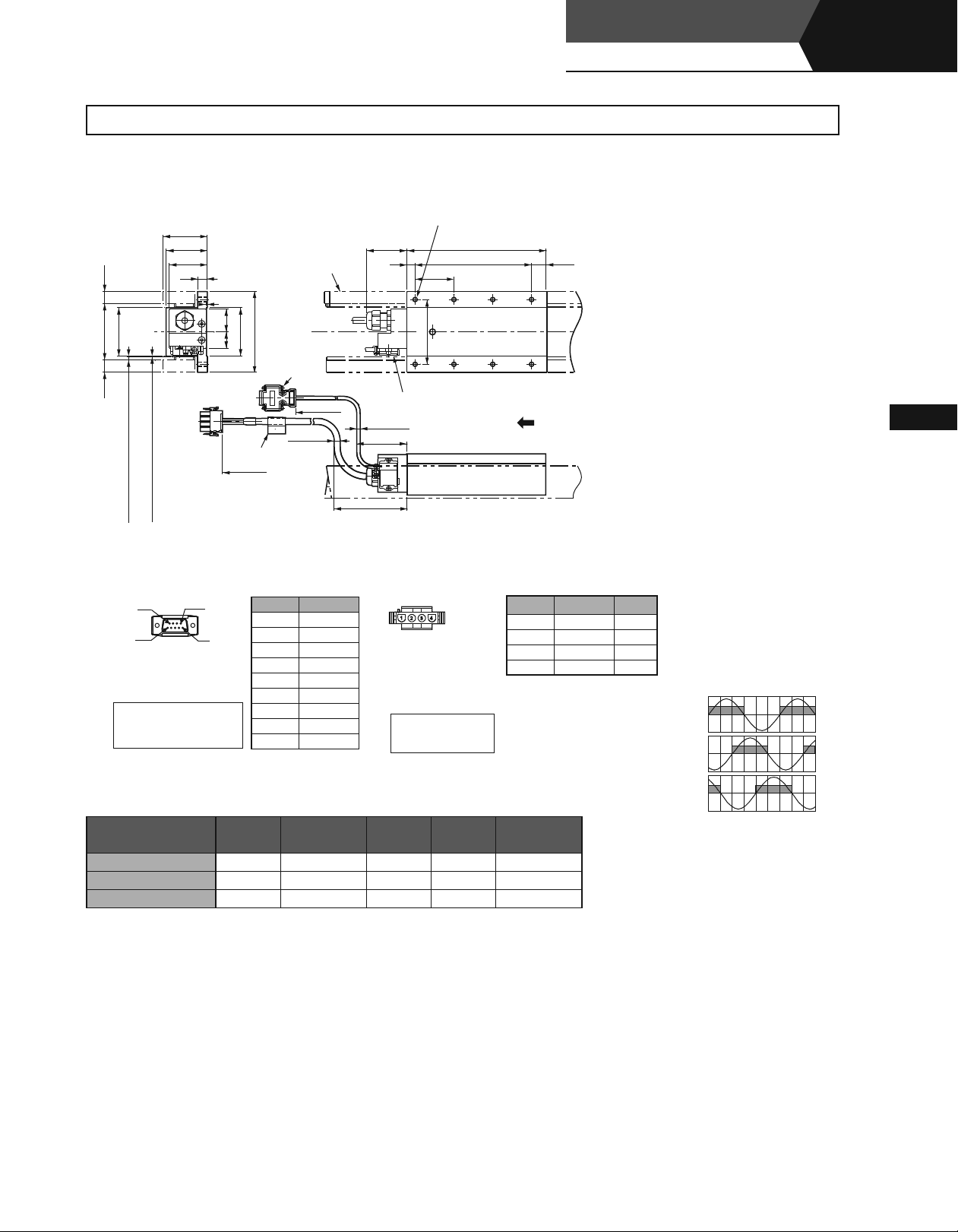
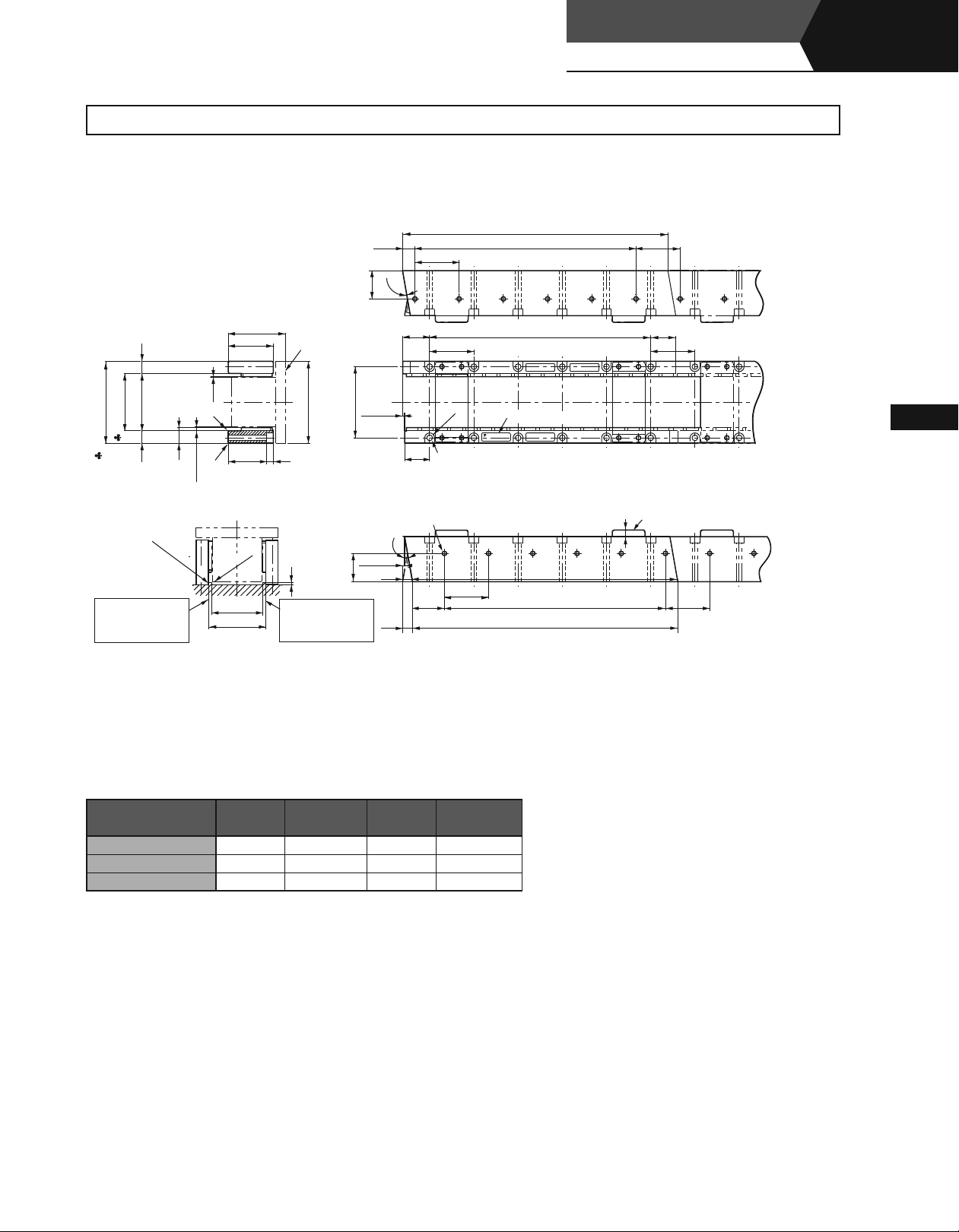
External Dimensions Units: mm
(1) Standard Type SGLTW-20SGLTW-20
Moving Coil:
3
SGLTW-20A¡¡¡A¡ (With a connector by Tyco Electronics AMP K.K.)
Linear Servomotors
SGLTW
(With T-type iron core)
Linear
(55)
51
)
15
(
)
60
70
(
)
15
(
)
With Magnet Cover
:
2
.
19
(
Hall Sensor
Connector Specifications
Pin Connector:
17
JE-
by DDK Ltd.
The Mating Connector
Socket Connector:
Stud:
47.5
12
)
)
)
With Magnet Cover
Without Magnet Cover
:
8
.
:
1
0
Without Magnet Cover
:
Gap
19
Gap
(
(
(
9
5
23090-02
(D8C)
17
13090-02
JE-
17L-002
C or
17L-002C1
6
1
(D8C
1
28
20
)
60
100
2
-Screws
4-40
#
(
Nameplate
±
50
500
Pin No. Signal
1
2 Phase U
3 Phase V
4 Phase W
50V
6 Not used
7 Not used
8 Not used
9 Not used
Magnetic Way
UNC
±
50
500
)
7.4
Dia.
+
5VDC
50
10
80
Hall Sensor
(
)
4.2
Dia.
63
Min.
90
Min.
Linear Servomotor
Connector Specifications
350779-1
Plug:
350218-3
Pin :
350547-3
350654-1
350669-1
by Tyco Electronics AMP K.K.
The Mating Connector
350780-1
Cap :
350536-3
Socket:
350550-3
6
Tapped Holes, Depth
N-M
L
L
48
The moving coil moves in the direction
indicated by the arrow when current flows
in the order of phase U, V, and W.
or
(No.1 to
)
4
(No.
or
1
2
Pin No. Signal
1 Phase U Red
2 Phase V White
3 Phase W Black
)
3
4 Ground Green
12
(
)
3
L
Linear Servomotors
Wire
Color
Hall Sensor Output Signals
When the moving coil moves in the
direction indicated by the arrow in the
figure, the relationship between the hall
sensor output signals Su, Sv, Sw and the
inverse power of each motor phase Vu,
Vv, Vw becomes as shown in the figure
below.
Vu
Su
Inverse
Power
(V)
Vv
Sv
Moving Coil Model
SGLTW-
20A170A¡ 170
20A320A¡ 315
20A460A¡ 460
L1 L2 (L3) N
×3)
144 (48
288 (48
432 (48
×6)
×9)
(16) 8 2.5
(17) 14 4.6
(18) 20 6.7
Approx. Mass
kg
Vw
0 180 360 540
Sw
Electrical Angle (˚
)
164
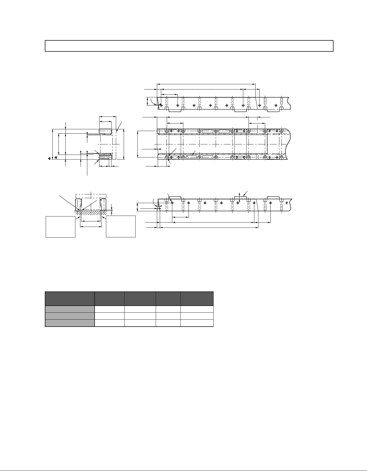
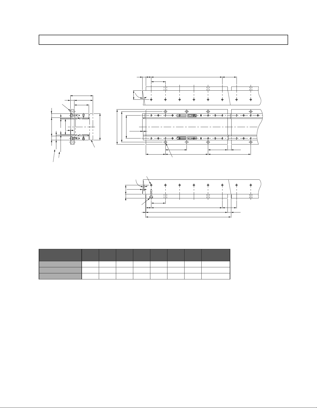
External Dimensions Units: mm
3Magnetic Way : SGLTM-20¡¡¡A¡
(
)
Max.
+
0.6
0
±
0.3
C
C
1
1
55
40
32(8
Moving Coil
)
100
(
)
3
Mount the magnetic
way so that its
corner surfaces are
flush with the inner
step.
)
15
)
Preshipment
3
(
.
0
±
Preshipment
(
1
70
±
Max.
5
*
.
71
103
15
R
0
.
5
Max.
Mount the magnetic
way so that its
corner surfaces are
flush with the inner
step.
Assembly Dimensions
)
1
(
3
.
0
±
19
1
Gap
1
R
62
*
70
0
7
13
2
.
-0.
9
.
9
27
˚
0
31.7
2
-0.
87
±
*
0.3
2.4
(
)
29.3
2
× N-M6 Screws, Depth
9.9
˚
±
*
0.3
2.4
27
0
40.3
2
-0.
(
)
9.4
1
-0.
1
L
3
-0.
2
L
)
(
54
54
(
2
L
54
6
Nameplate
R
2
× N-7 Dia. Mounting Holes (See the sectional view for the depth.
O/N
YASKAWA
TYPE:
S/N
MADE IN JAPAN
DATE
29.3
(54)
Spacers: Do not remove them until the moving coil
8
54
1
L
is mounted on the machine.
8
2
L
1
-0.
3
-0.
(54)
)
)
Notes: 1 Two magnetic ways for both ends of moving coil make one set. Spacers are mounted on magnetic ways for safety during transportation. Do not remove the spacers until the
moving coil is mounted on a machine.
2 If you have a pacemaker or any other electronic medical device, do not go near the magnetic way of the linear servomotor.
3 Two magnetic ways in a set can be connected to each other.
4 The dimensions marked with an * are the dimensions between the magnetic ways. Be sure to follow exactly the dimensions specified in the figure above. Mount magnetic ways
as shown in Assembly Dimensions. The values with a ♣ are the dimensions at preshipment.
5 Use socket headed screws of strength class 10.9 minimum for magnetic way mounting screws. Do not use stainless steel screws.
Magnetic Way Model
SGLTM-
20324A¡ 324
20540A¡ 540
20756A¡ 756
-0.1
L1
-0.3
L2 N
×5)
270 (54
486 (54
×9)
702 (54
×13)
6 3.4
10 5.7
14 7.9
Approx. Mass
kg
165
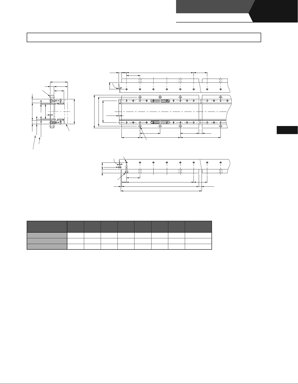
External Dimensions Units: mm
Magnetic Way with Base
3
(70)
(55)
15
Base
)
3
.
8
.
0
0
±
(
70
3
.
2
0
.
±
15 15
8
.
19
0
Gap
Includes a 0.2 thick magnet cover.
40
60
1
: SGLTM-20¡¡¡AY
)
100
(
Moving Coil
132
2
× N1-M6
Bolts, Depth
20
11.7
9
.
9
˚
27
87
116
±
0.3
2.4
2
× N1-M6 Screws, Depth
9
.
9
˚
(
±
)
0.3
2.4
2715
20
16
2.3
Linear Servomotors
Linear
SGLTW
2
54
74
8
54
L
MADE IN JAPAN
DATE
YASKAWA
TYPE:
5
L
2
× N2-10 Dia. Mounting Holes
(
See the sectional view for the depth.
TYPE:
S/N
YASKAWA
O/N
O/N
S/N
MADE IN JAPAN
DATE
74
4
L
2
L
3
L
1
-0.
1
L
3
-0.
(With T-type iron core)
(54)
(14)
(
)
162
)
(54)
(
)
11.7
Linear Servomotors
Notes: 1 If you have a pacemaker or any other electronic medical device, do not go near the magnetic way of the linear servomotor.
2 Two magnetic ways in a set can be connected to each other.
3 The characteristics of the magnetic way with base are the same as of the magnetic way without base (SGLTM-20¡¡¡A).
Magnetic Way Model
SGLTM-
L1 L2 L3 L4 L5 N1 N2
Approx. Mass
20324AY 324 270 310 162 162 6 2 5.1
Y 540 486
20540A
526 378 189 10 3 8.5
20756AY 756 702 742 594 198 14 4 12
kg
166
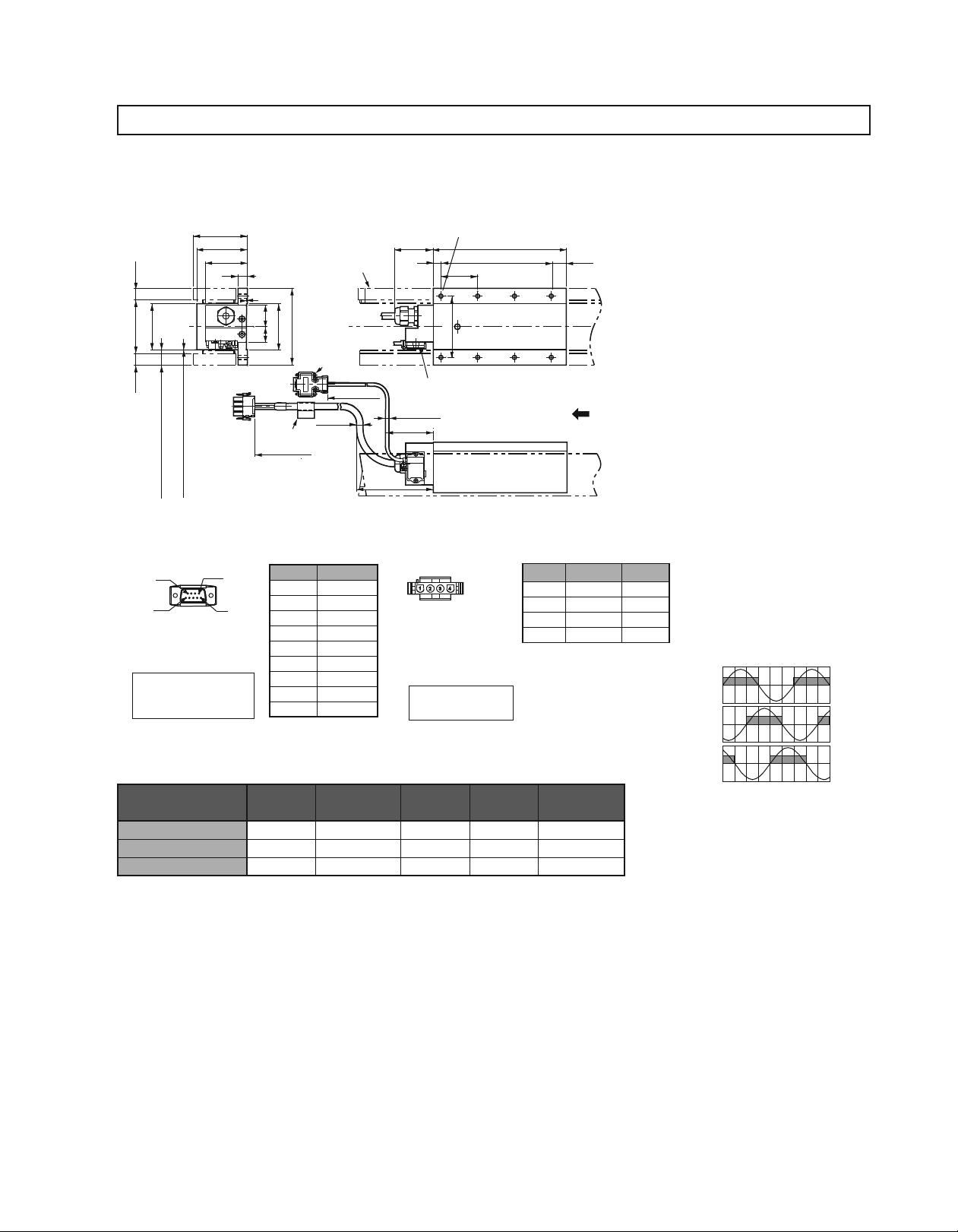
External Dimensions Units: mm
(2) Standard Type SGLTW-35ASGLTW-35A
3Moving Coil: SGLTW-35A¡¡¡A¡ (With a connector by Tyco Electronics AMP K.K.)
(70)
66
)
15
(
)
60
70
(
)
)
)
15
(
With Magnet Cover
:
Without Magnet Cover
2
.
:
19
19
(
(
Hall Sensor
Connector Specifications
9
5
Pin Connector:
17
23090-02
JE-
by DDK Ltd.
The Mating Connector
Socket Connector:
17
JE-
17L-002
Stud:
17L-002C1
55
12
)
)
With Magnet Cover
:
8
Without Magnet Cover
.
:
0
1
Gap
Gap
(
(
6
1
(D8C)
13090-02
(D8C
C or
1
28
20
Nameplate
500
)
Magnetic Way
60
100
2
-Screws
4-40
UNC
#
±
50
500
(
)
8.4
Dia.
±
50
Pin No. Signal
1
+
2 Phase U
3 Phase V
4 Phase W
50V
6 Not used
7 Not used
8 Not used
9 Not used
5VDC
50
10
Hall Sensor
(
4.2
Dia.
63
Min.
100
Min.
Linear Servomotor
Connector Specifications
Plug:
Pin :
by Tyco Electronics AMP K.K.
The Mating Connector
Cap :
Socket:
48
80
)
350779-1
350218-3
350547-3
350654-1
350669-1
350780-1
350536-3
350550-3
6
Tapped Holes, Depth
N-M
or
(No.1 to
(No.
1
L
2
L
)
3
)
4
or
12
(
)
3
L
The moving coil moves in the direction
indicated by the arrow when current flows
in the order of phase U, V, and W.
Pin No. Signal
1 Phase U Red
2 Phase V White
3 Phase W Black
4 Ground Green
Wire
Color
Hall Sensor Output Signals
When the moving coil moves in the
direction indicated by the arrow in the
figure, the relationship between the hall
sensor output signals Su, Sv, Sw and the
inverse power of each motor phase Vu,
Vv, Vw becomes as shown in the figure
below.
Inverse
Power
(V)
Vu
Su
Vv
Sv
167
Moving Coil Model
SGLTW-
35A170A¡ 170
35A320A¡ 315
35A460A¡ 460
L1 L2 (L3) N
×3)
144 (48
288 (48
432 (48
×6)
×9)
(16) 8 3.7
(17) 14 6.8
(18) 20 10
Approx. Mass
kg
Vw
0 180 360 540
Sw
Electrical Angle (˚
)
External Dimensions Units: mm
3Magnetic Way: SGLTM-35¡¡¡A¡
)
(
70
)
15
)
3
.
0
Preshipment
±
Preshipment
(
(
1
.
0
70
±
*
5
.
71
Max.
103
15
R
0
.
5
Max.
Mount the magnetic
way so that its corner
surfaces are flush with
the inner step.
3
.
0
19
±
1
Gap
Assembly Dimensions
55
)
1
(
C
1
1
C
47
Max.
1
R
6
+0.
62
0
±
*
0.3
70
Moving Coil
)
100
(
(8)
3
Mount the magnetic
way so that its corner
surfaces are flush with
the inner step.
0
15
2
-0.
5
9
.
.
9
˚
34
0
33
-0.
87
±
*
0.3
2.4
(
30.6
2
× N-M6 Screws, Depth
9.9
˚
5
±
*
0.3
2.4
.
34
39
(12)
Linear Servomotors
SGLTW
1
-0.
1
L
3
-0.
2
Nameplate
YASKAWA
TYPE:
8
L
O/N
S/N
MADE IN JAPAN
2
L
DATE
Spacers: Do not remove them until the moving
coil is mounted on the machine.
2
L
1
-0.
1
L
3
-0.
54
2
54
6
R
2
× N-7 Dia. Mounting Holes (See the sectional view for the depth.
)
54
0
2
-0.
(With T-type iron core)
(
)
54
(
)
30.6
(54)
4
(54)
Linear
)
Linear Servomotors
Notes: 1 Two magnetic ways for both ends of moving coil make one set. Spacers are mounted on magnetic ways for safety during transportation. Do not remove the spacers until the
moving coil is mounted on a machine.
2 If you have a pacemaker or any other electronic medical device, do not go near the magnetic way of the linear servomotor.
3 Two magnetic ways in a set can be connected to each other.
4 The dimensions marked with an * are the dimensions between the magnetic ways. Be sure to follow exactly the dimensions specified in the figure above. Mount magnetic ways
as shown in Assembly Dimensions. The values with a ♣ are the dimensions at preshipment.
5 Use socket headed screws of strength class 10.9 minimum for magnetic way mounting screws. Do not use stainless steel screws.
Magnetic Way Model
SGLTM-
35324A¡ 324
35540A¡ 540
35756A¡ 756
-0.1
L1
-0.3
L2 N
×5)
270 (54
486 (54
×9)
702 (54
×13)
6 4.8
10 8
14 11
Approx. Mass
kg
168
External Dimensions Units: mm
Magnetic Way with Base
3
(85)
(
15
Base
)
3
.
8
.
0
±
0
(
70
3
.
2
0
.
±
15 15
8
.
19
0
Gap
Includes a 0.2 thick magnet cover.
55
60
1
: SGLTM-35¡¡¡AY
)
70
)
100
(
Moving Coil
132
20
13
2
L
(54)
54
5
9
.
.
9
˚
34
MADE IN JAPAN
DATE
87
116
±
0.3
2.4
YASKAWA
TYPE:
5
L
74
2
× N2-10 Dia.
Mounting Holes (See the sectional view for the depth.
TYPE:
S/N
YASKAWA
O/N
O/N
S/N
DATE
MADE IN JAPAN
4
74
L
(14)
(
)
162
)
2
× N1-M6 Screws, Depth
9
.
9
˚
515
(
±
)
0.3
2.4
.
34
2
× N1-M6
Bolts, Depth
20
16
1
Notes: 1 If you have a pacemaker or any other electronic medical device, do not go near the magnetic way of the linear servomotor.
2 Two magnetic ways in a set can be connected to each other.
3 The characteristics of the magnetic way with base are the same as of the magnetic way without base (SGLTM-35¡¡¡A).
Magnetic Way Model
SGLTM-
L1 L2 L3 L4 L5 N1 N2
8
54
2
L
3
L
1
-0.
1
L
3
-0.
Approx. Mass
35324AY 324 270 310 162 162 6 2 6.4
Y 540 486
35540A
526 378 189 10 3 11
35756AY 756 702 742 594 198 14 4 15
(54)
(13)
kg
169

External Dimensions Units: mm
(3) Standard Type SGLTW-40
Moving Coil: SGLTW-40
3
(83)
)
1
.
19
(
78
75
16
¡¡¡¡B¡
Hall Sensor
Receptacle
Magnetic Way
(With an MS connector)
8
Tapped Holes, Depth
N-M
63
20
40 60
Linear Servomotors
Linear
SGLTW
16
1
L
2
L
(With T-type iron core)
(
)
3
L
)
8
.
97
111
(
)
1
.
19
(
Hall Sensor
Connector Specifications
)
)
)
)
With Magnet Cover
Without Magnet Cover
:
:
2
4
.
.
1
1
With Magnet Cover
Without Magnet Cover
:
:
3
1
.
.
Gap
Gap
25
25
(
(
(
(
9
5
Pin Connector:
17JE-23090-02 (D8C)
by DDK Ltd.
The Mating Connector
Socket Connector:
17JE-13090-02 (D8C)
Stud: 17L-002C or
17L-002C1
1
30 38
98
2
-Screws
4-40
#
150
UNC
)
Dia.
2
.
4
64
Min.
(
±
50500
O/N
S/N
W
A
YASKAWA ELECTRIC
N
V
ins.
DATE
m/s
124
The moving coil moves in the direction
indicated by the arrow when current flows
in the order of phase U, V, and W.
TYPE
Linear SERVO MOTOR
MADE IN JAPAN
Nameplate
Linear Servomotor
Connector Specifications
6
1
Pin No. Signal
1
+
2 Phase U
3 Phase V
4 Phase W
50V
6 Not used
7 Not used
8 Not used
9 Not used
5VDC
Receptacle type: MS3102A-22-22P
by DDK Ltd.
The Mating Connector
L-shaped plug type : MS3108B22-22S
Straight plug type : MS3106B22-22S
Cable clamp type : MS3057-12A
Pin No. Signal
A Phase U
B Phase V
C Phase W
D Ground
Hall Sensor Output Signals
When the moving coil moves in the
direction indicated by the arrow in the
figure, the relationship between the hall
sensor output signals Su, Sv, Sw and the
inverse power of each motor phase Vu,
Vv, Vw becomes as shown in the figure
below.
Vu
Su
Linear Servomotors
Inverse
Power
(V)
Vv
Sv
Moving Coil Model
SGLTW-
40¡400B¡ 395
L1 L2 (L3) N
360(60×6) (15)
14 15
40¡600B¡ 575 540(60 ×9) (15) 20 22
Approx. Mass
kg
Vw
0 180 360 540
Electrical Angle (˚
Sw
)
170

External Dimensions Units: mm
3Magnetic Way : SGLTM-40¡¡¡A¡
(
)
83
63
)
4
.
1
(
C
1
(15)
48
4
6
+0.
0
±
0.3
Mount the magnetic
way so that its
corner surfaces are
flush with the inner
step.
)
)
Preshipment
(
Preshipment
(
1
Max.
113
♣
153
♣
R
0
.
5
Max.
Mount the magnetic
way so that its
corner surfaces are
flush with the inner
step.
1
.
19
8
.
111
1
.
25
R
3
.
0
4
.
1
Gap
Max.
1
3
.
0
*
1
.
19
100
*
111.8
Assembly Dimensions
Moving Coil
)
150
(
2
0
15
2
-0.
5
.
6
39
°
0
37.5
2
-0.
131
0.3
1.4
)
(
36.1
×
N-M8 Screws, Depth
°
5.6
*
±
0.3
1.4
39
0
52.5
2
-0.
(
)
7.6
67
.
2
10
5
67
5
.
×
N-9 Dia.
Nameplate
YASKAWA
TYPE:
67
.
1
-0.
1
L
3
-0.
2
L
DATE
MADE IN JAPAN
S/N
O/N
2
L
(
)
67.5
TYPE:
YASKAWA
(
67.5
Mounting Holes (See the sectional view for the depth.
Spacers: Do not remove them until the moving coil
is mounted on the machine.
6
O/N
S/N
MADE IN JAPAN
5
2
L
1
-0.
1
L
3
-0.
(
(
36.1
)
67.5
)
)
O/N
YASKAWA
TYPE:
S/N
MADE I
)
Notes: 1 Two magnetic ways for both ends of moving coil make one set. Spacers are mounted on magnetic ways for safety during transportation. Do not remove the spacers until the
moving coil is mounted on a machine.
2 If you have a pacemaker or any other electronic medical device, do not go near the magnetic way of the linear servomotor.
3 Two magnetic ways in a set can be connected to each other.
4 The dimensions marked with an * are the dimensions between the magnetic ways. Be sure to follow exactly the dimensions specified in the figure above. Mount magnetic ways
as shown in Assembly Dimensions. The values with a ♣ are the dimensions at preshipment.
5 Use socket headed screws of strength class 10.9 minimum for magnetic way mounting screws. Do not use stainless steel screws.
Magnetic Way Model
SGLTM-
40405A¡ 405
40675A¡ 675
40945A¡ 945
-0.1
L1
-0.3
L2 N
337.5 (67.5
607.5 (67.5
877.5 (67.5
×5)
×9)
×13)
69
10 15
14 21
Approx. Mass
kg
171

External Dimensions Units: mm
Magnetic Way with Base
3
: SGLTM-40¡¡¡AY
Linear Servomotors
SGLTW
(With T-type iron core)
Linear
(
)
103
1
.
19
3
.
0
±
8
.
111
1
.
19
3
.
25
Base
)
2
.
1
(
3
.
0
±
2
.
1
20
90
(83)
63
1
Moving Coil
Gap
Includes a 0.2 thick magnet cover.
)
150
(
2
190
× N1-M8 Bolts, Depth
12.525
5
.
6
39
゚
170
131
±
0.3
1.4
2
× N1 - M8 Screws, Depth
(
1.4±0.3
39
5
.
6
゚
)
20
25
25
5
92.5
67.5
67.5
(
)
2
L
MADE IN JAPAN
DATE
TYPE:
S/N
YASKAWA
O/N
O/N
YASKAWA
S/N
TYPE:
DATE
MADE IN JAPAN
592
L
4
L
2
× N2 -12 Dia. Mounting Holes
(
10
See the sectional view for the depth.
67.5
(
)
17.5
)
5
.
(
202.5
)
Linear Servomotors
(
2
L
3
L
1
-0.
1
L
3
-0.
(
12.5
67.5
)
)
Notes: 1 If you have a pacemaker or any other electronic medical device, do not go near the magnetic way of the linear servomotor.
2 Two magnetic ways in a set can be connected to each other.
3 The characteristics of the magnetic way with base are the same as of the magnetic way without base (SGLTM-40¡¡¡A).
Magnetic Way Model
SGLTM-
L1 L2 L3 L4 L5 N1 N2
Approx. Mass
40405AY 405 337.5 387.5 202.5 202.5 6 2 13
Y 675 607.5
40675A
657.5 472.5 236.25 10 3 21
40945AY 945 877.5 927.5 742.5 247.5 14 4 30
kg
172

External Dimensions Units: mm
(4) Standard Type SGLTW-80
Moving Coil: SGLTW-80
3
(
)
120
)
1
.
19
(
115
75
Magnetic Way
16
¡¡¡¡B¡
Hall Sensor
Receptacle
(With an MS connector)
N-M8 Tapped Holes, Depth
63
20
6040
16
1
L
2
L
(
)
3
L
)
8
.
97
111
(
)
)
)
)
1
.
19
(
With Magnet Cover
:
2
.
With Magnet Cover
1
Without Magnet Cover
:
:
3
1
.
.
Gap
25
25
(
(
(
Hall Sensor
Connector Specifications
9
5
Pin Connector:
17JE-23090-02 (D8C)
by DDK Ltd.
The Mating Connector
Socket Connector:
17JE-13090-02 (D8C)
Stud: 17L-002C or
17L-002C1
1
38
98
150
30
)
2
-Screws
4-40
#
Without Magnet Cover
:
4
.
1
Gap
(
UNC
6
1
)
Dia.
2
64
.
4
(
±
50
500
Nameplate
Pin No. Signal
1
+
2 Phase U
3 Phase V
4 Phase W
50V
6 Not used
7 Not used
8 Not used
9 Not used
5VDC
Min.
O/N
S/N
Y
A
SKA
WA ELECTRIC
DATE
124
TYPE
Linear SERVO MOTOR
W
A
V
MADE IN JAPAN
ins.
m/s
Linear Servomotor
Connector Specifications
Receptacle type: MS3102A-22-22P
by DDK Ltd.
The Mating Connector
L-shaped plug type : MS3108B22-22S
Straight plug type : MS3106B22-22S
Cable clamp type : MS3057-12A
The moving coil moves in the direction
indicated by the arrow when current flows
in the order of phase U, V, and W.
Pin No. Signal
A Phase U
B Phase V
C Phase W
D Ground
Hall Sensor Output Signals
When the moving coil moves in the
direction indicated by the arrow in the
figure, the relationship between the hall
sensor output signals Su, Sv, Sw and the
inverse power of each motor phase Vu,
Vv, Vw becomes as shown in the figure
below.
Vu
Su
Inverse
Power
(V)
Vv
Sv
Moving Coil Model
SGLTW-
80¡400B¡ 395
L1 L2 L3 N
360(60×6) (15)
14 24
80¡600B¡ 575 540(60×9) (15) 20 35
Approx. Mass
kg
Vw
0 180 360 540
Electrical Angle (˚
Sw
)
173

Linear Servomotors
SGLTW
(With T-type iron core)
External Dimensions Units: mm
3Magnetic Way : SGLTM-80¡¡¡A¡
1
-0.
1
L
3
0
16.9
2
-0.
57
)
(
1
.
19
)
)
)
3
.
4
3
.
0
±
8
Preshipment
.
Preshipment
(
(
1
±
111
*
113
Max.
♣
153
1
.
♣
19
R
0
.
5
Max.
Mount the magnetic
way so that its
corner surfaces are
flush with the inner
step.
Notes: 1 Two magnetic ways for both ends of moving coil make one set. Spacers are mounted on magnetic ways for safety during transportation. Do not remove the spacers until the
moving coil is mounted on a machine.
2 If you have a pacemaker or any other electronic medical device, do not go near the magnetic way of the linear servomotor.
3 Two magnetic ways in a set can be connected to each other.
4 The dimensions marked with an * are the dimensions between the magnetic ways. Be sure to follow exactly the dimensions specified in the figure above. Mount magnetic ways
as shown in Assembly Dimensions. The values with a ♣ are the dimensions at preshipment.
5 Use socket headed screws of strength class 10.9 minimum for magnetic way mounting screws. Do not use stainless steel screws.
0
.
±
1
(
4
.
1
Gap
1
.
25
Max.
1
R
+0.
100
*
111.8
Assembly Dimensions
120
100
Moving Coil
)
C
1
1
85
C
(
(15)
2
× N1-M8 Screws, Depth
4
6
0
±
0.3
Mount the magnetic
way so that its
corner surfaces are
flush with the inner
step.
150
39.4
-0.
*
1.5
131
(
37.9
5.6
*
±
0.3
1.5
57
50.6
(
11.3
0
±
°
0
-0.
5
.
6
2
0.3
)
2
)
°
67
5
.
75
33
.
7
R
×
2
N2-9 Dia. Mounting Holes (See the sectional view for the depth.
Nameplate
10
O/N
YASKAWA
S/N
TYPE:
MADE IN JAPAN
67
5
.
-0.
2
L
DATE
3
L
DATE
2
L
1
-0.
1
L
3
-0.
(
)
67.5
MADE IN JAPAN
TYPE:
S/N
YASKAWA
O/N
(
)
37.9
(
)
67.5
O/N
S/N
MADE IN JAPAN
)
Spacers: Do not remove them until the moving coil
6
is mounted on the machine.
YASKAWA
TYPE:
(
)
67.5
Linear
Linear Servomotors
Magnetic Way Model
SGLTM-
80405A¡ 405
80675A¡ 675
80945A¡ 945
-0.1
L1
-0.3
L2 L3 N1 N2
337.5(67.5
×5)
607.5(67.5×9)
877.5(67.5×13)
337.5(33.75
607.5(33.75
887.5(33.75
×
10)
×
18)
×
26)
611 14
10 19 24
14 27 34
Approx. Mass
kg
174

External Dimensions Units: mm
Magnetic Way with Base
3
20
Base
1
.
)
3
2
.
.
0
1
±
(
8
90
.
111
119
.
19
1
3
.
0
3
.
±
2
25
.
1
: SGLTM-80¡¡¡AY
(
)
140
(
)
120
100
Moving Coil
)
150
(
190
170
131
1.5
(
)
22514.4
67.5
33.75
5
.
57
6
゚
±
0.3
L
MADE IN JAPAN
DATE
TYPE:
S/N
YASKAWA
O/N
2
× N2 - 12 Dia. Mounting Holes
(
See the sectional view for the depth.
O/N
YASKAWA
S/N
TYPE:
DATE
MADE IN JAPAN
5
L
492.5
L
67.5
)
(
)
(
202.5
)
17.5
92
5
.
2
Gap
× N1-M8 Screws, Depth
Includes a 0.2 thick magnet cover.
2
× N3-M8 Bolts, Depth
Notes: 1 If you have a pacemaker or any other electronic medical device, do not go near the magnetic way of the linear servomotor.
2 Two magnetic ways in a set can be connected to each other.
3 The characteristics of the magnetic way with base are the same as of the magnetic way without base (SGLTM-80¡¡¡A).
Magnetic Way Model
SGLTM-
L1 L2 L3 L4 L5 N1 N2 N3
10
(
1.5±0.3
20 57
5
.
6
゚
)
33.75
67
5
25
3
1
.
.
25
2
L
3
L
1
-0.
1
L
3
-0.
80405AY 405 337.5 387.5 202.5 202.5 6 2 11 18
Y 675 607.5
80675A
657.5 472.5 236.25 10 3 19 31
80945AY 945 877.5 927.5 742.5 247.5 14 4 27 43
Approx. Mass
kg
(
14.4
(
67.5
)
)
175

Linear Servomotors
SGLTW
External Dimensions Units: mm
(5) High-efficiency Type SGLTW-35A¡¡¡H¡
3Moving Coil: SGLTW-35A¡¡¡H¡ (With a connector by Tyco Electronics AMP K.K.)
(With T-type iron core)
Linear
(70)
28
30
)
:Without Magnet Cover
0
.
1
Gap
(
1
(D8C
66
62.5
Magnetic Way
12
S/N
YASKAWA ELECTRICMADE IN JAPAN
W
AV
DATE
ins.
m/sN
0
±
60
120
1
.
1
Linear SERVO MOTOR
TYPE
O/N
Nameplate
2
-Screws
4-40
UNC
#
Cable
,
20276
UL
)
28
AWG
Pin No. Signal
1 +5VDC
2 Phase U
3 Phase V
4 Phase W
50V
6 Not used
7 Not used
8 Not used
9 Not used
L1 L2 (L3) N
144 (48
288 (48
1
.
0
)
±
15
20
05
.
)(
0
±
90
(
80
30
)
)
)
)(
15
:With Magnet Cover
:With Magnet Cover
8
2
.
.
:Without Magnet Cover
0
19
(
19
(
Gap
(
Hall Sensor
Connector Specifications
96
5
Pin Connector:
17
23090-02
JE-
by DDK Ltd.
The Mating Connector
Socket Connector:
Stud:
17
13090-02
JE-
17L-002
17L-002C1
(D8C)
C or
Moving Coil Model
SGLTW-
35A170H¡ 170
35A320H¡ 315
Hall Sensor
)
Dia.
2
.
4
(
±
50
500
×3)
×6)
N-M6 Screws, Depth
1
30
10
±
0.15
48
20
15
.
0
±
L
2
L
100
Protective Tube
The moving coil moves in the direction
indicated by the arrow when current flows
50
±
in the order of phase U, V, and W.
500
35
43
63
Min.
Lead Specifications of Moving Coil
・
If this cable is bent repetitively, the cable
will disconnect.
Phase V
Phase W
(
View from Top of Moving Coil
Name Color Code
Phase U
Phase V V
Phase W W
Ground Green – 2 mm
Phase U
Ground
)
U
Black
Approx. Mass
(16) 8 4.7
(17) 14 8.8
kg
Wire
Size
2 mm
12
(
)
3
L
Linear Servomotors
Hall Sensor Output Signals
When the moving coil moves in the
direction indicated by the arrow in the
figure, the relationship between the hall
sensor output signals Su, Sv, Sw and the
inverse power of each motor phase Vu,
Vv, Vw becomes as shown in the figure
below.
Vu
Su
Inverse
2
Power
Vv
(V)
2
Vw
Sv
Sw
0 180 360 540
Electrical Angle (˚
)
176

External Dimensions Units: mm
Moving Coil: SGLTW-35D
3
¡¡¡H¡
(70)
28
30
)
66
62.5
12
Linear SERVO MOTOR
TYPE
O/N
S/N
YASKAWA ELECTRICMADE IN JAPAN
W
AV
DATE
ins.
m/sN
Nameplate
1
.
1
0
±
60
120
1
.
0
)
±
15
20
05
.
0
)(
±
90
(
80
30
)(
)
)
15
)
500
2
-Screws
4-40
#
20276
,AWG
Pin No. Signal
UNC
28
1
+
2 Phase U
3 Phase V
4 Phase W
50V
6 Not used
7 Not used
8 Not used
9 Not used
:With Magnet Cover
2
.
19
(
Hall Sensor
Connector Specifications
:Without Magnet Cover
19
(
8
.
0
Gap
(
0
.
1
Gap
(
:Without Magnet Cover
:With Magnet Cover
96
5
Pin Connector:
17JE-23090-02 (D8C)
by DDK Ltd.
The Mating Connector
Socket Connector:
17JE-13090-02 (D8C)
Stud: 17L-002C or
17L-002C1
1
Cable
UL
D (With a connector by Interconnectron GmbH)
N-M6 Screws, Depth
Magnetic Way
Hall Sensor
±
50
)
Dia.
2
.
4
(
500±50
5VDC
30
10
48±0.15
20
15
.
0
±
100
Protective tube
35
43
63
Min.
Linear Servomotor
Connector Specifications
6
5
1
4
Extension : ARRA06AMRPN182
Pin : 021.279.1020
by Interconnectron GmbH
The Mating Connector
Plug : APRA06BFRDN170
Socket : 020.105.1020
2
1
L
2
L
Pin No. Signal
1 Phase U
2 Phase V
4 Phase W
5 Not used
6 Not used
12
(
)
3
L
The moving coil moves in the direction
indicated by the arrow when current flows
in the order of phase U, V, and W.
Hall Sensor Output Signals
When the moving coil moves in the
direction indicated by the arrow in the
figure, the relationship between the hall
sensor output signals Su, Sv, Sw and the
inverse power of each motor phase Vu,
Vv, Vw becomes as shown in the figure
below.
Ground
Vu
Su
Inverse
Power
(V)
Vv
Sv
177
Moving Coil Model
SGLTW-
35D170H¡D
L1 L2 (L3) N
170 144(48× 3)
(16) 8 4.7
Approx. Mass
35D320H¡D 315 288(48×6) (17) 14 8.8
Vw
0 180 360 540
kg
Electrical Angle (˚
Sw
)

External Dimensions Units: mm
3Magnetic Way: SGLTM-35¡¡¡H¡
Linear Servomotors
Linear
SGLTW
1
-0.
3
-0.
1
0
2
-0.
54
9
5
.
.
9
˚
34
L
215
L
(With T-type iron core)
(54)
1
.
0
±
)
15
)
3
.
0
±
Preshipment
(
Preshipment
(
90
1
*
±
5
.
Max.
91
123
1
.
0
±
15
)
8
.
0
(
3
1
.
.
0
0
±
±
8
2
.
.
0
4
(70)
55
Moving Coil
0
33
2
-0.
2
L
54
MADE IN JAPAN DATE
TYPE:
S/N
YASKAWA
O/N
(
30.6
(54)
)
)
±
3
0
.
*
4
2
107
.
R
(
)
2
30.6
120
C
1
1
C
47
(
(8)
Model
Nameplate
6
O/N
YASKAWA
S/N
TYPE:
MADE IN JAPAN DATE
× N-7 Dia. Mounting Holes (See the sectional view for the depth.
)
Gap
0.2
6
+0.
0
±
0.3
90
thick magnet cover.
N-M6 Screws, Depth 8
2
×
3
Mount the magnetic
way so that its corner
surfaces are flush with
the inner step.
Spacer: Do not remove them until the moving
)
coil is mounted on the machine.
4
9
.
9
˚
5
±
*
0.3
2.4
.
34
54
0
39
2
-0.
(12)
2
L
1
-0.
1
L
3
-0.
(
(54)
R
0
.
5
Max.
Mount the magnetic
way so that its corner
surfaces are flush with
the inner step.
Includes a
Max.
1
R
82
*
Assembly Dimensions
Notes: 1 Two magnetic ways for both ends of moving coil make one set. Spacers are mounted on magnetic ways for safety during transportation. Do not remove the spacers until the
moving coil is mounted on a machine.
2 If you have a pacemaker or any other electronic medical device, do not go near the magnetic way of the linear servomotor.
3 Two magnetic ways in a set can be connected to each other.
4 The dimensions marked with an * are the dimensions between the magnetic ways. Be sure to follow exactly the dimensions specified in the figure above. Mount magnetic ways
as shown in Assembly Dimensions. The values with a ♣ are the dimensions at preshipment.
5 Use socket headed screws of strength class 10.9 minimum for magnetic way mounting screws. Do not use stainless steel screws.
Linear Servomotors
Magnetic Way Model
SGLTM-
35324H¡ 324
35540H¡ 540
35756H¡ 756
-0.1
L1
-0.3
L2 N
×5)
270 (54
486 (54
×9)
702 (54
×13)
10 8
14 11
Approx. Mass
kg
6 4.8
178

External Dimensions Units: mm
(6) High-efficiency Type SGLTW-50
3Moving Coil: SGLTW-50A¡¡¡H¡ (With a connector by Tyco Electronics AMP K.K.)
)
1
.
1
.
0
±
19
(
20
05
)
.
0
±
90
(
80
)
1
.
19
(
Hall Sensor
Connector Specifications
Pin Connector:
17
JE-
by DDK Ltd.
The Mating Connector
Socket Connector:
Stud:
2830
)
)
: With Magnet Cover
3
.
23
(
)
)
: With Magnet Cover
: Without Magnet Cover
: Without Magnet Cover
8
0
1
.
.
.
0
1
23
(
Gap
Gap
(
(
96
(D8C)
13090-02
C or
1
(D8C
5
23090-02
17
JE-
17L-002
17L-002C1
Moving Coil Model
SGLTW-
50A170H¡ 170
50A320□ 315
(85)
81
5
62
.
12
Linear SERVO MOTOR
TYPE
O/N
S/N
YASKAWA ELECTRICMADE IN JAPAN
W
AV
DATE
ins.
m/sN
Nameplate
2
-Screws
4-40
#
1
UNC
Magnetic Way
)
1
.
4
(
1
.
0
±
60
120
Hall Sensor
±
50
500
)
Dia.
2
.
4
(
Hall Sensor
End Connector
Cable
,
UL
)
20276
28
AWG
Pin No. Signal
1 +5VDC
2 Phase U
3 Phase V
4 Phase W
50V
6 Not used
7 Not used
8 Not used
9 Not used
L1 L2 (L3) N
×3)
144 (48
288 (48
×6)
N-M6 Screws, Depth
30
10
±
0.15
48
20
15
.
0
±
1
L
2
L
100
Protective Tube
50
±
The moving coil moves in the direction
indicated by the arrow when current flows
in the order of phase U, V, and W.
500
35
43
63
Min.
Lead Specifications of Moving Coil
• If this cable is bent repetitively, the cable
will disconnect.
Phase V
Phase W
(
View from Top of Moving Coil
Name Color Code
Phase U
Phase V V
Phase W W
Ground Green – 2 mm
Phase U
Ground
U
Black
Approx. Mass
(16) 8 6
(17) 14 11
kg
Wire
Size
2 mm
12
(
)
3
L
Hall Sensor Output Signals
When the moving coil moves in the
direction indicated by the arrow in the
figure, the relationship between the hall
sensor output signals Su, Sv, Sw and the
inverse power of each motor phase Vu,
Vv, Vw becomes as shown in the figure
below.
)
Vu
Su
Inverse
Power
2
2
Vv
(V)
Vw
0 180 360 540
Electrical Angle (˚
Sv
Sw
)
179

External Dimensions Units: mm
Linear Servomotors
SGLTW
(With T-type iron core)
Linear
Moving Coil: SGLTW-50D
3
1
.
)
0
1
.
±
19
20
(
05
.
0
)
±
90
(
80
)
1
.
19
(
Hall Sensor
Connector Specifications
)
:With Magnet Cover
3
.
23
(
)
:Without Magnet Cover
1
.
23
(
2830
)
)
:With Magnet Cover
:Without Magnet Cover
0
8
.
.
1
0
Gap
(
Gap
(
96
5
Pin Connector:
17JE-23090-02 (D8C)
by DDK Ltd.
The Mating Connector
Socket Connector:
17JE-13090-02 (D8C)
Stud: 17L-002C or
17L-002C1
1
(85)
81
5
62
.
12
Linear SERVO MOTOR
TYPE
O/N
S/N
YASKAWA ELECTRICMADE IN JAPAN
W
AV
DATE
ins.
m/sN
Nameplate
2
-Screws
4-40
#
Cable
20276
UL
¡¡¡H¡
)
1
.
4
(
1
.
1
0
±
60
120
500
UNC
500±50
28
,AWG
Pin No. Signal
1
+
2 Phase U
3 Phase V
4 Phase W
50V
6 Not used
7 Not used
8 Not used
9 Not used
5VDC
D (With a connector by Interconnectron GmbH)
N-M6 Screws, Depth
1
L
2
L
The moving coil moves in the direction
indicated by the arrow when current flows
in the order of phase U, V, and W.
Pin No. Signal
1 Phase U
2 Phase V
4 Phase W
5 Not used
6 Not used
Magnetic Way
Hall Sensor
±
50
)
Dia.
2
.
4
(
30
10
48±0.15
20
15
.
0
±
100
Protective tube
35
43
63
Min.
Linear Servomotor
Connector Specifications
6
5
1
4
Extension : ARRA06AMRPN182
Pin : 021.279.1020
by Interconnectron GmbH
The Mating Connector
Plug : APRA06BFRDN170
Socket : 020.105.1020
2
12
Ground
(
)
3
L
Hall Sensor Output Signals
When the moving coil moves in the
direction indicated by the arrow in the
figure, the relationship between the hall
sensor output signals Su, Sv, Sw and the
inverse power of each motor phase Vu,
Vv, Vw becomes as shown in the figure
below.
Vu
Su
Inverse
Power
(V)
Vv
Sv
Linear Servomotors
Moving Coil Model
SGLTW-
50D170H¡D
L1 L2 (L3) N
170 144(48×3)
(16) 8 6
Approx. Mass
50D320H¡D 315 288(48×6) (17) 14 11
Vw
0 180 360 540
kg
Electrical Angle (˚
Sw
)
180

External Dimensions Units: mm
3Magnetic Way: SGLTM-50¡¡¡H¡
1
.
0
±
1
.
)
19
)
3
.
0
±
Preshipment
(
Preshipment
90
(
*
1
±
5
.
Max.
91
131
1
.
0
±
1
.
19
)
8
.
0
(
1
3
.
.
0
0
±
±
2
8
.
.
4
0
Gap
Includes a
(85)
70
C
1
1
C
62
0.2
thick magnet cover.
(8)
0
9
2
-0.
42
0
27
2
)
1
.
4
-0.
)(
120
(
112
Moving Coil
1
-0.
1
L
3
-0.
2
L
54
2
L
54
MADE IN JAPAN DATE
S/N
O/N
Model
Nameplate
Dia.
12
2
× N-7 Dia. Mounting Holes
(
See the sectional view for the depth.
O/N
YASKAWA
S/N
MADE IN JAPAN DATE
TYPE:
)
(
54
(27)
(54)
TYPE:
YASKAWA
)
Spacers: Do not remove them until the moving
coil is mounted on the machine.
)
4
(
R
0
.
5
Max.
Mount the magnetic
way so that its corner
surfaces are flush with
the inner step.
R
Max.
1
*
3
2
× N-M6 Screws, Depth
6
+0.
82
0
±
0.3
90
Mount the magnetic
way so that its corner
surfaces are flush with
the inner step.
42
8
54
0
45
2
-0.
2
L
1
-0.
1
3
-0.
L
(54)
Assembly Dimensions
Notes: 1 Two magnetic ways for both ends of moving coil make one set. Spacers are mounted on magnetic ways for safety during transportation. Do not remove the spacers until the
moving coil is mounted on a machine.
2 If you have a pacemaker or any other electronic medical device, do not go near the magnetic way of the linear servomotor.
3 Two magnetic ways in a set can be connected to each other.
4 The dimensions marked with an * are the dimensions between the magnetic ways. Be sure to follow exactly the dimensions specified in the figure above. Mount magnetic ways
as shown in Assembly Dimensions. The values with a ♣ are the dimensions at preshipment.
5 Use socket headed screws of strength class 10.9 minimum for magnetic way mounting screws. Do not use stainless steel screws.
Magnetic Way Model
SGLTM-
50324H¡ 324
50540H¡ 540
50756H¡ 756
-0.1
L1
-0.3
L2 N
×5)
270 (54
486 (54
×9)
702 (54
×13)
68
10 13
14 18
Approx. Mass
kg
181
 Loading...