

Page 1
<
"
Before
initial
operation
rte
;
read
these
instructions
s'
thoroughly
and
retain
for
future
reference
688-284
ETL
Testing
Laboratories
Certification
When
properly
installed,
operated
and
maintained,
this
equipment
will
provide
a
lifetime
of
service
.
It
is
mandatory
that
the
person
who
operates,
inspects,
or
maintains
this
equipment
thoroughly
read
and understand
this
manual,
before
proceeding
.
This
manual
applies
to
VS-616GII
Model
CIMR-H18
.5G2,
-H22G2,
-H30G2,
-H37G2,
-H45G2
.
The
VS-616GII
Drive
is
an
AC
variable
speed
drive
system
for
high-precision
variable
speed
applications
.
It
basically
consists
of a
three-phase
squirrel-
cage
induction
motor,
a
VS-616GII
controller
(VS-616GII),an
operator
control
station,
and
optional
control
units
.
This
manual
primarily
describes
VS-
616GII,
but
contains
basic
information
for
operator
control station
as
well
.
For
details
of the
operation
of
individual
units,
refer
to
their
respective
man-
uals
.
il -1
<-'r'
'
--
.RaY
Tr
r"~rc:'P
-r
"
16GII
Type
CINIR-H22G2
Page 2
CONTENTS
Page
1
.
RECEIVING
.
. . ...
. . .
. . . .
. . .
. . .
. . .
. . .
. . .
. . . .
. . .
.
.
. . . .
. . .
. .
. . .
. . . .
. . . .
. . .
. . .
. .
. . .
. .
. . . .
. .
. . . .
. .
.
. . .
. .
. . . .
. . .
. . . .
. .
. . . . .
. .
. . .
. . .
. . . .
. .
. . . . .
3
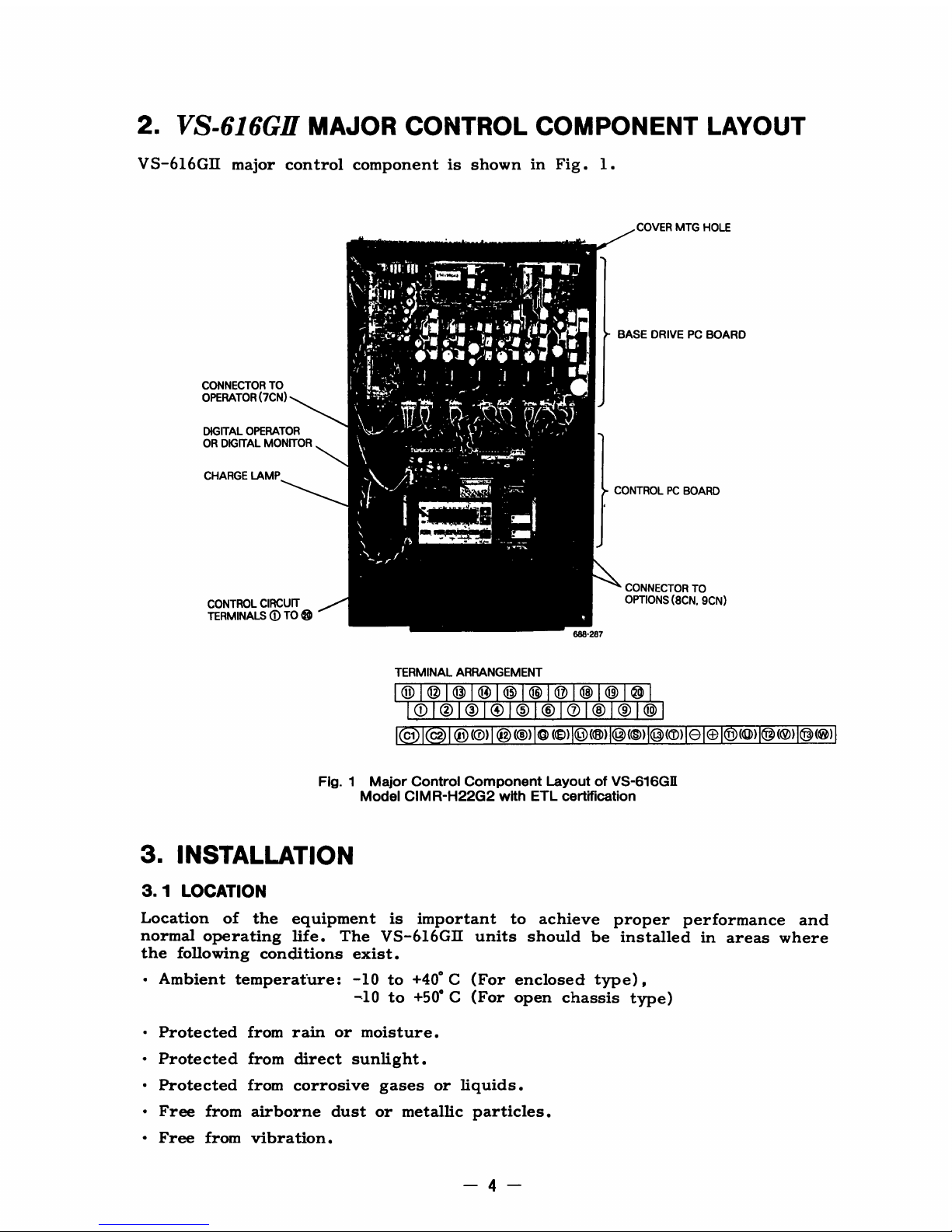
2.VS-616GI1
MAJOR
CONTROL
COMPONENT
LAYOUT
. .
. . .
. . .
. .
. . ...
. .
. . .
. .
. . . .
. . .
. . . .
. .
. . . .
. .
. . .
. . .
. . . . . ..4
3
.
INSTALLATION
.
. . . .
. . .
. . ..... . .
. . .
. . . . .
. .
. . . .
.
. .
. . .
. .
. . . .
. .
. . . . .
. . .
. . .
. .
. . . .
. .
. . .
. .
. . . . .
. .
. . .
. .
. . .
.
. . .
. . .
. .
. . . . .
. .
. . . .
. .
. . . .
. .
. . . . .
. ..4
3.1LOCATION
.
. . .
. . .
. . . .
. . .
. . .
. . .
. .
.
.
. .
. . . . .
. .
. . . . .
. .
. . .
. .
. . . .
. .
. . . . .
. .
. . . .
. .
. . . .
. .
. . .
. .
.
. .
. .
. . . . .
. .
. . .
. . .
. . . .
. .
. . . .
. .
. . . .
. . .
. . .
. . .
. . . .
. . ..4
3
.2
POSITIONING
.
. . .
. . . .
. . .
. .
.
. . .
. . .
. . .
. . . .
. . .
. . . .
. . .
. . .
. .
. . . .
. .
. . .
. . . .
. . .
. . .
. . . . . . . . ... . . .
. .
. . . . .
.
. . . .
. . .
. . .
. .
. . . . .
. .
. . . ..... . .
. .
. . . .
.
. . ..5
3.3MOUNTING
DIMENSIONS
.
. .
. . . .
.
. .
. . . .
. . .
. . . ... . . .
. . .
. . .
. . . .
. . .
. .
. . .
. .
. . . .
. .
. . .
. . .
...
.
. .
. . .
. . .
. . . .
. .
. . ...
. .
. . .
. .
. . . . .
. .
. . . . .
. .
. .
5
4
.
WIRING
.
. .
. . .
. .
. . .
. . .
. . .
. . ...
. .
. .
.
. . .
. ...
. . . .
. . .
. . .
. . .
. . .
. .
. . . .
. .
. . . . .
. .
. . .
. . .
. . .
. .
. . .
. . . ...
.
. .
. . .
. . .
. . . .
. .
. . .
. .
. . . . .
. .
. . . .
. . .
. . .
. . .
. . . . .
. .
g
4
.1
INTERCONNECTIONS
.
.
. . .
. . .
. .
. . . . .
. . . .
. . .
. .
. . .
. .
. . . .
. . .
. . . .
. . .
. . .
. .
. . . .
. .
. . . ... . . . ... . . .
. .
. . . .
. .
. . . .
. .
. . . . .
. .
. . .
. . .
. . . .
. .
. . . . .
. ..6
4.2MOLDED-CASE
CIRCUIT
BREAKER
(MCCB)
AND
POWER
SUPPLY
MAGNETIC
CONTACTOR
(MC)
. ... . . .
. .
. . . .
. .
. . .
. .
. . .
. .
. . . . .
. .
. . .
. . .
. . .
. .
. . . . .
. .
. . . ..... . .
. . .
. . . .
. . ..8
4.3SURGE
ABSORBER
.
. . .
. . .
. . .
. . .
. . . . .
. .
. . .
. ... .
. ... . . .
. . .
. . . .
. . .
. . .
. . .
. . . .
. ..... .
. . .
. .
. . . . ... . .
. . .
. . .
. . .
. .
..... . . .
. .
. . . . .
. .
. . . . .
. . ..8
4.4WIRING
INSTRUCTIONS
.
. .
. . .
. . .
. . .
. . . .
. . .
. . .
. .
. . ...
. .
. ...
. .
. .
. .
. .
. . . . . . . ..... . .
. . .
. . . .
. .
. . . .
. .
. . .
. . .
. . .
. ... . . .
. .
. . . . .
. .
. . . . .
. .
. .
9
4.4.1
Control
Circuit
.
. . .
. . .
. . .
. . .
. . .
. . .
. . . .
. .
. . . .
. . .
. . .
. .
. . .
. ... . . .
. .
. . . . .
. .
. . .
. .
. . .
. . .
. . .
. . .
. . . .
. .
. . .
. .
. . . .
. . .
. . .
. .
.
. . . .
. .
. . .
. . .
. . . . ..... .
4
.4.2Main
Circuit
Input/Output
.
.
. . . .
. . .
. . . .
. . .
. . .
. .
. . .
. . .
. . .
. . .
. . . . .
. .
.
. .
. .
. . .
. . .
. . .
. .
. . . .
. . .
. . .
. .
. . . .
. .
. . . .
. .
. . .
. .
. .
. . .
. .
. . . . .
. .
. . . .9
4.4.3
Grounding
...
. .
. . . . .
. .
. . . .
. . .
. . .
. .
. . . .
. . .
. . .
. . .
. . . .
. .
. . .
. .
. . . . .
. .
. . . . .
.
. . . ... . . .
. .
. . . .
. .
. . . . .
. .
. . .
. .
. . . ... . . . .
. .
. . . .
. . .
. .
.
. .
. . . . .
. .
. . .
.10
5.TEST
RUN
.
.
.
. . .
. .
. . . . .
. .
. . . .
. . .
. . .
. .
. . . . .
. .
. . . .
. . .
. . .
. .
. . .
. .
. . . . .
. .
. . . . .
. .
. . .
. .
. . .
. . .
. . .
. .
. . . . .
.
.
. . .
. .
. . . .
. .
. . . .
. .
. . . . .
. .
. . .
. .
. . . . ... . . .
11
5.1CHECKS
BEFORE
TEST
RUN
.
. .
. .
. . . .
. . .
. . .
. .
. . .
. .
. . . . .
. .
. . ..... . . .
. .
. . .
. . .
. . .
. .
. . . ...
. . . .
. .
. . .
. .
. . . . .
. .
. . . .
. . .
. . .
. .
. . . . .
. .
. . .
.11
5.2SIMPLE
OPERATION
USING
DIGITAL
OPERATOR
. . .
. .
. . . .
. .
. . ... . . . .
. .
. . .
. . .
. . . .
. .
. . .
. .
. . . .
. . .
. . .
. . .
. . . .
. .
. . . . .
. .
. . .
.11
5.2
. 1
Set
and
Operate
Frequency
Command
.
.
. . .
. .
. . . . .
. .
. . .
. . .
. . .
. .
. . . ... . . . .
. .
. ... .
. . . . ... . . .
. .
. . . .
. . .
. . . .
. .
. . . .
. .
. . . .
. . .
. . .
.12
5.2.2
Monitor
FunctionofDigital
Operator
.
. . . .
. . .
. .
. . . .
. . .
. . .
. .
. . . . ... . .
. .
. . . . . ... . .
. .
. . . . .
. .
. . .
. .
. . . . .
. .
. . . .
. .
. . . .
. .
. . . . .
. .
. .
.
.13
5.3ADJUSTMENT
AND
SETTING
.
.
. .
. . . .
. .
. . . .
. .
. . .
. .
. . . .
. . .
. . .
. .
. . . .
. .
. . .
. .
. . . . . ... . .
. .
. . . . ...
. . .
. .
. . . . .
. .
. . . .
. .
. . . .
. .
. . . .
. .
. . . .
.14
6.OPERATION
AT
LOAD
.
. . ... . . . .
. .
. . . . .
. .
. . .
. .
. . . .
. .
. . . ..... . . .
.
. . .
. .
. . . .
. .
. . .
. . .
. . . .
. .
. . .
. .
. . . . .
. .
. . .
. .
. . . . .
. .
. . .
. .
. . . . .
. .
. . . . .
.
17
7.MAINTENANCE
.
. . . . ... . . .
. . .
. . ... . . ... . . . . .
. .
. . .
. .
. . . .
. .
. . .
. . .
. .
. .
. .
. . .
. . .
. . .
. .
. . . ... . . . .
. .
. . . ... . .
. .
. . . . .
. .
. . . .
.
. .
. . . ... . . . .
. ... . . .
.18
8.FAILURE
INDICATION
AND
DETAILS
.
. .
.
. . .
. . .
. . . .
. .
. . . .
. .
. . ... . . .
. .
. . . . ... . .
. . .
. . . .
. .
. . .
. .
. . . . .
. .
. . ... . . . .
. . .
. . .
. . .
. .
.19
8.1DISPLAYING
THE
SEQUENCE
OF
FAILURE
OCCURRENCE
. .
. . . .
. .
. . .
. . .
. . . .
. .
. . .
. .
. . . . .
. .
. . .
. .
. . . .
. .
. . . .
. . .
. . . .
20
8.2
STORAGE
FUNCTION
AT
POWER
FAILURE
. ... . . ... . . . ... . . ... . . ... . . . .
. .
. . .
. .
. . . .
. .
. . . ... . . .
. . .
. . . .
. .
. . . .
. .
. . . .
. .
. . . .
.
21
9
.
TROUBLESHOOTING
.
.
. .
. . .
. . .
. . .
.
. .
. . . .
. .
. . . ... . . ... . . . .
. .
. . . ... . . . ... . .
. .
. . . .
. .
. . . .
. .
. . .
. .
. . . .
. .
. . . ..... . .
. .
. . . . . . . . . .
. .
. . . .
.22
9
.1
TROUBLESHOOTING
FOR
MOTOR
SYMPTOM
. .
. .
. . . ... . .
. . .
. . .
. .
. . .
. .
. . . .
. . .
. . .
. .
. . . ... . . .
. .
. . . . ... . . .
. .
. . . .
. .
. . . .
. .
.
22
APPENDIX
1
STANDARD
SPECIFICATIONS.. .
. . .
. .
. . ..... . . .
. .
. . .
. .
. . . . . . . . .
. .
. . .
. . .
. . . ... . .
. .
. . . . .
. .
. . ... . . . . ... . . .
. . .
. . . .
. .
.24
APPENDIX2
TERMINAL
FUNCTIONS
.
. . .
.
.
. . .
. .
. . .
. . .
. . .
. .
. . . .
. .
. . . .
. .
. . ... . . . ... . .
. . .
. . . . ... . .
. .
. . . .
. .
. . . .
. .
. . . .
. .
. . . .
. . .
. . .
. . .
.
25
A2-1Terminals
of
Main
Circuit
.
. .
. .
. . .
. ...
. . .
. .
. . .
. . .
. . .
. . .
. . .
. .
. . . .
. .
. . . ... . .
. .
. . . .
. .
. . .
. . .
. . . .
.
.
. . .
. .
. . . .
. .
. . . .
. .
. . . .
. .
. . . ... . . . .
. .
. .
25
A2-2
TerminalsofControl
Circuit
.
. . . .
. . .
. . .
. ...
.
. .
. . . .
. .
. . .
. . .
. . . .
. .
. . .
. .
. . .
. .
. . . .
. .
. . .
. .
. . . .
. . .
. . .
. .
. . .
. . .
. . . ... . . . .
. .
. . .
. .
. . . . . ... .
25
APPENDIX
3INTERNAL
CIRCUIT
AND
INTERCONNECTION
DIAGRAMS
. ... . . .
. .
. . .
. . .
. . . ... . . . ... ...
. .
. . ... . . . .
28
A3-1
With Braking
Unit
and
Braking
Resistor
Unit
. .
. . .
. . . .
. . . .
. .
. . . .
. .
. . .
. .
. . .
. .
. . . .
. . .
. . .
. .
. . . .
. .
. . .
. . .
. . . .
. .
. . .
. . .
. . . .
. .
. . . . . .
.28
A3-2
With
Transistor
(Open-Collector)
For
Start/
Stop
Operation
. . . ... . .
. . .
. . . ... . .
. . .
. . .
. . .
. . ..... . . .
. .
. . .
. . .
. . . .
. ...
. .
29
APPENDIX4
SYSTEM
CONSTANTS
.
. .
. . . .
. . .
. .
. . . .
. .
. . . .
. . .
. . . .
. .
. . . .
. .
. . .
. .
. . .
. .
. . . .
. .
. . .
. . .
. . .
. . .
. . .
. . .
. . . .
. .
. . .
. . .
. . . .
. .
. . . .
. . .
30
A4-1Inverter
Capacity
Selection
(Sn-10)
. . . .
. . .
. . .
. . .
. . .
. . .
. . . .
. .
. . . .
. .
. . .
. .
. . .
. .
. . . .
. .
. . . .
. .
. . . .
. .
. . .
. . .
. . .
. . .
. . .
. .
. . . . .
. .
. . . . .
. .
30
A4-2
SettingofV/f
Pattern
Selection
(Sn-02).. .
. . . ...
. . . .
. . .
. . .
. . . .
. .
. . .
. .
. . .
. .
. . . .
. .
. . . .
. .
. . . .
. .
. . .
. .
. . . . .
. .
. . .
. . .
. . . .
. .
. . . . ...31
A4-3
Run
Signal
Selection
(Sn-04)
.
. .
. . . . .
. . .
. . .
. .
. . .
. . .
. .
. . . .
. . .
. . .
. . . .
. .....
. . .
. . .
. . . .
. .
. . .
. . .
. . . .
. .
. . .
. .
. . .
. .
. .
. . .
. .
. . . .
.
.
.
. . . .
. .
.32
A4-4.Protective Characteristics
Selection
(Sn-05)
. .
. .
. . . .
. . . .
. .
. . .
. . .
. . ... . . .
. .
. . .
. . .
. . .
. . .
. . . .
. .
. . .
. .
. . . .
. . .
. . .
. .
. . . . .
. .
. . . . .
.
.33
A4-5
Overtorque
Detection
(Sn-06)
.
.
. . . . . .
. .
. . .
. .
. . . .
. .
. . . .
. . .
. . .
. .
. . . .
. .
. . . ... . .
. . .
. . .
. . .
. . .
. .
. . . . ... . . .
. .
. . . . .
. .
. . .
. .
. . . .
. . .
. . ...
.
.34
A4-6
Optional
Function
Selection
(Sn-07)
.
...
. .
. . . .
. . .
. .
. . . .
. . .
. .
. . .
. ...
. .
. .
. .
.
. .
. . .
. . . .
. . .
. .
. . .
. .
. . . .
. . .
. . . .
. .
. . . .
. .
. . . .
. . .
. . ...
.
.34
A4-7
Terminal Function
(Sn-08toSn-11)
.
.
. .
. .
. . . .
. .
. . . .
. . ..... .
. . . ... . . .
. .
. . .
. .
. . .
. .
. . . . .
. .
. . .
. ...
. .
. .
. . . .
. . .
. . . .
. .
. . . .
. .
. . . .
. . .
.34
A4-8
Contact
Output
Selection
Function
(Sn-12)
... . .
. . . .
. . .
. .
. . .
. .
. . .
. . .
. . .
. .
. . .
. .
. . . . .
. .
. . .
. .
. . . .
. .
. . . .
. . .
. . .
. .
. . . . .
. .
. . . .
. . .
.40
APPENDIX5
CONTROL
CONSTANTS
.
. . .
. . .
. .
. . .
. . .
. . .
. ...
. .
. . .
. .
. . .
. . .
. . .
. . .
. .
. . .
. .
. . ...
. .
. . .
. .
. . . .
. .
.
. ... . .
. . .
. .
. . . . .
. .
. . .
. . . .
.42
APPENDIX
6
OTHER
CONSTANTS
(FUNCTIONS)
. .
. . . .
. . .
. . .
. .
. . .
. . .
. .
. . .
. . .
. .
. . . .
. .
. . . ... . . . .
. .
. . . .
. .
. . . .
. .
. . . .
. .
. . . .
. . . .
.48
A6-1
Retry
Operation
Fault
.
.
. .
. ... .
.
.
. . .
. . . .
. . .
. . .
. .
. .
. . . .
. . .
. .
. . .
. . .
. . .
. . .
. . .
. .
. . .
. . .
. . .
. .
. .
. . . .
. . .
. .
. . .
. . .
. ...
. .
. . .
. .
. . . .
. . .
. . .
. . .
. .
.
.48
A6-2
Full
Range
DC
Braking
Stop
(DB)
.
. .
.
.....
. .
. . .
. . .
. . .
. . .
. . .
. . .
. . .
. . .
. .
. . . .
. .
. .
. .
. . .
. . . .
. . .
. .
. . .
. .
. . .
. . .
. . . .
. .
. . . .
. .
. . .
.
. . .
. . .
.49
A6-3
RangetoProhibit
Frequency
Setting..
. . .
. .
. . .
. .
. . . .
. . .
. . .
. . .
. . .
. . ... . . ... . . .
. .
. . .
. . . .
. . .
. .
. . .
. .
. . .
. . .
. . . .
. .
. . . .
. .
. . .
. .
. . . . .
.50
A6-4
Stall
Prevention
during
Operation
.
. . .
. . .
. .
. . .
. . .
. .
. . . .
. . .
. . .
. . .
. . .
. .
. .
. . . ... . . . .
. .
. . .
. . .
. . .
. .
. .
. . .
. . . .
. . .
. . .
. .
. . . .
. .
. . .
. .
. . . . .
.51
A6-5
Multispeed
Setting
Method
(5-speed
operationbyinternal
constants)...... . . .
. .
. . .
. . .
. . .
. . .
. . .
. . .
. . .
. .
. . . .
. . .
. . .
62
APPENDIX7
OPTION
.
.
. .
. . . .
. .
. .
. .
. . .
. .
. . .
. . .
. . . .
. . .
. .
. . . .
. .
. . .
. .
. . . . . ... . .
. .
. ...
. ... .
. . . .
. .
. . .
. .
. . .
. .
. . . .
. .
. . . .
. . .
. . .
. . .
. .
. . .
. ...
. .
. . .
. .
54
APPENDIX8
CHECK
FUNCTION
.
. .
. . .
. . . .
. .
. . .
. .
. ...
. .
. . .
. .
. . ...
. .
. . .
. .
. .
. . .
. ...
. .
. .
.
. . .
. . .
. .
. . .
. . .
. . .
. . .
. . .
. . .
. . .
. .
. . .
. .
. . . . ... . . .
57
APPENDIX
9
CHECKING
OF
DIODE
AND
TRANSISTOR
MODULES
. . .
. . .
. . ..... .
. .
. . .
. . .
. . .
. . .
. . . .
. .
. . .
. . .
. .
. . .
. . . .
. . .
58
APPENDIX
10
WIRE
SIZE
.
. . ... .
. . .
. . .
. . .
. . .
. . .
. . . .
. .
. . .
. .
. . .
. .
. . . .
. .
. . .
. . .
. . .
. .
. . ... . . .
. .
. . .
. .
. . . .
. .
. . .
. .
. . . .
. . .
...
.
.
. . .
. . .
. . .
. .
. . . . .
. .
.59
APPENDIX
11
RENEWAL
PARTS
.
. .
. . .
. . . .
. .
. . .
. . .
. . .
. .
. . .
. ...
. . ...
. . ... . .
. . .
. . ... . . .
. .
. . .
. .
. . . .
. .
. . .
. . .
. . .
. . .
. . .
.
.
. . .
. .
. . . ..... . .
. ...60
Page 3
DANGER
"
Do
not
touch
circuit
components
until
"CHARGE"
lamp
is
extin-
guished
after
turning
off
the
AC
main
circuit
power
supply.The
capacitors
are
still
charged
and can
be
quite
dangerous
.
"
Do
not
connect
or
disconnect
wires
and
connectors
while
power
is
applied
to
the
circuit
.
"
Do
not
check
signals
during
operation
.
IMPORTANT
"
Be
sure
to
ground
VS-616GII
using
the
ground
terminal
.See par.4.4.3
on
page
10
.
"
Never
connect
main
circuit
output
terminals
(5
(
(9)),
((@),
(5(&)
to
AC
main
circuit
power
supply
.
"
All
the
potentiometers
of
VS-616GII
have been
adjusted
at
the
factory.Do
not
change
their
settings
unnecessarily
.
"
Do
not
make
withstand
voltage
test
on
any
part of
the
VS-616GII
unit,
because
it
is
electronic
equipment
using
semi-conductors
and
vulnerable
to
high
voltage
.
"
Control
PC
board
employs
CMOS
IC's
which
are
easily
dam-
aged by
static
electricity.Take
care
not
to
touch
the
CMOS
elements
inadvertently
.
1.RECEIVING
This VS-616GII
has
been
put
through
demanding
tests
at
the
factory
before
shipment
.
After
unpacking,
check
for
the following
.
"
Verify the
part
numbers
with the
purchase
order
sheet
and/or
packing
slip
.
"
Transit
damage
.
If
any
part
of
VS-616GII
is
damaged
or
lost,
immediately
notify
the
shipper
.
Page 4
2
.
VS-616G11
MAJOR
CONTROL
COMPONENT
LAYOUT
VS-616G111
major
control
component
is
shown
in
Fig.1
"
- I.-0i
111;
~
y
~
1f
~p~`. ..V
1I
I
94
Gil."100
" IIII
I
I
DIGITAL
OPERATOR
OR
DIGITAL
MONITOR
CHARGE
LAMP
CONTROL
CIRCUIT
TERMINALSt)TO
3.INSTALLATION
3
.1
LOCATION
TERMINAL
ARRANGEMENT
tt
©©©0a@®
8
~olololoTo
©
of®l@I@
~
c,a
0(©)
@(@)10
W1@(8)1@(6)1@(T)1E)10+
(®)~co)I©(®)I
Fig.1Major
Control
Component
LayoutofVS-616GII
Model
CIMR-H22G2
with
ETL
certification
Location
of
the
equipment
is
important
to
achieve
proper
performance
and
normal
operating
life.The
VS-616GII
units
should
be
installedinareas
where
the
following
conditions
exist
.
"
Ambient
temperature:-10
to
+40°C
(For
enclosed
type),
-10 to +50°C
(For
open
chassis
type)
"
Protected
from rain or
moisture
.
"
Protected
from
direct
sunlight
.
"
Protected
from
corrosive
gases
or
liquids
.
"
Free from
airborne
dust or
metallic
particles
.
"
Free
from
vibration
.
t
888-287
COVER
MTG
HOLE
BASE
DRIVEPCBOARD
CONTROLPCBOARD
CONNECTOR
TO
OPTIONS
(8CN,
9CN)
Page 5
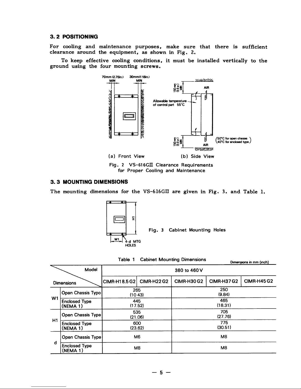
3
.2
POSITIONING
For
cooling
and
maintenance
purposes,
make
sure
that
there
is
sufficient
clearance
around
the
equipment,
as
shown
in
Fig.2
.
To
keep
effective
cooling
conditions,
it
must
be
installed
vertically to
the
ground
using
the
four
mounting
screws
.
70mm
(2
.761n
.)
30mm(1181n
.)
IN
MIN
w1
4-d
MTG
HOLES
(a)
Front
View
(b)
Side
View
Fig.2
VS-616GII
Clearance
Requirements
for
Proper
Cooling
and
Maintenance
3
.3
MOUNTING
DIMENSIONS
The
mounting
dimensions
for
the
VS-b16GII
are
given
in
Fig.3,
and
Table1.
i
Fig.3
Cabinet
Mounting
Holes
Table
1Cabinet
Mounting
Dimensions
WC
for
open
chasm
(40'C
for
enclosed type
Dimensionsinmm
(inch)
Model
380to460
V
Dimensions
CIMR-H18.5G2
CIMR-H22
G2
CIMR-H30
G2
CIMR-H37
G2
CIMR-H45
G2
Open
Chassis
Typo
265
(1043)
250
(9 .84)
W
1
Enclosed
Type
445
465
(NEMA
1)
(17
.52)
(18
.31)
Open
Chassis
Type
535
(21
.06)
705
(27
.76)
H1
Enclosed
Type
600
775
(NEMA
1)
(23
.62)
(30
.51)
Open
Chassis
Type
M6
M8
d
Enclosed
Type
M8
M8
(NEMA
1)
AIR
4
Allowable
temperature
_
of control
part
55'C
-
i
41E
AIR
Page 6
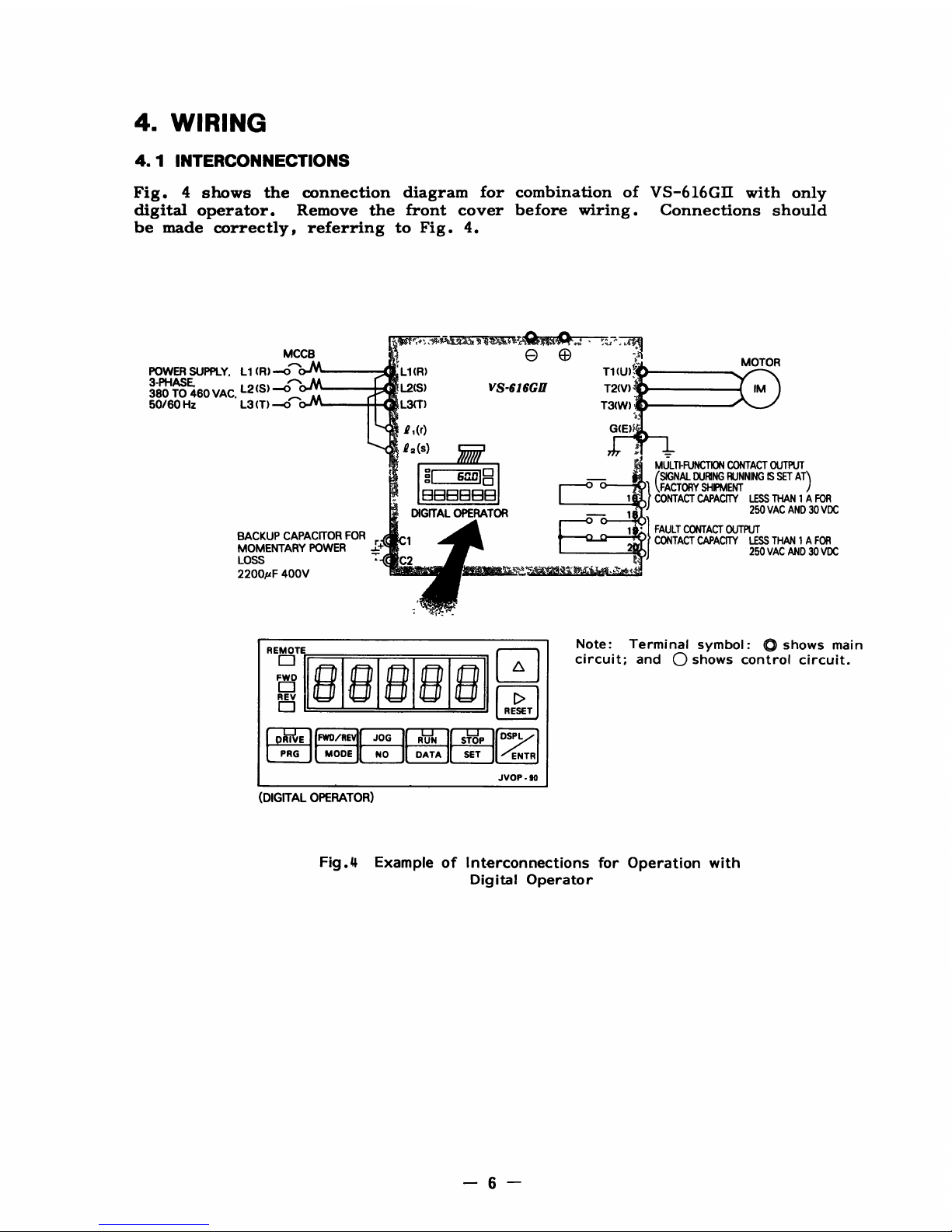
4.WIRING
4
.1
INTERCONNECTIONS
Fig
.4shows
the
connection
diagram
for
combination
of
VS-616GII
with
only
digital
operator
.
Remove
the
front
cover
before wiring
.
Connections
should
be
made
correctly,
referring
to
Fig.4
.
MCCB
POWER
SUPPLY.L1(R)
-o
L1(R)
3-PHASE'
L2(S)
L2(S)
V$-616GH
T2(V)
s
380TO460
VAC
.
-
50/80
Hz
L3
(T)
L3(T)
T3(W)
p,(r)
G(E)I
a-
12(S)
r
i
MULTI-FUNCTION
CONTACTOUTPUT
e
6^-0
C3
-
(SIGNAL
DURING
RUNNINGISSET AT)
FACTORY
SHIPMENT
16BBBE39
1CONTACT
CAPACITY
LESS
THAN1A
FOR
xDIGITAL
OPERATOR
~&
r----o
(DIGITAL
OPERATOR)
'
'
MOTOR
Note
:Terminal
symbol
:
®
shows
main
circuit;and
0
shows
control
circuit
.
T1(U)'
-
Fig
.4
Example
of
Interconnections
for
Operation
with
Digital
Operator
REMOTE
0
Fw0
II/~I
11011
I%II
ilI III
c-
1
i
REV
J
RESET
FWD/R
JOG
RUN
STOP
DS~
PRG
MODE
NO
DATA
SET
ENTR
JVOP-90
Page 7
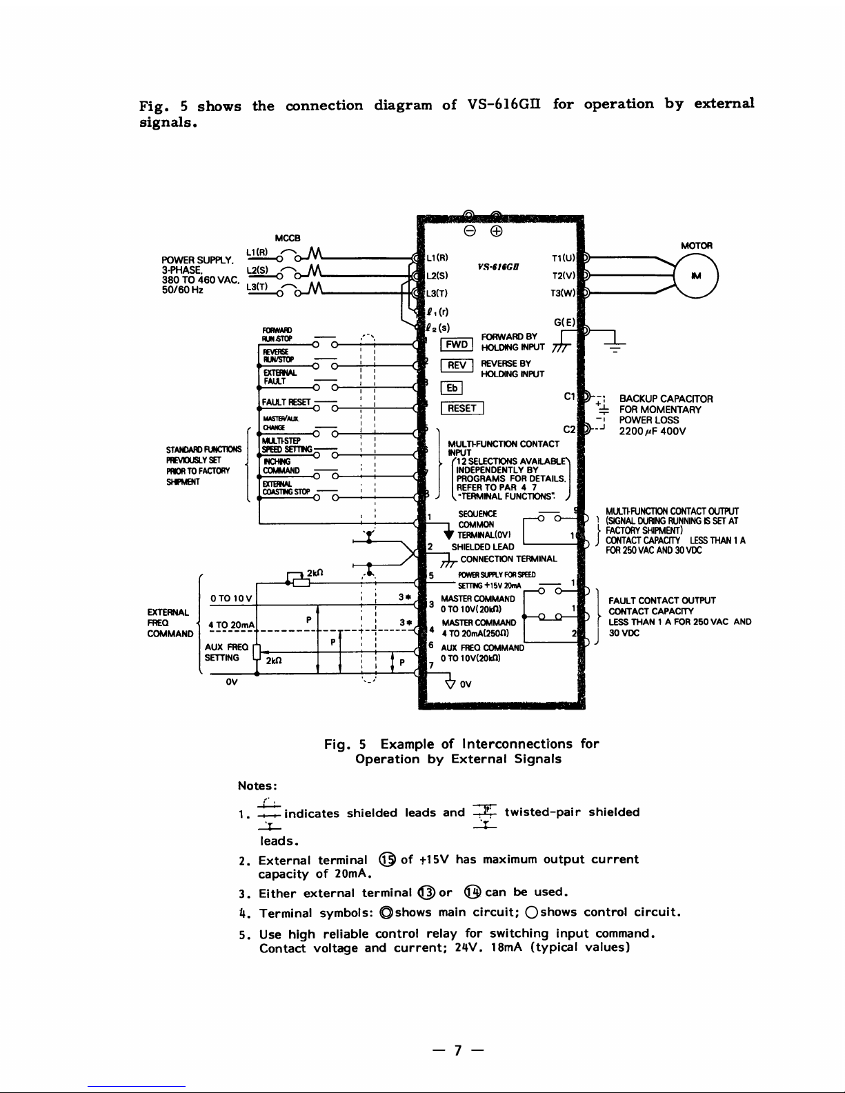
Fig.5
shows
the
connection
diagram
of
VS-616GII
for
operation
by
external
signals
.
OV
MCCB
'
Notes
:
MOTOR
b
OV
Fig.5
Example
of
Interconnections
for
Operation
by
External
Signals
1 .
-,r-indicates
shielded
leads
and
=
twisted-pair
shielded
2.External
terminal
1© oft15V
has
maximum
output
current
capacity
of
20mA
.
3.Either
external terminal03or
0
can
be
used
.
Terminal
symbols
:
®shows
main
circuit;0shows
control
circuit
.
5.Use
high
reliable
control
relay
for
switching
input
command
.
Contact
voltage
and current;24V.18mA
(typical
values)
STANDARD
PREVIOUSLY
PRIOR
TO
SHIPMW
FUNCTIONS
SET
FACTORY
MULTFSTEP
SP®
MCHNG
A6
COMMAND
jl~
I
11
.v
y
SETTNG
-
w
i
MULTI-FUNCTION
CONTACT
INPUT
12
SELECTIONS
AVAILABL
INDEPENDENTLY
BY
PROGRAMS
FOR
DETAILS
.
REFER
TOPAR
4 7
'TERMINAL
FUNCTIONS"
.
'
SEOUENCE
MULTFHJNCTIUN
GONTACT
OUTPUT
1
COMMON
(SIGNAL
DURING
RUNNINGISSET
AT
i
TERMINAL(OV)
1
FACTORY
SHIPMENT)
CONTACT
CAPACITY
LESS
THAN1A
2
SHIELDED
LEAD
FOR
250
VAC
AND
30
VDC
CONNECTION
TERMINAL
2 5 POWER
SUPPLY
FOR
SPEED
SETTNC
+15V 2OmA
1
0TO10V
3
*
3
MASTER
COMMAND
FAULT
CONTACT
OUTPUT
EXTERNAL
0TO10V(
20141)
1
CONTACT
CAPACITY
FRED
4TO20mA
3
*
MASTER
COMMAND
LESS
THAN
1
AFOR
250
VAC
AND
COMMAND
4
4TO20mA(25011)
2
30VDC
AUX
FRED
P
'
'
6
AUX
FREO
COMMAND
SETTING
2kr1
I
0
To
10V(20kf1)
P
7
POWER
SUPPLY
.
-
(R)
0
C
3-PHASE
.
L2(S)
380TO460
VAC
.
0
0-M
50/60Hz
L3(
0
0-M
L1
(R)
VS-616GH
L2(S)
L3(T)
T1(U)
T2(V)
T3(W)
IM
FORIAMAD
X2(S)
G(E)
RUNSTOP
,'
"
FORWARD
BY
O
I
FWD
BOLDING
INPUT
RUN
/STOP
O
'
'm
REV
REVERSE
BY
EXTEINAL
FAULT
Eb
FAULT
RESET
C1
-'
BACKUP
CAPACITOR
O
RESET
+
T
FOR
MOMENTARY
MKST6VNAL
POWER
LOSS
CKVQE
'
C2
' _j
2200pF
400V
Page 8

4.2MOLDED-CASE
CIRCUIT
BREAKER
(MCCB)
AND
POWER
SUPPLY
MAGNETIC
CONTACTOR
(MC)
Be
sure
to
connect
MCCBs
between
_power
supply
and
VS-616GIE
input
termi-
nals
®
T~).
Recommended
MCCBs
are
listed
in
Table2.
When
a
ground
fault
interrupter
is
used
to
prevent
malfunction,
setting
current
should
be
200mA
or
over
and
operating
time,
0.1sec
or
over
.
*Comply
with
NEMA
AB1
.
4
.3
SURGE
ABSORBER
Table
2Molded-Case
Circuit
Breakers
and
Magnetic
Contactors
For
the
surge
absorbers
to
be
connected
to
the
coils
of
relays,
magnetic
contactors,
magnetic
valves,
or
magnetic
relays,
select
types
from
the
ones
*Made
by
MARCON
Electronics
.
IMPORTANT
Lead
size
should
be
determined
considering
voltage
drop
of
leads.Refer
to
APPENDIX
10
"WIRE
SIZE"
.
ModelCIMR-
H18.5G2
H22G2
H30G2 H37G2
H45G2
VS-616GI
Capacity
kVA
34
41
54 68
82
Rated Output
Current
A
45 54
72 90
108
Mitsubishi
Molded-Case
Circuit
Breaker
Model
and
Rated
Current*
*
NF100
1
OOA
NF100
100A
NF100
100A
NF225
150A
NF225
150A
Yaskawa
Magnetic
Contactors
Model
HI-50E HI-50E HI-80E
HI-100E HI-100E
listed in
Table3.
Table 3 Surge Absorbers
Cods
of
Magnetic
Contactor
Surge
Absorber*
and
Control
Relay
Model
Specifications
CodeNo.
Large-size
Magnetic
DCR250A22E
I
250
VAC
0.5pF+
200
El
C002417
Contactors
Control
Relay
LY-2,-3(OMRON)
DC132-
I
250
VAC
C002482
HH-22.-23
(Fuji)
10A25C
0
.1pF
+
100(l
MM-2.-4
(OMRON)
Page 9
4
.4
WIRINGINSTRUCTIONS
4.4.1Control
Circuit
The
external
interconnection wiring
must
be
performed
with
following
proce-
dures
.
After
completing
VS-616GII
interconnections,
be
sure
to
check
that
con-
nections
are
correct.Never
use
control
circuit
buzzer
check
.
(1)
Separation
of
control
circuit
leads
and
main
circuit
leads
Signal leads
Ol
through
20
must be
separatedfrom main
circuit
leads
c
tT
IN
®),
Q
c0),
~
c0),
~
~+,
©
cQo,
©
c0),
©
(
Q
)
0
((D),
©2
J(D)
,
©©
,
and
another
power
cables
to
prevent
erroneous
operation
caused
by
noise
interference
.
(2)
Control
circuit
leads
9
00
®
a
(contact
output)
must
be
separated
from leads
1
to
8
and
to
©
.
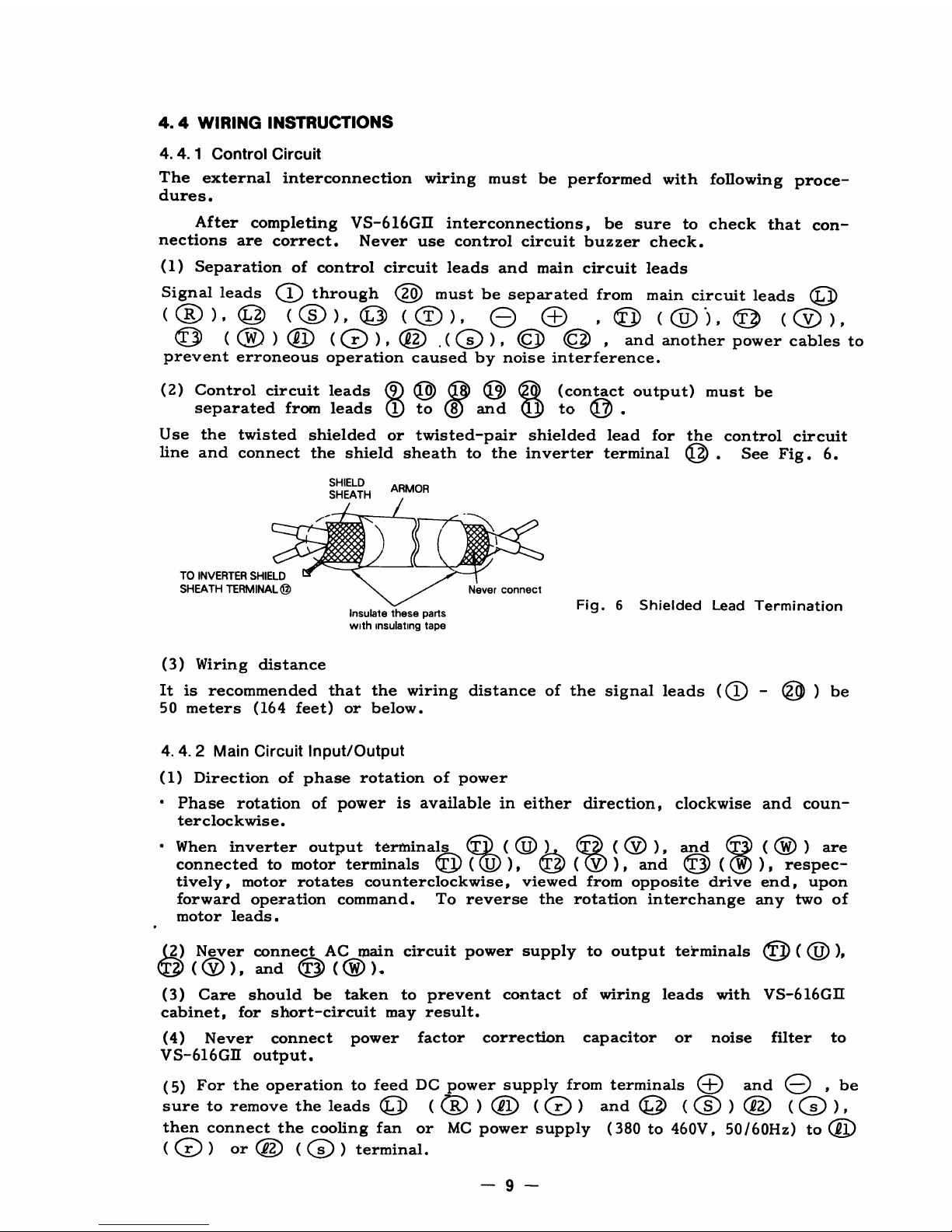
Use
the
twisted shielded
or
twisted-pair
shielded
lead
for
the
control
circuit
line
and
connect
the
shield
sheath
to
the
inverter
terminal
©
.
See
Fig.6
.
(3)
Wiring
distance
It
is
recommended
that
the
wiring
distance
of
the
signal
leads
(~
-
®)
be
50
meters
(164
feet)
or
below
.
4.4.2 Main
Circuit
Input/Output
(1)
Direction
of
phase
rotation
of
power
"
Phase
rotation
of
power
is
available
in either direction,
clockwise
and
coun-
terclockwise
.
"
When
inverter
output
terminals
(
QU
)
(
~
V),
and
(QW
)
are
connected
to
motor
terminals©(U
)
,
(V),and
(
),respec-
tively,
motor
rotates
counterclockwise,
viewed
from
opposite
drive
end,
upon
forward
operation
command
.
To
reverse
the
rotation
interchange
any
two
of
motor
leads
.
(3)
Care
should
be
taken
to
prevent
contact
of
wiring
leads
with
VS-616GII
cabinet,
for
short-circuit
may
result
.
(4)
Never
connect
power
factor
correction
capacitor
or
noise
filter
to
VS-616GH
output
.
(5)
For
the
operationtofeed
DC
power
supply
from
terminals
0
and
0
,
be
sure
to
remove
the
leads
©
(~R)Ql(
(D)
and
©
(S)Q2
(
(s) ,
then
connect
the
cooling
fan
or
MC
power
supply
(380
to
460V, 50/60Hz)
to
or
Q2(
Os
)
terminal
.
2)Never
connect
AC
main
circuit
power
supply
to
output
terminals
8
©(O
),
(O),
and
Q
(O)
.
Insulate
these
parts
with
insulating
tape
Fig.6
Shielded
Lead
Termination
Page 10
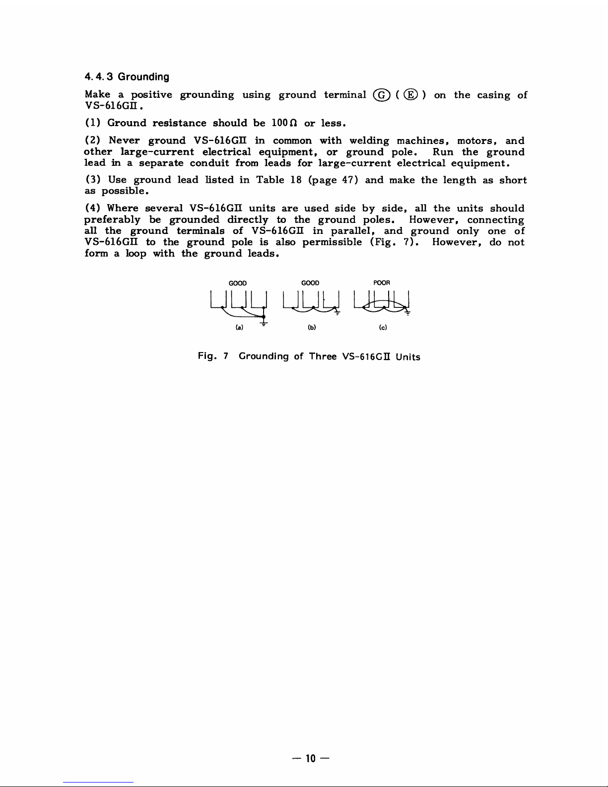
4
.4
.3
Grounding
Make
a
positive
grounding
using
ground
terminal
O
()
on
the
casing
of
V
S-616GII
.
(1)
Ground
resistance
should
be
10013
or
less
.
(2)
Never
ground
VS-616GII
in
common
with
welding
machines,
motors,
and
other
large-current
electrical
equipment,
or
ground
pole
.
Run
the
ground
lead
in
a separate
conduit
from
leads
for
large-current
electrical
equipment
.
(3)
Use ground
lead
listedinTable
18
(page
47)
and
make
the length
as
short
as
possible
.
(4)
Where
several
VS-616GII
units are
used
side
by
side,
all
the
units
should
preferably
be
grounded
directly
to
the
ground
poles.However,
connecting
all
the
ground
terminals
of
VS-616GII
in
parallel,
and
ground
only
one
of
V
S-616GII
to
the
ground
pole
is
also
permissible
(Fig
.
7)
.
However,
do
not
formaloop with
the
ground
leads
.
4
1
(a)
GOOD GOOD
POOR
Fig.7
Grounding
of
Three
VS-616GII
Units
Page 11
5.TEST
RUN
5
.1
CHECKS
BEFORE
TEST
RUN
After
mounting
and
connection
are
completed,
check
for
:
"
Correct
connections
"
Short-circuit
conditions
"
Loose
screw
terminals
(Check
especially
for
loose
wire
clippings
.)
"
Proper
load
condition
"
Proper
power
voltage
selection
Select
the
proper
position
by
AC
main
circuit
power
voltage value
as
shown
in
right
figure,
and
set
the
connector
toit.
The
voltage
is
preset
to the
posi-
tion of
460V
prior
to
factory
shipment
.
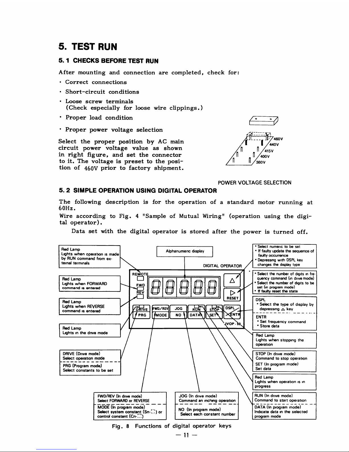
5
.2
SIMPLE
OPERATION
USING
DIGITAL
OPERATOR
The
following
description
is
for the
operation
of a
standard
motor
running
at
60Hz
.
Wire
according
to
Fig.4
"Sample
of
Mutual
Wiring" (operation
using
the
digi-
tal
operator)
.
Data
set
with
the
digital
operator
is
stored
after
the
power
is
turned
off
.
Red
Lamp
Lights
when
operationismade
by
RUN
command
from
ex-
ternal
terminals
Red
Lamp
Lights
when
FORWARD
command
is
entered
Red
Lamp
Lights
when
REVERSE
commandisentered
Red
Lamp
Lightsinthe
drive
mode
DRIVE
(Drive
mode)
Select
operation
mode
PRG
(Program
mode)
Select
constantstobe
set
k
J
FWD/REV
(In
drive
mode)
Select
FORWARDorREVERSE
MODE
(In
program
mode)
Select
system
constant
(Sri-
:_ :)
or
control
constant
(Cn-'_'
)
Alphanumenc
display
POWER
VOLTAGE
SELECTION
JOG
(In
drive
mode)
Commandaninching
operation
NO
(In
program
mode)
Select
each
constant
number
DIGITAL
OPERATOR
Fig.8 Functions
of
digital
operator
keys
/--
----
-7
l
V
4MV
440V
415V
400V
380V
'
Select
numerictobe
set
"Iffaulty
update
the
sequence
of
faulty
occurrence
'
Depressing
with
DSPL
key
changes
the
display
type
"
Select
the
numberofdigitsmfre-
quency
command
(in
drive
mode)
"
Select the
numberofdigitstobe
set(mprogram
mode)
' If
faulty
reset the state
DSPL
"
Select
the
typeofdisplay
by
depressing
p
key--
-
ENTR
'
Set
frequency
command
"
Store
data
Red
Lamp
Lights
when
stopping
the
operation
STOP
(In
drive
mode)
Commandtostop
operation
SET
(In
program
mode)
Set
data
Red
Lamp
Lights
when
operation
is in
progress
RUN
(In
drive
mode)
Command
to
start
operation
DATA
(In
program
mode)
Indicate
datainthe
selected
program
mode
w
REMOTE
0
FWD
Q
/
REV
RESET
D
F
G
E
WD/REV
JOG
RU
1
S
P
3
~
DSPL
~NT
VOP-
0
Page 12

5.2.1Set and
Operate
Frequency
Command
DRIVE
Set
frequency
command
in
drive
mode
(
PRc
Setting
DsP~
"
(1)
Depress
1n
while
depressing
then
the
frequency
command
appears
.
When
thisisrepeated,
the
display
changes
as
follows.See
(3) for
details
.
F~OUENCYC
OMMAND
OUTPUTFREQUENCY
}---~
OUTPUT
CURRENT
F--~
CONTENTOFBAST
FALURE
uuu.
u
FREQUENCY
COMMAND
IN
THE
LASTTIME
,
(2)
Using
RESET
flash
can
be
moved
to
the
digittobe
set,
and
the
numeric
set
with
[7o
key
.
(3)
Depress
DSP
NTR
to
store
the
frequency
command
value
.
(Stored
data
is
maintained
when
the
power
is
off
.)
DSP~L
(4)
Depress
17o
while
depressing
~NTR
to
select
the
output
frequency
to
be
indicated
.
Operation
FWD/REV
(5)
Depress
MODE
to
select
the
motor
rotating direction
.
RUN
(6)
Depress
DATA
to
give
run
command.The
motor
accelerates
acoording
to
the
specified
acceleration
time
(10
s)
and
holds
the
speed
at
the
specified
frequency
.
Stop
operation
STOP
(7)
Depress
SET
to
stop
the
motor.The
motor
decelerates
according
to
the
specified
deceleration
time
(10s).
Page 13

5.2.2
Monitor
Function'of
Digital
Operator
(a)
Output
freuency
display
The
output
frequencyappears
in
units
of0.1
Hz
.
7l
1~
1-11-
1
_I
0
1.1,1
.1
(-)
appears
for
reverse
rotation
(b)
Frequency
command
display
The
following
display
appears
in
units
of
0
.1Hz,
depending
on
the
operation
performed
with
the
frequency
command
either
from
the
external
terminal
or
digital
operator
.
(1)
Operation
by frequency
command
from
the
external
terminal
The
frequency
command
specified
from
the
external
terminal
appears
.
1
C
_I
1_I1_I
,1_I
Indicates
frequency
commandisappearing
(2)
Operation
by
frequency
command
from
the
digital
operator
.
The
frequency
command
specified
from
the
digital
operator
appears
.
The
digit
which
is
flashing
can
be
changed
.
A
frequency
command
can
also
be
set
.
1=
=1
1=
1~1
r1
1
IT
---
Flashing
L
Indicates
frequency
commandisappearing
(c)
Output
current
display
The
inverter
output
current
appears
in
units
of 0.1A
.
:I
1
0
1,
1_I
1
1
Indicates
currentisflowing
Page 14

5
.3
ADJUSTMENT
AND
SETTING
The
VS-616GIIhas
the
following
two
constants
to
select the
function
and
change
the
characteristics
.
Before
starting
operation,
set
these
constants
to
meet
the
operation
condition
.
"
System
constants
(Sn-O1
to
Sn-12)
:
Mainly
used
to
select
V/f
and
the
function
of
external
terminals
(Table
4)
.
"
Control
constants
(Cn-O1
to
Cn-30)
:
Mainly
used
to
change
characteristics
(Table
5)
.
Table
4
System
Constants
(S
n
Swill
.
Name
Function
Setting
Value
at
Factca
"
ent
SI
WA
selection
Sets
printed
circuit
board
constants
commonly
Used
for
multiple
inverters
Already
set
pare
pan
needs
01
S
ew
setting
16
V/f
patterns
are
available
for
use so
that
the
operation
suitedtothe
motor
4cxty
1
02
V/f
pattern
type load
characteristics.and
operation
condition
canbeperformed
selection
15
types
V/f
patternisScllectahln
try
snitinq0toE(See
lirule
29)
Z
1
type
V/f
pativrii
caii
tic
:
chancled by
sottirul
F
60Hr
03
-
-
0000
0
1
0011
1st
ControlledbyFregviwy
coniniarut ControlledbyFrequencycommaiicf
Operation
from
the
external
terminal
from the
digital
operator
04
signal
2nd
ControlledbyRun
corriniand
front
CctFOlled
by RIIn
Cnnlriland
from hK7i1
QiQq
selection
the
external
terminal
the
digital
operator
3rd
2nd
Main
speed
frequency
command
Main
speed
frequency
command
drq-1
r1Q1
3rd
0
.10V/0-100%
4-20mA/0100%
0
10V/100-096
4-20niA/100
0%
Reverse
allowed
/Controlledbydigital
4th
No
reverse
allowed
operator
1st
Operation stopsata
momentary
Operation
continuesata
power
failure
momentary
power
failure
Protection
2nd
Operation
stalls
during Operation
will
not
stall
chirinq
05
deceleration
deceleration
characteristics
3
rd
The
electronic
thermal
motor
The
electronic
thermal
motor
not
0000
selection
protected protected
4th
The
electronic
thermal
protector
The
electronic
thermal
protector
(reduced
torque)
(constant
torque)
1st
Overtoique not
detected
Oveitorque
detected
2nd
Overtorque
detected
during
speed
Overtorque
always
detected
06
Overlorque
synchronization
detection
3rdOperation
continues
Coasting
stop
0000
4th
I
1st
Used
when
the
pulse
monitor
(model
JOGB-C01)isinstalled
07
Optional
2nd
function
0000
selection
3rd
Used
when
the
interface
(model
JOGB-CO4)isinstalled
input
4th
08
xternalterminal05Select
terminal5functioninaccordance
with
table15(Page
351
0
09
I
terminalf3Select
terminal6functionnaccordance
with
table15(Page
35)
3
10
I
telminal7Select
terminal
7
function
in
accordance
with
table15(Page
35)
5
11
External
terminal
1.0Select
terminal8functioninaccordance
with
table15(Page
35)
6
12G_.~:-"
s~nrra
Select
contact output
function
in
accordance
with
table
17
(Page 40)
0
Termmai
Select
terminal(7functionofthe
output
interfaceinaccordance
with
table
0
13
Output
C~
17
(Page
401
interlace
model
terminal
Select
terminal(Dfunctionofthe
output
interfaceinaccordance
with
table
0
14
(
j0Ga
)
20
17
(Page
40)
terminal
Select
terminal
(1)
functionofthe
output
interfaceinaccordance
with
table
0
15
Open
ootleotor
p
O
17
(Page 40)
--
output
temanai
Select
terminal@functionofthe
output
interfaceinaccordance
with
table
0
16
O
17
(Page
40)
Page 15

Table
5
Control
Constants
(`nr
Control
ConstantNo.
Name
Unit
Setting
Range
Setting
Value
Prior
to
Factory
Shipment
rl
-01
Max
Frequency
(F
MAX)
01Hz
500
-
4000Hz
60Hz
02
Max
Voltage
(V
MAX)
0
1
V
00-4600V
400
V
03
Max
Voltage
Freq
(F
A)
01Hz
00-4000Hz
60
Hz
04
V/f
Constant
(F B)
01Hz
00
-
4000Hz 3
Hz
05
V/f
Constant(VC)
01V
00-
4600V
26V
06
Min
Output
Freq
(F
MIN)
01Hz 00-
4000Hz
1
5
Hz
07
Min
Output
Freq
Voltage
(V
MIN)
01V
00-
460
0V
14
V
08
Accel
Time
0
1
s
0
1
-18000S
100s
09
Decel
Time
01s
01-18000S
100s
10
DC
Injection
Braking
Voltage
01V
0
0-
2000
V
15V
1 1
DC
Injection
Braking
Timeatstop
0
1
s
00-1000S
05s
12
DC
Injection
Braking
Time
at start
01s
00-255s
00s
13
Freq
Command
Gain
001
001
-255
100
14
Freq
Command
Bias
01%
00-255%
00
1
5
Freq
Command
Upper
Limit
1
%
0-110%
100
16
Freq
Command
Lower
Limit
1
%
0-110%
0
1
7
Setting
Prohibited
Freq
1
01Hz
00
-
40001-1z
00
Hz
18
Setting
Prohibited
Freq
2
01Hz 00-
4000Hz
0
0 Hz
19
Setting
Prohibited
Freq
3
01Hz 00-
4000Hz
0
0 Hz
20
Motor
Rated
Current
01A
01-
3600A
See
Table12.
21
Carrier
Freq
Lower
1
Hz
380-2500Hz
380
Hz
22
Torque
Compensation
Gain
0
1
00-99
1
0
23
Over Torque
Detecting
Level
1
%
30-200%
160%
24
Freq
Monitor
Gain
001 001
-200
100
25
Current
Monitor
Gain
001
001
-200
100
26
Inching
Freq
01Hz
00-4000Hz
60Hz
27
Freq.Command
1
for
Multi-step
Run
01Hz
00-
40001-1z
1
00
Hz
28
Freq
Command
2
for
Multi-step
Run
01Hz
00-
4000Hz
1
0
0 Hz
29
Accel/Decel
Time
01s
01-18000S
100s
30
Save
Energy
Gain
1
%
0-120%
80%
31
Slip
Compensation
Gain
0
1
00-99
00
32
Speed
Display
(Freq,
RPM, Speed%.
etc)
1
0-39999
0
33
Optional
Speed
Agreed
Frequency
01Hz
00-
4000
Hz
00
Hz
Page 16
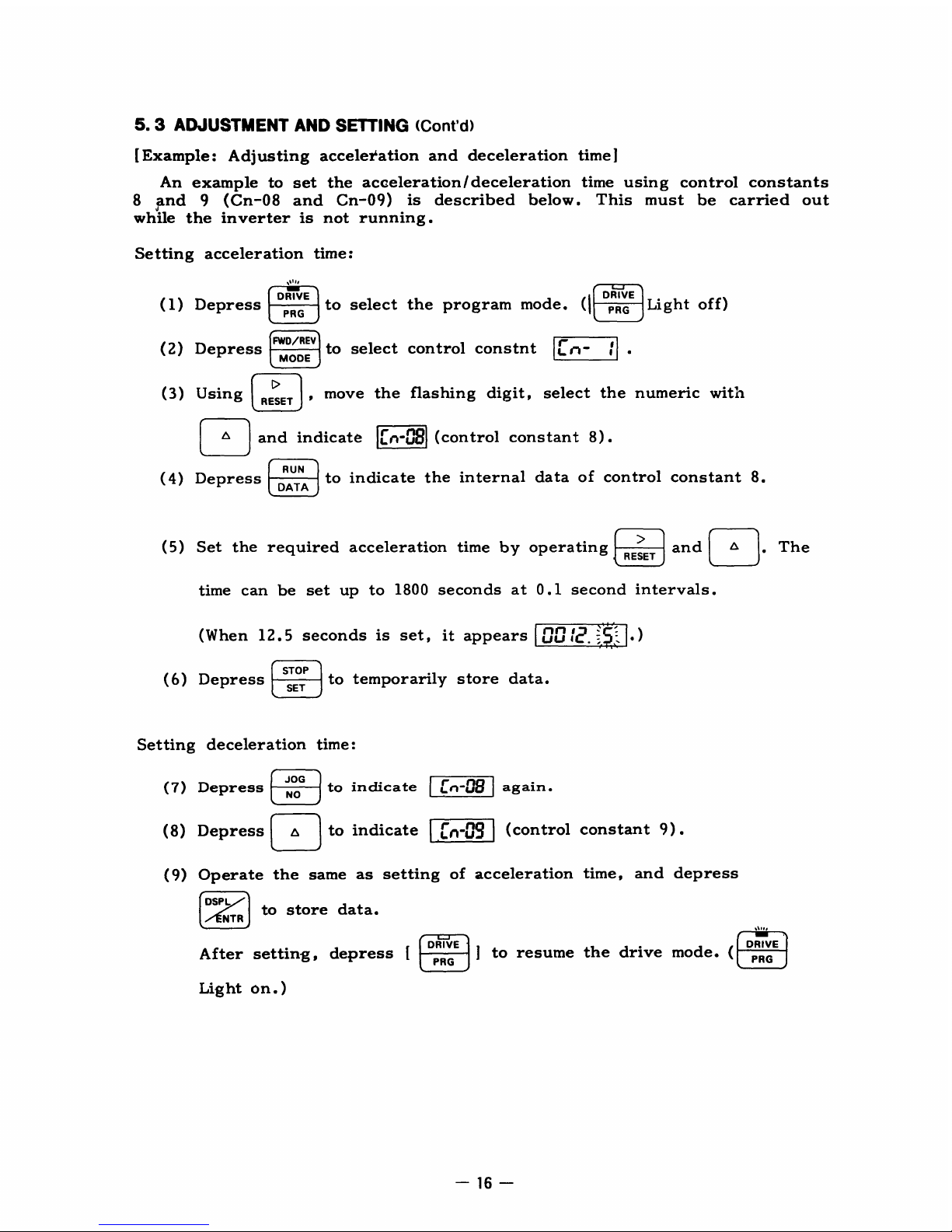
5
.3
ADJUSTMENT
AND
SETTING
(Cont'd)
[Example:Adjusting
acceleration
and
deceleration
time]
An
example
to
set
the
acceleration/
deceleration
time
using
control
constants
8
and
9
(Cn-08
and
Cn-09)
is
described
below.This
must be
carried
out
while
the inverter
is
not
running
.
Setting
acceleration
time
:
(1)
Depress
DRIVE
PRG
DRIVE
to select
the
program
mode
.
(I
PRG
Light
off)
(2)
Depress
FWD/REV
MODE
to
select
control
constnt
n-
;
(3)
Usin
g
I
RESET
I
move
the
flashing
digit,
select
the
numeric
with
with
and
indicate
ff
n
-
u
^
$
(control
constant
8)
.
(4)
Depress
DATA
to
indicate
the
internal
data
of
control
constant8.
(5)
Set
the
required
acceleration
time
by
operating
and
L-AI
.
The
RESET
time
can
be
set
up
to
1800
seconds
at0.1
second
intervals
.
(When
12.5seconds
is
set,
it
appears
UU;
.
)
STOP
(6)
Depress
SET
to
temporarily
store
data
.
Setting
deceleration time
(7)
Depress
JOG
ND
to
indicate
FL
F
n
-
u^$
again
.
(8)
Depress
1o
to
indicate
~n-n
(control
constant
9)
.
(9)
Operate
the
same
as
setting
of
acceleration
time,
and
depress
DSPL
to
store
data
.
NTR
DRIVE
After
setting,
depress
[
PRG
]
to
resume
the
drive
mode
.
Lighton. )
a1"
-77
DRIVE
,
PRG
Page 17
6.OPERATION
AT
LOAD
After
the
no-load
operation,
turn
off
the
AC
main
circuit
power,
and
connect
the
driven
machine
to
the
motor
.
Make
sure
that
the
driven
machine
is
in
running
condition,
and
that
proper
safety precaution
are
followed,
then
run
the
motor
under
load
in
exactly
the
same
way
as
the
test
run
.
For
preset
starting
(one-touch
operation
after setting
the
frequency)
Per-
form the
following
beforehand
:
(1)
Set
the
frequency
and
depress
onTn
to
accelerate
the
motor
in
the deter-
mined
time,
as
described
earlier,
and
to
maintain
the
rpm
at
the
preset
fre-
quency
.
If
the
acceleration
time
is
set
short
relative
to
the
load
and
if
the
rpm
of
the
accelerating
motor
is
not
smooth
(anti-stalling
function
during
acceleration
is
functioning)
;
or
if
trouble
is
displayed
on
the
digital
operator,
set
the
acceleration
time
longer
.
(2)
To
decelerate
the
motor
in
the preset
time
and
to
stop
it,
depress
STOP
T
T
while
the
motor
is
rotating
.
If
the
deceleration
time
is
set
short
relative to
the
load
and
if
the
rpm
of
the
decelerating
motor
is
not
smooth
(anti-stalling
function
during
deceleration
is
functioning);or
if
trouble
is
displayed
on
the
digital
operator,
set
the
deceleration
time
longer
.
(1)
Start
the
motor
after
making
sure
that
the
motor
is
stopped
.
If
the operation
is
started
during
motor
coasting,
use
the
control
constant
(Cn-12)
DC
Injection
Braking
Time
at
startintable5.
(2)
When
a
standard
motor
is
driven
with
the
inverter,
there
isalittle
increase
in
motor
temperature,
noise,
and
vibration
as
compared
to
the operation
from
the
commercial
power
sup-
ply
PRECAUTION
(3)
The
motor
cooling
effect
lowers
during
low-speed
run-
ning
.
The
torque
needs
to
be
reduced
in
accordance
with
the
frequency
.
(For the
reduction
ratio,
refer
to
the
cat-
alog
or
technical
sheet
.)
(4)
Even
with
small load,
never
use
a
motor
whose
current
exceeds
the
inverter
rating
.
(5)
When
two
or
more
motors
are
operated,
check
to
be
sure
that
the
total
motor
current
is
not
larger
than
inverter
rat-
ing
.
(6)
When
starting
and
stopping
the motor,
be
sure
to
use
the operation
signals
(FWD/REV),
not
the
magnetic
contactor
on
the
power
supply
side
.
Page 18
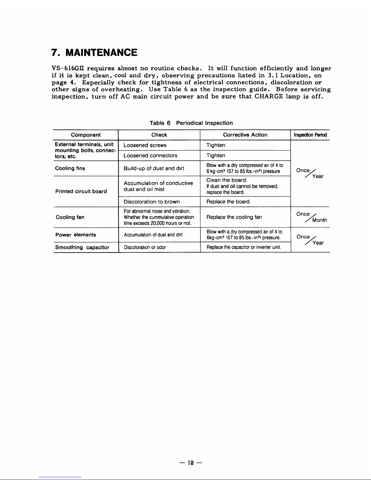
7.MAINTENANCE
VS-616GII
requires
almost
no
routine
checks
.It
will'
function
efficiently
and
longer
if
itiskept
clean,
cool
and
dry,
observing
precautions
listedin3.1Location,
on
page4.
Especially
check
for tightness of
electrical
connections,
discoloration
or
other
signs
of
overheating.Use
Table6as
the
inspection
guide.Before
servicing
inspection,
turn
off
AC
main
circuit
power
and
be
sure
that
CHARGE
lamp
is
off
.
Table
6
Periodical
Inspection
Component
Check
Corrective
Action
Inspection
Period
External
terminals,
unit
Loosened
screws
Tighten
mounting
bolts,
connec-
tors,
etc
.
Loosened
connectors
Tighten
Cooling
fins
Build-up
of
dust
and
dirt
Blow
withadry
compressed
airof4
to
Once
6kgcm
(57to85
lbs
.-in)
pressure
Year
Accumulation
of
conductive
Clean
the
board
.
dust
and
oil
mist
If
dust
and
oil
cannotberemoved,
Printed
circuit
board
replace
the
board
.
Discolorationtobrown
Replace
the
board
.
For
abnormal
noise
and
vibration
.
OnceOnce
Cooling
fan Whether
the
cummulative
operation
Replace
the cooling fan
time
exceeds
20,000
hoursornot
.
Power
elements
Accumulationofdust
and
dirt
Blow
with
a dry
compressed
airof4
to
Once
6kgcm2(57to85
Ibs..in
2)pressure
.
ear
Smoothing
capacitor
Discolorationorodor
Replace
the capacitororinverter
unit
.
Page 19
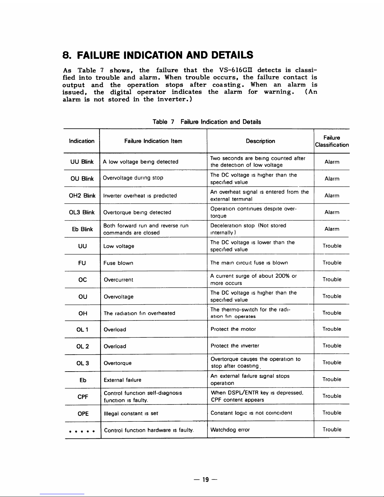
8.FAILURE
INDICATION
AND
DETAILS
As
Table
7
shows,
the
failure
that
the
VS-616GII
detects
is
classi-
fied
into
trouble
and
alarm.When
trouble occurs,
the
failure
contact
is
output
and
the
operation
stops
after
coasting
.
When
an
alarm
is
issued, the
digital
operator
indicates
the
alarm
for
warning
.
(An
alarm
is
not stored
in
the inverter
.)
Table
7Failure
Indication
and
Details
Indication
Failure
Indication
Item
Description
Failure
Classification
UU
Blink
A
low
voltage
being
detected
Two
seconds
are
being
counted
after
Alarm
the
detectionoflow
voltage
OU
Blink
Overvoltage
during
stop
TheDCvoltageishigher than
the
Alarm
specified
value
An
overheat
signalisentered
from
the
OH2
Blink
Inverter
overheatispredicted
Alarm
external
terminal
OL3
Blink
Overtorque being
detected
Operation
continues
despite
over-
Alarm
torque
Eb
Blink
Both
forward
run
and
reverse
run
Deceleration stop (Not
stored
Alarm
commands
are
closed
internally
)
TheDCvoltageislower
than
the
UU
Low
voltage
specified
value
Trouble
FU
Fuse
blown
The
main
circuit
fuseisblown
Trouble
OC
Overcurrent
A
current
surgeofabout 200°
or
Trouble
more
occurs
TheDCvoltageishigher
than
the
OU
Overvoltage
specified
value
Trouble
The
thermo-switch
for
the
radi-
OH
The
radiation
fin
overheated
fin
Trouble
ation
operates
OL
1
Overload
Protect
the
motor
Trouble
OL
2
Overload
Protect
the
inverter
Trouble
OL
3
Overtorque
Overtorque
cau$es
the operation
to
Trouble
stop
after
coasting
.
An
external
failure
signal
stops
Eb
External
failure
Trouble
operation
CPF
Control
function
self-diagnosis
When
DSPL/ENTR
keyisdepressed
.
Trouble
functionisfaulty
.
CPF
content appears
OPE
Illegal
constantisset"
Constant
logicisnot
coincident
Trouble
. ... .
Control
function
hardwareisfaulty
.
Watchdog
error
Trouble
Page 20

8
.1
DISPLAYING
THE
SEQUENCEOF
FAILURE
OCCURRENCE
Failure
items
that
currently
occur
and
that
occurred
before
the
power
was turned
off
can
be
sequentially indicated
by
the
following
procedure
(1)
To
indicate
the
sequence
of
failure
items
that
currently
occur
When
U
is
depressed,
the
sequence
of
trouble
occurrence
appears
(up
to
four
faults),
except
for
OPE
(illegal
constant
setting)
and
control
function
hardware
fault
.
[Example
of
Indication]
PASSED
THE
RESET
First
indication
OC
~2
Depress
n
1
OC
~3
Depress
1&1
2
OV
[Example
of
Indication]
After
the
power
is
turned
on
Oc
OOCffVCE
OV
OCCURRENCEOH OCCURRENCE
2)
The
first
display
:
0
[The type
of
display
selected
before
turning
off
the
power
U1--
appears
in
step3).
-20-
®
Depress
F&-1
3
OH
©
Depress
ap
1
OC
Returns
to
02
state
.
(2)
To
indicate
the
sequence
of
failure
items
that
occurred
before
the
power
was
turned
of
f
The
VS-616GII
uses
NV-RAM
to
store
the
sequence
of
failure
items
that
occurred
before
the
power
was
turned
off
(when
low
voltage
is
detected)
.
Therefore,
when
the
power
is
turned
on
again, the
sequence
of
such
failure
items
(up
to four)
appears
on
the
digital
operator
display
.
PASSED
THE
RESET
OC
OCCURS
OH
OCCI
POWER
OFF
POWER
ON
1)
The
first
failure
item that
occurred
before
the
power
was turned
off
appears:U1
OC
. . . .
Blinks
5
seconds
3)
Depress
[g
+
DSPL/ENTR
to
display
the
sequence
of
failure
occurrence
:
U1OC
4)
Depress
9
:
U2'
OH
5)
Depress
FAI
:
U1OC
Returns
to2
)
6)
Return
to
the
display
type
selected
before
depressing
a
+
DSPL/ENTR
to
display
the
sequence
of
failure
occurrence
:
0
Note
:
Ifnofailure
item
occurred
before
the
power
was
turned
off,
Page 21

8.2
STORAGE
FUNCTION
AT
POWER
FAILURE
The
VS-616GII
uses
the
internal
NV-RAM
to
store
the
following
items
after
the
power
has
been
turned
off.Therefore,
when
the
power
is
turnedon
again, the
operation
can
begin
with
the
same
state as
when
the
power
was
turned
of
f
.
"
Display
items
in
drive
mode
"
Frequency
command
from
the
digital
operator
"
The
sequence
of
failure
items
that
occurred
before
the
power
was
turned
off
(including
the
content
of
CPF
failure)
.
Page 22

9.TROUBLESHOOTING
If
the
VS-616GII
malfunctions,
find
the
cause
and
take
the
corrective
action
by
following
the
flowcharts
given
in
this
section
.
If
the
cause cannot
still
be
located
by
the
flowcharts,
the inverter or
some
parts
are
damaged,
or
any
other
problem
occurs,
contact
Yaskawa
rep-
resentative
.
9
.1
TROUBLESHOOTING
FOR
MOTOR
SYMPTOM
(1)
Motor
will
not
run
.
For
operation
from
extenal
command
through
external
terminals
(DigitalorAnalog
operator
not
used
.)
Legend
of
Chart
Symbols
C
Motor
wdl
not
run
CHARGE
lamp
on?
YES
\Qa
and
6i
.)/
YES
Continuedto"-Aon
page
23
NO
The
beginning
of
the chart
Rated
voltage
across
terminals
(R)
.2(S)
.1-+(TP
NO
YES
Decision
"Yes
.''or
'No
FAULT
lampofdigital
YES
Make
checksinpare
93
operator
on
Process
Action)srequired
or description
of
NO
situation
RUN
NO
lamp
on?
YES
STOP
command
sW
on?
(Appox24VDC
YES
Release
STOP
command
acme
ft-
nand,.
n
and~f)
NO
RUN
command
NO
hVW(0VDC
across
terms
"andior
"and
2 )
Input
RUN
command
YES
i
Approx
15
VDC
across
terms
NO
inverterisfaulty
0
and
a?,
YES
/
Fraqu.roy
-1
1
ralnsna
irg-9
(VOSpa
oulpul
NO
input
frequency
reference
axon
Urms
.0andQ.
Page 23

(2)
Motor
stalls
during
acceleration
Contact
YASKAWA
to
checkdspecial
molotisused
Acceleration
YES
time
too
short?
NO
Load
torque
too
high?
NO
NO
Load
inertia
large?
YES
V/f
set
optimum
V/f
NO
selection
appro-
priate?
YES
YES
Motor
terminal voltage
dropped'
NO
-23-
O
Continued
from
Oki
on page22
Voltage
present
NO
4
across
output
terminals
Inverterisfaulty
n
a
.)©(Q))
.Q(fo1+)~
YES
YES
--Voltage
present
NO
across
motor
terminals
Check
wiring
between
,~
()
@(rV,
)
~(~ip
),
inverter
and
motor
-
VoRT
betw©ee
1
n
NOP4.(,0,
N
1
Inverterisfaulty
j
©(4M)
balanced?
(phase
voltage
differential
YES
within2%)
"
Cut
off
power
supply
and
increase
inverter
V/f
Load
torque
too large?
NO
Motorisfaulty
Extend
acceleration
time
V/f
selection
appro-
priate
YES
YES
YES
NO
"
Reduce
bad
torque
(disconnect
load)
"
Replace
with
inverter
of
larger
capacity
"
Usealarger
lead for
connecting
motor
and
inverter
Set
optimum
V/f
"
Shorten
wiring
distance
between
motor
and
inverter
Page 24

APPENDIX
1
STANDARD
SPECIFICATIONS
Table
8Standard
Specifications
Inverter
Model
CIMR
,- '
*
Our
standard
4-pole
motorisused
for
Max
Applicable
Motor
Output
t
For
380to480V.
ride-through
functionupto2sec
momentary
power
loss
availablebyconnecting
backup
capacitor
2200
14F
400V
between
external
terminals
ct
andC2
f
Temperature
during
shipping
Storing
in this
temperature
foralong-period
may
deteriorate
main
circuit
capacitor
cuntact.your
Yaskawa
representative
-24-
380to460
V
H18.5G2
H22G2
H30G2
H37G2
H45G2
Inverter
Capacity
KVA
34
41
54
68 82
Rated
Output
Current
A
45 54
72
90
108
Output
Over
Load
Current
forAone
minute
56
68 90
113
135
Characteristics
Max
Ap
icable
Overload
Capacity
125%
for
one
minute
22
(30)
30
(40)
37
(50)
45
(60)
55
(75)
Output
kW
(HP)*
Overload
Capacity
150%
for
one
minute
185
(25)
22
(30
)
30
(40)
37
(50)
45
(60)
Max
Output
Voltage
3-Phase.380/400/415/440/460
V
(Proportional
to
input
voltage)
Rated
Output
Frequency
50, 60,72.
90,
120.180Hz(upto400
Hz
available)
Power
Rated
Input
Voltage
and
Frequency
3-Phase
380/400/415/440/460
V
50/60
Hz
Supply
Allowable
Voltage
Fluctuation
±
10%
Allowable
Frequency
Fluctuation
t5%
Control
Method
Sine
wave
PW
M
Frequency
Control
Range
01to400Hz
Frequency
Accuracy
Digital
command
001
%
(+14
10to40*C
to
104'F)
Analog
command01%
(25
77
±18
±10
:C)
F
Control
Frequency
Resolution
Digital
operator
reference01Hz.
Analog
refence
006Hz/60
Hz
Charac-
Output
Frequency
Resolution
001
Hz
teristics
Overload
Capacity
125%
for
one
minuteor150%
for
one
minute
(Load
rate
for
max
applicable
motor)
Frequency
Setting
Signal
0
to10VDC
(20
0
-
1)
4-20mA(
250
Q
Accel/Decel
Time
01
to
1800
sec
(Accel/Decel
time
setting
independently)
Braking
Torque
Approx
20
%
No.of
V/f
Patterns
(Totalof16)
4
For
general
purpose4For
high
starting
torque1For
adjustable
pattern
4
For
fans
and
pumps
3
For
machine
tools
Motor
Overload
Protection
Electric
thermal
overload
relay
Instantaneous
Overcurrent
Motor
coasts
toastopatapprox
200%
rated
current
Fuse
Blown
Protection
Motor
coaststoa
stopbyblown-fuse
Overload
Motor
coaststoa
stop
at
125%
load
for1minute
Protec-
Overvoltage
Motor
coaststoa
stopifconverter
output
voltage
exceeds
790
V
tive
Undervoltage
Motor
coasts
to a
stopifco
nverter
output
voltage
dropsto420V
or
below
Functions
Momentary
Power
Loss
Immediately
stopby15msand
above
momentary
power
loss.(Continuous
system
operation
during
power
loss
less
than
0
2
sec)
t
Fin
Overheat
Thermostat
Stall
Prevention
Stall
preventionatacceleration
/deceleration
andcon
stant
spee
d opera
tio n
Ground
Fault
Provided
by
electronic
circuit
Power
Charge
Indication
Charge
lamp
stays
ONuntil
bus
voltage
drops
below
50V
Location
Indoor
(protected
from
corrosive
gases
and
dust)
Environ-
Ambient
Temperature
+14to104*F
-10to+40*C(not
frozen)
mental
Condi-
Storage
Temperature
f
-4to140* F
-20to+60-C
tions
Humidity
90%RH
(no
condensation)
Vibration
1
G
less
than20Hz.upto02Gat20to50
Hz
Page 25

APPENDIX
2
TERMINAL
FUNCTIONS
A2-1
Terminals
of
Main
Circuit
Table
9Terminal
Functions
and
Voltages
of
Main
Circuit
A2-2
Terminals
of
Control
Circuit
Table
10
Terminal
Functions
and
SignalsofControl
Circuit
Terminals Functions
Levels
-
Model
ClMR-H18-5B
to
-1-175B
L1 (R
)
3-phase
L2
(S)
Main
circuit
input
power
supply
380/400/415/440/460
VAC
at
50/60Hz
L3
(T)
(Voltage
fluctuation
±1096)
1
(r)
Control
2(s)
circuit
input
power
supply
T1
(U)
3-phase
T2(V)
VS-616GI
output
380/400/415/440/460
VAC
T3
(W)
(corresponding
to input voltage)
+Q
O
Braking
unit
Approx600
VDC
CC
2
Backup
capacitor
for
momentary
power
loss
Approx300
VDC
G
(E)
I
Ground
terminal
-
Terminals
Functions
Levels
1
Forward
operation-stop
signal
Runatclosed,
stopatopen
2 Reverse
operation-stop
signal
Run
at
closed,
stopatopen
3
External
fault
input
Faultatclosed
4
Fault
reset
input
(external)
Fault
resetatclosed
5 Following
sequence
control
commands
availabletoselect
5-step
speed
setting
.
Master/Aux
selector,
Master/Aux
6
selectoratforward
run,
Mastet/Aux
selectoratreverse
run,
Energy
saving
operation,
Override,
External
coasting
stop
7
command,
Forward
inching
operation.Reverse
inching
operation
.
Coasting
stop
command.Speed
search
from
top
8
speed,
Speed
search
from
setting
value.Accel/decel
time
selection
Oneofthe following
signals
availabletoselect
During
running,
Contact
capacity
250
VACat1Aor
below
10
Zero
speed
Synchronized
speed,
Over-torque.Under
voltage
(NO)
30
VDCat1Aor
below
11
Sequence
control
input
common
terminal
Sequence
control
input0V
12
Connectiontoshield
sheath
of signal lead
-
13
0to-f-10V(20
kil)
14
Master speed frequency
reference
input
4_20
mA
(25
0-
0)
15
+1
5V(Corftrol
power
supply
for
frequency
setting
max20mA)
16
Aux
frequency
reference
input
0
to
+10
V/100%(20
kfl)
17
OV
18
Common
19
Fault
contact
output
(NONC)
Openatfault
Contact
capacity
250
VAC
at1Aorbelow
20
Closedatfault
30
VDC
at1Aorbelow
Page 26

(1)
Terminals
O
,
O2
(Forwardrun
command,
reverse
run
command)
Status
signals
shown
in
Table
11
.
Table
11Forward/Reverse
run
command
Note:Time
chartatforward
runisshown
in
Fig.9
.
FORWARD
RUN
COMMAND
(2)
Terminal
3O
(external
fault
input)
(3)
Terminal
®(reset
fault)
FREQUENCY
COMMAND
ACCEL
TIME(8)
OB
-MINOUTPUT
FREQUENCY(6)
DB
OUTPUT
FREQUENCY
I
v
v
DC
INJECTION
BRAKING
TIMEATSTART
(12)
0C
INJECTION
BRAKING
TIMEATSTOP
(11)
Fig
.
9
Time
chart
at
forward
run
Note-
Parenthesized
values
indicate
the
number
of
control
constant
.
(See
page
15
. )
When
an
external
fault
is
input,
the
inverter
coasts
toastops
and
the
digital
operator
indicates
Eb.Data
is
stored
in
the
inverter
untilafault
reset
is
in-
put
.
Used
to
reset
fault.This
is
effective
when
both
forward
and
reverse
comand
are
open
.
(4)
Terminals
05
,
©
,
0
,
and
®
(sequence
functional terminals)
The
function
of
terminal
~5
is
selected
by
the
value
set
to
system
constant
8
.
Similarly,
the
function
of
terminal
6
is
selected
by
the
value
set
to
system
constant9;
the
function
of
terminal
7
by
the
value
set
to
system
constant
10
;
the
function
of
terminal
®by
the
value
set
to
sytem
constant
11.(See
Par,
A4
.7
Terminal
Function)
.
DECEL
TIME(9)
Forward
run
.command
Reverse
run
command
Description
Open
Open
Deceleration
and
stop
(Stop
indication
is
delayed
100
ms
)
Closed
Open
Forward
run
Open
Closed
Reverse
run
Closed Closed
The
digital
operator
flashesEband
when
both
are closed
for
500msor
more.It
decelerates
and
stops
the
motor
(not
stored
internally)
Page 27

(5)
Terminals
90-
(10
(multifunctional
contactoutput)
The
output
items
from
terrminalsl9-
©0
are
selected
by
constant
12.(See
Par
A4-8
Contact
Output
Selection
Function)
Contact
capacity
:
250
VAC,
1Aor
less
30
VDC,
1Aor
less
(6)
Terminals
and
14
(main
speedfrequency
command)
Used
to
connect
the
master
speed
frequency
command
.
When
the
master
speed
frequency
command
is
set
with a~
voltage,
connect
terminal
13
;
when
set
with
a
current,
connect
terminal
(7)
Terminal
16
(auxiliary
frequency
command)
Used
to
connect
auxiliary
frequency
command
.
The
function
may
differ
depend-
ing
on
the
values
set
to
system
constants
8
and9.
(8)
Terminals
18-19 - 20
(fault
contact
output)
When
a
fault
occurs,
terminals
®
-
20-close
and
terminals
19 -
©0
open
.
Contact
capacity
:
250
VAC,
1Aor
less
30
VDC,
1Aor
less
Page 28

APPENDIX
3
INTERNAL
CIRCUIT'
AND
INTERCONNECTION
DIAGRAMS
A3-1
With Braking
Unit
and
Braking
Resistor
Unit
POWER
SUPPLY,
3-PHASE
-~
-
I
380/400/415/440/460
VAC
50/60
Hz
MCCB
MC
FAULT
CONTACT
687-193
-------------
--..-----------
1
1
2
*OVERLOAD
RELAY
~
The
sequence
to
break
power
TRIPCONTACT
supply
sidebrequired
at
overload
relay
trip
contact
VS-616GII
BRAKING
RESISTOR
BRAKING
UNIT
UNIT
11kW
C'+1BACKUP
CAPACITOR
B
EXTERNAL
FAULT
T
FOR
MOMENTARY
INPUT
POWER
LOSS
FAULT
CONTACT
OUTPUT
Cz
2200pF
~
400V
L1
(R)
T
1(U
L2(S)
T
2N
VS-
616
G
L3(T)
T3(W
MODEL
CIMR-11
G2
Q
,
(r)
.P
.
(s)
Page 29

SETTING
UPON
THE
DELIVERY
A3-2
With
Transistor
(Open-Collector)
For
Start/Stop
Operation
Lt
(Fi)
POWER
SUPPLY.3-PHASE
L2(S)
380/400/415/440/460
VAC
-p
50/60
Hz
L3(T)
0
FORWARD
RUN/STOP-0
O
REVERSE
RUN/STOP
-0O
EXTERNAL
FAULT
INPUT-0O
FAULT
RESET
-O
O
MASTER/AUX
FREQUENCY
REERENCE
SELECTOR
-0
O
MULTI-STEP
SPEED
SETTING
COMMAND
-0
O
INCHING
REFERENCE
-0O
EXTERNALBASE
BLOCK-6--
c
TRANSISTOR
OPERATION
On
(Current
sink
state)
at
(
closed
contact
EXTERNAL
FRED
COMMAND
Notes
:
0TO10V
K
AUX
FRED
SETTING
MCCB
IMPORTANT
Switching
betvveen
master frequency
command
at
external terrnmal®or®and aux
frequency
camiardet®
cortespondstothe master/aux
sebctoon
contact
nput
O
VS-61IGH
C
7
RESET
MULTIFUNCTION
CONTACT
INPUT
"
w
5
POWER
SUPPLY
FOR
SPffD
SETIRIG
+15V2OmA
1
'
Note
3
MASTER
FRED
COMMAND
1
FAULT
CONTACT
OUTPUT
'
3
0 TO
10V(
20141)
1
CONTACT
CAPACITY
Note
3
MASTER
FREQ
COMMAND
LESS
THAN1A
FOR
250
VAC
--rt____---
4
4 TO
20mA(250n)
_
AND30VDC
6
AUX
FRED
COMMAND
0 TO
10V(20k(I)
1AFOR
250
VAC
AND30VDC
SEQUENCE
COMMON
TERMINAL(OV)
OV
1_
6
-
.*-
indicates
shielded
leads
and
:D~E
twisted-pairshielded
iT
leads
.
2.External
terminal
©of
+15V
has
maximum
output
current
capacityof
20mA
.
3
.
Either
external
terminal
(g
or
©can
be
used
.
C,
BACKUP
CAPACITOR
+T
FOR
MOMENTARY
C
j-,
POWER
LOSS
2200pF
400V
4.Terminal
symbols:@
shows
main
circuit;Oshows
control
circuit
.
4TO20rnA
_------
MOTOR
C
C
G(E)
FORWARD
BY
FWD
HOLDING
INPUT
REV
REVERSE
BY
HOLDING
INPUT
RE
Page 30

APPENDIX
4
SYSTEM
CONSTANTS
A4-1
Inverter
Capacity
Selection
(Sn-01)
As
Table
12
shows,
the inverter capacity
has
been
set
already.To
use
a
spare
printed
circuit
board,
set the
desired
capacity
.
'
The
reference
current
for
setting
the
overtorque
detection
level
[Cn-23)
and
stall
prevention
during
operation
(On-18)
.
(See
page
51
.)
Table12.A
Model
and
Code
No.of
Control
PC
Board
Control
PC
Board
Model
Code
No
.
H18
.5G2
H22G2
H30G2
JPAC-C405
-,':'.'_'
ET000938X-S'
:
;,':;XX
H37G2
H45G2
indicates the
contents
of
function
.Use
the
PC
board
with
Inverter
Model
(CIMR-'_":;)
Table
12
Inverter
Capacity
Selection
same
model
or
code
No.asspare
parts
.
`xxindicates
the
number
of
design
change.Use
the
PC
board
with
same
number
or
more
as
spare
parts
.
Max
Applicable
Motor
Rated
Reference
Current
Sn"01
Model
Motor
Output
Inverter
Rated
Current
A
for
Constant
Data
(CIMR-':;':;)
kW(HP)
Current
A
(Factory
setting)
Setting*
A
18
H18.5G2
18
.5(25)
45
I
33
.4
38
19
H22G2
22
(30)
54 38
.5
45
1
A
H30G2
30
(40)
72
52
.3
60
113
H37G2
37
(50)
90
653
75
1
C
H45G2
45
(60)
108
78
90
Page 31

A4-2
Setting
of
V/f
Pattern
Selection
(Sri-02)
The
V/f
pattern
selector
switch
(Sri-02)
has
been
factory-set
at
the
notch
Ol
for
most
applications
.
For
specific
applications
such
as
fans
andpumps,
high-starting
torques,or
machine
tools,
select
the
optimum
V/f
pattern
for
motor
running,
according
to
the
load
characteristics
.
(See
Table
13
.)
IF
Sn-02
is
set
toOF
,
arbitrary
V/f
pattern
can
be
selected
with
control
constants
1
to
7
.
Table
13
V/f
Pattern Selection
(15
Patterns)
*See
APPENDIX5on
page42to
change
V/f
pattern
Notes1
Take
accountofthe
following
conditions
and
others
when
selecting
V/f
pattern
"
Pattern
matching
the
voltage-frequency
characteristicofthe
motor
"
Accordingtothe
maximum
motor speed
2
V/f
pattern
for
high
starting
torque shouldbeselected
for
"
Long
wiring
distance
.
"
Large
voltage
dropatstart
.
"ACreactor
connected
to
inputoroutputofthe
inverter
.
"
Useofmotor
of
the
rating
below
the
max
For
details.contact
Yaskawa
representative
.
aplli-
Specification
Sn-02
V/f
Pattern
capon
Specification
Sn-02
V/f
Pattern
400
(V)
Starting
4w!_________
Torque
Low
50Hz
o0
m
50Hz
0
Starting
8g
-
'
28
14
1
.2
Torque
~g
'
24
2
0
12525
50(Ht)
High
0125'25
50(11,1
C
a,
60Hz
4oo(v)_
_
°
Starting
400
(v)
.
_ . . ....
a
Satu-
*
©
Torque
ration
v-)
Low
a
=
60Hz
o~
50Hz
Qq
m
50Hz
Starting
366-
.-
C
Satu-
T
28
__
14
Torque
®
20
;
ration
0
15 3
50 BO (H
:)
High
015
3
60
(H,)
400-
v)-----------
40o
(v)
_
_
__
72Hz
®
90Hz
28
--
O
30
14
0
18 96 80 72
NO
F-
C_
14
0 22545
60
90111,1
Variable
40(v!___
. .
L
400'0.-
.
F-
.
Torque
(
;
0
1
© o
120Hz
-r-
50Hz
loo
,
a
Variable
7
°
a
70
-
,
0
E
Torque
0
0
32
,
(1)
a
2
0
125
25 50
0111
=
0
3 6
fio
'20
(11,1
Q
c
+'
o
m
Variable
(v)
400------------
,
N
(v)
4
~
,-
m
Torque
©
o
wv
U
,
`
180Hz
'
60Hz
Variable
100
70
.___
'
60
Torque
0
18
504
;
1
0 15
30
80
(Ht)
0
4 5
6
60
1880
(Ht)
Page 32

A4-3
Run
Signal
Selection
(Sri-04)
The
run
command
and
frequuency
command
that
are
validated
by
a
combination
of the
1st
and
2nd
digits
differ
(See
Table
13)
.
(1) 1st
digit
(frequency
command
selection)
0:Runsby
the
frequency
command
from the external
terminal
.
1:Runs
by
the
frequency
command
from
the
digital
operator
.
(2)
2nd
digit
(run
command
selection)
0:Runsby
the
run
command
from the
external
terminal
.
1:Runsby
the
run
command
from the
digital
operator
.
Note
1 :
Mutt[-step
speed
run,
master
speed/auxiliary
switching,
forward
master
speed/auxiliary
switching,
reverse
master
speed/auxiliary
switching,
override,
and
inching
run
commands
are
invalid
.
2.Valid
when
the
forward
run
command,
reverse
run
command,
and
DB
command
are
open
.
3.When
A
key and
STOP/SET
key
are
depressed
at
the
same
time,
the
motor
decelerates
and
stops
while
STOP
LED
flashes
.This
stop
command
is
stored
in
the
inverter
.
Therefore,
to
resume
operation,
open
both
the
forward
run
command
and
reverse
run
command
of
the
external
terminal
.
-32-
Table
13
Combination
of
Frequency
and
Run
Commands
effectiveX:
not
effective)
Command
System
Constant
4
00
Setting
Value(1st
and2nd
digits)
01
10
11
Forward
run
command
0
0
X
X
Reverse
run
command
0 0
X
X
External
fault
0
-
-1
0
I
0
0
Fault
reset
Note
2
Note
2
0
0
W
Command
of
terminal
(3)
0
Note
1
X
X
H
Command
of
terminal
0
Note
1
X
X
E
Command
of terminal
70
0
Note
1
X
X
m
x
Command
of terminal
0
Note
1
X
X
w
Master
freq
command
0
X
0
X
Aux
input
0
X
I
X
X
Fault
contact
output
I
0 0 0
_0
Contactofterminals
@-@
I
0 0 0 0
Freq.command
I
X
I
0
X
O
Run
key
I
X
I
X
0
Jog
key
o
Stop
key
Note
3
Note
3
0 0
FWD/REV
key
X
X
0
0
O
&/RESET
rDRIVE/PRG
key
key
Note
2
Effective
duinrg
stop
Note
2
0 0
Effective
during
stop
Effective
during
stop
Effective
during
stop
REMOTE
LED
I
ON
I
ON
I
OFF OFF
MONITOR
indication
I
0
0
0
0
Page 33

(3)
3rd
digit
(master-speed
frequency
command)
Depending
on
the
3rd-digit
value,
the
input
method
of
the
master-speed
fre-
quency
command
differs
as
shown
in
Fig
.
10
.
-----
3rd
digit=
0
0
3rd
digit=1
0
z
z
Q
Q
10016
fr----
10096
U
i
U
U
Z
W
W
W
096
(4)
4th
digit
(reverse
prohibit)
A4-4
Protective
Characteristics
Selection
(Sn-05)
U
Z
4MA
20mA
096
OV
10V
INPUT
CURRENT(TERMINAL®)
INPUT
VOLTAGE(TERMINALq)
Fig.10
Input
method
of
Master
Frequency
Command
4th
digit=1:Disregards
the
reverse
run
command
from the external
terminal
or
digital
operator
.
(1)
1st
digit
(operation
continues
at
momentary
power
failure)
1st
digit
= 0
:
A
momentarypower
failure,
when
detected,
is
regarded
as
a
faultinpower
supply
and
the
operation stops
after
coasting
.
1st
digit=1:When
a
momentary
power
failureiswithin2seconds,
the
operation
continues;if
longer
than2seconds,
the
operation
stops
after
coasting
.
(2)
2nd
digit
(stall
or no
stall
during
deceleration)
2nd
digit=0:Stall
during
deceleration
.
2nd
digit=1:No
stall
during
deceleration
.
(3)
3rd
digit
(motor
protection)
3rd
digit=0:The
electronic
thermal
protector
protects
the inverter
and
motor
from
overheat
.
3rd
digit
=
1:The
electronic
thernal
protector
protects
only the
inverter
from
overload
.
(4)
4th
digit
(motor
selection)
4th
digit
= 0
:
Protectionismade
with the
overload
characteristicsofthe
reduced-torque
characteristic
motor
.
4th
digit=1:Protection
is
made
with the
overload
characteristicsofthe
constant-torque
characteristic
motor
.
Page 34

A4-5
Overtorque
Detection
(Sn-06)
(1)
1st
digit
1st
digit=0:No
overtorque
is
detected
.
1st
digit =1:
Overtorque
is
detected
(different
function
from
the
stall
during
operation)
.
The
overtorque
detection
function
detects
the
following
condition
Inverter
output
current
?
overtorque
detection
level
(control
constant
23,
set to
160%
prior
to
shipment
from
the
factory)
.
(2)
2nd
digit
2nd
digit=0:Overtorque
is
detected
during
speed
synchronization
.
2nd
digit=1:Overtorque
is
always
detected
(except
during
stopping
and
DB)
.
(3)
3rd
digit
3rd
digit=0:When
overtorque
is
detected,
the
digital
operator
flashes
OW
and
continues
the
operation
.
3rd
digit=1
:
When
overtorque
is
detected, the
digital
operator
flashes
OL3
and
the operation
stops
after
coasting
(regarded
as
trouble
and
fault
contact
is
output)
.
A4-6
Optional
Function
Selection
(Sn-07)
(1)
1st
and
2nd
digits
Sets
multiples
of the
output
frequency
that
is
output
in
the
pulse
monitor
(JOGB-C01
type)
.
00:Outputs
6
.F
(F:outputfrequency)
01:Outputs
10.F (F:outputfrequency)
10:Outputs
12.F (F:output
frequency)
11:Outputs
36.F (F:output
frequency)
A4-7
Terminal
Function
(Sn-08toSn-11)
The
function
bf
terminal
5@isselected
by
the
value
set
to
system
constant8.
Similarly,
the
function
of
terminal
6
is
selected
by
the
value
set
to
system
constant
(D
the
function
of
terminal(Z)by
the
value
set
to
system
constant
10
;
the
function
of
terminal
®by
the
value
set to
system
constant
11.Note
each
of
these
is
independently
selected
.
When
set
values
0
to3are
not
set to
system
constants
8 to
11,
the
master-
speed
frequency
command
is
applied
for
operation
.
Page 35

Table
15
Terminal
Functions
*The
search
functionof
setting
values
7
and8works
even
by
pulse input
signal
of
20
ms
and
above
.
Precautions
for
Combination
of
System
Constants
8
to
11
When
the
following
combination
is set
to
system
constants
8
to
11,
this
is
regarded
as a
constant
set
value
error
(OPE),
OPE
is
checked
when
power
is
supplied
and
when
ENTRY
is
keyed
in
.
(1)
The
set
values
are
not
placed
in
order
from
small
to
large.(Except
for
F,
two
or
more
values
cannot
be
set
.)
(2)
Both
search
commands
of set
values
7
and
8
are
set
.
Setting
Function
Description
(f
0:state
signal
Value
pulse
signal
j
Master/Aux
selector
Open
0
Master
freq
command
Closed0Aux
freq
co
mmand
Master/Aux
selector
for
When
forward
run
command
on.Open0
Master
freq
command
1
forward
run
Closed0 Aux
freq
command
Master/Aux
selector
for
When
reverse
run
command
on,
Open
0
Master
freq
command
reverse
run
Closed
0 Aux
freqcomm
and
3
Multi-step
speed
setting
-
4
Override
Closed
0
Override
5
Inching
operation
Closed
0
Inching
freq
selectio
n
6
External
coasting
stop
command
Closed0Coastingstop
7
Speed
search Closed
1
Sp
eed
search
from
top
freq
8
Speed
search Closed
1
Speed
search
from
setting
value*
9
Energy
saving
operation
Closed
0
Energy
saving
operation
10
External
fault
Open
0
Stops
coasting
and
outputs
failure
contact
Open
0
Operatesinaccordance
with
settingof1st
ang2nd
Operation
mode
selector
digits of
system
constant
4
1
1
(effective
during
stop)
Closed0-
Operatesinaccordance
with
frequency
command
and
operation
command
from
the
digital
operator
12-17
Not
used
When
18issettoconstant11.
operation
is
carried
outinthe se-
quence
of
run
(terminal
1),
stop
(terminal
2),
and
forward
run/reverse
18
Forward
run/reverse
run
run
selector
(terminal
8)
selector
Open
0
Forward
run
.
Closed
0.Reverse
run
Open
0
Accel/decelisexecutedbycontrol
constants8and
9
A
Accel/Decel
time
selector
Closed0Accel/decelisexecuted by
control
constant
29
B
Inverter
overheat
prediction
OH
2
blinksondigital
oper
ato
r
Closed
0
Dynamic
brake
activatesifDC
dynamic
brake
C
DC
dymamic
brake
command
command
is
closed
under
the
conditions
of
min
output
freq
andbelowat
decelerationstop
D
Not
used
.
E
F
No
operation
Any
signal
inputstothe
setting
terminals
not
function
Page 36

(3)
The
forward
master
speed/auxiliary
switching
and
the
reverse
master
speed/
auxiliary
switching
are not
set in
pairs
.
(Set
the
forward
master
speed
/auxiliary
switching
to
constant
8
and
the
re-
verse
master
speed/auxiliary
switching
to
constant9.)
(4)
Multispeed
setup
is
set
and
master
speed/auxiliary
switching
is
not
set
.
(Set
the
master
speed/auxiliary
switching
to
constant
8
and
the
multispeed
setup
to
constant9.)
(5)
Forward
run
/reverse
run
selection
of
setting
value
18 is
set
to
constant
8
to 10.(Set the
forward
run
/reverse
run
selection
to
constant
11
.)
(6)
Overide
of
setting
value
4
is
set to
constant
9
to
11
.
(Set
the
override
command
to
constant8.)
A4-7-1
Description
of
Functions
(1)
Master
speed/auxiliary
switching
function
In
both
forward
and
reverse
operations,
this
contact-input
signal
enables
switching
the
master
speed
and
auxiliary
.
Open
:
The
masterspeed
frequency
command
is
made
the
frequency
command
.
Close:The
auxiliary
frequency
command
is
made
the
frequency
command
.
(2)
The
forward
master
speed
/auxiliary
switching
and
the
reverse
master
speed/auxiliary
switching
functions
The
main
speed
and
auxiliary
can
be
switched
separately
in
forward
and
re-
verse
operations
.
The
forward
master
speed/auxiliary
switching
function
and
the
reverse
master
speed/auxiliary
switching
function
mustbe
used
in
pairs
.
Open
:
The
masterspeed
frequency
command
is
made
the
frequency
command
Close:The
auxiliary
frequency
command
is
made
the
frequency
command
.
(3)
Multispeedsetup
function
.
The
multispeedsetup
function
mustbe
used
inapair with
the
master
speed/
auxiliary
switching
function.A
combination
of
these
terminals
makes
the
fre-
quency
command
as
shown
in
Table
16
.
Table
16
4-step
Speed
Setting
Method
'Values
set
by
control
constants
27
and
28
-36-
Master/Aux
Selector
Command
Multi-step
Speed
Setting
Frequency
Command
Open Open
Master
freq
command
Closed
Open
Aux
freq
command
Open
Closed
Freq
command
1
for
multi-step
speed
setting
Closed
Closed
Freq
command
2'
for
multi-step
speed
setting
Page 37

(4)
Override
function
Open
:
The
operation
ig
made
by
the
master
speedfrequency
command
(override
cut)
.
Close:Override
is
carried
out
as
shown
in
Fig.11.The
overrride
gain
is
given
by
an
auxiliary
frequency
command
(0
to
+10
V/0
to
200%)
.
MASTER
FREQUENCY
COMMAND
A/D
A/D
(5)
Inching
function
REVERSE
RUN
COMMAND
INCHING
COMMAND
200%
100%
FORWARD
RUN
COMMAN
D
5V
10V
Fig
.
11
Block
Diagram
of
Override
Close:Only
during
close,
the
inching
operation
with
control
constant
26
(Setting
to6Hz
prior
to
shipment
from
the
factory)
as
the
frequency
command
is
carried
out.The
rotating
direction
is
given
by
the
forward
run
command
or
reverse
run
command
.
The
timing
chart
in
forward
and
reverse
operations
are
shown
in
Fig.12
.
CLOSED
OPEN
CLOSED
INCHING
FREQUENCY
(26)
LIMITTER
110%
DCINJECTION
BRAKING
TIMEATSTART
(12)
r
C
INJECTION
BRAKING
TIMEATSTOP
(11
Fig.12
Time
chart
at
Forward
and
Inching
Operations
FREQUENCY
COMMAND
Note:Parenthesized
values
indicate
the
number
of
control
constant
.
Page 38

A4-7-1
DescriptionofFunctions
(Cont'd)
(6)
External
coasting
stop
command
function
When
the
external coasting
stop
command
is
closed,
the
operation
depends
or,
the
input
state
of
the
forward
run
command
and
reverse
run
command
.
-When
either
the
forward
run
command
or
reverse
run
command
is
closed,
and
the
external
coasting
stop
command
is
also
closed,
only
coasting
stop
is
ac-
complished
and
the
frequency
is
maintained
.
-When
both
the
forwardrun
command
and
reverse
run
commands
are
open,
and
the
external
coasting
stop
command
is
closed,
coasting
stop
is
accom-
plished
and
the
frequency
is
changed
to0Hz
.
(7)
Search
function
(rise
detection)
When
the
search
command
is
made
to close,
the
base
is
blocked
for 0.5second,
then
the
speed
search
is
made.The
operation
depends
on
the
selected
func-
tioneither7or8.
Note:functions
7
and
8
cannot
be
simultaneously
selected
.
-When
7
is
set,
the
speed
searchbegins
with
the
highest
set
frequency
.
,
-When
8
is
set,
the
speed
search
begins
with
the
frequency
command
that
has
been
set
after
the
search
command
was
input
.
FORWARD
RUN
COMMAND
SPEED
SEARCH
COMMAND
OUTPUT
FREQUENCY
WITHIN05
SEC
'05SEC
'
SPEED
SEARCH
FREQUENCY
COMMAND
AT
SPEED
SEARCH
INPUT
OR
TOP
FREQUENCY
Fig.13
Time
chart
at
Speed
search
command
Input
Note
:
When
using
this
functionbycontinuous
operation
mode
at
momentary
stop,
hold
speedsearch
command
externally
.
(8)
Energy-saving
operation
function
When
the
energy-saving
operation
command
is
made
to close
during
speed
synchronization,
energy-saving
operation
shown
in
Fig.14
is
carried
out
.
In
the
energy-saving
operation,
the
output
voltage
is
the
value
of
the
energy-
saving
gain
(control
constant
30, set
to
80%
at
shipment
from
the
factory)
multiplied
by
the
V/f
constant
set
with control
constants
1
to 7
.
Page 39

FORWARD
RUN
COMMAND
ENERGY
SAVING
RUN
COMMAND
OUTPUT
VOLTAGE
(9)
Acceleration
/deceleration
time
switching
function
When
the
acceleration/
deceleration
time
switching
command
is
input, the
accel-
eration/deceleration
time
changes
.
This
function
is
also
effective
during
inching operation
.
Open
:
Operation
made
with
accel/
decel
time of
control
constants
8
and
9
.
Close:Operation
made
with
acceleration/
deceleration
time of
control
constant
29
.
(10)
Inverter
overheat
prediction/
display
function
When
the
inverter
overheat
prediction
/display
command
is
input, the
inverter
flashes
only
OH2
on
the
digital
operator's
display.No
other
operation
is
car-
ried
out
.
(11)
DC
injection
braking(DB)
function
When
both
the
forward
run
command
and
reverse
run
command
are
open,
and
the
DC
injection
braking
command
is
closed,
DC
injection
braking
operation
is
carried
out
.
OUTPUT
FREQUENCY
Fig
.
14
Time
Chart
of
Energy
Saving
Run
////////~
~E
V/fOFCONTROLCONSTANTS
1TO7XENERGY
SAVING
GAIN
Fig.15
.1
Time
ChartofDC
Injection
Braking
-39-
MIN
OUTPUT
FREQUENCY(CONTROL
CONSTANT
6)
CLOSED
DB
COMMAND
v
l
v
v
CLOSED
i
v
FORWARD
RUN-
COMMAND
v
OPEN
REVERSE
RUN
COMMAND
i
Page 40

A4-7-1
DescriptionofFunction
(Cont'd)
(12)
External
failure
Open:Operation
stops
with
coasting
and
the
digital
operator
indicates
Eb.This
condition
is
stored
in
the
inverter
until
fault
reset
is
input
.
(13)
Operation
mode
selection
When
operation
mode
selection
is
input
during
stop,
the
operation
mode
changes
.
Open:Operates
in
accordance
with
the
setting
of the 1st
and
the
2nd
digits
of
system
constant
4
.
Closed:Operates
in
accordance
with
the
frequency
command
and
Run
command
from
the
digital
operator
.
(Operation
corresponds
to
the
following
mode
of
system
constant
4:1st
digit=1;2nd
digit=1)
(14)
When
18
is
set to
system
constant
11,
operation
is
carried
out
in
the
3-WIRE
sequence
of
run
(terminal
1),
stop
(terminal
2),
and
forward
run/reverserun
selector
(terminal
8)
.
Fig15.
23-WIRE
Sequence
OPERATION(CLOSEDRUN)
STOP
(OPENSTOP)
A4-8
Contact
Output
Selection
Function
(Sri-12)
L8
FWD/REV
SELECTOROPEN
FWD
1CLOSED
REV
11
Set
the
content
to
be
output
through
external
terminals
90
-
1U0
to
constant
12.Set
the
contents
to
be
output
through
terminals
(j)to
®(open
collector
output)
of
the
output
interface
(model
JOGB-C03)
to
constants
©
to
respectively
.
Table
17
shows
the relationship
between
the
set
value
of
con-
stant
12
and
the
content
to
be
output
.
Table
17
Contact
Output
Function
-40-
Description
Setting
Value
Name
Signal
Level
(Closed)
0
Con
tact
during
run
Closed During
run
1
Contact
at
zero
speed
Closed
Zero
speed
2
Speed
synchronized
contact
Closed
Speed
synchronization
3
Overtorque
detected contact
Closed
Overtorque
detection
4
Contact
during
UV
Closed During
UV
5
Contact
for
speed
-synchroizationatany
speed
Closed
Output
frequency=Cn-33
6
Output
frequency
detection
contact
Closed
Output
frequency?
Cn-33
7
Output
frequency
detection
contact
Closed
Output
frequency5Cn33
Page 41

(1)
Contact
during
operation
The
contact
is
closed
when
either
the
forward
run
command
or
the
reverse
run
command
is
closed,
or
when
the
inverter
is
outputting
a
voltage
.
(2)
Zero-speed
contact
The
contact
is
closed
when
the
inverter
output
frequency
is
OHz
.
(3)
Speed-synchronization
contact
The
contact
is
closed
when
either
the
forward
run
command
or
the
reverse
run
command
is
closed,
and
the
speeds
are
synchronized
.
Speed-synchronization
set
condition
:
Frequency
command
input
-
Output
frequency
s
0
.5%
Speed-synchronization
reset
condition
:
Frequency
command
input
-
Output
frequency
?
3%
(4)
Overtorque
detection
contact
The
contact
is
closed
when
the
inverter
detects
an
overtorque
.
(5)
During
low
voltage
(UV)
contact
The
contact
is
closed
while
the
inverter
is
measuring
momentary
power
failure
time
when
the
mode
is
selected
for
operation
to
continue
during
momentary
power
failure.The
contact
is
open
when
the
inverter
is
stopping
for a
peri-
od
exceeding
the
momentarypower
failure
time-compensation
period
.
Use
this
contact
combined
with
the
abnormality
contact
output
.
(6)
Contact
for
speed-synchronization
at
any
set
speed
The
contact
is
closed
when
either
the
forward
run
command
or
the
reverse
run
command
is
closed,
and
speed-synchronization
occurs
at
the
input
fre-
quency
set
by
control
constant
33
.
Conditions
of
speed-synchronization
setting
and
resetting are
the
same
as
stated
in
(3)
.
(7)
Output
frequency
detection
contact
The
contact
is
closed
when
the
output
frequency
is
greater
than
the fre-
quency
set
by
control
constant
33
.
(8)
Output
frequency
detection
contact
The
contact
is
closed
when
the
output
frequency
is
less
than or
equal
to
the
frequency
set
by
control
constant
33
.
Page 42

APPENDIX
5
CONTROL
CONSTANTS
(1)
V/f
constants
(Cn-01
to
Cn-07)
Sets
V/f.Fig
.
16
shows
the
relationship
between
constants
1
to 7
.
VMAX'
Vc,
and
VMIN
is
standardized
with
the
input
voltage
of
400V
in
400-V
system
.
Use
the
following
formula
to
convert
and
set
VMAX,
VC,
and
VMIN
.
VMAX
=
Vmax
x
(400V)/Vin
VC
=
Vc
x
(400V)
/Vin
VMIN
=
Vmin
x
(400V)/Vin
[Vmax,
Vc,
and
Vmin
are the
actual
output
voltages;Vin
is
input
voltage
.]
To
straighten
V/f
pattern
When
Fe=F
MIN
is
set.Vc
setup
is
invalidated
and the
output
voltages
of
FA
to
F
MIN
become
straight
under
the
conditions
of
Vc
?
V
MIN
.
W
L7
H
J
H
V
MAX
(02)
Vc
(05)
FMIN
Fe FA
FMAX
(06)
(04)
(03)
(01)
Fig.16
V/f
Characteristics
by
Control.Constants1to
7
Notes:1.Parenthesized
values
indicate
the
number
of
control
constant
.
Control
constants
1
to 7
can
be
set
only
when
system
constant
2isF
.
3
.When
constants
not
satisfying
the
condition
FMAX
!-? .
FA
>Fg
.?FMIN
and
VMAX
>
VC
Z
VM1N
are
set,
an
OPE
(set
value
error)
ocours.This
is
checked
when
power
is
supplied
and
when
DSPL/ENTR
is
keyed
in
.
Page 43

(2)
Acceleration
constants
(Tace)
(Cn-08
)
Sets
the
acceleration time
during
which
the
inverter
output
frequency
reaches
from
0%
to
100%
.
(3)
Deceleration
constants
(Tdec)
(Cn=09)
Sets
the deceleration
time
during
which
the
inverter
output
frequency
changes
from
100%
to
0%
.
(4)
DC
injection
braking
voltage
(DBVOL)
(Cn-10)
Sets
the
DC
voltage
that
the
inverter
outputs
at
DC
injection
braking
time
in
units
of0.1V.
(5)
DC
injection
braking
time
at
stopping
(DBTIM)
(Cn-11)
Sets
the
braking
time
in
units
of0.1
second
during
which
DC
injection
braking
is
applied
at
stopping
.
When
the
DC
injection
braking
time
is0,the
operation
stops
after
coasting,
with
the
minimum
output
frequency
(constant
6)
.
(6)
DC
injection time
at
starting
(DBTWM)
(Cn-12)
Sers
the
braking
time in
units
of0.1
secondduring
which
DC
injection
braking
is
applied
at
starting
(by
inputting
a
forward
run
command
or
reverse
run
command)
.
When
the
DC
injection
braking
time
is 0,
acceleration
begins
with
the
minimum
out-
putfrequency
.
(7)
Frequency
command
gain
(FGAIN)
(Cn-13)
Sets
the
main-speed
frequency
command
gain
in units
of0.01.(See
Fig.17)
.
(8)
Frequency
command
bias
(FBIAS)
(Cn-14)
Sets
the
main-speed
frequency
command
bias
in
units
of0.1%,
(See
Fig
.
17)
.
(9)
Frequency
command
upper
limit
(FOUL)
(Cn-15)
Sets
the
upper
limit
of the
frequency
command
in
ratio
to
the
maximum
fre-
quency
in
units
of
1%,
(See
Fig.17)
.
(10)
Frequency
command
lower
limit
(FOLL) (Cn-16
)
Sets
the
lower
limit
of the
frequency
command
in
ratio
to
the
maximum
fre-
quency
in units of 1%.(See
Fig.17)
.
(11)
Troublesome
frequencies
can
be
blocked
by
setting
in
Cn-17
to
Cn-19
in
units
of0.1
Hz.All
frequencies
t
1
Hz
of
the
blocked
setting
are not
available
for
frequency
commands
.
See
page
51
for
more
frequency
refinements
.
Page 44

APPENDIX
5
CONTROL
CONSTANTS
(Cont'd)
Z
O
H
W
J
W
N
N
Oar
W
W
W
ch
C
c0
E
E
0
U
U
C
7
Q
L
w
eR
I
I
i
i
i i
I
0
a
X
eR
O
J
Q
W
Z
p
I
W
y N p
z
z
W
29 2
w
~O
0J
0J
U-Z
H
a
U
UO
Za
~
w
U
20
MU
p
z
a
U
O
"
Z
.
Page 45

(12)
Motor
rated
current
(Im100)
(Cn-20)
Sets
the
motor
rated
current
in
units
of
0
.1A.(The
motor
rated
current
is
used
in
the
electronic
thermal
protector
to
protect
the
motor
.)
(See
Table
11)
.
Setting
of
reference
current
of
30%
or
below
for
constant
setting
shown
in
Table
5
is
not
effective
and
the
current
will
be
limited to
30%
.
(13)
Carrier
frequency
lower
limit
(CARRIER)
(Cn-12)
Sets
the
lower
limit
of
the inverter's
carrier
frequency
in
units
of
1Hz
.
Although
the
carrier
frequency
depends
on
the
output
frequencyand
load,
the
minimum
carrier
frequency
is
set/here
.
Fig.18
shows
the
relationship
between
the
carrier
frequency
and
the
output
frequency
.
N
U
2500
Z
w
d
CARRIER
cr
380
a
:
Q
U
106
694
OUTPUT
FREQUENCY(Hz)
(14)
Torque
compensation
gain
(KT)
(Cn-22)
Sets
the
torque
compensation
gain
in
units
of 0.1.
Fig.18
Carrier
Frequency
and
Output
Frequency
When
the
maximum
applicable
inverter
motor
has
the
same
capacity
as-
that
of
the
motor
actually
used,
this
gain
is1.
When
a
smaller
motor
is
actually
used,
the
gain
is
set to1.0
or
more
.
(15)
Overtorque
detection
level
(Cn-23
)
Sets
the
overtorque
detection
level
in
ratio to
the
reference
current
(See
Table
11)
for
setting
constants
in
units
of 1%
.
Note
the
overtorque
detection
function
differs
from
the
stall
during
operation
function
.
(16)
Frequency
monitor
gain
(K
F)
(Cn-24)
Sets
in
units
of
0
.01
the
gain of
the
frequency-meter
output
that
the
F-I
monitor
(JOGS-C02)
outputs
.
(See
Fig.19)
.
Page 46

APPENDIX
5
CONTROL
CONSTANTS
(Cont'd)
(17)
Current
monitor
gain
(KI) (Cn-25)
Sets
in
units
of
0
.01
the
gain
of
the
ammeter
output
that
the F-I
monitor
(JOGB-C02)
outputs.(See
Fig.19)
.
TOP
FRED91
V
OUTPUT
FREQUENCY
INVERTER
RATED
CURRENT54V
Calibrate
the
meter
as
follows
x
KF
Fig.19
Block
Diagram
of
F-I
Monitor
In
PRG
mode,
when
control
constant
24
is
selected,
the
maximum
frequency
(about
10
V)
is
available
at
F-I
monitor
terminal1;
when
control
constant
25
is
selected,
the inverter rated
current
(about
6V)
is
available
at
F-I
monitor
terminal
2
.
Maximum
frequency
:
About
10V
©
to
03
Inverter
rated
current
:
About
6V
20
to
03
(18)
Inching
frequency
(NFJOG)
(Cn-26)
Sets
inching
frequency
in
units
of0.1
Hz
.
(19)
Multispeed-run-frequency
commands
1
and
2
(FRKF1
and
FREF2)
(Cn-27
and
Cn-28)
Sets
multispeed-run-frequency
commands
in
units
of0.1
Hz
.
(20)
Acceleration/
deceleration
time
(Cn-29)
Sets the
acceleration/
deceleration
time
in
units
of0.1
second
when
the
accel-
eration/
deceleration
time
switching
command
is
closed
.
(21)
Energy-saving
gain
(KSENG)
(Cn-30)
CLOSE
AT
SPEED
SYNCHRO-
NIZATION
AND
ENERGYSAVING
d
O
Sets
in
units
of 1%
the
level
to
which
the
output
voltage
is
controlled
in
the
energy-saving
operation
.
In the
energy-saving
operation,
the
output
voltage
is
given
by
(V/f
set
by
control
constants
1
to7x
energy-saving
gain)
.
(See
Fig
.
20
.)
ENERGY
SAVING
GAIN
Fig.20
Output
Voltage
During
Energy-Saving
Run
-46-
10V
1
D/A
x
91V
2
D/A
x
10V
91V
Page 47

(22) Slip
compensation
gain
(Cn-31)
Sets
the
slip
compensation
gain
in
units
of 0.1.
When
the
slip
compensation
gain
is 1
.0,
the
rated
current
of
the
inverter
compensates
1%
slip
.
Fref
Setting
Value
0
1to10
11 to
399909
2096
Cn-16
I
Cn-06
1096
(23)
Frequency
indication
gain
(Cn-32
)
Fig.21BlockDiagram
of
Slip
Compensation
Sets
the
gain
for
frequency
indication
.
Depending
on
setting
values
the
output
frequency
indication
on
the
digital
operator
varies
as
shown
in
Table
18
.
Table
18Relation
between
Gain
Setting
and
Frequency
Indication
Indicates
output
frequencyinunits
of01
Hz
Output
Frequency
Indication
Fout
Setting
value
indicates
thenoof
polesofmotorDigital
operator
displays
the
motor
synchronous
rpm
(output
frequencyX120/Cn-32)
However
the
actual
speed
will
decreasebythe
amount
of
slip
reduction
Fractions
are
disregraded
.
and
the
indication
for
motor
rpm
over
9999
remains
9999
1
st
to
4th
digitssetanumerictobe
indicated
at
100%
speed
5th
digitSet the
positionofthe
decimal
point
.
Set value0indicates
0000
Set value1indicates
000
0
Set value 2
indicates
0000
Set value3indicates
0000
Example
when
Cn-32=10055
5
5
is
indicatedat100%
speed
22is
indicated
at
40°x6
speed
(24)
Frequency
for
speed-synchronization
at
any
set
speed
(Cn-33)
I
I
I
I
SOFT
'
'
'"""
STARTER
Sets
the
frequency
for
speed-synchronization
at
any
set
speed
in
units
of
0
.1
Hz
.
Refer
to
Par
.
A4-8
Contact
Output
Selection
Function
for
Signal
Output
.
Page 48

APPENDIX
6
OTHER
CONSTANTS
(FUNCTIONS)
A6-1
Retry
OperationatFault
When
fault
occurs
(FU,
Eb,
and
CPF
excluded)
during
operation,
a
retry
operation
can
be
carried
out
by
automatically resetting
the
fault
.
Automatic
resetting
can
be
tried
up
to
10
times
.
Fig.22
shows
the
timing
chart
for
retry
operation
in
case
of
fault
.
FAULT
DETECTION
FAULT
CONTACT
OUTPUT
FREOUENCY
DRIVE
(5)
Set;~^, ;,~,by
operating
REST
and
El
-
(6)
Depress
STOP
sEr
to
temporarily
store
data
.
(10)
Depress
STOP
SET
to
temporarily
store
data
.
osP~
(12)
Depress
~
to
store
data
.
Fig.22Time
ChartofRetry
Operationatfault
The
operation
procedure
for
retry operation
in
case
of
fault
is
shown
below
.
DRIVE
(1)
Depress
PRG
to
select the
program
mode
.
(
PRG
Light
off]
FWD/REV
(2)
Depress
to
select
system
constant
MODE
(3)
Select
the
numeric
with
I
o
I
and.indicate
FS
Un
3
(system
constant
3)
.
(4)
Depress
RUN
DATA
to
indicate
the
internal
data of
system
constant3.
FWD/REV
(7)
Indicate
~^,,-,-,~byoperating
MODE
and
E-
IRUN
(8)
Depress
DAT74
to
indicate
the
internal
data
of
un"u~
[
(9)
Set the
number
of
times
to
reset
faults
by
operatingREST
]
and
o
(When
5
times
is
set,
it
appears
as
(11)
Operate
steps
(2)
to
(6)
to
return
the
internal
data
of
s
n
-
u
3 to
uuuu
DRIVE
(13)
After
setting,
depress
PRG
to
resume
the
drive
mode
.
-48-
DRIVE
PRG
Page 49

A6-2
Full
Range
DC
Injection
Braking
Stop(DB)
The
use
of
the
full
range
DC
injection
braking
stop
(DB)
function
permits
a
quick
stop
without
usingabraking
resistor
.
When
a
stop
command
is
input,
DC
injection
braking
stop
is
carried
out.The
DB
time
at
stop
is
set
with
control
constant
11
.
The
time
chart
is
shown
in
Fig.23
.
COASTINGSTOP
FOR05-SEC-~
DEI
TIMEATSTOP
(Cn-11)
Fig
.
23
Time
ChartatDB
Stop
The
operation
procedure
for
full
range
DC
injection
braking
stop
function
is
shown
below
.
DRIVE DRIVE
(1)
Depress
PRG
to
select the
program
mode
.
L,1
(
PRG
ght
Off
FWD/REV
(2)
Depress
MODE
to
select
system
constant
(3)
Select
the
numeric
with
[:~]
and
indicate
~3n"u
3
(system
constant
3)
.
(4)
Depress
RUN
DATA
to
indicate
the
internal
data of
system
constant3.
(5)
Set
by
operating
RESET
and
o
STOP
(6)
Depress
SET
to
temporarily
store
data
.
(7)
Depress
FnnoDEV
to
indicate
un"u
~
(8)
Depress
RUN
DATA
to
indicate
the
internal
data
of
(9)
Indicate
~~
by
operating
~
.
and
L
RESET
STOP
(10)
Depress
s~T
to
temporarily
store
data
.
(11)
Operate
steps
(2)
to
(6)
to
return
the
internal
data
of
to
uuuv
(12)
Depress
=
to
store
data
.
DRIVE
(13)
After
setting,
depress
PRG
to
resume
the
drive
mode
.
DRIVE
PRG
Page 50

A6-3 RangetoProhibit
Frequency
Setting
Frequency
is
not
permitted
to
be
set
in a
range
usually
within
tl
Hz
of
the
frequency
set
with
constants
17 to
19
.
In
this
range,
frequency
command
cannot
be
set (see
page
44)
.
The
value
of
this±lHz range
where
frequency
setting
is
prohibited
can
be
changed,
inarange
of 0.0to 10.0Hz,
in
units
of
0 .1
Hz
.
The
operation
procedure
for
this
purpose
is
shown
below
.
Operation
step
(1)
to
(6)
and
(11) to
(13)
are the
same
as
in
A6-1.So,
steps
(7)
to
(10)
are
shown
.
DRIVE
DRIVE
(1)
Depress
PRG
to
select
the
programmode
.
I
Light
of
f
(2)
Depress
FWD/REV
MODE
to
select
system
constant
(3)
Select the
numeric
with
[
:D
and
indicate
FS03
(system
constant
3)
.
(4)
Depress
RUN
DATA
to
indicate
the
internal
data
of
system
constant3.
(5)
Set
;U, ;
U^,
by
operating
RESET
and
E
(6)
Depress
STOP
SET
to
temporarily
store
data
.
FWD/REV
(7)
Indicate
by
operating
MODE
and
[E
RUN
(8)
Depress
DATA
to
indicate
the
internal
data
of
On
-
02
(9)
Set
the
required
range
to
prohibit
frequency
setting
by
operating
RESET
"
.1,
and
[-oJ-
(When2.0
Hz
is
set,
it
appears
as
U2.U
.
)
(10)
Depress
STOP
SET
to
temporarily
store
data
.
(11)
Operate
steps
(2)
to
(6)
to
return
the
internal
data
of
sn
-
01to
0000
.
DSPL
(12)
Depress
to
store
data
.
DRIVE
(13)
After
setting,
depress
PRG
to
resume
the
drive
mode
.
DRIVE
PRG
Page 51

A6-4
Stall
Prevention
During
Operation
During
operation
(while
the
speed
is
being synchronized),
if
the inverter
out-
put
current
exceeds
the
stall
prevention
during
operation
level
(setting
to
160%
at
shipment
from
the
factory),
the
output
frequency
is
dropped
at
a
rate
of
half
the
predetermined
deceleration
time
.
When
the
output
current
drops below
the
stall
prevention
during
operation
level,
the
output
frequency
is
accelerated
to
the set
value
at
the
specified
acceleration
time
.
The
stall
prevention
during
operation
level
can
be
set,
in
units
of
1%,
in
ratio
to
the
reference
current
for
setting
constants.(See
Table
11
on
page
30)
.
The
operation
procedure
to
set
or
change
the
stall
prevention
during opera-
tion
level
is
shown
below.Operation
steps
(1)
to
(6)
and
(11) to
(13)
are
the
same
as
in
par.A6.1.
(1)
Depress
,, ,,
DRIVE
PRG
to
select
the
programmode
.
[
DRIVE
Light
off
PRG
(2)
Depress
FWD/REV
M
ODE
to
select
system
constant
FS;;"-UP'
.'
(3)
Select
the
numeric
with
I
Z~
I
and
indicate
n'u
(system constant
3)
.
(4)
Depress
RUN
DATA
to
indicate
the
internal
data
of
system
constant3.
(5)
Set
;1~
;
0
by
operating
[RESET
and
o
(6)
Depress
STOP
SET
to
temporarily
store
data
.
FWD/REV
p
(7)
Indicate
urti
-
i$
by
operating
MODE
[
:D
and
RESET
'
RUN
(8)
Depress
DATA
to
indicate
the
internal
data
of
(9)
Set the
stall
level
during
run
by
operating
RESET
and
o
(When
120%
is
set
.,itappears
as
STOP
(10)
Depress
SET
to
temporarily
store
data
.
(11)
Operate
steps
(2)
to
(6)
to
return
the
internal
data
of
n-u
3
to
uuvu
.
DSPL
(12)
Depress
=
to
store
data
.
DRIVE
(13)
After
setting,
depress
PRG
to
resume
the drive
mode
.
DRIVE
PRG
To
remove
the
function
to
prevent
stall
during
operation
To
remove
the
function
to
prevent
stall
during
operation,
set
the
stall
prevention during
operation
levelto200%
.
Page 52

A6-5
Multispeed
Setting
Method
(5-speed
operationbyinternal
constants)
All-digital
5-speed
opertion
is
possible
as
shown
below
by
the
use
of
combi-
nations
of
SW1
to
SW3
.
Moreover,
any
multistep
(2-to
5-step)
operation
is
possible
by
applying
this
sequence
to
set
internal
constants
.
In this
case,
the
analog
frequency
command
(voltage
/current)
need
not
be
input
to
the
master/aux
frequency
command
terminals
.
[TERMINAL
FUNCTION]
MASTER/AUX
SWITCHING
,--o
O-
TERMINAL
O
SW
1
MULTSPEED
SETTING
4,--OO-
TERMINAL
QsSW
2
t4CHING
COMMAND
"
a-
TERMINAL
8
SW3
FORWARDRUWSTOP
p-
TERMINALQOR
REVERSE
RUWSTOP
©
COMMON
OV
7771
OPEN
OPEN
Fig
.
24
Multispeed
Setting
Method
OPEN
/////A
OSE
U
OPEN
5'
CLOSED
(TERMINALtQOR
T`)
FREQUENCY
UPPER
COMMAND
LIMIT
F5
MULTISPEED
1
F4
THE
INDICATION
j
WHEN
THE
DIGITAL
I
OPERATORISSET
MULTSPEED
2
I
F3
INCHING
i
I
I
F2
FREQUENCY
COMMAND
~ I
I
LOWER
LIMIT
I
I
F1
____
v
I
I
I
1
I
i I
I
I
I
I
I
I
I
I
I
I
I
I I
I
I
I
I
I
I
Page 53

DRIVE
DRIVE
(1)
Depress
PRG
to
select
the
program
mode
. (
-PRA
-
blinking
stops
(2)
Depress
Fw°REV
to select
the system
constant
Fs
;
-
,; .
MODE
(3)
Select
the
numeric
with
0
and
indicate
(system
constant
4)
.
(4)
Depress
RUN
DATA
to
indicate
the
internal
data
of
system
constant4.
(5)Set
;u
~
by
operating
I°I
and
RESET
(9)
Set
output
frequency
(F5) in
*percentage
of
the
highest
frequency
(Cn-O1)
by
operating
®
RESET
--]
.
RESET
(10)
Depress
STOP
to
temporarily
store
data
.
(11)
Operate
steps
(7)
to
(10) to
set
output
frequencies
(F4,
F3, F2)
to
and
in
units
of1Hz,
respectively
.
(12)
Operate
steps
(?)
to
(10)
to
set
output
frequency
F1
to
T
in
units
of 1$
.
(13)
Finally
depress
°sP~
to
store
data
.
-fENTR
DRIVE
(14)
After
completing
all
the
steps,
depress
PRG
to
return
to
the
drive
mode
.
SET
DRIVE
PRG
J
blinks
(6)
Depress
STOP
to
temporarily
store
data
.
sET
(7)
Indicate
by
operating
G
;T
and
LJ
-
(8)
Depress
RUN
to
indicate
the
internal
data
of~,,-;
DATA
Page 54

APPENDIX
7
OPTION
*See
Cn-24,
25 of
Par
.A5
for
adjustment
of
F-I
monitor
.
Use
BVDC,
1mA
full
scale
of
frequency
meter
andammeter
.
MCCB
L1)o0
"
POWER
SUPPLY
.
o
c
3-PHASE
.
L2(S)
380TO460V.
L
3(T)
50/60Hz
=L-d
c
INTERCONNECTION
DIAGRAM
WITH
F-I
MONITOR
I
L1(R)
'L2(S)
~t"L3(T)
~,
A
1(r)
-
;
12(s)
1
:5
.!,16(
:0
T1
(U)
T2(V)
T3(W)
*MTR
.
CAL
can
be
omitted
by
settingoradjustment
of control
constants
Cn-24,
25ifcalibra-
tion
by
looking
over
frequency
meterorammeter
beside
VS-616GII
is
possible
.
Model
Mounting
Specifications
Name
(Code
No)
Place
Terminal
Function
Level
Output
Symbol
Accuracy
Selection
of
Pulse
Monitor
JOGB-C01
(D-0
Pulse
monitor
Inverter
(frequency
output
)
6-F,
10-F
.12-F.36-F
possible
003%
l
(73616-0051X)
(OV) F
V
o
12V.I,
20MA
)
for
1
(Sampling
Duty
50%
sec
See
Sn-07
of
Par
A4-6
O-©
Frequency
monitor
Approx
10V/100%
(OV)
Inverter
(frequency
output
)
Output
Impedance
05%
F-1
JOGB-CO2
20011
Monitor
(73616-0052X)
Current
monitor
Approx
10/170%
Surface
of
(
V)
(current
output
Output
Impedance
3%
the
controller
current
2008
Both
4-contact
output
;O=~
1
Select
signals
among
during
Open
collector
output
Output
JOGB-CO3
monitors
(OV)
run
.
Zero
speed
Agreed
(48VDC.50mA
and
below)
Interface
can
not
be
speed
.
Optional
speed
Card
(73616-0053X)
mounted
100"
agreed frequency.Output
at
the
frequency
detection.Low
:0
voltage
same
time
See
Sri13to
Sn-16
.
©`0`x-0}~Digital
speed
input
Binary
8-bit
100%/255
-
-
(OV)
See
Sn-07
BCD
2-dig
it
Input
Interface
JOGB-CO4
0-0
Frequency
monitor
Approx
1
OV/100%
Card
(73616-0054X)
(OV)
(frequency
output
F
Output
impedance
2000
05%
®
Current
monitor
Approx
IOV/170%
(OV)
(current
output
Output
impedance
2000
3%
current F
Page 55

Set
the
output
contents
(COMMON
ov)
from
the
external
teminals
O
to(A)to
VS-616GIIsystem
constants
Sn-13
to
Sn-1
,
respectively.(See
Sn-13
to
Sn-16
on page
40
.)
(2)
Input
system
of
the
input
interface
.
Table
19Input
SignalsofInput
Interface
The
input
signal
is
VC
r0j
at
open
state,
i
and
is
r1jatclosed
i
CMOs
~
state
(short-circuited
1T08
with terminal
num-
ber
n).
i
Input
Voltage
ViSignal
9
V
Level
The
digital
signal
;
35to5.0
r0j
input
circuit
can
I
0to1
.5
r1
receive
the
output
of
the
open
collector
.
Fig.25Equivalent
CircuitofDigital
Signal
Input
Input
Signal
Terminal
Number
Binary
BCD
Notes
1
2°
1
2
2'
2
x
10°
3
22
4
23
8
Either 8-bit
binaryor2-digit
BCD
5
24
1
inputisselectedbythe 3rd
and
4th
digits of
system
constant
Sn-07
6
2
2
x
10'
(See
Sn-07
on page 33)
7
2s
4
8
27
8
9
(OV)
(OV)
(1)
Output
system
of
the
output
interface
i
i
n
OPEN
COLLECTOR
OUTPUT
1
48
VOC50mAORBELOW
Sn-13
f
OPEN
COLLECTOR
OUTPUT
2
Sn-14
f
i
i
v
3
'
Sn-15
I .
f
OPEN
COLLECTOR
OUTPUT
3
i
4~
Sn-16
I
=*
f
OPEN
COLLECTOR
OUTPUT
4
5
Page 56

OPTIONAL
UNIT
Notes:1
More
than
two-unit
suchasJVOP-91
and94installationata
timeonthe
front
cover
of
inverterisnot
allowed
.And
remove
the
existing
digital
operator
JVOP-90
(Providedasstandard)
.
Name
Model
(CodeNo.)
Function
Mounting
Instruction
Manual
No
.
Notes
Frequencyorcurrent
digital
monitor
displays
and
JVOP-91
fault
indications
can
be
performed
Mounted
on
Digital
Monitor
(73041-0901X)
Run/Stop
operation
and
constant
settings
are
the
front
of
----
protected against
tampering
on
site
inverter
units
JVOP-92-1
The
remote
operators
interconnected
with
the
Separately-mounted
remote
interface
JVOP-94
are
capableofRun/Stop
(73041-0902X-01)
operations,
constant
settings.and
monitor
dis-
(wall-mounted)
Remote
Operator
plays
with
digital
commands
from
remote
-
-
JVOP-92-2
locations
(max
20m(65
61t))
Separately-mounted
(73041-0902X-02)
Operation
procedures
are
the
same
as those
(flush-mounted)
Special
of
JVOP-90
(standard)
JVOP-93
" 1
The
remote
monitor
interconnected
with
the
Separately-mounted
TOE-C736-20-3
i
cables
(73041-0903X-01)
remote
interface
JVOP-94
are
capable
of
(wall-mounted)
are
required
Remote
monitor
digital
monitor
displays,
and
fault
indications
-_--
JVOP-93-2
Run/Stop
operations
and
constant
settings
are
Separately-mounted
not
available
Operation
procedures
are
the
(73041-0903X-02)
sameasthoseofJVOP-91
_------
(flush-mounted)
O
Remote
interface
VOP-94
Interface
between
remote
operator
(JVOP-92.and
Mountedonthe
front
(73041-0
904X)
remotemonitor(JVOP-93
"
of
inverter
units
The
special
operator
JVOP-95
is
capaue
of
frequency
settingsand
RUN/STOP
operations
with
i
I
O
VS
Operator
analog
commands
from
remote
locations
(inax
(Small
Plastic)
JVOP-95", .
50m)F-I
monitor
card shouldbeprovided
Separately-mounted
TOE-C730-50"1
`Type
J
(73041-0905X-
; :)
with
VS-616GII
for
output
frequency
rnountiru)
Frequency
meter
specifications
60/120
Hz
90/180
Hz
I
1
i
The
.
special
operator
JVOP-95
is
capable
o'
frequency
settings
and
RUN/STOP
operations
with
!
'
VS
Operator
analog
commands
from
remote
locations(max
Standard
Steel
1JVOP-96
" ,_
:
50m)F-Imonitor
card should be provided
Separately-mounted
I
TOE-C730-50"2
(Plate
(7,N91-0906X-'
.
)
with
VS-616G11
for
output
frequency
rnon~torrng
I
Type
Frequency
meter
specifications
75Hz
150Hz220
Hz
I
Remote
Operator
(72616-W0003)
The
special
cables
for
connections
between
the
i
Remote
monitor
(72616-W0005)
remote
operatororremote
monitor
and
the
_
(72616-WG016)
remote
interface
Special
Cable
(72616
.-WG020)
Cable
length3m
5m,
10m,
20m(9
84ft
16
Oft
32
811656ft)
_
1
-------_-
For
motor
decel
time reduction
use
this
-_-_
--_
-
Braking
unit
CDBR-
;_ ;
with
braking
resistor
unit
(For
200V20
6
Separately-mounted
TOE-C730-40
"
6
to274
kVA)
_-
Braking Resistor
Unit
LKEB-
:_ :
Motor
regenerative
energy
dissipation
by
Separately-mounted
TOE-C730-40"4
the
resistor
reduces
the
decel time
TOE-C730-40"6
Page 57

APPENDIX
8
CHECK
FUNCTION
By
selecting
constants
(CH-O1
and
CH-02)
in
PRG
mode,
both
the
digital
op-
erator
LED
and
external
terminals
©
to
®
can
be
checked
.
(1)
CH-01
(Checks
the
digital
operator
LED)
Select
CH-01
and
depress
RUN/DATA
key
.
Then,
all
LEDs
light
.
(2)
CH-02
(Checks
external
terminals
Ol
to
Select
CH-02
and
depress
RUN/DATA
key.Then,
the
state of
external
terminals
©
to
®
appears
.
Sample
display
when
external
terminals
©
,
30
,
G
and
©
are
openand
,
®
,
0
and
®
are
closed
is
shown
below
.
so
OFF(Terminalropen)
ON(Terminal
nclosed)
OFF(Terminal
ropen)
ON(Temunal
()closed)
OFF(Terminal
(-5,open)
OFF(Terminal
(eopen)
ON(Termmalnclosed)
ON(Terminal
(8
-
)closed)
Page 58

APPENDIX
9
CHECKING
OF
DIODE
AND
TRANSISTOR
MODULES
A9-1
Diode
Module
Measure
the
resistance
across
the
module
terminals
with
a
volt-ohm
meter
.
Use
the
meter
by
setting
atx1LI
range.The
measured
resistance
should
be
within
the
reference
value
listed
in
Table20.
Table
20
Diode
Module
Resistances
A9-2
Transistor
Module
Measure
the
resistance
across
the
module
terminals
withavolt-ohm
meter
.
Use
the
meter
by
settingatx
In
range
.
The
measured
resistance
should
be
within the
reference
value
listedinTable21.
Table
21Transistor
Module
Resistances
NoteMeasure
the
resistance
after
conforming
the dischargeofsmoothing
capacitor
CAUTION
When
isntalling
the
diode
module and
transistor
module,
paint
the
Thermal
Compound
"JOINTAL
Z"
(manufactured
by
NIPPON
KEIKINZOKU)
on
the
mounting
surface
of
modules
.
This
in-
creases
the
adhesion
of
mounting
surface
and
cooling
effect
.
-58-
Volt-ohm
Meter
Diode
Terminals
Module
Terminals
E)
G
Reference
Resistances
Abnormal
Resistances
0
°°
several10ohms
Model
CIMR-H18
.5132
0
Approx
TO
-H
45132
several10ohms
co
0
tl
3
Approx
or
Tester Terminal
Transistor
O
Reference Abnormal
Module
Reslstances
Reslstances
Terrninals
E,
C
2
C,
Several
ohms
to
several
On
or
co
10
ohms
c
,
C,
E,C2
00
0fl
B,
E,
C
2
Several
10ohms
Several
10klloohmsorabove
8,
'
~~
E
C B
Several1O
ohms
to
OS1
Or
oo
E,
C,
several
100
ohms
B,
.
Ez
E,
C
2
Several
ohms
to
several
On
or
oo
1Oohms
E,C2
E2
0o
On
E,
B
2
E2
Several10ohms
Several10klloohmsorabove
E2
B2
Several1O
ohms
to
OS2
Or
o0
several
100ohms
E
C
Several
ohms
to
several
00
or
00
10ohms
C
E
00
00
e
,
(B,)
B(B1)
E
Several
10ohms
Several klloohrns
'
E B(B1
)
Several1O
ohms
to
Old
or
o0
several
100ohms
Page 59

APPENDIX
10WIRE
SIZE
Table
22
shows
the
wire
sizes
used
for
wiring,
Table
23
shows
the
setup
of
round
pressure
terminals
.
Table
22
Wire
Size
'
Wire
size
should
be determined
considering
voltage
dropofleads
*
Polyethylene-insulated
vinyl-sheathed
with
shielding
Table
23Round
Pressure
Terminals
VS-616GII
Inverter
Terminal
Wire
Size'
Wire
Circuit
Model
Capacity
Terminal
Symbol
Screw
mm
2
AWG
Type
CIMR-H18
.5132
34
M6
8-14
8-6
CIMR-H22G2
41
@
(®),©(6),©0)
CIMR-H30G2
45
@
(G),©((),©(®)
CIMR-H37G2
68
E
©
M8
22-38
4-1
CIMR-H45G2
82
Main
CIMR-H18
.5G2
34
M4
2-5
.5
1410
CIMR-H22G2
41
Power
cable
:
CIMR-H30G2
45
®
(®)
600Vvinyl-t
sheathed
lead
CIMR-H37G2
68
M3
.51.25-2
16-14
or
equivalent
.
CIMR-H45G2
82
CIMR-H18.5G2 34
M4
0
.5-2
20-14
CIMR-H22G2
41
CIMR-H30G2
45
`~~(©),
(®)
Control
CIMR-H37G2
68
M3
.51.25-2
16-14
CIMR-H45G2
82
Common
to
all
models
1to20
M3
.5
0.5-2
20-14
Twisted
shielded
lead
for
instru-
mentation
.
Wire
Size
Terminal
Round
Pressure
mm
2
AWG
Screw
Terminal
0
.5
20
0
.75
18
M3
.5
M4
1
.25-3
.5
1
.25-4
1
.25
16
M3
.5
2-3
.5
2
14
M4
2-4
3
.5
12
M4
5.5-4
5
.5
10
M4
5
.5--4
8 8
M6
8-6
14
6
M6
14-6
22
4
M8
22-8
38
1
M8
38-8
Page 60

APPENDIX
11
RENEWAL
PARTS
As
insurance
against
costly
downtime,
itisstrongly
recommended
that
renewal
parts
to
be kept on
hand
in
acbordance
with
the
table
below
.When
ordering
renewal
parts,
please specifytoYaskawa
Electric
office
or
representative
with
:
Parts
Name,
Parts
Code
No
.
and
Quantity
.
Table
24
Renewal
Parts
of the
controlPCboard
type
name
shows
the
typeoffunction
Renewal
board
should
have
the
same
type
name
suffix
as that of the
board
m
use
+XXofCodeNofor
the
control
PC
board
indicates
the revision
number
of the
controlPCboard
New
board
should
have
the
samecode
suffix
number
or
larger
than
that of the
board
being
replaced
Parts
Name
VS-616
GU
Model
ftem
Main
Circuit
Transistor
Main
Circuit
Diode
Main
Circuit
Fuse
Base
Drive
PC
Board
Control
PC
Board
Cooling
Fan
Type
QM150DY-2H
160Q2G41
A70P-80
JPAC-C263
JPAC-C405-
; : ;;_;
4715PS-22T-B30-B00
CIMR-H18
.5G2
Code
STR000212
SID000337
F0000768
ETC00792X
ET000938X-S
,
'_? :=
;XX
FAN000130
Qty
3 3
1
1
1
1
Type
QM150DY-2H
160Q2G41
A70P-80
JPAC-C263
JPAC-C405
-
4715PS-22T-B30-B00
CIMR-H22G2
Code
STR000212
SID000337
F0000768
ET000792X
ET000938X-S'=
; ;_
;XX
FAN000130
Qty
3
3
1 1
1
1
Type
QM200HA-2H
160Q2G41
A70P-125
JPAC-C266
JPAC-C405
-
5915PC-22T-B30-B00
CIMR-H30G2
Code
STR000149
SID000337
F0000784
ET000795X
ET000938X-SXX
FAN000131
Qty
6
6
1
1 1
1
Type
QM300HA-2H
160Q2G41
A70P-150
JPAC-C266
JPAC-C405-
5915PC-22T-830-800
CIMR-H37G2
Code
STR000150
SID000337
F0000770
ET000795X
ET000938X-S,'
: : ; :
;XX
FAN000131
Qty
6 6
1
1
1 1
Type
QM300HA-2H
160Q2G41
A70P-150
JPAC-C266
JPAC-C405
-
5915PC-22T-B30-800
CIMR-H45G2
Code
STR000150
SID000337
F0000770
ET000795X
ET000938X-S
;=-
:?XX
FAN000131
oty
6
6
1
1 >
>
Page 61

MEMO
Page 62

TOKYO
OFFICE
Ohterwchl
Oft
.
1-6-1
Ohternachl,
Chlyods-4%
Tokyo,
100
Jspsn
Phone
(03)
284-9111,
-9145
Telex
YASKAWA
J33530 Fax
(09?
284-9094
SEOUL
OFFICE
SeoulCenter
Bldg
. .
91-1.So
Kong-Dane,
Chunp-Ku.Seoul,
Korea
Phase
(02)
778-7844
Fax
(02)
753-2839
SINGAPORE
OFFICE
CPF
Bldg.,79
Robinson
RoadNa24-09,
Singapore
0108
Phone
Z117530
Telex
(87)
24880
YASKAWARSFax
(85)
224-584
TAIPEI
OFFICE
Union
Canrnerdal Bldg.,137,
Nanking
East
Road,
Sdo.2,
Talpel,
Taiwan
Phone
(02)
507-7055,7732
Fax
(02)
508-3837
YASKAWA
ELECTRICAMERICA,
INC
. :
BU881DIARY
Chicago 0180@
(Flood
018*31W
1iAacArthur
Bhxt
.,Norflrbrook
Nnols 80062-1917,US.A
.
Phone
(70B)
291-2340,291,2348
TelexOM270197
YSKW
YSNCNBRK
Fax
(!08)
498-2430,
480-9731
Loo
0180@7341
Lincoln
Way.Garden
Grove, CaMlarnia 92841,U.8.l1.
Phone
714)
8044M1
Telex (230)
878988
YASKAWAUS
TSTN
Fax
(714)
894-3258
Now
Jersey
OM=3DTwo
Bridges
Rood,
Falrlleld,
New
Jersey
07008,U.S.
A
.
Phone
(201)
575-5840 Fax
(201)
575-5947
YABKAIVAELECTRIC
EUROPE
ChniNI:SUBSIDARY
Straps 71-73,We242-Kr'arbwg-Cbsrhbchstadt.Germany
Phew
(D8173) 840071,
840072,
840073
Telex 415880
YASEDFax
(08173)88421
YASKAWA
ELETRICO
DOARAWL
COYERCIO
LTDA.:
SUBSIDIARY
Av.BAg
Fwla
Lhna,
188".721/724,
Pinheiros,
S8o
Paulo-SP,
Brasil
CEP-01452
Phons
(011)
813-9933,
813-3894
Telex
(011)
82889
YSKW
BRFax
(011)
815-0795
A
B@11er
T~row
for
Indusery
dusso
Antontadon
Irk
.-
YASICAWA
Electric
Mfg.Co.,Lid
.
J
®
PrintedInJapan
November
1990
89-2
.
1
WA
 Loading...