

YASKAWA CIMR-D2A0020, CIMR-D2A0005, CIMR-D2A0010, CIMR-D4A0010, CIMR-D4A0005 Quick Start Manual
...Page 1

YASKAWA D1000 Series
Power Regenerative Converter
Quick Start Guide
Type: CIMR-D
Models: 200 V Class, Three-Phase Input: 5 to 130 kW
400 V Class, Three-Phase Input: 5 to 630 kW
To properly use the product, read this manual thoroughly and retain
for easy reference, inspection, and maintenance. Ensure the end user
receives this manual.
MANUAL NO. TOEP C710656 06A
Page 2

Copyright © 2013 YASKAWA ELECTRIC CORPORATION.
No part of this publication may be reproduced, stored in a retrieval system, or transmitted, in any form, or by any means, mechanical,
electronic, photocopying, recording, or otherwise, without the prior written permission of Yaskawa. No patent liability is assumed with
respect to the use of the information contained herein. Moreover, because Yaskawa is constantly striving to improve its high-quality
products, the information contained in this manual is subject to change without notice. Every precaution has been taken in the
preparation of this manual. Nevertheless, Yaskawa assumes no responsibility for errors or omissions. Neither is any liability assumed
for damages resulting from the use of the information contained in this publication.
2 YASKAWA ELECTRIC TOEP C710656 06A YASKAWA Power Regenerative Converter - D1000 Quick Start Guide
Page 3

Table of Contents
1 PREFACE . . . . . . . . . . . . . . . . . . . . . . . . . . . . . . . . . . . . . . . . . . . . . . . . . . . . . . . . . . . 4
2 MECHANICAL INSTALLATION. . . . . . . . . . . . . . . . . . . . . . . . . . . . . . . . . . . . . . . . . . 9
3 HARMONIC FILTER MODULE INSTALLATION. . . . . . . . . . . . . . . . . . . . . . . . . . . . 15
4 ELECTRICAL INSTALLATION . . . . . . . . . . . . . . . . . . . . . . . . . . . . . . . . . . . . . . . . . 18
5 USING THE DIGITAL OPERATOR . . . . . . . . . . . . . . . . . . . . . . . . . . . . . . . . . . . . . . 28
6 POWERING UP THE CONVERTER. . . . . . . . . . . . . . . . . . . . . . . . . . . . . . . . . . . . . . 30
7 OPERATION WITH THE DRIVE CONNECTED. . . . . . . . . . . . . . . . . . . . . . . . . . . . . 31
8 PARAMETER TABLE. . . . . . . . . . . . . . . . . . . . . . . . . . . . . . . . . . . . . . . . . . . . . . . . . 35
9 TROUBLESHOOTING . . . . . . . . . . . . . . . . . . . . . . . . . . . . . . . . . . . . . . . . . . . . . . . . 42
10 UL STANDARDS . . . . . . . . . . . . . . . . . . . . . . . . . . . . . . . . . . . . . . . . . . . . . . . . . . . . 49
YASKAWA ELECTRIC TOEP C710656 06A YASKAWA Power Regenerative Converter - D1000 Quick Start Guide 3
Page 4

1 Preface
W ARNING
DANGER
W ARNING
CAUTION
CIMR-AA2A0021FAA
200V 3Phase 5.5kW/3.7kW
S/N:
危 険
据え付け、運転の前には必ず取扱説明書を読むこと。
通電中および電源遮断後5分以内はフロントカバー
を外さない事。
400V級インバータの場合は、電源の中性点が接地
されていることを確認すること。(対応)
保守・点検、配線を行う場合は、出力側開閉器を
遮断後5分待って実施してください。
けが.感電のおそれがあります。
高温注意
インバータ上部、両側面は高温になります。
触らないでください。
●
●
●
●
AVERTISSMENT
NPJT31470-1
Lire le manuel avant l'installation.
Attendre 5 minutes après la coupure
de l'alimentation, pour permettre
la décharge des condensateurs.
Pour répondre aux exigences , s
assurer que le neutre soit relié
à la terre, pour la série 400V.
Après avoir déconnécte la protection
entre le driver et le moteur, veuillez
patienter 5 minutes avain d’effectuer
une opération de montage ou de
câblage du variateur.
Risque de décharge électrique.
Surfaces Chaudes
Dessus et cotés du boitier Peuvent
devenir chaud. Ne Pas toucher.
WARNING
Read manual before installing.
Wait 5 minutes for capacitor
discharge after disconnecting
power supply.
To conform to requirements,
make sure to ground the supply
neutral for 400V class.
After opening the manual switch
between the drive and motor,
please wait 5 minutes before
inspecting, performing
maintenance or wiring the drive.
Risk of electric shock.
Hot surfaces
Top and Side surfaces may
become hot. Do not touch.
●
●
●
●
●
●
●
●
●
●
●
●
●
●
●
LO
RE
F2F1
ESC
RUN STOP
ENTERRESET
ALM
DIGITAL OPERATOR JVOP-180
1Preface
Yaskawa manufactures products used as components in a wide variety of industrial systems and equipment. The selection
and application of Yaskawa products remain the responsibility of the equipment manufacturer or end user. Yaskawa
accepts no responsibility for the way its products are incorporated into the final system design. Under no circumstances
should any Yaskawa product be incorporated into any product or design as the exclusive or sole safety control. Without
exception, all controls should be designed to detect faults dynamically and fail safely under all circumstances. All
systems or equipment designed to incorporate a product manufactured by Yaskawa must be supplied to the end user with
appropriate warnings and instructions as to the safe use and operation of that part. Any warnings provided by Yaskawa
must be promptly provided to the end user. Yaskawa offers an express warranty only as to the quality of its products in
conforming to standards and specifications published in the Yaskawa manual. NO OTHER WARRANTY, EXPRESS OR
IMPLIED, IS OFFERED. Yaskawa assumes no liability for any personal injury, property damage, losses, or claims
arising from misapplication of its products.
This manual is designed to ensure correct and suitable application of D1000-Series power regenerative converters. Read
this manual before attempting to install, operate, maintain, or inspect a unit and keep it in a safe, convenient location for
future reference. Be sure you understand all precautions and safety information before attempting application.
Applicable Documentation
The following manuals are available for D1000 series:
YASKAWA D1000 Series
Power Regenerative Converter
Quick Start Guide (TOEP C710656 06) (This document)
This guide is packaged together with the product and contains basic information required to install and wire the converter,
in addition to an overview of fault diagnostics, maintenance, and parameter settings. It is meant to get the converter ready
for a trial run with the application and for basic operation.
YASKAWA D1000 Series
Power Regenerative Converter
Technical Manual (SIEP C710656 06)
This manual is available for download on our documentation website, www.yaskawa.eu.com. It provides detailed
information on parameter settings, functions, and MEMOBUS/Modbus specifications. Use this manual to expand the
functionality of the converter and to take advantage of higher performance features.
General Warnings
Read and understand this manual before installing, operating or servicing this unit. The unit must be installed
according to this manual and local codes.
The following conventions are used to indicate safety messages in this manual. Failure to heed these messages could
result in serious or fatal injury or damage to the products or to related equipment and systems.
Indicates a hazardous situation, which, if not avoided, will result in death or serious injury.
Indicates a hazardous situation, which, if not avoided, could result in death or serious injury.
Indicates a hazardous situation, which, if not avoided, could result in minor or moderate injury.
4 YASKAWA ELECTRIC TOEP C710656 06A YASKAWA Power Regenerative Converter - D1000 Quick Start Guide
Page 5

1 Preface
NOTICE
DANGER
W ARNING
Indicates a property damage message.
Safety Messages
Heed the safety messages in this manual.
Failure to comply will result in death or serious injury.
The operating company is responsible for any injuries or equipment damage resulting from failure to heed the warnings
in this manual.
Electrical Shock Hazard
Do not install, wire, maintain, or inspect the product or replace parts while the power supply is turned on.
Failure to comply will result in death or serious injury.
Disconnect all power to the equipment. The internal capacitor remains charged even after the power supply is turned
off. After shutting off the power, wait for at least the amount of time specified on the unit before touching any
components.
Do not turn on the power supply or supply power to the input-side AC reactor or to the harmonic filter
(harmonic filter module) only.
Voltage will remain in the internal capacitor and will result in death or serious injury. Always connect a unit as shown
in the Standard Connection Diagram before you turn on the power supply.
Sudden Movement Hazard
System may start unexpectedly upon application of power, resulting in death or serious injury.
Clear all personnel from the converter, drive, motor and machine area before applying power to the converter. Secure
covers, couplings, shaft keys and machine loads.
Electrical Shock Hazard
Do not attempt to modify or alter the unit in any way not explained in this manual.
Failure to comply could result in death or serious injury.
Yaskawa is not responsible for any modification of the product made by the user. This product must not be modified.
Do not allow unqualified personnel to perform work on the converter.
Failure to comply could result in death or serious injury.
Installation, maintenance, inspection, and servicing must be performed only by authorized personnel familiar with
installation, adjustment, and maintenance of converters.
Do not remove covers or touch circuit boards while the power is on.
Failure to comply could result in death or serious injury.
Always use a ground wire that complies with technical standards on electrical equipment and minimize the
length of the ground wire.
Improper equipment grounding may cause dangerous electrical potentials on equipment chassis, which could result in
death or serious injury.
YASKAWA ELECTRIC TOEP C710656 06A YASKAWA Power Regenerative Converter - D1000 Quick Start Guide 5
Page 6

1 Preface
CAUTION
W ARNING
Make sure the protective earthing conductor complies with technical standards and local safety regulations.
Because the leakage current exceeds 3.5 mA in model 4A0630, IEC/EN 61800-5-1 states that either the power supply
must be automatically disconnected in case of discontinuity of the protective earthing conductor or a protective
2
earthing conductor with a cross-section of at least 10 mm
result in death or serious injury.
Use appropriate equipment for residual current monitoring/detection (RCM/RCD).
This drive can cause a residual current with a DC component in the protective earthing conductor. Where a residual
current operated protective or monitoring device is used for protection in case of direct or indirect contact, always use
an RCM or RCD of type B according to IEC/EN60755.
Do not operate equipment with covers removed.
Failure to comply could result in death or serious injury.
(Cu) or 16 mm2 (Al) must be used. Failure to comply may
Fire Hazard
Do not use an improper voltage source.
Failure to comply could result in death or serious injury by fire.
Verify that the rated voltage of the unit matches the voltage of the incoming power supply before applying power.
When installing an IP00/IP20 converter in a closed panel or cabinet, sufficiently cool the panel or cabinet with a
cooling fan or air conditioner so that the air temperature entering the unit is 50°C or cooler.
Failure to comply could result in overheating and fire.
Tighten all terminal screws to the specified tightening torque.
Loose electrical connections could result in death or serious injury by fire due to overheating of electrical connections.
Do not use improper combustible materials.
Failure to comply could result in death or serious injury by fire.
Do not install the unit to a combustible surface. Never place combustible materials on the unit.
Crush Hazard
Only allow qualified personnel to operate a crane or hoist to transport the unit.
Failure to comply may result in serious injury or death from falling equipment.
Do not carry the converter by the front cover or the terminal cover.
Failure to comply may result in minor or moderate injury from the main body of the converter falling.
Hold the specified locations when carrying a harmonic filter module by hand.
Holding any other location when carrying the harmonic filter module could cause the module could fall and cause
injury.
Carry all standard configuration and peripheral devices in a method suitable for the weight of the device.
Incorrectly handling devices could cause them to fall and result in injury or damage to the device.
6 YASKAWA ELECTRIC TOEP C710656 06A YASKAWA Power Regenerative Converter - D1000 Quick Start Guide
Page 7

1 Preface
NOTICE
3
Do not disconnect the wiring to the unit and harmonic filter module while the unit is outputting a voltage.
Improper equipment sequencing could result in damage to the unit.
When connecting a unit, use a power supply with a capacity that is the same or higher than the capacity
calculated by the power supply capacity selection formula below.
Power supply capacity ≥ × Input power supply rated voltage × Rated AC input current / 1000
Failure to comply could result in damage to the unit.
Observe proper electrostatic discharge procedures (ESD) when handling the converter, circuit boards, and
CMOSIC.
Failure to comply may result in ESD damage to the unit circuitry.
Do not perform a withstand voltage test on any part of the unit.
Failure to comply could result in damage to the sensitive devices within the unit.
Do not operate damaged equipment.
Failure to comply could result in further damage to the equipment.
Do not connect or operate any equipment with visible damage or missing parts.
Install adequate branch circuit short circuit protection per applicable codes.
Failure to comply could result in damage to the unit.
The converter is suitable for circuits capable of delivering not more than 100,000 RMS symmetrical Amperes, 240 Vac
maximum (200 V Class) and 480 Vac maximum (400 V Class).
Prevent foreign matter such as metal shavings or wire clippings from falling into the unit during drive
installation and project construction.
Failure to comply could result in damage to the unit. Place a temporary cover over the top during installation. Be sure
to remove the temporary cover before start-up, as the cover will reduce ventilation and cause the unit to overheat.
Never lift the unit up while the cover is removed.
This can damage the terminal board and other components.
Do not perform signal checks during operation.
Failure to comply could result in damage to the unit.
Check the following items before you turn on the power supply.
Failure to comply could result in damage to the unit and filter module.
• Is the power supply voltage correct?
200 V Class: AC190 to 240 V 50/60 Hz
400 V Class: AC380 to 480 V 50/60 Hz
• Are the unit and the control devices connected properly (e.g., is the phase order correct)?
• Is the phase order correct between the main circuit terminals (R/L1, S/L2, and T/L3) on the unit and the power
supply voltage detection terminals (r1/ 11, 1/ 21, and t1/ 31).
• Are the control circuit terminals on the unit connected properly to the control devices?
• Are the Run Commands for the unit and the control devices turned off?
Replace the cooling fan correctly according to instructions in this manual.
Incorrect cooling fan mounting direction will prevent sufficient cooling of the unit and could damage internal circuits.
Do not use unshielded cable for control wiring.
Failure to comply may cause electrical interference resulting in poor system performance.
Use shielded, twisted-pair wires and ground the shield to the ground terminal of the unit.
YASKAWA ELECTRIC TOEP C710656 06A YASKAWA Power Regenerative Converter - D1000 Quick Start Guide 7
Page 8

1 Preface
NOTICE
Do not modify the circuitry of the unit and the filter module.
Failure to comply could result in damage to the unit and will void warranty.
Yaskawa is not responsible for any modification of the product made by the user. This product must not be modified.
Check all the wiring to ensure that all connections are correct after installing the unit and connecting any other
devices.
Failure to comply could result in damage to the unit.
To get the full performance life out of the electrolytic capacitors and circuit relays, refrain from switching the unit
power supply off and on more than once every 30 minutes.
If a fuse is blown or equipment for residual current monitoring/detection (RCM/RCD) is tripped, check the
wiring and the selection of the peripheral devices.
Contact your supplier if the cause cannot be identified after checking the above.
Do not restart the unit or immediately operate the peripheral devices if a fuse is blown or an RCD is tripped.
Check the wiring and the selection of peripheral devices to identify the cause.
Contact your supplier before restarting the unit or the peripheral devices if the cause cannot be identified.
Do not expose the unit to halogen group disinfectants.
Failure to comply may cause damage to the electrical components in the unit.
Do not pack the unit in wooden materials that have been fumigated or sterilized.
Do not sterilize the entire package after the product is packed.
Precautions for CE Low Voltage Directive Compliance
This drive has been tested according to European standard IEC/EN61800-5-1, and it fully complies with the Low Voltage
Directive.
Do not use converters in areas with pollution higher than severity 2 and overvoltage category 3 in accordance with
IEC/EN664.
Ground the neutral point of the main power supply for 400 V Class converters.
8 YASKAWA ELECTRIC TOEP C710656 06A YASKAWA Power Regenerative Converter - D1000 Quick Start Guide
Page 9

2 Mechanical Installation
D1000
YEU
D1000
Model
Input specifications
Output specifications
MASS
Lot number
Serial number
VAJ123456
IP00
EUJ710800
:
: AC3PH 200-240V 50/60Hz 15A
: AC3PH 200-240V 50/60Hz 15A
: 6.5 kg
: 6W3050-2-100
: J0073D207410100
MODEL
INPUT
OUTPUT
MASS
O / N
S / N
YASKAWA ELECTRIC CORPORATION
MADE IN JAPAN
2-1 Kurosaki-shiroishi, Yahatanishi-Ku, Kitakyushu 806-0004 Japan
PASS
FILE NO: E131457
2 Mechanical Installation
Upon Receipt
Perform the following tasks after receiving the converter and the filter module:
• Inspect the converter and the harmonic filter module for damage. If the converter or the harmonic filter module appear
damaged upon receipt, contact the shipper immediately.
• Verify receipt of the correct model by checking the information on the nameplate.
• If you have received the wrong model or the converter or the harmonic filter module does not function properly,
contact your supplier.
Nameplate
CIMR-DC2A0005BAA
:
Model
Rated output capacity
Input specifications
Output specifications
MASS
Lot number
Serial number
MODEL
RATED OUTPUT CAPACITY : 40kW REV : A
INPUT
: AC3PH 200-240V 50/60Hz 15A
OUTPUT
: DC330V 15A
MASS
: 5 kg
O / N
: 6W3050-2-100
S / N
: J0073D207410100 IP20
FILE NO: E131457
YASKAWA ELECTRIC CORPORATION
2-1 Kurosaki-shiroishi, Yahatanishi-Ku, Kitakyusyu 806-0004 Japan
PRG : 1010
VAJ123456
PASS
MADE IN JAPAN
Software version
<1>
Figure 1
<1> The address of the head office of Yaskawa Electric Corporation (responsible for product liability) is shown on the nameplate.
Figure 1 Converter Nameplate Information Example
Figure 2 Harmonic Filter Module Nameplate Information Example
YASKAWA ELECTRIC TOEP C710656 06A YASKAWA Power Regenerative Converter - D1000 Quick Start Guide 9
Page 10

2 Mechanical Installation
A
C
A
BB
C
Side Clearance Top/Bottom Clearance
D
D
Installation Environment
Install the unit in an environment matching the specifications in Tab le 1 to help prolong the optimum performance life of
the converter.
Table 1 Installation Environment
Environment Conditions
Installation Area Indoors
IP00 Open Type enclosure: -10°C to +50°C
IP20 Open Type enclosure: -10°C to +40°C
Ambient
Tempe rature
Humidity 95% RH or less and free of condensation
Storage
Tempe rature
Surrounding Area
Altitude 1000 m or lower, up to 3000 m with derating. Refer to the Technical Manual for details.
Vibration
Orientation Install the converter vertically to maintain maximum cooling effects.
Converter reliability improves in environments without wide temperature fluctuations.
When using the converter in an enclosure panel, install a cooling fan or air conditioner in the area to ensure that the air
temperature inside the enclosure does not exceed the specified levels.
Do not allow ice to develop on the converter or the harmonic filter module.
-20°C to +60°C
Install the converter and the harmonic filter module in an area free from:
• oil mist and dust
• metal shavings, oil, water, or other foreign materials
• radioactive materials
• combustible materials (e.g., wood)
• harmful gases and liquids
• excessive vibration
• chlorides
• direct sunlight.
2
10 to 20 Hz at 9.8 m/s
10 to 20 Hz at 9.8 m/s
10 to 20 Hz at 5.9 m/s
, 20 to 55 Hz at 5.9 m/s2 (2A0005 to 2A0050, 4A0005 to 4A0100)
2
, 20 to 55 Hz at 2.0 m/s2 (2A0065 to 2A0130, 4A0130 to 4A0370)
2
, 20 to 55 Hz at 2.0 m/s2 (4A0630)
NOTICE: Avoid placing unit peripheral devices, transformers, or other electronics near the unit as the noise created can lead to
erroneous operation. If such devices must be used in close proximity to the unit, take proper steps to shield the unit from noise.
NOTICE: Prevent foreign matter such as metal shavings and wire clippings from falling into the unit during installation. Failure to
comply could result in damage to the unit. Place a temporary cover over the top of the unit during installation. Remove the temporary
cover before drive start-up, as the cover will reduce ventilation and cause the unit to overheat.
Installation Orientation and Spacing
Figure 3 shows the installation distance required to maintain sufficient space for airflow and wiring. Install the heatsink
against a closed surface to avoid diverting cooling air around the heatsink.
Figure 2
A – 50 mm minimum C – 120 mm minimum
B – 30 mm minimum D – Airflow direction
Figure 3 Correct Installation Spacing (Single)
10 YASKAWA ELECTRIC TOEP C710656 06A YASKAWA Power Regenerative Converter - D1000 Quick Start Guide
Page 11

2 Mechanical Installation
Installation Screws
Refer to Exterior and Mounting Dimensions on page 13 for the sizes of the installation screws.
Precautions and Instructions for Installation
Read the following precautions and instructions before installing models 4A0270 to 4A0630.
WARNING! Crush Hazard. Observe the following instructions and precautions. Failure to comply could result in serious injury or death
from falling equipment.
• Only use vertical suspension to temporarily lift the drive during installation to an enclosure panel.
• Do not use vertical suspension to transport the converter.
• Use screws to securely affix the converter front cover, terminal blocks, and other converter components
prior to vertical suspension.
• Do not subject the converter to vibration or impact greater than 1.96 m/s2 (0.2 G) while it is suspended
by the wires.
• Do not attempt to flip the converter over while it is suspended by the wires.
• Do not leave the converter unattended while it is suspended by the wires.
Horizontal Suspension of Models 2A0065 to 2A0130 and 4A0130 to 4A0370
To make a wire hanger or frame for use when lifting the converter with a crane, lay the converter in a horizontal position
and pass a wire through the holes of the four eye bolts.
NOTICE: Damage to Equipment. When lifting the drive, confirm that the spring washer is fully closed. Failure to comply may deform or
damage the drive when lifted.
Figure 3
B
A
A – No space between drive and washer C – Space between drive and washer
B – Spring washer: Fully closed D – Spring washer: Open
Figure 4 Details of Spring Washers
D
C
Vertical Suspension of Models 2A0065 to 2A0130 and 4A0130 to 4A0630
Models 2A0065 to 2A0130 and 4A0130 to 4A0370
When vertical suspension of the drive is required in an enclosure panel, the orientation of the eye bolts for these drive
models can be easily changed by turning the eye bolts counterclockwise 90 degrees.
Figure 4
Figure 5 Adjusting Angle of Eye Bolts
YASKAWA ELECTRIC TOEP C710656 06A YASKAWA Power Regenerative Converter - D1000 Quick Start Guide 11
Page 12

2 Mechanical Installation
次回用
Wire
Suspending angle: 50° or greater
Eye bolt
次回用
Model 4A0630
When suspending model 4A0630 unit with wires, make sure to follow the procedure described below.
WARNING! Crush Hazard. Use an adequate length of wire to ensure a 50° or wider suspension angle as illustrated in Figure 7. The
maximum allowable load of the eye bolts cannot be guaranteed when the converter is suspended with the wires at angles less than
50°. Failure to comply may result in serious injury or death from falling equipment.
1. Remove the four eye bolts from the unit side panels and fix them securely on the top panel.
Figure 5
Eye bolt
Figure 6 Eye Bolt Repositioning
2. Pass wire through the holes of all four eye bolts.
Figure 6
Figure 7 Suspension Wire Angle Example
3. Gradually take up the slack in the wires and hoist the unit after the wires are stretched tight.
4. Lower the unit when ready to install in the enclosure panel. Stop lowering the unit when it is near the floor then
begin lowering the unit again very slowly until the unit is placed correctly.
12 YASKAWA ELECTRIC TOEP C710656 06A YASKAWA Power Regenerative Converter - D1000 Quick Start Guide
Page 13

Exterior and Mounting Dimensions
W1
H
H1
H2
W
D
D1
t1
Figure 1
4-d
次回用
IP20 Open Type Enclosure Models
2 Mechanical Installation
W1
W
4-d
H0
H1
H2
H3
Figure 2
H
t1
D1
D
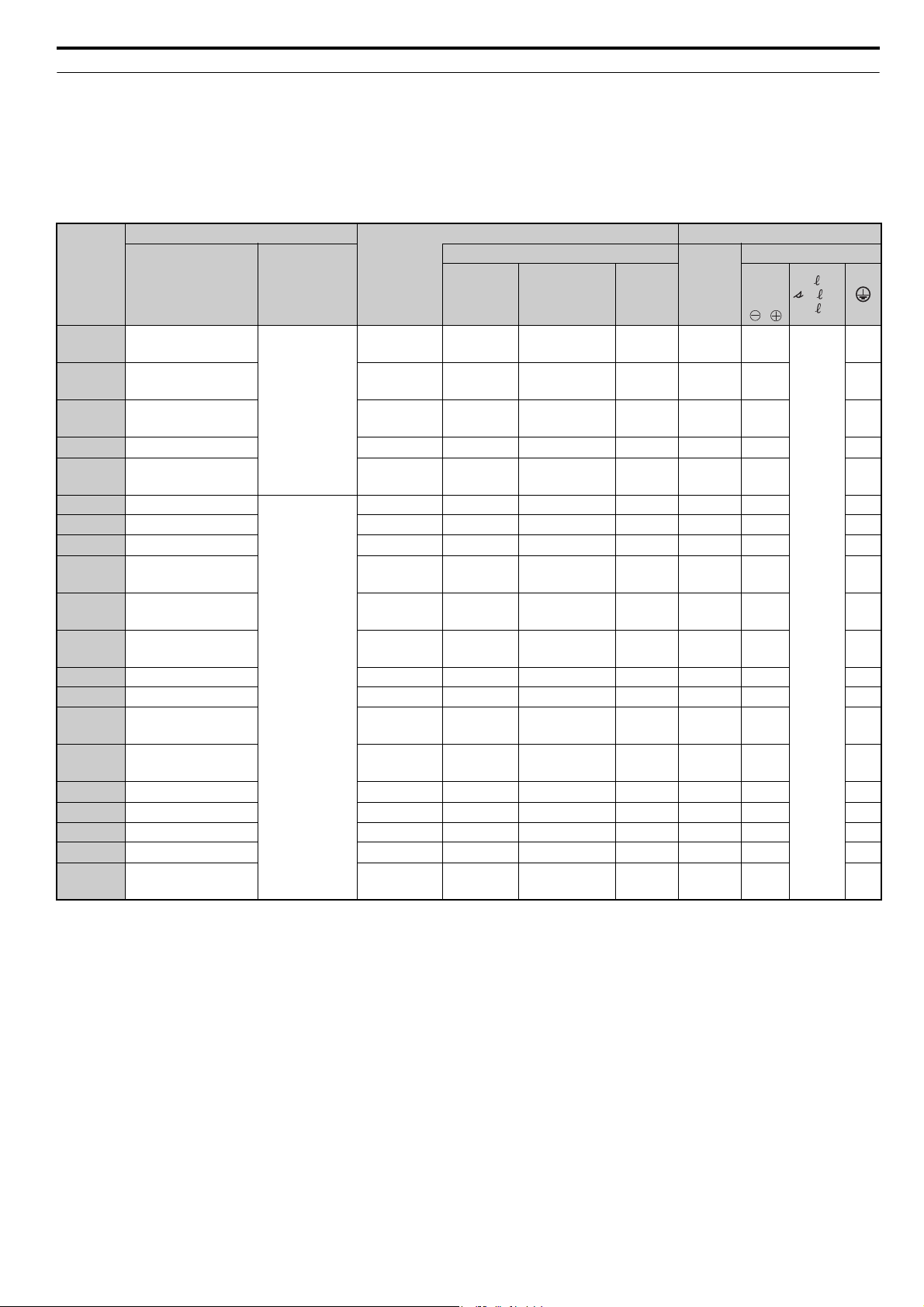
Table 2 Dimensions for IP20 Open Type Enclosure: 200 V Class
Model Figure
W H D W1 H0 H1 H2 H3 D1 t1 d
Dimensions mm
2A0005 1 180 300 187 160 – 284 8 – 75 5 M5 5
2A0010 1 180 300 187 160 – 284 8 – 75 5 M5 5
2A0020 2 220 365 197 192 350 335 8 15 78 5 M6 8
Weight
kg
Table 3 Dimensions for IP20 Open Type Enclosure: 400 V Class
Model Figure
W H D W1 H0 H1 H2 H3 D1 t1 d
4A0005 1 180 300 187 160 – 284 8 – 75 5 M5 5
4A0010 1 180 300 187 160 – 284 8 – 75 5 M5 5
4A0020 2 220 365 197 192 350 335 8 15 78 5 M6 8
Dimensions mm
Weight
kg
YASKAWA ELECTRIC TOEP C710656 06A YASKAWA Power Regenerative Converter - D1000 Quick Start Guide 13
Page 14

2 Mechanical Installation
W1
4-d
H1
H
H2
Max 10
W
t1
t1
D1
D
Figure 1
Max 10
D1
D
W
H1
H2
H
Max 6Max 6
6-d
t1
Figure 3
t1
W1
220 220
330 330
8-d
440
W1
H1
W
H2
Max 6
D
D1
t1
Max 6
H
t1
Figure 4
D1
D
t1
H1
H2
H
4-d
W1
W
Max 8Max 8
t1
Figure 2
IP00 Open Type Enclosure Models
Table 4 Dimensions for IP00 Open Type Enclosure: 200 V Class
Model Figure
2A0030 1 275 450 258 220 435 7.5 100 2.3 M6 20
W H D W1 H1 H2 D1 t1 d
Dimensions mm
2A0050 1 325 550 283 260 535 7.5 110 2.3 M6 32
2A0065 2 450 705 330 325 680 12.5 130 3.2 M10 57
2A0090 2 450 705 330 325 680 12.5 130 3.2 M10 61
2A0130 3 500 800 350 370 773 13 130 4.5 M12 85
Model Figure
Table 5 Dimensions for IP00 Open Type Enclosure: 400 V Class
Dimensions mm
W H D W1 H1 H2 D1 t1 d
4A0030 1 275 450 258 220 435 7.5 100 2.3 M6 21
4A0040 1 275 450 258 220 435 7.5 100 2.3 M6 21
4A0060 1 325 550 283 260 535 7.5 110 2.3 M6 34
4A0100 1 325 550 283 260 535 7.5 110 2.3 M6 36
4A0130 3 500 800 350 370 773 13 130 4.5 M12 85
4A0185 3 500 800 350 370 773 13 130 4.5 M12 85
4A0270 3 670 1140 370 440 1110 15 150 4.5 M12 183
4A0370 3 670 1140 370 440 1110 15 150 4.5 M12 194
4A0630 4 1250 1380 370 1100 1345 15 150 4.5 M12 413
Weight
kg
Weight
kg
14 YASKAWA ELECTRIC TOEP C710656 06A YASKAWA Power Regenerative Converter - D1000 Quick Start Guide
Page 15

3 Harmonic Filter Module Installation
C
A
B B B
3 Harmonic Filter Module Installation
Installation Environment
Install the harmonic filter module in an environment matching the specifications in Ta ble 6 to help prolong the optimum
performance life of the filter module.
Table 6 Installation Environment
Environment Conditions
Installation Area
Ambient
Temperature
Humidity 95% RH or less and free of condensation
Storage
Temperature
Surrounding Area
Altitude 3000 m or lower
Vibration
Indoors
Install the unit in an environment that does not easily accessible such as control panel.
IP00 Open Type enclosure: -10°C to +50°C
Filter module reliability improves in environments without wide temperature fluctuations.
When using the filter module in an enclosure panel, install a cooling fan or air conditioner in the area to ensure that the air
temperature inside the enclosure does not exceed the specified levels.
Do not allow ice to develop on the filter module.
-20°C to +60°C
Install the filter module in an area free from:
• oil mist and dust
• metal shavings, oil, water, or other foreign materials
• radioactive materials
• combustible materials (e.g., wood)
• harmful gases and liquids
• excessive vibration
• chlorides
• direct sunlight.
2
(20 to 55 Hz)
2.0 m/s
NOTICE: Prevent foreign matter such as metal shavings and wire clippings from falling into the unit and filter module during
installation. Failure to comply could result in damage to the unit and the filter module. Place a temporary cover over the top of the unit
and the filter module during installation. Remove the temporary cover before unit and filter module start-up, as the cover will reduce
ventilation and cause the unit and the filter module to overheat.
Installation Spacing
Figure 8 shows the installation distance required to maintain sufficient space for airflow and wiring.
Figure 7
A – 50 mm minimum C – 120 mm minimum
B – 30 mm minimum
Figure 8 Installation Spacing
YASKAWA ELECTRIC TOEP C710656 06A YASKAWA Power Regenerative Converter - D1000 Quick Start Guide 15
Page 16

3 Harmonic Filter Module Installation
A
Precautions and Instructions for Installation of Harmonic Filter Module
Read the following precautions and instructions before installing a harmonic filter module.
WARNING! Always observe the following precautions. If handled incorrectly, the harmonic filter module may fall, possibly causing
injury. Also, the harmonic filter module may be damaged.
• Suspend the harmonic filter module with wires only temporarily and only when installing them in a
control panel. Do not suspend them when transporting them.
• Before you suspend the harmonic filter module, confirm that faceplate, top cover, and other
configuration components are securely screwed in place.
• Do not place the harmonic filter module on its side.
• Do not leave the harmonic filter module suspended with wires for a long period of time.
Attach hooks to the specified locations when suspending the harmonic filter module with wires.
NOTICE: Do not apply excessive force to the top cover when suspending the harmonic filter.
The top cover may be deformed. When lifting the module by hand, always use the holding frames and use two people. Failure to
comply may damage the module.
Refer to Figure 9 and Figure 10 for details.
Figure 8
A
A
A
Figure 9
B
B
A – Suspension Holes (Two on Each Side) B – Holding Frames (One on Each Side)
Figure 9 Suspension Locations for the Harmonic Filter Module
Figure 10 Holding the Harmonic Filter Module
16 YASKAWA ELECTRIC TOEP C710656 06A YASKAWA Power Regenerative Converter - D1000 Quick Start Guide
Page 17

Harmonic Filter Module Dimensions
W1
W
H
D1
D
D2
4-d
Figure 1
W
H
±
5
W1
D
4-d
D1
D2
Figure 2
WD
H
±
5
W1 D1 4-dD2
Figure 3
D1000
3 Harmonic Filter Module Installation
Table 7 Dimensions for IP00 Open Type Enclosure: 200 V Class
Model Figure
W H D W1 D1 D2 d
Dimensions mm
EUJ71080 1 209 176 285 160 240 39 M6 6.5
EUJ71081 1 209 184 295 160 250 39 M6 9
EUJ71082 2 232 265 301 203 247 44 M8 14
EUJ71083 2 260 281 305 220 256 39 M8 16
EUJ71084 2 290 348 355 250 314 30 M10 27
EUJ71085 3 290 350 352 254 314 27 M10 38
EUJ71086 3 290 387 352 254 314 27 M10 43
EUJ71087 3 350 500 380 290 350 19 M10 62
Weight
kg
Table 8 Dimensions for IP00 Open Type Enclosure: 400 V Class
Model Figure
W H D W1 D1 D2 d
Dimensions mm
EUJ71088 1 209 176 285 160 240 39 M6 7
EUJ71089 1 209 178 295 160 250 39 M6 9
EUJ71090 2 232 265 301 203 247 44 M8 15
EUJ71091 2 260 293 305 220 256 39 M8 17
EUJ71092 2 260 293 305 220 256 39 M8 19
EUJ71093 2 290 348 355 250 314 30 M10 27
EUJ71094 2 290 385 355 250 314 30 M10 39
EUJ71095 3 350 500 380 290 350 19 M10 64
EUJ71096 3 350 500 380 290 344 25 M10 73
Weight
kg
YASKAWA ELECTRIC TOEP C710656 06A YASKAWA Power Regenerative Converter - D1000 Quick Start Guide 17
Page 18

4 Electrical Installation
M
D1000
+
-
r1/
11
1/
21
t1/
31
S1
S2
S3
S4
S5
S6
S7
S8
E(G)
RUN-SB
External fault
Fault reset
(Reserved)
(Reserved)
(Reserved)
External
Baseblock
Shield ground terminal
STOP
VI
MEMOBUS/
Modbus comm.
RS-422/RS-485
max. 115.2 kbps
+
1
-
Converter
Drive
Motor
Multi-function
digital inputs
(default setting)
+V
A1
A2
A3
AC
(Reserved)
(Reserved)
(Reserved)
Control Circuit
-V
Analog Input 1
Analog Input 2
Analog Input 3
DIP Switch S1
Termination resistor
(120 Ω, 1/2 W)
DIP
Switch S2
R+
R-
S+
S-
IG
ThreePhase
Power
Supply
Input AC
<2><3>
reactor
Harmonic filter module
<3>
U
V
W
X
Y
Z
R/L1
S/L2
T/L3
RCD
or
MCCB
X
Y
Z
R/L1
S/L2
T/L3
r
t
CN5-A
CN5-B
CN5-C
Option card
connectors
Ground
Sink
Power supply
+10.5 Vdc, max. 20 mA
Power supply, -10.5 Vdc,
max. 20 mA
<7>
<4><5>
<1>
<4><5>
MA
MB
MC
Fault relay output
250 Vac, max. 1 A
30 Vdc, max 1 A
(min. 5 Vdc, 10 mA)
Multi-function relay output
(During MC on)
250 Vac, max. 1 A
30 Vdc, max 1 A
(min. 5 Vdc, 10 mA)
Multi-function relay output
(Converter Ready)
250 Vac, max. 1 A
30 Vdc, max 1 A
(min. 5 Vdc, 10 mA)
Multi-function relay
output (During Run)
<6>
250 Vac, max. 1 A
30 Vdc, max 1 A
(min. 5 Vdc, 10 mA)
M1
M2
M3
M4
M5
M6
0 V
FM
AM
AC
E (G)
<9>
<9>
Multi-function analog
output 1
(Output frequency)
-10 to +10 Vdc (2mA) or
4 to 20 mA
Multi-function analog
output 2
(Output current)
-10 to +10 Vdc (2mA) or
4 to 20 mA
FM
AM
SC
+24 V
Sink / Source mode
selection wire link
(default: Sink)
SP
SN
<8>
shielded line twisted-pair shielded line
main circuit terminal control circuit terminal
−
+
−
+
YEU
4 Electrical Installation
The figure below shows the main and control circuit wiring.
Figure 10
<1> NOTICE: When installing a noise filter on the converter power supply, use a reactor-type noise filter (without a capacitor), such as
a zero phase reactor, and install it after the MCCB on the power supply side. Do not install a filter with a built-in capacitor as the
harmonic components may cause the capacitor to overheat or may damage the capacitor.
Figure 11 Standard Connection Diagram (example: model 2A0030, 2A0130, 4A0030 to 4A0185)
<2> Do not use a line longer than 10 m to connect the input AC reactor and the converter.
<3> Use the specified AC reactor and harmonic filter module. Non-specified devices may cause erroneous operation.
<4> Do not use a DC bus line that is longer than 5 m to connect the converter and drive.
<5> NOTICE: When installing a breaker or contactor on the converter side for an emergency shutoff, confirm that the CHARGE
indicators on the drive and converter are not lit before closing the breaker or contactor on the converter output (DC) side. If the
power supply is turned on while there is a voltage charge, an overcurrent will flow and the device may be damaged. Always
confirm that the breaker or contactor on the unit output (DC) side is turned on before applying power to the converter.
<6> Sequence the operation so that the converter starts operation before the drive when power is applied. Sequence the stopping
operation to turn off the drive first, then the motor, and finally the converter. Operating the drive without operating the converter or
turning off the power supply unit during operation may trigger a converter fault.
<7> Do not connect a power supply to the drive AC power supply terminals (R/L1, S/L2, and T/L3).
<8> The connections are shown for sequence connections with no-voltage contacts or NPN transistors for the sequence input signals
(S1 to S8). Use jumper S3 to select between Sink mode and Source mode. The default setting is Sink mode.
<9> Multi-function analog outputs work with devices such as analog frequency meters, ammeters, voltmeters, and wattmeters. They are
not intended for use as a feedback-type signal.
18 YASKAWA ELECTRIC TOEP C710656 06A YASKAWA Power Regenerative Converter - D1000 Quick Start Guide
Page 19

Figure 11
M
D1000
+
-
r1/
11
1/
21
t1/
31
S1
S2
S3
S4
S5
S6
S7
S8
E(G)
+
1
-
Converter
Motor
+V
A1
A2
A3
AC
Control Circuit
-V
R/L1
S/L2
T/L3
CN5-A
CN5-B
CN5-C
Option card
connectors
U
V
W
X
Y
Z
U
V
W
X
Y
Z
Harmonic filter
reactor
UVW
E
UVW
XYZ
Harmonic filter
condencer
Sink
Drive
RUN-SB
External fault
Fault reset
(Reserved)
(Reserved)
(Reserved)
External
Baseblock
STOP
MEMOBUS/
Modbus comm.
RS-422/RS-485
max. 115.2 kbps
(Reserved)
(Reserved)
(Reserved)
VI
DIP Switch S1
Termination resistor
(120 Ω, 1/2 W)
DIP
Switch S2
R+
R-
S+
S-
IG
ThreePhase
Power
Supply
Input AC
reactor 2
RCD
or
MCCB
Ground
Shield ground terminal
Analog Input 1
Analog Input 2
Analog Input 3
Power supply
+10.5 Vdc, max. 20 mA
Power supply, -10.5 Vdc,
max. 20 mA
<7>
<3>
<1>
<4><5>
<4><5>
Multi-function
digital inputs
(default setting)
Input AC
<2><3>
reactor 1
shielded line twisted-pair shielded line
main circuit terminal control circuit terminal
MA
MB
MC
Fault relay output
250 Vac, max. 1 A
30 Vdc, max 1 A
(min. 5 Vdc, 10 mA)
Multi-function relay output
(During MC on)
250 Vac, max. 1 A
30 Vdc, max 1 A
(min. 5 Vdc, 10 mA)
Multi-function relay output
(Converter Ready)
250 Vac, max. 1 A
30 Vdc, max 1 A
(min. 5 Vdc, 10 mA)
Multi-function relay
output (During Run)
<6>
250 Vac, max. 1 A
30 Vdc, max 1 A
(min. 5 Vdc, 10 mA)
M1
M2
M3
M4
M5
M6
0 V
FM
AM
AC
E (G)
<9>
<9>
Multi-function analog
output 1
(Output frequency)
-10 to +10 Vdc (2mA) or
4 to 20 mA
Multi-function analog
output 2
(Output current)
-10 to +10 Vdc (2mA) or
4 to 20 mA
FM
AM
SC
+24 V
Sink / Source mode
selection wire link
(default: Sink)
SP
SN
<8>
−
+
−
+
YEU
4 Electrical Installation
<1> NOTICE: When installing a noise filter on the converter power supply, use a reactor-type noise filter (without a capacitor), such as
a zero phase reactor, and install it after the MCCB on the power supply side. Do not install a filter with a built-in capacitor as the
harmonic components may cause the capacitor to overheat or may damage the capacitor.
<2> Do not use a line longer than 10 m to connect the input AC reactor and the converter.
<3> Use the specified AC reactor and harmonic filter module. Non-specified devices may cause erroneous operation.
<4> Do not use a DC bus line that is longer than 5 m to connect the converter and drive.
<5> NOTICE: When installing a breaker or contactor on the converter side for an emergency shutoff, confirm that the CHARGE
indicators on the drive and converter are not lit before closing the breaker or contactor on the converter output (DC) side. If the
power supply is turned on while there is a voltage charge, an overcurrent will flow and the device may be damaged. Always
confirm that the breaker or contactor on the unit output (DC) side is turned on before applying power to the converter.
<6> Sequence the operation so that the converter starts operation before the drive when power is applied. Sequence the stopping
operation to turn off the drive first, then the motor, and finally the converter. Operating the drive without operating the converter or
turning off the power supply unit during operation may trigger a converter fault.
<7> Do not connect a power supply to the drive AC power supply terminals (R/L1, S/L2, and T/L3).
<8> The connections are shown for sequence connections with no-voltage contacts or NPN transistors for the sequence input signals
(S1 to S8). Use jumper S3 to select between Sink mode and Source mode. The default setting is Sink mode.
<9> Multi-function analog outputs work with devices such as analog frequency meters, ammeters, voltmeters, and wattmeters. They are
not intended for use as a feedback-type signal.
Figure 12 Standard Connection Diagram (example: model 4A0270, 4A0370)
YASKAWA ELECTRIC TOEP C710656 06A YASKAWA Power Regenerative Converter - D1000 Quick Start Guide 19
Page 20

4 Electrical Installation
r
YEU
Figure 12
ThreePhase
Power
Supply
RCD
or
MCCB
<1>
Input AC
reactor 2
U
V
W
Harmonic filter
reactor
<3>
Harmonic filter
condencer
Multi-function
digtial inputs
(default setting)
X
Y
Z
UV
W
X
Y
Z
UV W
RUN-SB
STOP
External fault
Fault reset
(Reserved)
(Reserved)
(Reserved)
External
Baseblock
(Reserved)
(Reserved)
(Reserved)
Input AC
reactor 1
U
V
W
Input AC
reactor 1
U
V
W
E
Sink / Source mode
selection wire link
(default: Sink)
<8>
<2><3>
X
Y
Z
X
Y
Z
R/L1
S/L2
T/L3
R1/L11
S1/L21
T1/L31
r1/ 11
1/ 21
t1/ 31
Control Circuit
S1
S2
S3
S4
S5
S6
S7
S8
Sink
SN
SC
SP
+24 V
E(G)
Shield ground terminal
Power supply
+10.5 Vdc, max. 20 mA
+V
Analog Input 1
A1
A2
Analog Input 2
Analog Input 3
A3
AC
Converter
D1000
Option card
connectors
CN5-C
CN5-B
CN5-A
Multi-function relay
output (During Run)
250 Vac, max. 1 A
30 Vdc, max 1 A
(min. 5 Vdc, 10 mA)
Multi-function relay output
(During MC on)
250 Vac, max. 1 A
30 Vdc, max 1 A
(min. 5 Vdc, 10 mA)
Multi-function relay output
(Converter Ready)
250 Vac, max. 1 A
30 Vdc, max 1 A
(min. 5 Vdc, 10 mA)
Fault relay output
250 Vac, max. 1 A
30 Vdc, max 1 A
(min. 5 Vdc, 10 mA)
DIP Switch S1
VI
<6>
+
<4><5>
-
<4><5>
Ground
1
+
<7>
-
Moto
IM
Drive
M1
M2
M3
M4
M5
M6
MA
MB
MC
-V
Power supply, -10.5 Vdc,
max. 20 mA
Termination resistor
(120 Ω, 1/2 W)
DIP
Switch S2
MEMOBUS/
Modbus comm.
RS-422/RS-485
max. 115.2 kbps
R+
R-
S+
S-
IG
shielded line twisted-pair shielded line
main circuit terminal control circuit terminal
Figure 13 Standard Connection Diagram (example: model CIMR-D4A0630)
Multi-function analog
output 1
(Output frequency)
-10 to +10 Vdc (2mA) or
4 to 20 mA
<9>
Multi-function analog
output 2
(Output current)
-10 to +10 Vdc (2mA) or
4 to 20 mA
<9>
FM
AM
AC
0 V
E (G)
+
−
FM
+
−
AM
<1> NOTICE: When installing a noise filter on the converter power supply, use a reactor-type noise filter (without a capacitor), such as
a zero phase reactor, and install it after the MCCB on the power supply side. Do not install a filter with a built-in capacitor as the
harmonic components may cause the capacitor to overheat or may damage the capacitor.
<2> Do not use a line longer than 10 m to connect the input AC reactor and the converter.
<3> Use the specified AC reactor and harmonic filter module. Non-specified devices may cause erroneous operation.
<4> Do not use a DC bus line that is longer than 5 m to connect the converter and drive.
<5> NOTICE: When installing a breaker or contactor on the converter side for an emergency shutoff, confirm that the CHARGE
indicators on the drive and converter are not lit before closing the breaker or contactor on the converter output (DC) side. If the
power supply is turned on while there is a voltage charge, an overcurrent will flow and the device may be damaged. Always
confirm that the breaker or contactor on the unit output (DC) side is turned on before applying power to the converter.
<6> Sequence the operation so that the converter starts operation before the drive when power is applied. Sequence the stopping
operation to turn off the drive first, then the motor, and finally the converter. Operating the drive without operating the converter or
turning off the power supply unit during operation may trigger a converter fault.
<7> Do not connect a power supply to the drive AC power supply terminals (R/L1, S/L2, and T/L3).
<8> The connections are shown for sequence connections with no-voltage contacts or NPN transistors for the sequence input signals
(S1 to S8). Use jumper S3 to select between Sink mode and Source mode. The default setting is Sink mode.
<9> Multi-function analog outputs work with devices such as analog frequency meters, ammeters, voltmeters, and wattmeters. They are
not intended for use as a feedback-type signal.
20 YASKAWA ELECTRIC TOEP C710656 06A YASKAWA Power Regenerative Converter - D1000 Quick Start Guide
Page 21
4 Electrical Installation
Wiring Specification
Main Circuit
Use the EMC filters and the harmonic filter modules listed in the table below when wiring the main circuit. Make sure
not to exceed the given tightening torque values.
Table 9 Wiring Specification (Main Circuit, EMC Filter, and Harmonic Filter Module)
EMC Filter Type
Model
CIMR-D
2A0005
2A0010 RTEN-2030C6E3-00 EUJ71081
2A0020 RTEN-2080G6E2-00 EUJ71082
2A0030 RTEN-2100G6E3-00 EUJ71083 170M1371 BUSSMANN 250 25 M8 16
2A0050 RTEN-2150G6E2-00 EUJ71084
2A0065 B84143B0320T176
2A0090 B84143B0320T176 EUJ71086 170M4016 BUSSMANN 630 95 × 2P M12 95
2A0130 B84143B0400T176 EUJ71087 170M4017 BUSSMANN 700 95 × 2P M12 95
4A0005 B84143A0020R106 EUJ71088
4A0010 B84143A0020R106 EUJ71089
4A0020 B84143A0035R106 EUJ71090
4A0030 B84143A0065R106 EUJ71091 170M1369 BUSSMANN 160 10 M8 10
4A0040 B84143A0065R106 EUJ71092 170M1370 BUSSMANN 200 16 M8 16
4A0060 B84143B0180S080 EUJ71093
4A0100 B84143B0180S080 EUJ71094
4A0130 B84143B0400S080 EUJ71095 170M4012 BUSSMANN 400 95 M10 50
4A0185 B84143B0400S080 EUJ71096 170M4015 BUSSMANN 550 95 × 2P M12 95
4A0270 B84143B1000S080 – 170M6014 BUSSMANN 1000 95 × 2P M12 95
4A0370 B84143B1000S080 – 170M6016 BUSSMANN 1250 150 × 2P M12 150
4A0630 B84143B1600S080 – 170M6016 BUSSMANN 1250 150 × 2P M12
Model Manufacturer
RTEN-2030C6E3-00
TDK-Lambda
EPCOS
Harmonic
Filter
Module
EUJ71080
EUJ71085 170M4015 BUSSMANN 550 95 M12 50
Model Manufacturer
350GH-
32ULTC
350GH-
50ULTC
350GH-
125ULTC
350GH-
250ULTC
660GH-
16ULTC
660GH-
40ULTC
660GH-
63ULTC
660GH-
200ULTC
660GH-
315ULTC
Fuse
Rating
Ampere
(A)
HINODE 32 4 M4
HINODE 50 4 M4 4
HINODE 125 16 M6 16
HINODE 250 50 M8 25
HINODE 16 4 M4 0.75
HINODE 40 4 M4 2.5
HINODE 63 2.5 M6 2.5
HINODE 200 25 M8 16
HINODE 315 50 M8 25
Recom.
Cable
(mm2)
Main Circuit
Terminal Sizes
R/L1,
S/L2,
T/L3,
,
r1/ 11,
1/ 21,
t1/ 31
2.5
1.5
150 ×
2P
<1> Connect two of the same filters in parallel. Refer to the Technical Manual for details.
<2> DC Power Supply Input is not available for UL standards.
<3> Manufacturer does not recommend a specific fuse holder for this fuse. Contact Yaskawa or your nearest sales representative on fuse
dimensions.
YASKAWA ELECTRIC TOEP C710656 06A YASKAWA Power Regenerative Converter - D1000 Quick Start Guide 21
Page 22

4 Electrical Installation
CE Standards Compliance for DC Power Supply Input
Factory Recommended Branch Circuit Protection
Install appropriate harmonic filter module that has built-in input fuses to the input side to protect converter wiring and
prevent other secondary damage. Select harmonic filter module according to Tabl e 9.
Refer to the Technical Manual for details on the converter Input Current and Rated Output Current.
NOTICE: If a fuse is blown or a Residual Current Device (RCD) is tripped, check the wiring and the selection of peripheral devices to
identify the cause. Contact Yaskawa before restarting the drive or the peripheral devices if the cause cannot be identified.
Harmonic Filter Module
Table 10 Wire Gauge and Torque Specifications (Harmonic Filter Module)
Model Terminal
R/L1, S/L2, T/L3
EUJ71080
EUJ71081
EUJ71082
EUJ71083
EUJ71084
EUJ71085
EUJ71086
EUJ71087
EUJ71088
EUJ71089
r, , t 2.5 2.5
R/L1, S/L2, T/L3
X, Y, Z
r, , t 2.5 2.5 M4 1.1 to 1.2
R/L1, S/L2, T/L3
X, Y, Z 16 to 25
r, , t 2.5 2.5 M4 1.1 to 1.2
R/L1, S/L2, T/L3
X, Y, Z 25 to 35
r, , t 2.5 2.5 to 6 M4 1.1 to 1.2
R/L1, S/L2, T/L3
X, Y, Z
r, , t 2.5 2.5 to 6 M4 1.1 to 1.2
R/L1, S/L2, T/L3
X, Y, Z 95
r, , t 2.5 2.5 to 6 M4 1.1 to 1.2
R/L1, S/L2, T/L3
X, Y, Z 95
r, , t 2.5 2.5 to 6 M4 1.1 to 1.2
R/L1, S/L2, T/L3
X, Y, Z
r, , t 2.5 2.5 to 6 M4 1.1 to 1.2
R/L1, S/L2, T/L3
r, , t 2.5 2.5
R/L1, S/L2, T/L3
r, , t 2.5 2.5
Recommended Gauge
200 V Class
400 V Class
2
mm
4
1.5 1.5 to 6 M5 2.2 to 2.4
4 4 to 10 M5 2.2 to 2.4
4 4 to 6 M5 2.2 to 2.4
16
16 10 to 16 M6 4 to 5
25
16 16 to 25 M8 8.9 to 10.7
50 50 to 70 M8 8.9 to 10.7
25 25 M8 8.9 to 10.7
95
50 35 to 50 M12 32 to 40
95 × 2P
95 70 to 95 M12 32 to 40
95 × 2P 95 to 150 M12 32 to 40
95 70 to 95 M12 32 to 40
4
0.75 0.75 to 4 M5 2.2 to 2.4
4
2.5 2.5 to 6 M5 2.2 to 2.4
Applicable
Gauge
2
mm
4 to 10
16 to 70
25 to 70
95 to 150
95 to 150
4 to 10
4 to 10
Screw
Size
M4 1.1 to 1.2X, Y, Z 4
M6 4 to 5
M8 8.9 to 10.7
M12 32 to 40
M12 32 to 40
M4 1.1 to 1.2X, Y, Z 4
M4 1.1 to 1.2X, Y, Z 4
Tightening
Tor que
Nxm
22 YASKAWA ELECTRIC TOEP C710656 06A YASKAWA Power Regenerative Converter - D1000 Quick Start Guide
Page 23

4 Electrical Installation
Model Terminal
R/L1, S/L2, T/L3
EUJ71090
EUJ71091
EUJ71092
EUJ71093
EUJ71094
EUJ71095
EUJ71096
X, Y, Z 6 to 25
r, , t 2.5 2.5 M4 1.1 to 1.2
R/L1, S/L2, T/L3
X, Y, Z 10 to 35
r, , t 2.5 2.5 to 6 M4 1.1 to 1.2
R/L1, S/L2, T/L3
X, Y, Z 16 to 35
r, , t 2.5 2.5 to 6 M4 1.1 to 1.2
R/L1, S/L2, T/L3
X, Y, Z
r, , t 2.5 2.5 to 6 M4 1.1 to 1.2
R/L1, S/L2, T/L3
X, Y, Z
r, , t 2.5 2.5 to 6 M4 1.1 to 1.2
R/L1, S/L2, T/L3
X, Y, Z
r, , t 2.5 2.5 to 6 M4 1.1 to 1.2
R/L1, S/L2, T/L3
X, Y, Z
r, , t 2.5 2.5 to 6 M4 1.1 to 1.2
Recommended Gauge
2
mm
6
6 6 to 10 M6 4 to 5
10
10 10 to 16 M8 8.9 to 10.7
16
16 16 M8 8.9 to 10.7
25 25 to 70 M8 8.9 to 10.7
16 16 M8 8.9 to 10.7
50 50 to 70 M8 8.9 to 10.7
25 25 M8 8.9 to 10.7
95 95 M12 32 to 40
50 50 to 70 M12 32 to 40
95 × 2P 95 M12 32 to 40
95 50 to 95 M12 32 to 40
Applicable
Gauge
2
mm
6 to 70
10 to 70
16 to 70
Screw
Size
M6 4 to 5
M8 8.9 to 10.7
M8 8.9 to 10.7
Tightening
Tor que
Nxm
Control Circuit
The control terminal board is equipped with screwless terminals. Always use wires within the specification listed below.
For safe wiring it is recommended to use solid wires or flexible wires with ferrules. The stripping length respectively
ferrule length should be 8 mm.
Wire Type Wire Size (mm2)
Solid 0.2 to 1.5
Flexible 0.2 to 1.0
Flexible with ferrule 0.25 to 0.5
YASKAWA ELECTRIC TOEP C710656 06A YASKAWA Power Regenerative Converter - D1000 Quick Start Guide 23
Page 24

4 Electrical Installation
D1000
+
-
(Ground)
Converter
Input AC
reactor
U
V
W
X
Y
Z
R/L1
S/L2
T/L3
RCD
or
MCCB
Harmonic
Filter Module
X
Y
Z
t
r
R/L1
S/L2
T/L3
A1000
Drive
+
R/L1
S/L2
T/L3
-
IM
U/T1
V/T2
W/T3
Motor
Line
filter
PE
Ground
r1/ 11
1/ 21
t1/ 31
ThreePhase
Power
Supply
shielded line twisted-pair shielded line
main circuit terminal control circuit terminal
YEU
D1000
+
-
U
V
W
X
Y
Z
R/L1
S/L2
T/L3
A1000
+
R/L1
S/L2
T/L3
-
IM
U/T1
V/T2
W/T3
PE
U
V
W
X
Y
Z
Harmonic filter
reactor
UVW
UVW
X
YZ
Harmonic filter
condencer
E
r1/ 11
1/ 21
t1/ 31
(Ground)
Converter
Input AC
reactor 1
RCD
or
MCCB
Input AC
reactor 2
Drive
Motor
Line
filter
Ground
ThreePhase
Power
Supply
shielded line twisted-pair shielded line
main circuit terminal control circuit terminal
YEU
EMC Filter Installation
The following conditions must be met to ensure continued compliance with guidelines. Refer to the Technical Manual for
EMC filter selection.
Installation Method
Verify the following installation conditions to ensure that other devices and machinery used in combination with this
drive also comply with EMC guidelines.
1.
Install an EMC noise filter to the input side specified by Yaskawa for compliance with European standards.
2. Place the drive and EMC noise filter in the same enclosure.
3. Use braided shield cable for the drive and motor wiring, or run the wiring through a metal conduit.
4. Keep wiring as short as possible. Ground the shield on both the drive side and the motor side.
5. Make sure the protective earthing conductor complies with technical standards and local safety regulations.
Connection Diagram
Figure 13
Figure 14
Figure 14 Wiring Diagram for EMC Filter (Models 2A0005 to 2A0130, 4A0005 to 4A0185)
Figure 15 Wiring Diagram for EMC Filter (Models 4A0270, 4A0370)
24 YASKAWA ELECTRIC TOEP C710656 06A YASKAWA Power Regenerative Converter - D1000 Quick Start Guide
Page 25

4 Electrical Installation
EMC Filters
The converter should be installed with the EMC filters listed in Tabl e 11 in order to comply with the IEC/EN61800-3
requirements.
Table 11 IEC/EN61800-3 Filters
Model Type Manufacturer
2A0005 RTEN-2030C6E3-00 TDK-Lambda 30 1.1 170 × 54 × 90 80 × 160
2A0010 RTEN-2030C6E3-00 TDK-Lambda 30 1.1 170 × 54 × 90 80 × 160
2A0020 RTEN-2080G6E2-00 TDK-Lambda 80 3.9 267 × 85 × 161 135 × 247
2A0030 RTEN-2100G6E3-00 TDK-Lambda 100 5.1 285 × 79 × 152 126 × 265
2A0050 RTEN-2150G6E2-00 TDK-Lambda 150 6.5 290 × 88 × 190 164 × 270
2A0065 B84143B0320T176 EPCOS 320 20.7 605 × 140 × 220 200 × 450
2A0090 B84143B0320T176 EPCOS 320 20.7 605 × 140 × 220 200 × 450
2A0130 B84143B0400T176 EPCOS 400 20.9 605 × 140 × 220 200 × 450
4A0005 B84143A0020R106 EPCOS 20 0.6 150 × 58 × 57.5 28 × 132.5
4A0010 B84143A0020R106 EPCOS 20 0.6 150 × 58 × 57.5 28 × 132.5
4A0020 B84143A0035R106 EPCOS 35 0.9 200 × 71 × 72.5 50 × 142.5
4A0030 B84143A0065R106 EPCOS 65 1.9 217 × 80 × 84.5 65 × 152.5
4A0040 B84143A0065R106 EPCOS 65 1.9 217 × 80 × 84.5 65 × 152.5
4A0060 B84143B0180S080 EPCOS 180 5 270 × 114 × 170 155 × 145
4A0100 B84143B0180S080 EPCOS 180 5 270 × 114 × 170 155 × 145
4A0130 B84143B0400S080 EPCOS 400 7.5 320 × 120 × 190 165 × 170
4A0185 B84143B0400S080 EPCOS 400 7.5 320 × 120 × 190 165 × 170
4A0270 B84143B1000S080 EPCOS 1000 18.5 410 × 140 × 260 235 × 240
4A0370 B84143B1000S080 EPCOS 1000 18.5 410 × 140 × 260 235 × 240
4A0630 B84143B1600S080 EPCOS 1600 24.5 490 × 140 × 260 235 × 240
Rated Current
(A)
Weight
kg
Dimensions
[W × H × D] mm
Y × X
mm
Main Circuit Terminal Functions
Table 12 Main Circuit Terminal Functions
Terminal Typ e
Model
R/L1
S/L2
T/L3
r1/ 11
1/ 21
t1/ 31
Power supply voltage detection inputs
2A0005 to 2A0130
4A0005 to 4A0630
Main circuit power supply input
DC voltage output These terminals output a DC voltage
For 200 V class: 100 Ω or less
For 400 V class: 10 Ω or less
Function
These are the power supply input terminals that connect to the
input reactor.
These terminals are to detect the power supply voltage order and
voltage levels.
Grounding terminal
YASKAWA ELECTRIC TOEP C710656 06A YASKAWA Power Regenerative Converter - D1000 Quick Start Guide 25
Page 26

4 Electrical Installation
㪤㪘 㪤㪙 㪤㪚
㪤㪊 㪤㪋 㪤㪍
㪤㪈 㪤㪉 㪤㪌
㪛㪤㪄
㪠㪞 㪩㪂 㪩㪄 㪪㪂 㪪㪄㪟㪚 㪟㪈 㪟㪉
㪛㪤㪂
㪜㩿㪞㪀
㪘㪊 㪝㪤 㪘㪤 㪘㪚 㪤㪧 㪩㪧 㪘㪚㪘㪚 㪭㪄 㪘㪈 㪘㪉㪭㪂
㪪㪈 㪪㪉 㪪㪊 㪪㪋 㪪㪌 㪪㪍 㪪㪎 㪪㪥 㪪㪚 㪪㪧
㪪㪏
MA MB MC
M3 M4 M6
M1 M2 M5
A3 FM AM AC MP RP ACAC V- A1 A2V+
S1 S2 S3 S4 S5 S6 S7 SN SC SP
S8
DM-
IG R+ R- S+ S-HC H1 H2
DM+
E(G)
YEU
V
I
V
I
Current Voltage
AM
FM
V
I
V
I
AM
FM
FM/AM: Voltage Output FM: Current Output
AM: Voltage Output
...
Control Circuit Terminals
The control circuit terminals are arranged as shown in Figure 16.
Figure 15
Figure 16 Control Circuit Terminal Arrangement
There are three DIP Switches and one Slide Switch and two jumpers, S1 to S6, located on the terminal board.
S1 Terminal A2 Signal Selection
S2 RS-422/RS-485 Termination Resistor
S5 Terminal FM/AM Signal Selection
Off
On
26 YASKAWA ELECTRIC TOEP C710656 06A YASKAWA Power Regenerative Converter - D1000 Quick Start Guide
Page 27

4 Electrical Installation
Control Circuit Terminal Functions
Table 13 Control Circuit Input Terminals
Type No. Terminal Name (Function) Function (Signal Level) Default Setting
S1 Multi-function input 1 (RUN-SB)
S2 Multi-function input 2 (STOP)
Multi-Function
Digital Inputs
Analog Inputs
S3 Multi-function input 3 (External fault)
S4 Multi-function input 4 (Fault reset)
S5 Multi-function input 5 (Reserved)
S6 Multi-function input 6 (Reserved)
S7 Multi-function input 7 (Reserved)
S8 Multi-function input 8 (External Baseblock)
SC Multi-function input common
SP Digital input power supply +24 Vdc 24 Vdc power supply for digital inputs, 150 mA max (only
SN Digital input power supply 0 V
+V Analog reference input 10.5 Vdc (max allowable current 20 mA)
-V Analog reference input -10.5 Vdc (max allowable current 20 mA)
A1 Multi-function analog input 1 (Reserved) -10 to 10 Vdc, 0 to 10 Vdc (input impedance: 20 kΩ)
A2 Multi-function analog input 2 (Reserved)
A3 Multi-function analog input 3 (Reserved)
AC Frequency reference common 0 V
E(G) Ground for shielded lines and option cards –
• Photocoupler
• 24 Vdc, 8 mA
• Set the S3 jumper to select between sinking, sourcing mode,
and the power supply.
when not using digital input option DI-A3)
NOTICE: Do not jumper or short terminals SP and SN.
Failure to comply will damage the converter.
• -10 to 10 Vdc, 0 to 10 Vdc (input impedance: 20 kΩ)
• 4 to 20 mA, 0 to 20 mA (input impedance: 250 Ω)
• Voltage or current input must be selected by DIP switch S1
and H3-09.
• -10 to 10 Vdc, 0 to 10 Vdc (input impedance: 20 kΩ)
• Use DIP switch S4 on the terminal board to select between
analog and PTC input.
Table 14 Control Circuit Output Terminals
Typ e
Fault Relay
Output
Multi-Function
Digital
Output
<1>
Monitor Output
<1> Refrain from assigning functions to digital relay outputs that involve frequent switching, as doing so may shorten relay performance life.
Switching life is estimated at 200,000 times (assumes 1 A, resistive load).
No. Terminal Name (Function) Function (Signal Level) Default Setting
MA N.O. output (Fault)
MB N.C. output (Fault)
MC Fault output common
M1
M2
M3
M4
M5
M6
FM
AM
AC Monitor common 0 V
Multi-function digital output (During Run 1)
Multi-function digital output (During MC on)
Multi-function digital output (Converter Ready)
Analog monitor output 1 (Power Supply Side
Power)
Analog monitor output 2 (Power Supply Side
Current)
30 Vdc, 10 mA to 1 A; 250 Vac, 10 mA to 1 A
Minimum load: 5 Vdc, 10 mA
30 Vdc, 10 mA to 1 A; 250 Vac,
10 mA to 1 A
Minimum load: 5 Vdc, 10 mA
30 Vdc, 10 mA to 1 A; 250 Vac,
10 mA to 1 A
Minimum load: 5 Vdc, 10 mA
-10 to +10 Vdc, or 0 to +10 Vdc
YASKAWA ELECTRIC TOEP C710656 06A YASKAWA Power Regenerative Converter - D1000 Quick Start Guide 27
Page 28

5 Using the Digital Operator
YEU
F2
F2
F2
F2
F1
F1
F1
5 Using the Digital Operator
LCD Display
Figure 16
123
- MODE -
DRV
Rdy
Volt Ref (OPR)
U1-51= 330V
U1-52= 330V
U1-53= 0.00A
Figure 17 LCD Display
Table 15 Display and Contents
No. Name Display Content
MODE Displayed when in Mode Selection.
MONITR Displayed when in Monitor Mode.
1 Operation Mode Menus
2Mode Display Area
3 Ready Rdy Indicates the drive is ready to run.
4 Data Display – Displays specific data and operation data.
DC Bus Voltage
5
6
Reference
Assignment
LO/RE
Display
<1>
<2>
VERIFY Indicates the Verify Menu.
PRMSET Displayed when in Parameter Setting Mode.
SETUP Displayed when in Setup Mode.
DRV Displayed when in Drive Mode.
PRG Displayed when in Programming Mode.
OPR Displayed when the DC Bus Voltage Reference is assigned to the LCD Operator Option.
AI Displayed when the DC Bus Voltage Reference is assigned to the drives Analog Input.
COM
OP Displayed when the DC Bus Voltage Reference is assigned to a drive Option Unit.
RSEQ Displayed when the reference is supplied from a remote source.
LSEQ Displayed when the reference is supplied from the operator keypad.
RREF Displayed when the frequency reference is supplied from a remote source.
LREF Displayed when the frequency reference is supplied from the operator keypad.
HELP
Displayed when the DC Bus Voltage Reference is assigned to the drives MEMOBUS/Modbus
Communication Inputs.
Pressing displays the Help menu.
RSEQ
LREF
87
4
5
6
7
8
<1> Displayed when in DC Bus Voltage Reference Mode.
<2> Displayed when in DC Bus Voltage Reference Mode and Monitor Mode.
28 YASKAWA ELECTRIC TOEP C710656 06A YASKAWA Power Regenerative Converter - D1000 Quick Start Guide
Function Key 1
(F2)
Function Key 2
(F1)
←
HOME
ESC
DATA
→
RESET
Pressing scrolls the cursor to the left.
Pressing returns to the top menu (DC Bus Voltage Reference).
Pressing returns to the previous display.
Pressing scrolls to the next display.
Pressing scrolls the cursor to the right.
Pressing resets the existing drive fault or error.
Page 29

Menu Structure for Digital Operator
- MODE -
U1-51= 330V
U1-52= 330V
U1-53= 0.00A
DRV
Volt Ref (OPR)
Rdy
-MONITR-
Volt Ref (d8-01)
U1-51= 0330V
<2>
<3>
<1>
(300 ~ 360)
“330V”
DRV
←→
Rdy
- MODE -
U1-51= 330V
U1-52= 330V
U1-53= 0.00A
DRV
Monitor Menu
Rdy
- MODE - PRG
Modified Consts
HELP
HELP
DATA
- MODE - PRG
Quick Setting
DATA
HELP
- MODE - PRG
DATA
Programming
-MONITR-
U1 -51= 330V
U1-52= 330V
U1-53= 0.00A
DRV
Monitor
Rdy -MONITR-
U1- 51 = 330V
U1-52= 330V
U1-53= 0.00A
DRV
DC V Command
Rdy
-MONITR-
U1- 52 = 330V
U1-53= 0.00A
U1-54= 200V
DRV
DC V Feedback
Rdy
-MONITR-
U2 -01= oC
U2-02= oPr
U2-11=
00000000
DRV
Fault Trace
Rdy
Modified
X Parameters
RSEQ
LREF
RSEQ
LREF
RSEQ
LREF
RSEQ
LREF
RSEQ
LREF
RSEQ
LREF
YAS KAWA
D1000
XXXV, X.XkW
XX.XXA
<XXXXXXXXX>
Initial Display
<4>
<5>
0
5 Using the Digital Operator
<1> Pressing will start the converter operation.
<2> Flashing characters are shown as .
<3> “X” characters are used as examples in this manual. The LCD Operator will display the actual setting values.
<4> The DC Bus Voltage Reference appears after the initial display that shows the product name.
<5> The information that appears on the display will vary depending on the converter.
Figure 18 Digital Operator Menu and Screen Structure
YASKAWA ELECTRIC TOEP C710656 06A YASKAWA Power Regenerative Converter - D1000 Quick Start Guide 29
Page 30

6 Powering Up the Converter
6 Powering Up the Converter
Powering Up the Converter
Review the following checklist before turning the power on.
Item to Check Description
Check the power supply voltage.
200 V class: Three-phase 200 to 240 Vac 50/60 Hz
400 V class: Three-phase 380 to 480 Vac 50/60 Hz
Power supply voltage
Converter output terminals and drive
terminals
Control circuit terminals Properly connect the control circuit terminals on the converter to other control devices.
Converter control terminal status Turn off the Run Commands for the converter and the peripheral control devices.
Input AC reactor and harmonic filter
(harmonic filter module) connections
to converter
Properly wire the power supply input terminals (R/L1, S/L2, and T/L3).
Properly wire the phase order of the power supply input terminals (R/L1, S/L2, and T/L3) and the
power supply voltage detection terminals ( ).
Check for proper grounding of converter.
Properly connect the DC voltage output terminals ( / ) on the converter to the DC power supply
input terminals ( / ) on the drive. Be particularly careful to correctly connect the and
terminals.
Properly connect the AC reactor and harmonic filter (harmonic filter module) to the converter as
shown in the Standard Connection Diagram.
r1/ 11, 1/ 21, and t1/ 31
30 YASKAWA ELECTRIC TOEP C710656 06A YASKAWA Power Regenerative Converter - D1000 Quick Start Guide
Page 31

7 Operation with the Drive Connected
D1000
+
-
E(G)
MA
MB
MC
(Reserved)
(Reserved)
(Reserved)
Shield ground terminal
Converter
Fault relay output
250 Vac, max. 1 A
30 Vdc, max 1 A
(min. 5 Vdc, 10 mA)
+V
A1
A2
A3
AC
R+
R-
S+
S-
IG
VI
MEMOBUS/
Modbus comm.
RS-422/RS-485
max. 115.2 kbps
Control Circuit
-V
Power supply
+10.5 Vdc, max. 20 mA
Power supply, -10.5 Vdc,
max. 20 mA
Analog Input 1
Analog Input 2
Analog Input 3
DIP Switch S1
Multi-function relay output
(During MC on)
250 Vac, max. 1 A
30 Vdc, max 1 A
(min. 5 Vdc, 10 mA)
Multi-function relay output
(Converter Ready)
250 Vac, max. 1 A
30 Vdc, max 1 A
(min. 5 Vdc, 10 mA)
Multi-function relay
output (During Run)
<6>
250 Vac, max. 1 A
30 Vdc, max 1 A
(min. 5 Vdc, 10 mA)
R/L1
S/L2
T/L3
CN5-A
CN5-B
CN5-C
Option card
connectors
S1 Forward Run / Stop
S2 Reverse Run / Stop
S3 External fault
S4 Fault reset
S5
S6
S7
S8
SC
Sequence common
Multi-function
digital inputs
Shield ground terminal
E(G)
A1000
Drive
+
R/L1
1
S/L2
T/L3
-
IM
U/T1
V/T2
W/T3
Ground
Motor
r1/
11
1/
21
t1/
31
Ground
ThreePhase
Power
Supply
Input side AC
reactor
Harmonic Filter Module
U
V
W
X
Y
Z
RCD
or
MCCB
X
Y
Z
R/L1
S/L2
T/L3
r
t
<2><3>
<3>
<1>
<4> <5>
<7>
<9>
<4> <5>
Termination resistor
(120 Ω, 1/2 W)
DIP Switch S2
M1
M2
M3
M4
M5
M6
S1
S2
S3
S4
S5
S6
S7
S8
SC
<10>
+24 V
RUN-SB
STOP
External fault
Fault reset
(Reserved)
(Reserved)
External Baseblock
(Reserved)
Multi-function
digtial inputs
(default setting)
Sink / Source mode
selection wire link
(default: Sink)
SP
SN
<2>
0 V
FM
AM
AC
E (G)
<6>
<6>
Multi-function analog
output 1
(Output frequency)
-10 to +10 Vdc (2mA) or
4 to 20 mA
Multi-function analog
output 2
(Output current)
-10 to +10 Vdc (2mA) or
4 to 20 mA
FM
AM
shielded line twisted-pair shielded line
main circuit terminal control circuit terminal
−
+
−
+
YEU
A1000 Connection Example
Figure 17
7 Operation with the Drive Connected
Interlock with the Drive on page 33.
Figure 19 Standard Connection Diagram with A1000 (Example for CIMR-D2A0030, 2A0130, and 4A0030 to 4A0185)
<1> NOTICE: When installing a noise filter on the converter power supply, use a reactor-type noise filter (without a capacitor), such as
a zero phase reactor, and install it after the MCCB on the power supply side. Do not install a filter with a built-in capacitor as the
harmonic components may cause the capacitor to overheat or may damage the capacitor.
<2> Do not use a line longer than 10 m to connect the input AC reactor and the converter.
<3> Use the specified AC reactor and harmonic filter module. Non-specified devices may cause erroneous operation.
<4> Do not use a DC bus line that is longer than 5 m to connect the converter and drive.
<5> NOTICE: When installing a breaker or contactor on the converter side for an emergency shutoff, confirm that the CHARGE
indicators on the drive and converter are not lit before closing the breaker or contactor on the converter output (DC) side. If the
power supply is turned on while there is a voltage charge, an overcurrent will flow and the device may be damaged. Always
confirm that the breaker or contactor on the converter output (DC) side is turned on before applying power to the converter.
<6> Sequence the operation so that the converter starts operation before the drive when power is applied. Sequence the stopping
operation to turn off the drive first, then the motor, and finally the converter. Operating the drive without operating the converter or
turning off the power supply unit during operation may trigger a converter fault.
<7> Do not connect a power supply to the drive AC power supply terminals (R/L1, S/L2, and T/L3).
<8> The connections are shown for sequence connections with no-voltage contacts or NPN transistors for the sequence input signals
(S1 to S8). Use jumper S3 to select between Sink mode and Source mode. The default setting is Sink mode.
<9> For information on an interlock with the drive, refer to
Note: For information on connecting other control circuit I/O terminals, refer to the Quick Start Guide for the drive that is connected to
the converter.
YASKAWA ELECTRIC TOEP C710656 06A YASKAWA Power Regenerative Converter - D1000 Quick Start Guide 31
Page 32

7 Operation with the Drive Connected
OFF
OFF
ON
OFF
OFF
OFF
OFF
ON
ON
ON
Power Supply Voltage
M5-M6 (Drive Ready)
S1 (Run Command)
M1-M2 (During Run 1)
S2 (Stop Command)
DC Bus Voltage
Drive Run Command
DC Bus Voltage Reference
Motor Speed
ON OFF
ON
YEU
Timing Chart for Turning the Power Supply On and Off
Figure 20 is a timing chart for turning the power supply on and off.
Figure 18
Figure 20 Timing Chart for Power ON and Run Command Sequence
Observe the following precautions when you perform operation with the converter connected to the drive.
• After turning on the power supply to the converter, wait for the converter ready signal on the multi-function contact
output to turn on and then input the Run Command for the converter.
• Confirm that the converter is operating (i.e., confirm that During Run 1 is on) and then turn on the Run Command for
the drive.
• To stop the converter, turn off the Run Command to the drive, confirm that the motor has stopped, and then input the
Stop Command.
• Wait for the converter to stop and the During Run 1 multi-function contact output to turn off, then turn off the power
supply.
32 YASKAWA ELECTRIC TOEP C710656 06A YASKAWA Power Regenerative Converter - D1000 Quick Start Guide
Page 33

7 Operation with the Drive Connected
Interlocks
Interlock with the Drive
An interlock is required between the converter and the drive to stop the drive with a fault signal from the converter. It is
also necessary to provide a suitable time to restart the drive if it will be restarted for momentary power losses.
Restarting can be timed with the “During MC on” signal that is output from a control terminal of the converter.
Create a sequence to turn off the output from the drive with an external base block input to the drive or by a similar
means when the terminal that is set for the “During MC on” signal opens.
The drive should be operated only when the converter is operating. The M1-M2 terminals (During Run 1) will confirm
that the converter is operating, and the drive should be operated only when the During Run 1 signal is on. Stop the drive
if the During Run 1 signal turns off.
Not Restarting Operation for Momentary Power Loss (Stopping Operation When a Momentary Power Loss Is
Detected)
Connect the “During MC on” signal from the converter to a multi-function contact input terminal on the drive that is
assigned to an external fault.
Use an N.C. input for the external fault input on the drive, and set the drive to detect external faults only during operation
to prevent an external fault from being detected when the power supply is turned on.
Restarting the System for Momentary Power Losses
• A1000
Connect the “During MC on” signal from the converter to a multi-function contact input terminal on the drive that is
assigned to a Baseblock Command (N.C.).
• Control Devices Other Than the A1000
Connect the “During MC on” signal from the converter to a multi-function contact input terminal on the drive that is
assigned to External Search Command 2.
(Contact your Yaskawa representative if you are using a YASKAWA drive that does not have External Search
Command 2.)
Stopping the Converter for Faults in Peripheral Devices
If an external device fails or a fault occurs, the fault contact output on the converter is activated to stop operation.
To use an external fault, set H1- (terminal S1 to S8 function selection) to one of the values from Tab le 1 6.
When an external fault is input, EF is displayed on the digital operator.
The in EF is the number of the terminal where the external fault signal was input.
Example: If an external fault signal is input to the S3 terminal, EF3 is displayed.
Select the number to set for H1- according to the combination of the following three conditions:
• Use an input contact for a signal from the peripheral device.
• Use detection of an external fault.
• Stop operation (as the operation selection when an external fault is detected).
YASKAWA ELECTRIC TOEP C710656 06A YASKAWA Power Regenerative Converter - D1000 Quick Start Guide 33
Page 34

7 Operation with the Drive Connected
RE
LO
RE
LO
Tab le 1 6 shows the relationship between the combination of conditions and the set value of H1-.
Table 16 Combination of Conditions
Input contact <1> Detection <2> Operation selection
Setting Value
24
25 – {{ – { –
26 { ––{{ –
27 – { – {{ –
2C { – { ––{
2D – {{ ––{
2E { ––{ – {
2F – { – { – {
<1> When using an input contact, set whether to detect a fault when the signal opens or closes. (N.O.: External fault when closed, N.C.: External
fault when open)
<2> When using detection of a fault, set whether to always detect faults or to detect them only during operation.
N.O. contact N.C. contact Always detect
{ – { – { –
Detect only
during operation
Stop converter
(fault)
Continue
operation
(minor fault)
I/O Setup
Note: The default setting functions can be seen in the connection diagram on page 18.
Multi-Function Digital Inputs (H1-)
The function of each digital input can be assigned in the H1- parameters.
Multi-Function Digital Outputs (H2-)
The function of each digital output can be assigned in the H2- parameters. The setting value of these parameters
consist of 3 digits, where the middle and right digit set the function and the left digit sets the output characteristics (0:
Output as selected; 1: Inverse output).
Multi-Function Analog Inputs (H3-)
The function of each analog input can be assigned in the H3- parameters.
Multi-Function Analog Outputs (H4-)
Use the H4- parameters to set up the output value of the analog monitor outputs and to adjust the output signal
levels.
Test Run Checklist
Review the checklist before performing a test run. Check each item that applies.
No. Checklist
1 Thoroughly read the manual before performing a test run.
2 Check the wiring.
3 Set the correct power supply voltage.
4 Turn on the power supply to the converter and drive.
5 Correctly sequence the Run commands.
6
The should light after giving a Run command.
7
To give Run command and DC bus voltage reference from the digital operator, press key to set to LOCAL.
To give Run command and DC bus voltage reference from the control circuit terminals, press the to set
8
REMOTE. (The LO/RE indicator is lit off while REMOTE is set.)
34 YASKAWA ELECTRIC TOEP C710656 06A YASKAWA Power Regenerative Converter - D1000 Quick Start Guide
Page 35

8 Parameter Table
8 Parameter Table
This parameter table shows the most important parameters.
Default settings are bold type. Refer to the Technical
Manual for a complete list of parameters.
No.
(Addr.
Hex)
A1-00
(100H)
A1-01
(101H)
A1-03
(103H)
A1-04
(104H)
A1-05
(105H)
A2-01 to
A2-32
(106H to
125H)
A2-33
(126H)
b1-02
(181H)
b1-06
(185H)
b1-08
(187H)
b1-17
(1C6H)
Name Description
A1: Initialization
Language
Selection
Access Level
Selection
Initialize
Parameters
Password
Password
Setting
User Parameters
1 to 32
User Parameter
Automatic
Selection
b1: Operation Mode Selection
Run Command
Selection 1
Digital Input
Reading
Run Command
Selection in
Programming
Mode
Run Command
at Power Up
0: English
1: Japanese
7: Chinese
0: View and set A1-01 and A1-04.
U- parameters can also be viewed.
1: User Parameters (access to a set of
parameters selected by the user, A2-01 to
A2-32)
2: Advanced Access (access to view and
set all parameters)
0: No initialization
1110: User Initialize (parameter values
must be stored using parameter o2-03)
2220: 2-Wire initialization
3330: 3-Wire initialization
5550: oPE04 error reset
When the value set into A1-04 does not
match the value set into A1-05, parameters
A1-01 through A1-03, A1-06, and A2-01
through A2-33 cannot be changed.
A2: User Parameters
Recently edited parameters are listed here.
The user can also select parameters to
appear here for quicker access.
0: Parameters A2-01 to A2-32 are
reserved for the user to create a list of
User Parameters.
1: Save history of recently viewed
parameters. Recently edited parameters
will be saved to A2-17 through A2-32 for
quicker access.
0: Digital operator
1: Digital input terminals
2: MEMOBUS/Modbus communications
3: Option PCB
0: Input status is read once and processed
immediately (for quicker response)
1: Input is read twice and processed
only if the status is the same in both
readings (robust against noisy signals)
0: Run command is not accepted while
in Programming Mode.
1: Run command is accepted while in
Programming Mode.
2: Prohibit entering Programming Mode
during run.
0: Disregarded. A new Run Command
must be issued.
1: Allowed. Co
immediately if Run Command is prese
power up.
nverter will start
nt at
No.
(Addr.
Hex)
b1-18
(179H)
b4-01
(1A3H)
b4-02
(1A4H)
C1-20
(265H)
C1-21
(266H)
C6-02
(224H)
C6-03
(225H)
C7-01
(253H)
C7-02
(254H)
C7-03
(255H)
C7-12
(26EH)
Name Description
0: Digital operator
Vo l t a g e
Reference
Source
Timer Function
On-Delay Time
Timer Function
Off-Delay Time
C1: Voltage Increase and Decrease Times
Voltage Increase
Time
Vo l t a g e
Decrease Time
Carrier
Frequency
Selection
Carrier
Frequency
Upper Limit
C7: DC Bus Voltage Control
DC Bus Voltage
Control (Avr)
Proportional
Gain
DC Bus Voltage
Control (Avr)
Integral Time
DC Bus Voltage
Control (Avr)
Primary Delay
Time Constant
Reactive Current
Reference Bias
Automatic
Calculation
Selection
1: Control circuit terminal (analog input)
2: MEMOBUS/Modbus communications
3: Option card
7: Input voltage based control 1
8: Input voltage based control 2
b4: Timer Function
Sets the on-delay times for a digital timer
output (H2-=12).
The output is triggered by a digital input
programmed to H1-=18.
Sets the off-delay times for a digital timer
output (H2-=12).
The output is triggered by a digital input
programmed to H1-=18.
Sets the output voltage increase time in
seconds.
Set the time to increase from 0% to 100%.
400 V Class: 800 V/C1-20 (V/s)
200 V Class: 400 V/C1-20 (V/s)
Sets the output voltage decrease time in
seconds.
Set the time to decrease from 100% to 0%.
400 V Class: 800 V/C1-21 (V/s)
200 V Class: 400 V/C1-21 (V/s)
C6: Carrier Frequency
There is normally no need to change this
parameter from the default value.
If you change this setting carelessly, the
converter may be damaged.
1: 2 kHz
2: 4 kHz
3: 6 kHz
F: User-defined <1>
There is normally no need to change this
parameter from the default value.
Set the carrier frequency that is specified
by the manufacturer.
If you change this setting carelessly, the
converter may be damaged.
Sets the proportional gain for DC bus
voltage control (Avr).
Sets the integral time for DC bus voltage
control (Avr).
Sets the primary delay time constant for
DC bus voltage control (Avr).
0: Disabled
1: Enabled (Automatically calculate the
reactive current reference bias.)
<1>
YASKAWA ELECTRIC TOEP C710656 06A YASKAWA Power Regenerative Converter - D1000 Quick Start Guide 35
Page 36

8 Parameter Table
No.
(Addr.
Hex)
d8-01
(2B9H)
H1-01 to
H1-08
(438H to
405H)
H2-01
(40BH)
H2-02
(40CH)
H2-03
(40DH)
H3-01
(410H)
H3-02
(434H)
H3-03
(411H)
H3-04
(412H)
H3-05
(413H)
H3-06
(414H)
H3-07
(415H)
H3-08
(416H)
H3-09
(417H)
H3-10
(418H)
Name Description
d8: DC Bus Voltage Reference
Sets the DC bus voltage reference in volts.
DC Bus Voltage
Reference
H1: Multi-Function Digital Inputs
Multi-Function
Digital Input
Ter m i nal S1 t o
S8 Function
Selection
H2: Multi-Function Relay Outputs
Ter minal
M1-M2
Function
Selection
(Relay)
Ter minal
M3-M4
Function
Selection
(Relay)
Ter minal
M5-M6
Function
Selection
(Relay)
H3: Multi-Function Analog Inputs
Ter m i nal A1
Signal Level
Selection
Ter m i nal A1
Function
Selection
Ter m i nal A1
Gain Setting
Ter m i nal A1
Bias Setting
Ter m i nal A3
Signal Level
Selection
Ter m i nal A3
Function
Selection
Ter m i nal A3
Gain Setting
Ter m i nal A3
Bias Setting
rm i
na l A 2
Te
Signal Level
Selection
Ter m i nal A2
Function
Selection
Yaskawa recommends setting a value that
is 1.5 times the set value of the Power
Supply Voltage (U1-54).
Assigns a function to the multi-function
digital inputs S1 to S8.
Note: Set unused terminals to F.
Set the functions for the relay outputs.
Refer to the Technical Manual for a
description of setting values.
Note: Set unused terminals to F.
0: 0 to 10 V
1: -10 to 10 V
Sets the function of terminal A1.
Sets the level of the input value selected in
H3-02 when 10 V is input at terminal A1.
Sets the level of the input value selected in
H3-02 when 0 V is input at terminal A1.
0: 0 to 10 V
1: -10 to 10 V
Sets the function of terminal A3.
Sets the level of the input value selected in
H3-06 when 10 V is input at terminal A3.
Sets the level of the input value selected in
H3-06 when 0 V is input at terminal A3.
0: 0 to 10 V
1: -10 to 10 V
2: 4 to 20 mA
3: 0 to 20 mA
Note: Use DIP switch S1 to set input
terminal A2 for a current or a voltage input
signal.
Sets the function of terminal A2.
No.
(Addr.
Hex)
H3-11
(419H)
H3-12
(41AH)
H3-13
(41BH)
H3-14
(41CH)
H4-01
(41DH)
H4-02
(41EH)
H4-03
(41FH)
H4-04
(420H)
H4-05
(421H)
H4-06
(422H)
H4-07
(423H)
H4-08
(424H)
L2-01
(485H)
L2-02
(486H)
L5-01
(49EH)
Name Description
Ter m i nal A2
Gain Setting
Ter m i nal A2
Bias Setting
Analog Input
Filter Time
Constant
Analog Input
Terminal Enable
Selection
Ter m i nal FM
Monitor
Selection
Ter m i nal FM
Monitor Gain
Ter m i nal FM
Monitor Bias
Ter m i nal AM
Monitor
Selection
Ter m i nal AM
Monitor Gain
Ter m i nal AM
Monitor Bias
Ter m i nal FM
Signal Level
Selection
Ter m i nal AM
Signal Level
Selection
L2: Momentary Power Loss Ride-Thru
omentary
M
Power Loss
Operation
Selection
Momentary
Power Loss
Ride-Thru Time
Number of Auto
Restart Attempts
Sets the level of the input value selected in
H3-10 when 10 V (20 mA) is input at
terminal A2.
Sets the level of the input value selected in
H3-10 when 0 V (0 or 4 mA) is input at
terminal A2.
Sets a primary delay filter time constant
for terminals A1, A2, and A3. Used for
electrical noise filtering.
1: Terminal A1 only
2: Terminal A2 only
3: Terminals A1 and A2 only
4: Terminal A3 only
5: Terminals A1 and A3
6: Terminals A2 and A3
7: All terminals enabled
H4: Analog Outputs
Selects the data to be output through
terminal FM.
Set the desired monitor parameter to the
digits available in U-.
For example, enter “153” for U1-53.
Sets the signal level at terminal FM that is
equal to 100% of the selected monitor
value.
Sets the signal level at terminal FM that is
equal to 0% of the selected monitor value.
Selects the data to be output through
terminal AM.
Set the desired monitor parameter to the
digits available in U-.
For example, enter “153” for U1-53.
Sets the signal level at terminal AM that is
equal to 100% of the selected monitor
value.
Sets the signal level at terminal AM that is
equal to 0% of the selected monitor value.
0: 0 to 10 V
1: -10 to 10 V
2: 4 to 20 mA
0: 0 to 10 V
1: -10 to 10 V
2: 4 to 20 mA
0: Disabled. Converter trips on Uv1
fault when power is lost.
1: Recover within the time set in L2-02.
Uv1 will be detected if power loss is
longer than L2-02.
2: Recover as long as CPU has power. Uv1
is not detected.
Sets the Power Loss Ride-Thru time.
Enabled only when L2-01 = 1 or 3.
L5: Fault Restart
Sets the number of times the converter
may attempt to restart after the following
faults occur: GF, oC, oL2, ov, Uv1.
36 YASKAWA ELECTRIC TOEP C710656 06A YASKAWA Power Regenerative Converter - D1000 Quick Start Guide
Page 37

8 Parameter Table
U1 - 12=
00000000
Bit 0: AUv reset. (0: Not
completed, 1: Reset)
Bit 1: PF3 reset (0: Not
completed, 1: Reset)
Bit 2: Rated frequency
detection (0: Not completed,
1: Completed)
Bit 3: Phase order detection
(0: Not completed,
1: Completed)
Bit 4: Power supply established
(0: Not completed,
1: Completed)
Bit 5: Fdv detection
(0: Not detected,
1: Detected)
Bit 6: PF3 detection
(0: Not detected,
1: Detected)
Bit 7: Reserved.
No.
(Addr.
Hex)
L5-02
(49FH)
L5-04
(4A0H)
L5-05
(46CH)
L7-25
(628H)
L7-26
(629H)
L8-02
(4AEH)
L8-03
(4AFH)
L8-09
(4B5H)
L8-10
(4B6H)
L8-11
(4B7H)
L8-12
(4B8H)
L8-35
(4ECH)
L8-41
(4F2H)
L8-65
(66FH)
L8-66
(670H)
L8-67
(671H)
YASKAWA ELECTRIC TOEP C710656 06A YASKAWA Power Regenerative Converter - D1000 Quick Start Guide 37
Name Description
Auto Restart
Fault Output
Operation
Selection
Fault Reset
Interval Time
0: Fault output not active.
1: Fault output active during restart
attempt.
Sets the amount of time to wait between
performing fault restarts.
0: Continuously attempt to restart while
Fault Reset
Operation
Selection
incrementing restart counter only at a
successful restart.
1: Attempt to restart with the interval time
set in L5-04 and increment the restart
counter with each attempt.
L7: Torque Limit
Active Current
Limit at Power
Supply Side
Sets the limit for the active current at the
power supply side.
Active Current
Limit at
Regeneration
Sets the limit for the active current at the
regeneration side.
Side
L8: Drive Protection
Overheat Alarm
Level
Overheat
Pre-Alarm
Operation
Selection
Output Ground
Fault Detection
Selection
Heatsink
Cooling Fan
Operation
Selection
Heatsink
Cooling Fan Off
Delay Time
Ambient
Temperature
Setting
Installation
Method
Selection
An overheat alarm occurs when heatsink
temperature exceeds the L8-02 level.
0: Ramp to stop. A fault is triggered.
3: Continue operation. An alarm is
triggered.
0: Disabled
1: Enabled
0: During run only. Fan operates only
during run for L8-11 seconds after stop.
1: Fan always on. Cooling fan operates
whenever the converter is powered up.
Sets a delay time to shut off the cooling
fan after the Run command is removed
when L8-10 = 0.
Enter the ambient temperature. This value
adjusts the oL2 detection level.
0: IP00/IP20 Open Type Enclosure
1: Side-by-Side mounting
3: External Heatsink Installation
0: Disabled
ed. An alarm is triggered at output
Enabl
High Current
Alarm Selection
1:
currents above 150% of converter rated
current.
Power Supply
Fault Detection
Selection
Power Supply
Fault Detection
Voltage Level
0: No detection
1: Stop operation (fault)
2: Continue operation (minor fault)
There is normally no need to change this
parameter from the default value. The
main circuit DC voltage ripple is
monitored in a cycle of 200 ms. If the
Number of
Times of Power
Supply Fault for
Detection
difference between the maximum and
minimum values of the ripple exceeds the
value that is set in L8-66 for the number of
times that is set in L8-67, a power supply
fault is detected.
No.
(Addr.
Hex)
L8-69
(673H)
L8-78
(2CCH)
U1-10
(49H)
U1-11
(4AH)
U1-12
(4BH)
U1-13
(4EH)
U1-14
(4FH)
Name Description
Sets whether to enable or disable the
Input Phase Loss
Protection
Selection 3
protective function for the converter when
there is an input phase loss.
0: Disabled
1: Enabled (Detect input phase loss and
power supply imbalance.)
Module Phase
Loss (LF3)
Protection
0: Disable
1: Enable
Note: This parameter is available in model
4A0630.
U1: Operation Status Monitors
Displays the input terminal status.
U1 - 10=
00000000
Input Terminal
Status
Displays the output terminal status.
U1 - 11=
00000000
Output Terminal
Status
Verifies the converter operation status.
Drive Status
Ter m i nal A1
Input Level
Ter m i nal A2
Input Level
Displays the signal level to analog input
terminal A1.
Displays the signal level to analog input
terminal A2.
1: ON 0: OFF
Digital input 1
(terminal S1 enabled)
Digital input 2
(terminal S2 enabled)
Digital input 3
(terminal S3 enabled)
Digital input 4
(terminal S4 enabled)
Digital input 5
(terminal S5 enabled)
Digital input 6
(terminal S6 enabled)
Digital input 7
(terminal S7 enabled)
Digital input 8
(terminal S8 enabled)
1: ON 0: OFF
Multi-Function Relay
Output (terminal M1-M2)
Multi-Function Relay
Output (terminal M3-M4)
Multi-Function Relay
Output (terminal M5-M6)
Reserved
Fault Relay
(terminal MA/MB-MC
closed MA/MB-MC open)
Page 38

8 Parameter Table
U1 - 72=
00000000
Bit 0: AUv reset. (0: Not completed,
1: Reset)
Bit 1: PF3 reset (0: Not completed,
1: Reset)
Bit 2: Rated frequency detection
(0: Not completed,
1: Completed)
Bit 3: Phase order detection
(0: Not completed,
1: Completed)
Bit 4: Power supply established
(0: Not completed,
1: Completed)
Bit 5: Fdv detection (0: Not detected,
1: Detected)
Bit 6: PF3 detection (0: Not detected,
1: Detected)
Bit 7: Reserved.
No.
(Addr.
Name Description
Hex)
U1-15
(50H)
U1-18
(61H)
Ter m i nal A3
Input Level
oPE Fault
Parameter
Displays the signal level to analog input
terminal A3.
Displays the parameter number that caused
the oPE02 or oPE08 operation error.
Displays the contents of a MEMOBUS/
Modbus error.
U1 - 19=
00000000
U1-19
(66H)
U1-25
(4DH)
U1-26
(5BH)
U1-27
(7A8H)
U1-28
(7A9H)
U1-29
(7AAH)
U1-51
(1080H)
U1-52
(1081H)
U1-53
(1082H)
U1-54
(1083H)
U1-55
(1084H)
U1-56
(1085H)
U1-57
(1086H)
U1-58
(1087H)
U1-59
(1088H)
U1-60
(1089H)
U1-61
(108AH)
U1-62
(108BH)
U1-63
(108CH)
38 YASKAWA ELECTRIC TOEP C710656 06A YASKAWA Power Regenerative Converter - D1000 Quick Start Guide
MEMOBUS/
Modbus Error
Code
Software
Number (Flash)
Software No.
(ROM)
Message ID
(OPR)
Message ID
(INV)
Software No.
(PWM)
FLASH ID
ROM ID
Shows the message ID number for OPE.
Shows the message ID number for INV.
PWM ID
Note: This parameter is available only in
model 4A0630.
DC Bus Voltage
Reference
Shows the DC bus voltage reference.
(Before SFS)
DC Bus Voltage
Feedback
DC Bus Side
Current
Power Supply
Vo l t a g e
Power Supply
Current
DC Bus Side
Power
Power Supply
Side Power
Power Supply
Frequency
Power Supply
Current
Reference
Power Factor
Shows the DC bus voltage feedback value.
Shows an estimated value of the bus
current on the DC side.
Shows the power supply voltage.
Shows the current on the power supply
side.
Shows the power on the DC side.
Shows the power on the power supply
side.
Shows the frequency on the power supply
side.
Shows the current reference on the power
supply side.
Shows the power factor
Active Current Shows the active current.
Reactive Current Shows the reactive current.
DC Bus Voltage
Reference (After
SFS)
Shows the DC bus voltage reference after
the soft starter.
CRC Error
1
Data Length Error
1
Not Used
0
Parity Error
1
Overrun Error
1
Framing Error
1
Timed Out
1
Not Used
0
.
No.
(Addr.
Hex)
U1-64
(108DH)
U1-65
(108EH)
U1-66
(108FH)
U1-67
(1090H)
U1-72
(1095H)
U2-01
(80H)
U2-02
(81H)
U2-11
(8AH)
U2-12
(8BH)
U2-13
(8CH)
U2-14
(8DH)
U2-20
(8EH)
U2-28
(7FCH)
U2-51
(840H)
U2-52
(841H)
U2-53
(842H)
Name Description
Avr Input
(Voltage
Shows the Avr input.
Deviation)
Avr Output Shows the Avr output.
Control Voltage
Reference (Vq)
Control Voltage
Reference (Vd)
Shows the control voltage reference (Vq)
in the converter for the current control on
the power supply side.
Shows the control voltage reference (Vd)
in the converter for the current control on
the power supply side.
Shows information on the input power
supply.
Input Power
Supply
Information
U2: Fault Trace
Current Fault Displays the current fault.
Previous Fault Displays the previous fault.
Input Terminal
Status at
Previous Fault
Output Terminal
Status at
Previous Fault
Drive Operation
Status at
Previous Fault
Cumulative
Operation Time
at Previous Fault
Heatsink
Temperature at
Previous Fault
Displays the input terminal status at the
previous fault. Displayed as in U1-10.
Displays the output status at the previous
fault. Displays the same status displayed in
U1-11.
Displays the operation status of the
converter at the previous fault. Displays
the same status displayed in U1-12.
Displays the cumulative operation time at
the previous fault.
Displays the temperature of the heatsink
when the most recent fault occurred.
Displays the module where the previous
Malfunctioned
Module
fault occurred as a decimal number.
Note: This parameter is available only in
model 4A0630.
DC Bus Voltage
Reference at
Previous Fault
Shows the DC Bus Voltage Reference.
(Before SFS)
DC Bus Voltage
Feedback at
Shows the DC bus voltage feedback value.
Previous Fault
DC Side Current
at Previous Fault
Shows the estimated current on
the DC side.
the bus on
Page 39

8 Parameter Table
No.
(Addr.
Hex)
U2-54
(843H)
U2-55
(844H)
U2-56
(845H)
U2-57
(846H)
U2-58
(847H)
U2-59
(848H)
U2-60
(849H)
U2-61
(84AH)
U2-62
(84BH)
U2-63
(84CH)
U2-64
(84DH)
U2-65
(84EH)
U2-66
(84FH)
U3-01 to
U3-04
(90H to
93H)
U3-05 to
U3-10
(804H to
809H)
U3-11 to
U3-14
(94H to
97H)
Name Description
Power Supply
Voltage at
Shows the power supply voltage.
Previous Fault
Power Supply
Side Current at
Previous Fault
DC Side Power
at Previous Fault
Power Supply
Side Power at
Previous Fault
Power Supply
Frequency at
Previous Fault
Power Supply
Side Current
Reference at
Previous Fault
Power Factor at
Previous Fault
Active Current
Reference at
Previous Fault
Reactive Current
Reference at
Previous Fault
Shows the current on the power supply
side.
Shows the power on the DC side.
Shows the power on the power supply
side.
Shows the frequency on the power supply
side.
Shows the current reference on the power
supply side when the most recent fault
occurred.
Shows the power factor when the most
recent fault occurred.
Shows the active current when the most
recent fault occurred.
Shows the reactive current when the most
recent fault occurred.
DC Bus Voltage
Reference at
Previous Fault
Shows the DC bus voltage reference after
the soft starter.
(After SFS)
Avr Input
(Voltage
Deviation) at
Shows the Avr input.
Previous Fault
Control Voltage
Reference (Vq)
at Previous Fault
Control Voltage
Reference (Vd)
at Previous Fault
Shows the control voltage reference (Vq)
when the most recent fault occurred.
Shows the control voltage reference (Vd)
when the most recent fault occurred.
U3: Fault History
First to 4th Most
Recent Fault
Displays the first to the fourth most recent
faults.
Displays the fifth to the tenth most recent
faults.
After ten faults, data for the oldest fault is
0th Most
5th to 1
Recent Fault
deleted. The most recent fault appears in
U3-01, with the next most recent fault
appearing in U3-02. The data is moved to
the next monitor parameter each time a
fault occurs.
Cumulative
Operation Time
at 1st to 4th
Most Recent
Displays the cumulative operation time
when the first to the fourth most recent
faults occurred.
Fault
No.
(Addr.
Hex)
U3-15 to
U3-20
(80EH
to
813H)
U4-01
(4CH)
<4>
U4-02
(75H)
U4-03
(67H)
<5>
U4-04
(7EH)
U4-05
(7CH)
U4-06
(7D6H)
U4-08
(68H)
U4-09
(5EH)
U4-13
(7CFH)
U4-18
(7DAH)
Name Description
Cumulative
Operation Time
at 5th to 10th
Most Recent
Displays the cumulative operation time
when the fifth to the tenth most recent
faults occurred.
Fault
U4: Maintenance Monitors
Displays the cumulative operation time of
the converter. The value for the cumulative
operation time counter can be reset in
Cumulative
Operation Time
parameter o4-01. Use parameter o4-02 to
determine if the operation time should start
as soon as the power is switched on or only
while the Run command is present. The
maximum number displayed is 99999,
after which the value is reset to 0.
Displays the number of times the Run
Number of Run
Commands
command is entered. Reset the number of
Run commands using parameter o4-13.
This value will reset to 0 and start counting
again after reaching 65535.
Displays the cumulative operation time of
Cooling Fan
Operation Time
the cooling fan. The default value for the
fan operation time is reset in parameter
o4-03. This value will reset to 0 and start
counting again after reaching 99999.
Displays main cooling fan usage time as a
Cooling Fan
Maintenance
percentage of its expected performance
life. Parameter o4-03 can be used to reset
this monitor. Replace the fan when this
monitor reaches 90%.
Displays main circuit capacitor usage time
as a percentage of their expected
Capacitor
Maintenance
performance life. Parameter o4-05 can be
used to reset this monitor.
Replace the capacitor when this monitor
reaches 90%.
Displays the soft charge bypass relay
Soft Charge
Bypass Relay
Maintenance
maintenance time as a percentage of its
estimated performance life. Parameter
o4-07 can be used to reset this monitor.
Replace the soft charge bypass relay when
this monitor reaches 90%.
Heatsink
Temperature
LED Check
Peak Hold
Current
Displays the heatsink temperature.
Lights all segments of the LED to verify
that the display is working properly.
Displays the highest current value that
occurred during run.
Displays the source for the DC BUS
voltage reference as XY-nn.
X: indicates which reference is used:
1 = Reference 1 (b1-01)
Y-nn: indicates the reference source
DC BUS Voltage
Reference
Source Selection
0-01 = Digital operator
1-01 = Analog (terminal A1)
1-02 = Analog (terminal A2)
1-03 = Analog (terminal A3)
3-01 = MEMOBUS/Modbus
communications
4-01 = Communication option card
8-01 = Depends on b1-18
YASKAWA ELECTRIC TOEP C710656 06A YASKAWA Power Regenerative Converter - D1000 Quick Start Guide 39
Page 40

8 Parameter Table
000 000 000 kW
U9-03
U9-02
U9-01
000 000 000 kW
U9-06
U9-05
U9-04
000 000 000 000
U9-07
U9-08
U9-09
U9-10
000 000 000 000
U9-11
U9-12
U9-13
U9-14
No.
(Addr.
Hex)
U4-20
(7DCH)
U4-35
(1042H)
U4-36
(1043H)
U4-37
(1044H)
U4-38
(1045H)
U6-80 to
U6-99
(7B0H
to
7F9H)
U9-01
(820H)
U9-02
(821H)
U9-03
(822H)
U9-04
(823H)
U9-05
(824H)
Name Description
Option DC
voltage
Reference
Power Supply
Module
Undervoltage
(Uv)
Power Supply
Module
Overvoltage (ov)
Heatsink
Overheat (oH)
Module
Cooling Fan
Error (FAn)
Module
Displays the DC bus voltage reference
input by an option card (decimal).
Displays the module where power supply
Undervoltage (Uv) occurred in binary.
Note: This parameter is available only in
model 4A0630.
Displays the module where power supply
Overvoltage (ov) occurred in binary.
Note: This setting is available only in
model 4A0630.
Displays the module where Heatsink
Overheat (oH) occurred in binary.
Note: This setting is available only in
model 4A0630.
Displays the module where Cooling Fan
Error (FAn) occurred in binary.
Note: This setting is available only in
model 4A0630.
U6: Operation Status Monitors
Shows the monitor information for Option
Monitor 1 (876 Hex) to 20 (8FF Hex).
Option Monitors
1 to 20
This information is displayed when option
cards are connected.
200 V Class: 100% = 400 Vdc
400 V Class: 100% = 800 Vdc
U8: Operation Status Monitors
Electric Power
Shows the total amount of electric power.
(GWh)
Electric Power
(MWh)
Electric Power
(kWh)
Regenerative
Power (GWh)
Shows the total amount of regenerated
power.
Regenerative
Power (MWh)
No.
(Addr.
Name Description
Hex)
These parameters show the regenerative
power rate in Power Unit Price (o4-19)
that is calculated from the total electrical
power consumptions in U9-04 to U9-06.
U9-10: Digit 1 to digit 3
U9-11 to
U9-14
(82AH
to
Regenerative
Power Rates 1 to
4
U9-09: Digit 4 to digit 6
U9-08: Digit 7 to digit 9
U9-07: Digit 10 to digit 12
82DH)
The unit price is set in o4-19, and U9-11 to
U9-14 are U9-04 to U9-06 times o4-19.
<1> This parameter is not available in model 4A0630.
<4> The MEMOBUS/Modbus communications data is in 10 h units. If
data in 1 h units are also required, refer to register number 0099H.
<5> The MEMOBUS/Modbus communications data is in 10 h units. If
data in 1 h units are also required, refer to register number 009BH.
U9-06
(825H)
Regenerative
Power (kWh)
These parameters show the electric power
rate in Power Unit Price (o4-19) that is
calculated from the total electrical power
consumptions in U9-01 to U9-03.
U9-10: Digit 1 to digit 3
U9-09: Digit 4 to digit 6
U9-07 to
U9-10
(826H to
Electric Power
Rates 1 to 4
U9-08: Digit 7 to digit 9
U9-07: Digit 10 to digit 12
829H)
The unit price is set in o4-19, and U9-07 to
U9-10 are U9-01 to U9-03 times o4-19.
40 YASKAWA ELECTRIC TOEP C710656 06A YASKAWA Power Regenerative Converter - D1000 Quick Start Guide
Page 41

DI/DO Sel. Description
Digital Input Function Selections
1 LOCAL/REMOTE selection
8 Baseblock command (N.O.)
9 Baseblock command (N.C.)
C Analog terminal input selection
F Through mode
14 Fault reset
18 Timer function input
1B Program lockout
24 to 27
2C to 2F
47 Node Setup
4B Run Command (2-wire Sequence)
4C Stop Command (2-wire Sequence)
67 Communications test mode
10 Minor fault
11 Fault reset command active
12 Timer output
1B During baseblock (N.C.)
1D During Regeneration
1E Restart enabled
20 Drive overheat pre-alarm (oH)
24 Fuse Blowout Detection
25 During Run 1
26 During MC ON
27 Converter Overload Warning (oL2)
2F Maintenance Period
30 During torque limit
3B Alarm 2
3C LOCAL/REMOTE status
4D oH Pre-alarm time limit
60 Internal cooling fan alarm
100 to 160 Function 0 to 60 with inverse output
External fault
Digital Output Function Selections
0 During run
6Ready
7 DC bus undervoltage
8 During baseblock (N.O.)
EFault
F Through mode
8 Parameter Table
YASKAWA ELECTRIC TOEP C710656 06A YASKAWA Power Regenerative Converter - D1000 Quick Start Guide 41
Page 42

9 Troubleshooting
A
A
bb
CPF00 to CPF35
CPF02
9 Troubleshooting
General Fault and Alarms
Faults and alarms indicate problems in the drive or in the machine.
An alarm is indicated by a code on the data display and the flashing ALM LED. The drive output is not necessarily
switched off.
A fault is indicated by a code on the data display and the ALM LED is on. The drive output is always switched off
immediately and the motor coast to stop.
To remove an alarm or reset a fault, trace the cause, remove it and reset the drive by pushing the Reset key on the
operator or cycling the power supply.
This lists up the most important alarms and faults only. Please refer to the Technical Manual for a complete list.
Digital Operator AL FL Cause Corrective Action
Power Supply
Overvoltage
ov
Power Supply
Undervoltage
Uv
Baseblock
Current Offset Fault
CoF
Control Circuit
<1>
Error
A/D Conversion Error
{{
{{
{
{{
The input power supply voltage is too
high.
The capacity of the power supply is too
small.
The AC fuse burned out.
The distortion in the power supply is too
large.
A phase loss occurred in the input power
supply.
External baseblock signal was entered via
one of the multi-function input terminals
(S1 to S8).
The CE detection time (H5-09) is set
shorter than the time required for a
communication cycle to take place.
Incompatible PLC software settings or
there is a hardware problem.
Communications cable is disconnected or
damaged.
An error occurred in the power supply
detection circuit.
There is a self-diagnostic error in the
control circuit.
{
Connector on the operator is damaged. Replace the operator.
{ Control circuit is damaged.
Reduce the voltage to within the range in the power supply
specifications.
Increase the capacity of the power supply.
A transistor inside the converter was destroyed.
The input wiring is ground-faulted or short-circuited. Or, the drive
output is ground-faulted or short-circuited, which destroyed the output
transistor.
Consult with your Yaskawa representative or the nearest Yaskawa
sales office.
Lower the impedance of the input power supply wiring.
Check the input power supply for phase loss or an imbalance in the
interphase voltages. Investigate and correct the cause and then reset
the fault.
Check external sequence and baseblock signal input timing.
•Check the PLC.
Change the software settings in the PLC.
• Set a longer CE detection time using parameter H5-09.
Check the PLC.
Remove the cause of the error on the controller side.
Check the connector to make sure the cable has a signal.
Replace the communications cable.
Cycle the power supply and check operation.
If the fault occurs again, replace the board or converter. For
information on board replacement, consult with your Yaskawa
representative or the nearest Yaskawa sales office.
Cycle power to the converter.
If the problem continues, replace the control board or the entire
converter. Contact Yaskawa or a Yaskawa representative for
instructions on replacing the control board.
Cycle power to the converter.
If the problem continues, replace the control board or the entire
converter. Contact Yaskawa or a Yaskawa representative for
instructions on replacing the control board.
42 YASKAWA ELECTRIC TOEP C710656 06A YASKAWA Power Regenerative Converter - D1000 Quick Start Guide
Page 43

Digital Operator AL FL Cause Corrective Action
CrST
EF0
EF1 to EF8
Err
Turn off the power and check the connection between the control
board and the converter.
Control Board
Connection Error
CPF03
EEPROM Memory
Data Error
CPF06
Ter m i nal Bo a r d
Connection Error
CPF07
CPF08
Control Board
Connection Error
CPF23
Converter Signal Fault
CPF24
Cannot Reset
Option Card External
Fault
External Faults
EEPROM Write Error
There is a connection error.
{
Converter fails to operate properly due to
noise interference.
There is an error in EEPROM control
circuit.
{
The power supply was switched off while
parameters were being saved to the
converter.
There is a faulty connection between the
{
terminal board and the control board.
{ Hardware is damaged.
{ Hardware is damaged.
{
{{
{{
Fault reset was being executed when a
Run command was entered.
An external fault was received from the
PLC and F6-03 is set to a value other than
3.
Problem with the PLC program. Check the PLC program and correct problems.
external device tripped an alarm
An
function.
Wiring is incorrect.
Multi-function contact input setting is
incorrect.
Electrical noise has corrupted data while
writing to the EEPROM.
{
Hardware problem
If the problem continues, replace the control board or the entire
converter. Contact Yaskawa or a Yaskawa representative for
instructions on replacing the control board.
Check the various options available to minimize the effects of noise.
• Counteract noise in the control circuit, main circuit, and ground
wiring.
• Use only recommended cables or other shielded line. Ground the
shield on the controller side or the converter input power side.
• Ensure that other equipment such as switches or relays do not cause
noise. Use surge suppressors if required.
• Separate all communication wiring from converter power lines.
Install an EMC noise filter to the converter power supply input.
Turn off the power and check the connection between the control
board and the converter.
If the problem continues, replace the control board or the entire
converter. Contact Yaskawa or a Yaskawa representative for
instructions on replacing the control board.
Reinitialize the converter (A1-03 = 2220, 3330).
Turn off the power and reconnect the terminal board.
If the problem continues, replace the control board or the entire
converter. Contact Yaskawa or a Yaskawa representative for
instructions on replacing the control board.
If the problem continues, replace the control board or the entire
converter. Contact Yaskawa or a Yaskawa representative for
instructions on replacing the control board.
If the problem continues, replace the control board or the entire
converter. Contact Yaskawa or a Yaskawa representative for
instructions on replacing the control board.
• Ensure that a Run command cannot be entered from the external
terminals or option during fault reset.
• Turn off the Run command.
• Remove the cause of the external fault.
• Remove the external fault input from the PLC.
Remove the cause of the external fault and reset the fault.
• Properly connect the signal lines to the terminals assigned for
external fault detection (H1- = 20 to 2B).
• Reconnect the signal line.
• Check for unused terminals set for H1- = 20 to 2B (External
Fault).
• Change the terminal settings.
• Press “ENTER” on the digital operator.
• Correct the parameter setting.
• Cycle power to the converter.
If the problem continues, replace the control board or the entire
converter. Contact Yaskawa or a Yaskawa representative for
instructions on replacing the control board.
9 Troubleshooting
YASKAWA ELECTRIC TOEP C710656 06A YASKAWA Power Regenerative Converter - D1000 Quick Start Guide 43
Page 44
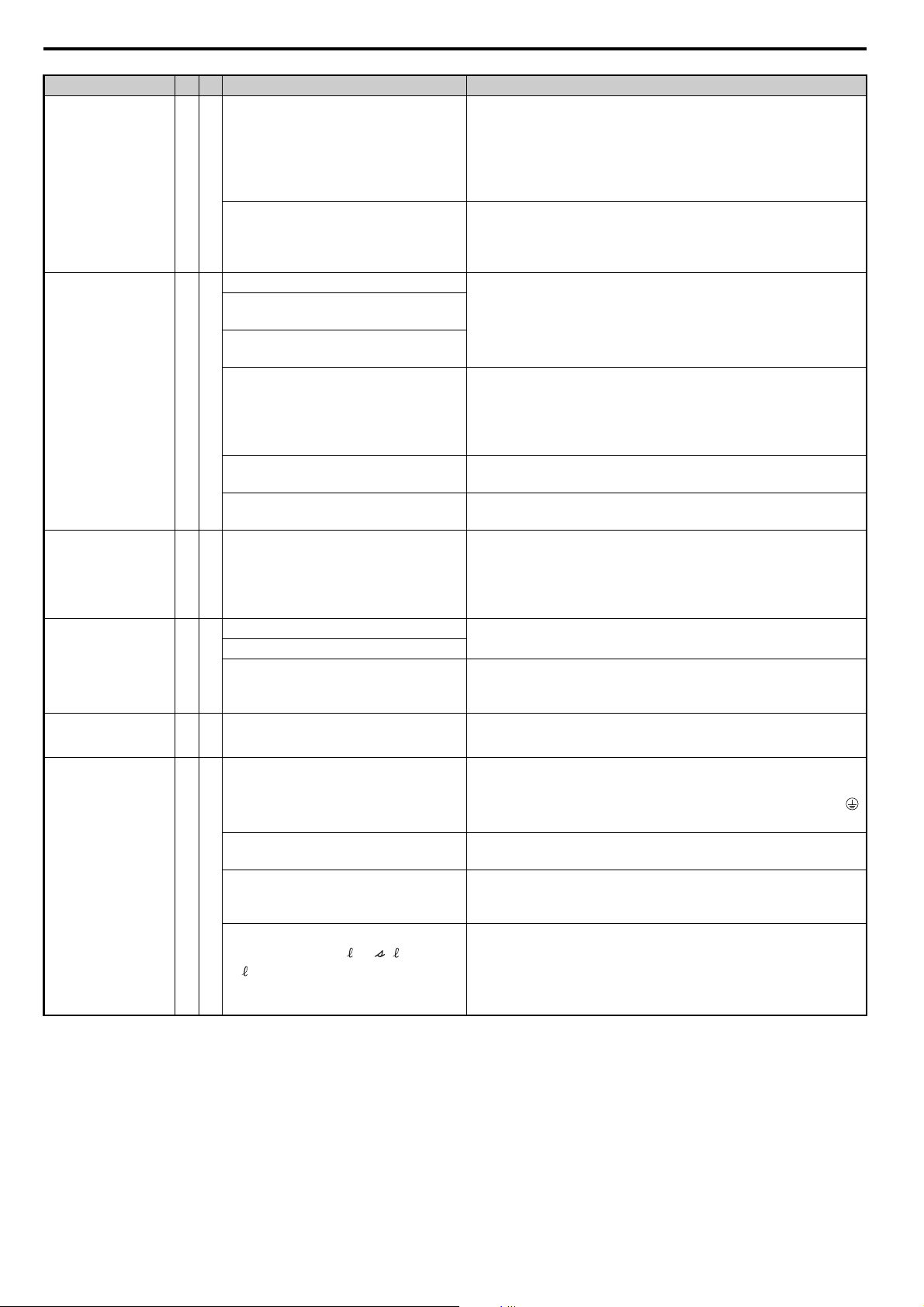
9 Troubleshooting
FAn
FUA
HCA
GF
r1/ 11
1/ 21
t1/ 31
Digital Operator AL FL Cause Corrective Action
• Cycle the power supply and see if the fault occurs again.
• Check the operation of the internal circulation fans.
Converter Internal
Circulation Fan Fault
Power Supply
Frequency Fault
Fdv
AC Fuse Blowout
DC Fuse Blowout
FUd
Current Alarm
Ground Fault
An internal circulation fan is faulty
(2A0130 or 4A0130 to 4A0370).
{{
An internal circulation fan or MC power
supply is faulty (2A0130 or 4A0130 to
4A0370).
A momentary power loss occurred.
An input power supply wiring terminal is
loose.
The fluctuation in the voltage of the input
power supply is too large.
{{
{ Load is too heavy.
The AC power supply fuse burned out.
The phase rotation direction has changed
in the input power supply.
The detected power supply frequency
exceeded the allowable value.
{ The power supply fuse burned out.
The main transistor failed.
The DC circuit fuse burned out.
{
The drive failed.
A damaged cable is creating a short
circuit.
Excessive leakage current at the drive
output.
{
Hardware problem
The wiring of the power supply voltage
detection circuits ( , , and
) and the wiring of the main circuit
terminals (R/L1, S/L2, and T/L3) is not
correct.
• Check U4-03 (Cooling Fan Operation Time) and U4-04 (Cooling
Fan Maintenance Display).
If the life of the internal circulation fans has expired or if a fan is faulty,
perform fan replacement according to instructions in this manual.
Cycle the power supply and see if the fault occurs again.
If the fault occurs repeatedly, replace the board or the converter. For
information on board replacement, consult with your Yaskawa
representative or the nearest Yaskawa sales office.
Investigate and correct the cause and then reset the fault.
• A transistor inside the converter was destroyed.
• The input wiring or drive output has ground faulted or short
circuited.
Contact your Yaskawa representative or the nearest Yaskawa sales
office.
Correct the wiring.
Improve the power supply.
• A transistor inside the converter was destroyed.
• The input wiring or drive output has ground faulted or short
circuited.
Contact your Yaskawa representative or the nearest Yaskawa sales
office.
Replace the converter.
Replace the drive.
For information on drive replacement, consult with your Yaskawa
representative or the nearest Yaskawa sales office.
Reduce the load for applications with repetitive operations (i.e., stops
and starts), or replace the converter.
Check the cable.
• Remove the short circuit and reapply power to the converter.
• Check the resistance between the cable and the ground terminal .
• Replace the cable.
Reduce the amount of stray capacitance.
If the problem continues, replace the control board or the entire
converter. Contact Yaskawa or a Yaskawa representative for
instructions on replacing the control board.
Correct the wiring.
44 YASKAWA ELECTRIC TOEP C710656 06A YASKAWA Power Regenerative Converter - D1000 Quick Start Guide
Page 45

Digital Operator AL FL Cause Corrective Action
oC
r1/ 11
1/ 21
t1/ 31
oFb03 to oFb17
oH
oH1
Check the motor cables.
• Remove the short circuit and reapply power to the converter.
Check the resistance between the motor cables and the ground
terminal .
• Replace damaged cables.
• Reapply power to the converter.
• Measure the current flowing into the converter.
• Replace the converter with a larger capacity converter if the current
value exceeds the rated current.
• Determine if there is sudden fluctuation in the current level.
• Reduce the load to avoid sudden changes in the current level or
switch to a larger converter.
• Review the possible solutions provided for handling noise
interference.
• Check the control circuit lines, main circuit lines, and ground wiring.
Correct the wiring.
Check the wiring.
• Correct the wiring.
Check the load on the power supply of peripheral devices that are
connected to the same power supply line.
• Reduce the load.
Cycle power to the converter.
If the problem continues, replace the control board or the entire
converter. Contact Yaskawa or a Yaskawa representative for
instructions on replacing the control board.
Check the surrounding temperature.
• Improve the air circulation within the enclosure panel.
• Install a fan or air conditioner to cool surrounding area.
• Remove anything near converter that may cause extra heat.
• Provide proper installation space around the converter as indicated in
the manual. Refer to Installation Orientation and Spacing on
page 10 for details.
• Allow for the proper space and ensure that there is sufficient
circulation around the control panel.
• Check for dust or other foreign materials clogging the cooling fan.
• Clear debris caught in the fan that restricts air circulation.
Check the ambient temperature.
• Improve ventilation in the control panel.
• Install a cooling device (e.g., a cooling fan or air conditioner) and
lower the ambient temperature.
• If there are heat-generating objects nearby, remove them.
Measure the output current.
Lower the load.
Replace the cooling fan.
After replacing the converter, set parameter o4-03 to 0 to reset the
cooling fan operation time.
Check the temperature surrounding the converter.
• Improve the air circulation within the enclosure panel.
• Install a fan or air conditioner to cool the surrounding area.
• Remove anything near the converter that might be producing
excessive heat.
Measure the output current.
Reduce the load.
Replace the cooling fan.
After replacing the cooling fan, set parameter o4-03 to 0 to reset the
cooling fan maintenance.
Overcurrent
Option card error
occurred at Option
Port CN5-B
Heatsink Overheat
Overheat 1
(Heatsink Overheat)
One of the cables has shorted out or there
is a grounding problem.
The load is too heavy.
{
Converter fails to operate properly due to
noise interference.
The wiring of the power supply voltage
detection circuits ( , , and
) and the wiring of the main circuit
terminals (R/L1, S/L2, and T/L3) is not
correct.
The voltage on the power supply side is
very low.
{ Option card or hardware is damaged.
Surrounding temperature is too high.
Airflow around the converter is restricted.
{{
The ambient temperature is too high.
The load is too large.
Internal cooling fan has stopped.
rounding temperature is
Sur
{
Load is too heavy.
Internal cooling fan is stopped.
too high.
9 Troubleshooting
YASKAWA ELECTRIC TOEP C710656 06A YASKAWA Power Regenerative Converter - D1000 Quick Start Guide 45
Page 46

9 Troubleshooting
oL2
r1/ 11
1/ 21
t1/ 31
r1/ 11, 1/ 21, and t1/ 31
SC
SrC
Digital Operator AL FL Cause Corrective Action
Converter Overload
External Digital
Operator Connection
Fault
oPr
DC Bus Overvoltage
ov
Power Supply
Undervoltage
Pre-Alarm
PAUv
Input Power Supply
Fault
PF2
Input Phase Loss
Detection
PF3
Input Short-circuit/
Main Transistor
Failure
Phase Order Fault
{{
{{
{
{{
{{
Load is too heavy. Reduce the load.
Converter capacity is too small. Replace the converter with a larger model.
The converter does not operate. Start converter operation first, and then start converter operation.
Check the connection between the operator and the converter.
External operator is not properly
{
connected to the converter.
The regenerative load is too large. Reduce the regenerative load.
Input power voltage is too high.
Converter fails to operate properly due to
noise interference.
The wiring of the power supply voltage
detection circuits ( , , and
) and the wiring of the main circuit
terminals (R/L1, S/L2, and T/L3) is not
correct.
Electrical noise interference causes the
converter to operate incorrectly.
There is a regenerative load while the
converter is stopped.
The power supply voltage is low. Increase the power supply voltage.
A phase loss occurred in the input power
supply.
Voltage detection failed.
The fluctuation in the voltage of the input
power supply is too large.
A phase loss occurred in the input power
supply.
{
The capacity of the power supply is too
small.
The wiring is too long.
The phase imbalance is too large.
The fluctuation in the voltage of the input
power supply is too large.
A phase loss occurred in the input power
supply.
The capacity of the power supply is too
small.
The wiring is too long.
The phase imbalance is too large.
BT fa
IG
{
IGBT short circuit detection circuit fault.
The power supply phase order changed
during operation.
A momentary power loss occurred.
An input power supply wiring terminal is
loose.
The fluctuation in the voltage of the input
power supply is too large.
ult
• Replace the cable if damaged.
• Turn off the input power and disconnect the operator. Reconnect the
operator and reapply converter input power.
Check the voltage.
Lower input power voltage within the limits listed in the
specifications.
• Review the list of possible solutions provided for controlling noise.
• Review the section on handling noise interference and check the
control circuit lines, main circuit lines, and ground wiring.
Correct the wiring.
• Review possible solutions for handling noise interference.
• Review section on handling noise interference and check control
circuit lines, main circuit lines and ground wiring.
• If the magnetic contactor is identified as a source of noise, install a
surge protector to the MC coil.
Set number of fault restarts (L5-01) to a value other than 0.
Operate the converter.
Check the input power supply for phase loss or an imbalance in the
interphase voltages.
Investigate and correct the cause and then reset the fault.
Check to see if they are wired correctly.
Investigate and correct the cause and then reset the fault.
Investigate and correct the cause and then reset the fault.
• Check the wiring to the drive.
• Turn the power supply off and then on again to check operation.
If the problem continues, contact your Yaskawa representative or
nearest Yaskawa sales office.
Investigate and correct the cause and then reset the fault.
46 YASKAWA ELECTRIC TOEP C710656 06A YASKAWA Power Regenerative Converter - D1000 Quick Start Guide
Page 47
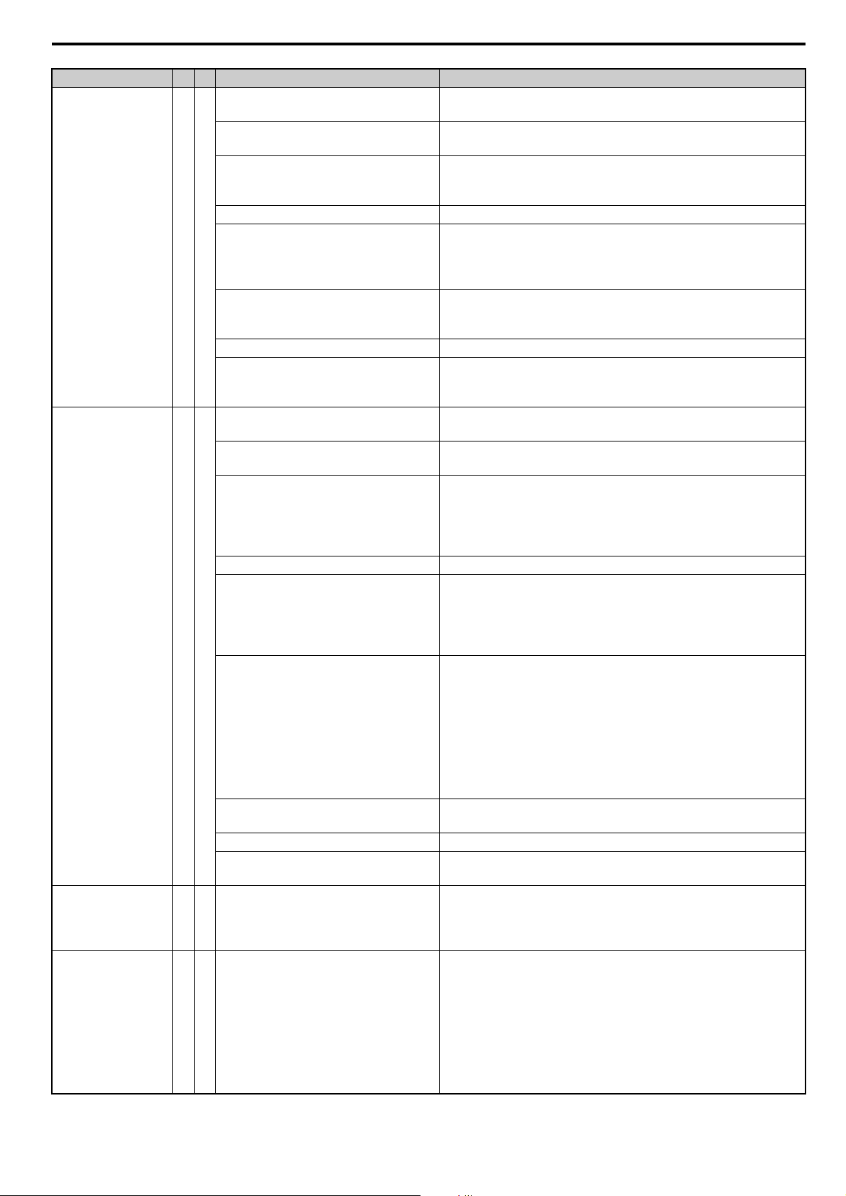
Digital Operator AL FL Cause Corrective Action
Uv
Check for wiring errors in the main circuit input power. Correct the
wiring.
• Ensure the terminals have been properly tightened.
• Apply the tightening torque to the terminals as specified.
• Check the voltage.
• Lower the voltage of the converter input power so that it is within the
limits listed in the specifications.
Check the maintenance time for the capacitors (U4-05). Replace either
the control board or the entire converter if U4-05 exceeds 90%. For
instructions on replacing the control board, contact Yaskawa or your
nearest sales representative.
• Check for an alarm when the magnetic contactor, line breaker, and
leakage breaker are closed.
• Check the capacity of the converter input power transformer.
Replace either the control board or the entire converter. For
instructions on replacing the control board, contact Yaskawa or your
nearest sales representative.
Check the wiring of the main circuit power supply for broken wires
and wiring mistakes. Correct the wiring.
Check the terminals for looseness. Tighten the terminals to the
tightening torque that is given in this manual.
Check the voltage.
• Correct the voltage so that it is within the range given in the power
supply specifications of the converter.
• If there is no problem with the main circuit power supply, check the
magnetic contactor in the main circuit for faults.
Check the maintenance period for the capacitor in U4-05 (Capacitor
Maintenance).
If the value of U4-05 has exceeded 90%, replace the board or the
converter. For information on board replacement, consult with your
Yaskawa representative or the nearest Yaskawa sales office.
Cycle the power supply and see if the fault occurs again.
• If the fault occurs repeatedly, replace the board or the converter. For
information on board replacement, consult with your Yaskawa
representative or the nearest Yaskawa sales office. Check the
maintenance period for the inrush prevention relay in U4-06 (Soft
Charge Bypass Relay Maintenance).
• If the value of U4-06 has exceeded 90%, replace the board or the
converter. For information on board replacement, consult with your
Yaskawa representative or the nearest Yaskawa sales office.
Check the wiring of the power supply device.
Correct the wiring.
Check the
Correct the wiring.
• Cycle power to the converter. Check if the fault reoccurs.
• If the problem continues, replace either the control board or the
entire converter. For instructions on replacing the control board,
contact Yaskawa or a Yaskawa representative.
• Cycle power to the converter and see if the fault reoccurs.
If the problem continues, replace either the control board or the entire
converter. For instructions on replacing the control board, contact
Yaskawa or a Yaskawa representative.
• Check monitor U4-06 for the performance life of the soft-charge
bypass.
Replace either the control board or the entire converter if U4-06
exceeds 90%. For instructions on replacing the control board, contact
Yaskawa or a Yaskawa representative.
wiring.
Undervoltage
Main Circuit
Undervoltage
Uv1
Control Power Supp
Voltage Fault
Uv2
Undervoltage 3
(Soft-Charge Bypass
Circuit Fault)
Uv3
Phase loss in the converter input power.
Loose wiring in the converter input power
terminals.
There is a problem with the converter
input power voltage.
A power loss occurred. Improve the power supply.
{
ly
Internal circuitry is worn.
The converter input power transformer is
too small and voltage drops when the
power is switched on.
Air inside the converter is too hot. Check the temperature inside the converter.
The CHARGE light is broken or
disconnected.
A phase loss occurred in the input power
supply.
An input power supply wiring terminal is
loose.
Fluctuation occurred in the power supply
voltage.
A power loss occurred. Improve the power supply.
The main circuit capacitor circuit in the
converter has deteriorated.
{
The operation of the relay or contactor in
the inrush current protection circuit in the
converter failed.
A fault occurred in the power supply
device.
A fault occurred in the power supply. A fault occurred in the power supply.
A fault occurred in power supply voltage
detection.
{ Internal circuitry is damaged.
The relay or contactor on the soft-charge
{
bypass circuit is damaged.
9 Troubleshooting
YASKAWA ELECTRIC TOEP C710656 06A YASKAWA Power Regenerative Converter - D1000 Quick Start Guide 47
Page 48
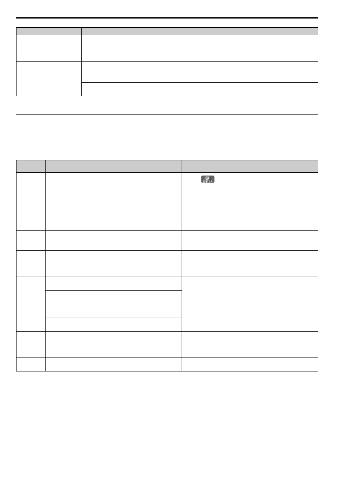
9 Troubleshooting
VrE
Err
oPE01
oPE02
oPE03
oPE04
oPE05
oPE07
oPE30
Digital Operator AL FL Cause Corrective Action
Gate Drive Board
Undervoltage <2>
Uv4
Resonance Detection
<1> If the fault occurs when starting the converter, CPF00 or CPF20 is displayed. If it occurs during operation, CPF01 or CPF21 is displayed.
<2> Detected in model 4A0630
{{
Not enough power is being supplied to the
{
gate drive board.
The power supply was turned off during
operation.
There is noise on the power supply line. Investigate the source of the noise and implement countermeasures.
A phase was lost for an input terminal
during operation.
Cycle power to the converter and see if the fault reoccurs.
If the problem continues, replace either the gate drive board or the
entire converter. For instructions on replacing the gate drive board,
contact Yaskawa or a Yaskawa representative.
Stop the operation of the converter and turn off the power supply.
Check the wiring of the power supply system and remove the cause of
the phase loss.
Operator Programing Errors
An Operator Programming Error (oPE) occurs when an inapplicable parameter is set or an individual parameter setting is
inappropriate. When an oPE error is displayed, press the ENTER button to display U1-18 (oPE fault constant). This
monitor will display the parameter that is causing the oPE error.
Digital
Operator
Cause Corrective Action
The data was corrupted by noise when writing data to the
EEPROM.
EEPROM Hardware Failure
The drive model selection (o2-04) and the actual capacity of the
converter are not the same.
Parameters were set outside the possible setting range.
The same function is assigned to two multi-function inputs.
Excludes “Not used” and “External Fault.”
The converter was replaced (but the removable terminal block
with parameter backup was not replaced).
The removable terminal block with parameter backup was
replaced.
The Run command is assigned to an option card (b1-18 = 3) and
an input option card is not connected to the converter.
The Run command is assigned to an option card (b1-02 = 3) and
an input option card is not connected to the converter.
At least two of these parameters have the same setting: H3-02,
H3-10, or H3-06.
• The setting of o2-04 (Drive Model Selection) changed.
• EEPROM failed for the input voltage offset.
•Press .
• Set the parameters again.
• Cycle the power supply.
Replace the board or converter. For information on board
replacement, consult with your Yaskawa representative or the
nearest Yaskawa sales office.
Correct the value set to o2-04.
Set parameters to the proper values.
Note: When multiple errors occur simultaneously, other errors
are given precedence over oPE02.
• Ensure all multi-function inputs are assigned to different
functions.
• Re-enter the multi-function settings to ensure this does not
occur.
Set A1-03 to 5550 to load the parameter settings stored in the
terminal board to the converter. Initialize parameters after
converter replacement by setting A1-03 to 2220.
Reconnect the input option card to the converter.
Change the settings to H3-02, H3-10, and H3-06 so that
functions no longer conflict.
Note: Both 1F (Through mode) and F (Through mode) can be set
to H3-02, H3-10, or H3-06 simultaneously.
For information on clearing the fault, consult with your Yaskawa
representative or the nearest Yaskawa sales office.
48 YASKAWA ELECTRIC TOEP C710656 06A YASKAWA Power Regenerative Converter - D1000 Quick Start Guide
Page 49

10 UL Standards
10 UL Standards
UL Standards
The RU mark applies to products in the United States and Canada and it means that UL has performed product testing
and evaluation and determined that their stringent standards for product safety have been met. For a product to receive
UL certification, all components inside that product must also receive UL certification.
RU Mark
UL Standards Compliance
This converter is tested in accordance with UL standard UL508C and complies with UL requirements. To ensure
continued compliance when using this converter in combination with other equipment, meet the following conditions:
Installation Area
Do not install the converter to an area greater than pollution severity 2 (UL standard).
Ambient Temperature
IP00 Open Type Enclosure: -10°C to +50°C
IP20 Open Type Enclosure: -10°C to +40°C
Main Circuit Terminal Wiring
Yaskawa recommends using closed-loop crimp terminals on all converter models. To maintain UL/cUL approval,
UL-Listed closed-loop crimp terminals are specifically required when wiring the converter main circuit terminals on
models 2A0030 to 2A0130, 4A0030 to 4A0630. Use only the tools recommended by the terminal manufacturer for
crimping. Refer to Closed-Loop Crimp Terminal Recommendations on page 51 for closed-loop crimp terminal
recommendations. The wire gauges listed in the following tables are Yaskawa recommendations. Refer to local codes for
proper wire gauge selections.
Note: The mark indicates the terminals for protective ground connection as defined in IEC/EN60417-5019.
Grounding impedance:
200 V: 100 Ω or less
400 V: 10 Ω or less
Wire Gauges and Tightening Torques
Table 17 Wire Gauge and Torque Specifications (Three-Phase 200 V Class)
Model Term ina l
R/L1, S/L2, T/L3
2A0005
2A0010
2A0020
,
r1/ 11, 1/ 21, t1/ 31 14 14 M3.5 0.8 to 1.0 (7.1 to 8.9)
R/L1, S/L2, T/L3
,
r1/ 11, 1/ 21, t1/ 31 14 14 M3.5 0.8 to 1.0 (7.1 to 8.9)
R/L1, S/L2, T/L3
,
r1/ 11, 1/ 21, t1/ 31 14 14 M3.5 0.8 to 1.0 (7.1 to 8.9)
Recommended
Gauge
AWG, kcmil
12 12 to 6 M4 2.1 to 2.3 (18.6 to 20.4)
10 16 to 10 M6 5.4 to 6.0 (47.8 to 53.1)
8 8 to 6 M4 2.1 to 2.3 (18.6 to 20.4)
10 12 to 10 M6 5.4 to 6.0 (47.8 to 53.1)
4 4 to 1 M6 3.6 to 4.0 (31.9 to 35.4)
6 8 to 6 M6 5.4 to 6.0 (47.8 to 53.1)
Wire Range
AWG, kcmil
Screw Size
Tightening Torque
Nxm (lbxin.)
YASKAWA ELECTRIC TOEP C710656 06A YASKAWA Power Regenerative Converter - D1000 Quick Start Guide 49
Page 50

10 UL Standards
Model Terminal
R/L1, S/L2, T/L3
2A0030
2A0050
2A0065
2A0090
2A0130
,
r1/ 11, 1/ 21, t1/ 31 14 14 to 10 M4 1.1 to 1.2 (9.7 to 10.6)
R/L1, S/L2, T/L3 3 × 2P 3 to 2/0
,
r1/ 11, 1/ 21, t1/ 31 14 14 to 10 M4 1.1 to 1.2 (9.7 to 10.6)
R/L1, S/L2, T/L3
,
r1/ 11, 1/ 21, t1/ 31 14 14 to 10 M4 1.1 to 1.2 (9.7 to 10.6)
R/L1, S/L2, T/L3
,
r1/ 11, 1/ 21, t1/ 31 14 14 to 10 M4 1.1 to 1.2 (9.7 to 10.6)
R/L1, S/L2, T/L3
,
r1/ 11, 1/ 21, t1/ 31 14 14 to 10 M4 1.1 to 1.2 (9.7 to 10.6)
Recommended
Gauge
AWG, kcmil
2 2 to 2/0 M8 5.4 to 6.0 (47.8 to 53.1)
4 6 to 4 M8 9.0 to 11 (79.7 to 97.4)
1/0 × 2P 1/0 to 2/0
4 4 M10 18 to 23 (159 to 204)
3/0 × 2P 3/0 to 300 M12 32 to 40 (283 to 354)
1 1 to 1/0 M12 32 to 40 (283 to 354)
3/0 × 2P 3/0 to 300 M12 32 to 40 (283 to 354)
1/0 1/0 to 4/0 M12 32 to 40 (283 to 354)
300 × 2P 300 to 600 M12 32 to 40 (283 to 354)
2/0 2/0 to 4/0 M12 32 to 40 (283 to 354)
Wire Range
AWG, kcmil
Screw Size
M8 5.4 to 6.0 (47.8 to 53.1)
Tightening Torque
Nxm (lbxin.)
Table 18 Wire Gauge and Torque Specifications (Three-Phase 400 V Class)
Model Terminal
R/L1, S/L2, T/L3
4A0005
4A0010
4A0020
4A0030
4A0040
4A0060
,
r1/ 11, 1/ 21, t1/ 31 14 14 M3.5 0.8 to 1.0 (7.1 to 8.9)
R/L1, S/L2, T/L3
,
r1/ 11, 1/ 21, t1/ 31 14 14 M3.5 0.8 to 1.0 (7.1 to 8.9)
R/L1, S/L2, T/L3
,
r1/ 11, 1/ 21, t1/ 31 14 14 M3.5 0.8 to 1.0 (7.1 to 8.9)
R/L1, S/L2, T/L3
,
r1/ 11, 1/ 21, t1/ 31 14 14 to 10 M4 1.1 to 1.2 (9.7 to 10.6)
R/L1, S/L2, T/L3
,
r1/ 11, 1/ 21, t1/ 31 14 14 to 10 M4 1.1 to 1.2 (9.7 to 10.6)
R/L1, S/L2, T/L3
,
r1/ 11, 1/ 21, t1/ 31 14 14 to 10 M4 1.1 to 1.2 (9.7 to 10.6)
Recommended
Gauge
AWG, kcmil
12 12 to 6 M4 2.1 to 2.3 (18.6 to 20.4)
12 14 to 12 M6 5.4 to 6.0 (47.8 to 53.1)
12 12 to 6 M4 2.1 to 2.3 (18.6 to 20.4)
10 12 to 10 M6 5.4 to 6.0 (47.8 to 53.1)
8 8 to 1 M6 3.6 to 4.0 (31.9 to 35.4)
8 10 to 8 M6 5.4 to 6.0 (47.8 to 53.1)
6 6 to 2/0 M8 5.4 to 6.0 (47.8 to 53.1)
6 8 to 6 M8 9.0 to 11 (79.7 to 97.4)
4 4 to 2/0 M8 5.4 to 6.0 (47.8 to 53.1)
6 6 M8 9.0 to 11 (79.7 to 97.4)
2 2 to 2/0 M8 5.4 to 6.0 (47.8 to 53.1)
6 6 M10 18 to 23 (159 to 204)
Wire Range
AWG, kcmil
Screw Size
Tightening Torque
Nxm (lbxin.)
50 YASKAWA ELECTRIC TOEP C710656 06A YASKAWA Power Regenerative Converter - D1000 Quick Start Guide
Page 51

10 UL Standards
Model Term ina l
R/L1, S/L2, T/L3 3 × 2P 3 to 2/0
4A0100
4A0130
4A0185
4A0270
4A0370
4A0630
,
r1/ 11, 1/ 21, t1/ 31 14 14 to 10 M4 1.1 to 1.2 (9.7 to 10.6)
R/L1, S/L2, T/L3
,
r1/ 11, 1/ 21, t1/ 31 14 14 to 10 M4 1.1 to 1.2 (9.7 to 10.6)
R/L1, S/L2, T/L3
,
r1/ 11, 1/ 21, t1/ 31 14 14 to 10 M4 1.1 to 1.2 (9.7 to 10.6)
R/L1, S/L2, T/L3
,
r1/ 11, 1/ 21, t1/ 31 14 14 to 10 M4 1.1 to 1.2 (9.7 to 10.6)
R/L1, S/L2, T/L3
,
r1/ 11, 1/ 21, t1/ 31 14 14 to 10 M4 1.1 to 1.2 (9.7 to 10.6)
R/L1, S/L2, T/L3
,
r1/ 11, 1/ 21, t1/ 31 14 14 to 10 M4 1.1 to 1.2 (9.7 to 10.6)
Recommended
Gauge
AWG, kcmil
1/0 × 2P 1/0 to 2/0
3 3 M10 18 to 23 (159 to 204)
3/0 × 2P 3/0 to 600 M10 18 to 23 (159 to 204)
1/0 1/0 to 2/0 M10 18 to 23 (159 to 204)
3/0 × 2P 3/0 to 600 M12 32 to 40 (283 to 354)
1/0 1/0 to 4/0 M12 32 to 40 (283 to 354)
300 × 2P 300 M12 32 to 40 (283 to 354)
2/0 2/0 to 4/0 M12 32 to 40 (283 to 354)
4/0 × 4P 4/0 to 300 M12 32 to 40 (283 to 354)
4/0 2/0 to 300 M12 32 to 40 (283 to 354)
4/0 × 8P 4/0 to 300 M12 32 to 40 (283 to 354)
250 2/0 to 300 M12 32 to 40 (283 to 354)
Wire Range
AWG, kcmil
Screw Size
M8 5.4 to 6.0 (47.8 to 53.1)
Tightening Torque
Nxm (lbxin.)
Closed-Loop Crimp Terminal Recommendations
Yaskawa recommends UL-listed crimp terminals made by JST and Tokyo DIP (or equivalent) for the insulation cap.
Tab le 1 9 matches the wire gauges and terminal screw sizes with Yaskawa-recommended crimp terminals, tools, and
insulation caps. Refer to the appropriate Wire Gauge and Torque Specifications table for the wire gauge and screw size
for your converter model. Place orders with a Yaskawa representative or the Yaskawa sales department. The closed-loop
crimp terminal sizes and values listed in Table 19 are Yaskawa recommendations. Wire gauge values shown in Ta bl e 1 9
are the recommended values. Refer to local codes for proper selections.
Table 19 Closed-Loop Crimp Terminal Size
Model
2A0005
2A0010
2A0020
2A0030
Wire Gauge (AWG, kcmil)
R/L1xS/L2xT/L3 U/T1xV/T2xW/T3
12
10 R5.5-4 YA-4 AD-900 TP-005 100-054-029
8 8-4 YA-4 AD-901 TP-008 100-054-031
6 14-NK4 YA-4 AD-902 TP-014 100-054-033
8
6 14-NK4 YA-4 AD-902 TP-014 100-054-033
4
3 38-6 YA-5 AD-954 TP-038 100-092-577
2 38-6 YA-5 AD-954 TP-038 100-092-577
1 60-6 YA-5 AD-955 TP-060 100-092-578
2
1 R60-8 YA-5 AD-955 TP-060 100-051-265
1/0 R60-8 YA-5 AD-955 TP-060 100-051-265
2/0 80-8
Screw
Size
M4
M4
M6
M8
Crimp
Termi nal
Model
Number
200 V Class
R5.5-4 YA-4 AD-900 TP-005 100-054-029
8-4 YA-4 AD-901 TP-008 100-054-031
R22-6 YA-5 AD-953 TP-022 100-051-262
R38-8 YA-5 AD-954 TP-038 100-051-264
Machine
YET-300-1
No.
YF-1,
Tool
Die Jaw
TD-323
TD-312
Insulation
Cap
Model No.
TP-080 100-092-579
Code <1>
YASKAWA ELECTRIC TOEP C710656 06A YASKAWA Power Regenerative Converter - D1000 Quick Start Guide 51
Page 52

10 UL Standards
Model
2A0050
2A0065
2A0090
4A0005
4A0010
4A0020
4A0030
4A0040
Wire Gauge (AWG, kcmil)
R/L1xS/L2xT/L3 U/T1xV/T2xW/T3
3 × 2P –
2 × 2P – R38-8 YA-5 AD-954 TP-038 100-051-264
1 × 2P – R60-8 YA-5 AD-955 TP-060 100-051-265
1/0 × 2P 1/0 × 2P R60-8 YA-5 AD-955 TP-060 100-051-265
2/0 × 2P 2/0 × 2P 80-8
3/0 × 2P
4/0 × 2P 100-L12
250 150-L12
300 150-L12
3/0 × 2P
4/0 × 2P 100-L12
250 × 2P 150-L12
300 × 2P 150-L12
12
10 R5.5-4 YA-4 AD-900 TP-005 100-054-029
8 8-4 YA-4 AD-901 TP-008 100-054-031
6 14-NK4 YA-4 AD-902 TP-014 100-054-033
12
10 R5.5-4 YA-4 AD-900 TP-005 100-054-029
8 8-4 YA-4 AD-901 TP-008 100-054-031
6 14-NK4 YA-4 AD-902 TP-014 100-054-033
8
6 R14-6 YA-4 AD-902 TP-014 100-051-261
4 R22-6 YA-5 AD-953 TP-022 100-051-262
3 38-6 YA-5 AD-954 TP-038 100-092-577
2 38-6 YA-5 AD-954 TP-038 100-092-577
1 60-6 YA-5 AD-955 TP-060 100-092-578
6
4 R22-8 YA-5 AD-953 TP-022 100-051-263
3 R38-8 YA-5 AD-954 TP-038 100-051-264
2 R38-8 YA-5 AD-954 TP-038 100-051-264
1 R60-8 YA-5 AD-955 TP-060 100-051-265
1/0 R60-8 YA-5 AD-955 TP-060 100-051-265
2/0 80-8
4
3 R38-8 YA-5 AD-954 TP-038 100-051-264
2 R38-8 YA-5 AD-954 TP-038 100-051-264
1 R60-8 YA-5 AD-955 TP-060 100-051-265
1/0 R60-8 YA-5 AD-955 TP-060 100-051-265
2/0 80-8
Screw
Size
M8
M12
M12
M4
M4
M6
M8
M8
Crimp
Terminal
Model
Number
R38-8 YA-5 AD-954 TP-038 100-051-264
80-L12
80-L12
400 V Class
R5.5-4 YA-4 AD-900 TP-005 100-054-029
R5.5-4 YA-4 AD-900 TP-005 100-054-029
R8-6 YA-4 AD-901 TP-008 100-092-620
R14-8 YA-4 AD-902 TP-014 100-051-035
R22-8 YA-5 AD-953 TP-022 100-051-263
Machine
YET-300-1
YET-300-1
YET-300-1
YET-300-1
YET-300-1
YET-300-1
YET-300-1
YET-300-1
YET-300-1
YET-300-1
YET-300-1
No.
YF-1,
YF-1,
YF-1,
YF-1,
YF-1,
YF-1,
YF-1,
YF-1,
YF-1,
YF-1,
YF-1,
Tool
Die Jaw
TD-323,
TD-312
TD-323,
TD-312
TD-324,
TD-312
TD-325,
TD-313
TD-325,
TD-313
TD-323,
TD-312
TD-324,
TD-312
TD-325,
TD-313
TD-325,
TD-313
TD-323,
TD-312
TD-323,
TD-312
Insulation
Cap
Model No.
TP-080 100-092-579
TP-080 100-051-558
TP-100 100-051-560
TP-150 100-051-562
TP-150 100-051-562
TP-080 100-051-558
TP-100 100-051-560
TP-150 100-051-562
TP-150 100-051-562
TP-080 100-092-579
TP-080 100-092-579
Code <1>
52 YASKAWA ELECTRIC TOEP C710656 06A YASKAWA Power Regenerative Converter - D1000 Quick Start Guide
Page 53

10 UL Standards
Wire Gauge (AWG, kcmil)
Model
4A0060
4A0100
4A0130
4A0185
4A0270 300 × 2P M12 150-L12
4A0370
4A0630
R/L1xS/L2xT/L3 U/T1xV/T2xW/T3
2
1 R60-8 YA-5 AD-955 TP-060 100-051-265
1/0 R60-8 YA-5 AD-955 TP-060 100-051-265
2/0 80-8
3 × 2P –
2 × 2P – R38-8 YA-5 AD-954 TP-038 100-051-264
1 × 2P – R60-8 YA-5 AD-955 TP-060 100-051-265
1/0 × 2P R60-8 YA-5 AD-955 TP-060 100-051-265
2/0 × 2P 80-8
3/0 × 2P
4/0 × 2P 100-L10
250 × 2P 250 150-L10
300 R150-10
350 200-10
400 200-10
500 325-10
600 325-10
3/0 × 2P
4/0 × 2P 100-L12
250 × 2P 150-L12
300 × 2P 150-L12
350 × 2P 200-L12
400 × 2P 200-L12
500 325-12
600 325-12
4/0 × 4P
250 × 4P 150-L12
300 × 4P 150-L12
4/0 × 8P
250 × 8P 150-L12
300 × 8P 150-L12
Screw
Size
M8
M8
M10
M12
M12
M12
Crimp
Termi nal
Model
Number
R38-8 YA-5 AD-954 TP-038 100-051-264
R38-8 YA-5 AD-954 TP-038 100-051-264
80-L10
80-L12
100-L12
100-L12
Machine
No.
YF-1,
YET-300-1
YF-1,
YET-300-1
YF-1,
YET-300-1
YF-1,
YET-300-1
YF-1,
YET-300-1
YF-1,
YET-300-1
YF-1,
YET-300-1
YF-1,
YET-300-1
YF-1,
YET-300-1
YF-1,
YET-300-1
YF-1,
YET-300-1
YF-1,
YET-300-1
YF-1,
YET-300-1
YF-1,
YET-300-1
YF-1,
YET-300-1
YF-1,
YET-300-1
YF-1,
YET-300-1
YF-1,
YET-300-1
YF-1,
YET-300-1
YF-1,
YET-300-1
YF-1,
YET-300-1
YF-1,
YET-300-1
YF-1,
YET-300-1
YF-1,
YET-300-1
YF-1,
YET-300-1
Tool
Die Jaw
TD-323,
TD-312
TD-323,
TD-312
TD-323,
TD-312
TD-324,
TD-312
TD-325,
TD-313
TD-325,
TD-313
TD-327,
TD-314
TD-327,
TD-314
TD-328,
TD-315
TD-328,
TD-315
TD-323,
TD-312
TD-324,
TD-312
TD-325,
TD-313
TD-325,
TD-313
TD-327,
TD-314
TD-327,
TD-314
TD-328,
TD-315
TD-328,
TD-315
TD-325,
TD-313
TD-324,
TD-312
TD-325,
TD-313
TD-325,
TD-313
TD-324,
TD-312
TD-325,
TD-313
TD-325,
TD-313
Insulation
Cap
Model No.
TP-080 100-092-579
TP-080 100-092-579
TP-080 100-051-557
TP-100 100-051-559
TP-150 100-051-561
TP-150 100-051-272
TP-200 100-051-563
TP-200 100-051-563
TP-325 100-051-565
TP-325 100-051-565
TP-080 100-051-557
TP-100 100-051-559
TP-150 100-051-561
TP-150 100-051-561
TP-200 100-051-564
TP-200 100-051-564
TP-325 100-051-277
TP-325 100-051-277
TP-150 100-051-561
TP-100 100-051-559
TP-150 100-051-561
TP-150 100-051-561
TP-100 100-051-559
TP-150 100-051-561
TP-150 100-051-561
Code <1>
YASKAWA ELECTRIC TOEP C710656 06A YASKAWA Power Regenerative Converter - D1000 Quick Start Guide 53
Page 54

10 UL Standards
<1> Codes refer to a set of three crimp terminals and three insulation caps. Prepare input and output wiring using two sets for each connection.
Example 1: Models with 300 kcmil for both input and output require one set for input terminals and one set for output terminals, so the user
should order two sets of [100-051-561].
Example 2: Models with 4/0 AWG × 4P for both input and output require four sets for input terminals and four sets for output terminals, so the
user should order eight sets of [100-051-559].
Note: Use crimp insulated terminals or insulated shrink tubing for wiring connections. Wires should have a continuous maximum
allowable temperature of 75°C 600 Vac UL-approved vinyl-sheathed insulation.
Model
2A0005 to 2A0020,
4A0005 to 4A0020
2A0030 to 2A0130,
4A0030 to 4A0630
Wire Gauge (AWG, kcmil)
r1/ 11, 1/ 21, t1/ 31
14 M3.5 R2-3.5 YA-4 AD-900 TP-003 100-106-516
14 M4 R2-4 YA-4 AD-900 TP-003 100-106-517
Screw
Size
Crimp
Ter min al
Model
Number
Machine
No.
Tool
Die Jaw
Insulation
Cap
Model No.
Code
Installing Input Fuses
NOTICE: If a fuse is blown or a Residual Current Device (RCD) is tripped, check the wiring and the selection of the peripheral devices.
Check the wiring and the selection of peripheral devices to identify the cause. Contact Yaskawa before restarting the converter or the
peripheral devices if the cause cannot be identified.
Recommended Branch Circuit Protection
Yaskawa recommends installing an appropriate harmonic filter that has built-in input fuses to maintain compliance with
UL508C.
The fuses are listed in Tab le 9 .
Low Voltage Wiring for Control Circuit Terminals
Wire low voltage wires with NEC Class 1 circuit conductors. Refer to national state or local codes for wiring. The
external power supply shall be a UL listed Class 2 power supply source or equivalent only.
Table 20 Control Circuit Terminal Power Supply
Input/Output Terminal Signal Power Supply Specifications
Multi-function digital inputs
Multi function analog inputs +V, –V, A1, A2, A3, AC
S1, S2, S3, S4, S5, S6, S7, S8,
SC, SN, SP
Use the internal LVLC power supply of the converter. Use class 2 for
external power supply.
Converter Short-Circuit Rating
This converter is suitable for use on a circuit capable of delivering not more than 100,000 RMS symmetrical amperes,
240 Vac for 200 V class converters and 480 Vac for 400 V class converters, when protected by fuses as specified on the
Tab le 9 .
Precautionary Notes on External Heatsink (IP00 Open Type Enclosure)
When using an external heatsink, UL compliance requires that exposed capacitors in the main circuit are covered to
prevent injury to surrounding personnel.
The portion of the external heatsink that projects out can either be protected with the enclosure, or with the appropriate
capacitor cover after converter installation is complete. Use the table below to match converter models and capacitor
cover. Capacitor covers can be ordered from a Yaskawa representative or directly from the Yaskawa sales department.
The table below lists available capacitor covers.
54 YASKAWA ELECTRIC TOEP C710656 06A YASKAWA Power Regenerative Converter - D1000 Quick Start Guide
Page 55

Model Code Number Figure
2A0030
2A0050 100-061-275
2A0065 100-061-277
2A0090 100-061-277
2A0130 100-061-278
4A0030 100-061-274
4A0040 100-061-274
4A0060 100-061-275
4A0100 100-061-275
4A0130 100-061-278
4A0185 100-061-278
4A0270 100-061-280
4A0370 100-061-280
4A0630 100-061-281 <1> Figure 22
<1> Requires two sets.
Figure 19
10 UL Standards
Table 21 Capacitor Cover
100-061-274
Figure 21
Converter (outside panel)
Figure 20
Opening to capacitors
Converter (inside panel)
Capacitor cover
Installation screw
Figure 21 Capacitor Cover (2A0030 to 2A0130, 4A0030 to 4A0370)
Opening to capacitors
Converter (inside panel)
Capacitor cover
Installation screw
Converter (outside panel)
Figure 22 Capacitor Cover (4A0630)
YASKAWA ELECTRIC TOEP C710656 06A YASKAWA Power Regenerative Converter - D1000 Quick Start Guide 55
Page 56

Revision History
The revision dates and the numbers of the revised manuals appear on the bottom of the back cover.
MANUAL NO.ޓTOEP C710656 06A
Published in Japan September 2013 13-9
Date of publication
Date of
Publication
September 2013 −−First edition
Revision Number Section Revised Content
Date of original publication
56 YASKAWA ELECTRIC TOEP C710656 06A YASKAWA Power Regenerative Converter - D1000 Quick Start Guide
Page 57

YASKAWA D1000 Series
Power Regenerative Converter
Quick Start Guide
EUROPEAN HEADQUARTERS
YASKAWA EUROPE GmbH
Hauptstrasse 185, 65760 Eschborn, Germany
Phone: +49 (0)6196 569 300 Fax: +49 (0)6196 569 398
E-mail: info@yaskawa.eu.com Internet: http://www.yaskawa.eu.com
YASKAWA ENGINEERING EUROPE GmbH
Hauptstrasse 185, 65760 Eschborn, Germany
Phone: +49 (0)6196 569 520 Fax: +49 (0)6196 888 598
E-mail: support@yaskawa.de Internet: http://www.yaskawa-eng.eu.com
U.S.A.
YASKAWA AMERICA, INC.
2121 Norman Drive South, Waukegan, IL 60085, U.S.A.
Phone: +1 800 YASKAWA (927-5292) or +1 847 887 7000 Fax: +1 847 887 7310
Internet: http://www.yaskawa.com
JAPAN
YASKAWA ELECTRIC CORPORATION
New Pier Takeshiba South Tower, 1-16-1, Kaigan, Minatoku, Tokyo, 105-6891, Japan
Phone: +81 (0)3 5402 4502 Fax: +81 (0)3 5402 4580
Internet: http://www.yaskawa.co.jp
DRIVE CENTER (INVERTER PLANT)
2-13-1, Nishimiyaichi, Yukuhashi, Fukuoka, 824-8511, Japan
Phone: +81 (0)930 25 3844 Fax: +81 (0)930 25 4369
Internet: http://www.yaskawa.co.jp
YASKAWA ELECTRIC CORPORATION
In the event that the end user of this product is to be the military and said product is to be employed in any weapons systems or the manufacture
thereof, the export will fall under the relevant regulations as stipulated in the Foreign Exchange and Foreign Trade Regulations. Therefore, be sure
to follow all procedures and submit all relevant documentation according to any and all rules, regulations and laws that may apply.
Specifications are subject to change without notice for ongoing product modifications and improvements.
© 2013 YASKAWA ELECTRIC CORPORATION. All rights reserved.
MANUAL NO. TOEP C710656 06A
Published in Japan September 2013 13-9
13-7-6_YEU
 Loading...