

YASKAWA CIMR-ACA2022, CIMR-ACA45P5, CIMR-ACA Series, CIMR-ACA2045, CIMR-ACA4022 Instruction Manual
...Page 1

YASKAWA
Varispeed AC
INSTRUCTION MANUAL
Matrix Converter for Environmentally Friendly Motor Drives
Model: CIMR-ACA
200V Class 5.5 to 45kW ( 9 to 63kVA)
400V Class 5.5 to 75kW (10 to 114kVA)
Upon receipt of the product and prior to initial operation, read these instructions
thoroughly, and retain for future reference.
YASKAWA
MANUAL NO. TOEP C710636 00D
Page 2

Copyright © 2005 YASKAWA ELECTRIC CORPORATION
All rights reserved. No part of this publication may be reproduced, stored in a retrieval system,
or transmitted, in any form, or by any means, mechanical, electronic, photocopying, recording,
or otherwise, without the prior written permission of Yaskawa. No patent liability is assumed
with respect to the use of the information contained herein. Moreover, because Yaskawa is constantly striving to improve its high-quality products, the information contained in this manual is
subject to change without notice. Every precaution has been taken in the preparation of this
manual. Nevertheless, Yaskawa assumes no responsibility for errors or omissions. Neither is
any liability assumed for damages resulting from the use of the information contained in this
publication.
Page 3

Preface
This manual is designed to ensure correct and suitable
application of the Varispeed AC-Series Matrix Converter (referred to as the “MxC”). Read this manual
before attempting to install, operate, maintain, or
inspect the MxC. This manual should be kept in a safe,
convenient location for future reference. Be sure to
have a thorough understanding of all precautions and
safety information before attempting to use this product.
General Precautions
• The diagrams and illustrations in this manual may appear without the covers or safety shields that
are normally affixed to the actual product. This is to provide the user with a better idea of how
the interior of the MxC is designed. Be sure to restore all covers or shields before operating the
MxC, and to follow the instructions described in this manual once the application is running.
• Any illustrations, photographs, or examples used in this manual are provided as examples only.
Some illustrations may not apply to certain MxC models.
• The products and specifications described in this manual or the content and presentation of the
material may be changed without notice to improve the product and/or the manual.
• To order a new copy of this manual, contact your Yaskawa representatives or the nearest
Yaskawa sales office and provide the manual number shown on the front cover.
• If nameplates become warn or damaged, order new ones from your Yaskawa representatives or
the nearest Yaskawa sales office.
i
Page 4

Safety Information
IMPORTANT
WARNING
CAUTION
The symbols below appear throughout this manual to provide precautions and warnings. Failure
to heed the precautions listed in these pages can result in damage to the product or other
devices, even serious or fatal injury.
“WARNING” indicates a safety concern that if not heeded, could possibly result in serious injury
or loss of life.
“CAUTION” indicates that if the information is not heeded, could result in relatively serious or
minor injury, damage to the product, or faulty operation.
Failure to follow information listed as CAUTION can result in serious consequences.
Indicates important information that the user must be aware of while operating the MxC.
ii
Page 5

Safety Precautions
CAUTION
CAUTION
WARNING
Confirmations upon Delivery
• Never install an MxC that is damaged or has missing components.
Failure to do so may result in injury.
Installation
• Always hold the case when carrying the MxC.
If the MxC is held by the front cover, the main body of the MxC may fall, possibly resulting in injury.
• Attach the MxC to a noncombustible material, such as a metallic surface.
Attaching the MxC to combustible material may cause a fire.
• Install a cooling fan or other cooling device when installing more than one MxC in the same enclosure so that the temperature of the air entering the MxCs is below 45°C.
Fire or other damage may result if the MxC overheats.
Wiring
• Always turn off the input power supply before wiring terminals.
• Wiring must be performed by an authorized person qualified in electrical work.
• Be sure that the ground terminal is properly grounded.
• Always check emergency stop circuits after they are wired.
• Never touch the output terminals directly with your hands or allow the output lines to come into con-
• Before turning the power on, make sure that the power LED is off. If the unit is switched on while
• If the MxC is set up for a 3-wire sequence, then be sure that the multi-function input terminals have
Failure to do so may result in electric shock or fire.
Electric shock or fire may result if an untrained individual attempts to wire the MxC.
200 V class: Ground to 100 Ω or less 400 V class: Ground to 10 Ω or less
Failure to do so may result in electric shock or fire.
Failure to verify that all emergency stops are working properly may result in serious injury. The user is responsible for
properly wiring the product.
tact with the MxC case. Never short the output circuits.
Failure to do so may result in a ground short or electric shock.
the power LED is lit, the motor will start automatically.
Failure to check the power LED may result in injury.
been set properly before wiring the control circuit.
Failure to do so will cause the motor to rotate unexpectedly, and may result in damage or personal injury.
iii
Page 6

CAUTION
• Be sure that the ground terminal is properly grounded using a wire of the recommended size.
CAUTION
WARNING
200 V class: Ground to 100 Ω or less 400 V class: Ground to 10 Ω or less
If a wire smaller than the recommended size is used, the MxC may not operate properly.
• Check to be sure that the voltage of the main AC power supply satisfies the rated voltage of the
MxC.
Injury or fire may occur if the voltage is not correct.
• Do not perform voltage tolerance tests on the MxC.
Such tests may damage semiconductor components and other devices.
• Tighten all terminal screws to the specified tightening torque.
Failure to do so may result in fire.
• Do not connect AC power to output terminals U, V, and W.
Circuitry in the MxC will be damaged if voltage is applied to the output terminals.
• Do not wire AC power lines to terminals p1, n1, r2, s2, or t2. These terminals are used for connecting peripheral devices only.
Applying voltage to these terminals will damage the MxC.
• Do not connect phase-advancing capacitors or LC/RC noise filters to the output circuits.
The MxC may be damaged and circuitry may overheat if these devices are connected.
• Do not connect electromagnetic switches or magnetic contactors to the output circuits.
If a load is connected while the MxC is operating, a power surge will trigger the overcurrent protection circuit in the MxC.
Setting Parameters
• Disconnect the load (machine, device) from the motor before performing Rotational Auto-Tuning.
The motor may turn, possibly resulting in injury or damage to equipment. Also, motor constants cannot be correctly set
with the motor attached to a load.
• Stay clear of the motor during Rotational Auto-Tuning.
The motor may start operating suddenly when stopped, possibly resulting in injury.
Te st R un
• Make sure that the front cover is properly attached before turning on the power supply.
Failure to do so may result in electric shock.
• Leave a reasonable amount of space between yourself and the application when using the fault
reset function. The machine may start moving suddenly once the alarm is cleared.
The application should be designed to ensure safety when the MxC is restarted.
Failure to do so may result in injury.
• Provide a separate emergency stop switch (the STOP key on the digital operator works only when
it has been enabled).
Failure to do so may result in injury.
• Reset alarms only after confirming that the RUN signal has been switched off.
Failure to do so may result in injury.
iv
Page 7

CAUTION
• Do not touch the cooling fins (heatsink), braking resistor, or Braking Resistor Unit. These compo-
WARNING
CAUTION
nents can become extremely hot.
These components become hot enough to cause serious burns.
• Be sure that the motor and machine is within the applicable ranges before starting operation.
Failure to do so may result in injury.
• Provide a separate holding brake if necessary.
The external sequence should be designed to ensure that the holding brake is activated in the
event of an emergency, power failure, or fault in the MxC.
Failure to do so may result in injury.
• If using an MxC with an elevator, take proper steps to ensure safety and to prevent the elevator
from falling suddenly.
Failure to observe to do so may result in injury.
• Refrain from checking relay signals while the MxC is running.
Failure to do so may result in damage to the application.
• Be careful when changing any settings in the MxC. The default settings when the MxC is first
shipped are generally set to optimal values.
Failure to do so may result in damage to the application.
Maintenance and Inspection
• Do not touch the MxC terminals. Some of the terminals carry high voltages and are extremely dangerous.
Failure to do so may result in electric shock.
• Always have the protective cover in place when power is being supplied to the MxC. When attaching the cover, always turn off power to the MxC through the MCCB.
Failure to do so may result in electric shock.
• After turning the main circuit power supply off, wait until the CHARGE display light goes out before
performing maintenance or inspections.
The capacitor will remain charged and is dangerous.
• Maintenance, inspection, and replacement of parts must be performed authorized personnel only.
Remove all metal objects, such as watches and rings, before starting work. Always use grounded tools.
Failure to heed these warning may result in electric shock.
• Customers must provide the holding brakes.
Before making any adjustments other than those done in actual operations, be sure to tighten the holding brakes by using
an external sequence.
Failure to do so may result in electric shock.
• If the MxC is used with an elevator, be sure to take safety measures to prevent the car from falling.
Failure to do so may result in electric shock.
• A CMOS IC is used in the control board. Handle the control board and CMOS IC carefully.
The CMOS IC may be destroyed by static electricity if touched directly.
• Do not change any wiring and refrain from removing connectors or the digital operator while the
MxC is operating.
Failure to do so may result in injury.
v
Page 8

Other
WARNING
CAUTION
• Do not attempt to modify or alter the MxC.
Failure to do so may result in injury or electric shock.
• Contact your Yaskawa representative if you intend to use the MxC with a non-Yaskawa motor or
any other motor not listed in Yaskawa product literature.
The MxC can be used with three-phase induction motors with 2, 4, or 6 poles. A multi-pole motor with 8 poles or more, a
PM motor, or a motor designed for use with machine tools cannot be used with the MxC.
• Install adequate branch circuit short circuit protection per applicable codes.
Failure to comply may result in damage to the MxC.
The MxC is suitable for circuits capable of delivering not more than 100,000 RMS symmetrical Amperes, 220 Vac maximum (200 V Class) and 480 Vac maximum (400 V Class).
• If disinfectants or insecticides must be used to treat packing materials such as wooden frames, pallets, or plywood, the packing materials must be treated before the product is packaged, and methods other than fumigation must be used.
Example: Heat treatment, where materials are kiln-dried to a core temperature of 56
minutes or more.
If the electronic products, which include stand-alone products and products installed in machines, are packed with fumigated wooden materials, the electrical components may be greatly damaged by the gases or fumes resulting from the fumigation process. In particular, disinfectants containing halogen, which includes chlorine, fluorine, bromine, or iodine can
contribute to the erosion of the capacitors.
°C for 30
vi
Page 9

Location of Warning Information
Warning
information
position
Illustration shows a CIMR-ACA4011
!
WARNING
Risk of electric shock.
yRead manual before installing.
yWait 5 minutes for capacitor discharge
after disconnecting power supply.
!
AVERTISSEMENT
Risque de décharge électrique.
yLire le manuel avant l' installation.
yAttendre 5 minutes aprés la coupure de
l' allmentation. Pour permettre la
décharge des condensateurs.
y
y
!
Warning information is printed on the MxC as indicated in the following illustration. Obey all
warnings to prevent damage and injury.
Warning Information
Read this manual before installing the MxC.
vii
Page 10

Warranty Information
Free Warranty Period and Scope
Warranty Period
This product is warranted for twelve months after delivery to the customer, or if applicable,
eighteen months from the date of shipment from the Yaskawa factory, whichever comes first.
Scope of Warranty
Inspections
Periodic inspections must be conducted by the customer. However, upon request, someone from
Yaskawa or one of Yaskawa’s Service Centers can inspect the product for a fee. In this case, if
after conferring with the customer, a Yaskawa product is found to be defective due to Yaskawa
workmanship or materials and the defect occurs during the warranty period, then this fee will be
waived and the problem remedied free of charge.
Repairs
If a Yaskawa product is found to be defective due to Yaskawa workmanship or materials and the
defect occurs during the warranty period, Yaskawa will provide a replacement, repair the defective product, and provide shipping to and from the site free of charge.
However, if the Yaskawa Authorized Service Center determines that the problem with a
Yaskawa product is not due to defects in Yaskawa’s workmanship or materials, then the customer will be responsible for the cost of any necessary repairs. Some problems that fall outside
the scope of this warranty are:
• Problems due to improper maintenance or handling, carelessness, or other reasons where the
customer is deemed responsible.
• Problems that result from any additions or modifications made to a Yaskawa product without
having consulted Yaskawa first.
• Problems due to the use of a Yaskawa product outside the operation conditions specified in
the manual.
• Problems caused by natural disaster or fire.
• Any other problems not due to defects in Yaskawa workmanship or materials.
Warranty service is only applicable in Japan.
However, after-sales service is available for customers outside of Japan for a reasonable fee.
Contact your local Yaskawa representative for more information.
Exceptions
Any inconvenience to the customer or damage to non-Yaskawa products due to a defect in a
Yaskawa product, are not covered by this warranty, whether within or outside the warranty
period.
Restrictions
• The MxC was not designed or manufactured for use with devices or systems that may directly
threaten or harm anyone in any way.
• Customers who intend to use the product described in this manual for devices or systems
relating to transportation, health care, space aviation, atomic or electric power, or underwater
use must contact their Yaskawa representatives or the nearest Yaskawa sales office beforehand.
• This product has been manufactured under strict quality-control guidelines. However, if this
product is to be installed in any location where failure of this product could involve or result
in loss of human life or in a facility where failure may cause a serious accident or physical
injury, safety devices must be installed to minimize the likelihood of any accident.
viii
Page 11

Registered Trademarks
The following registered trademarks are used in this manual:
• CC-Link is a registered trademark of CC-Link Partner Association.
• DeviceNet is a registered trademark of ODVA (Open DeviceNet Vendors Association, Inc.).
• CANopen is a registered trademark of CiA (CAN in Automation).
ix
Page 12

Contents
Safety Information .............................................................................................................ii
Safety Precautions ...........................................................................................................iii
Location of Warning Information ......................................................................................vii
Warranty Information ...................................................................................................... viii
Registered Trademarks ....................................................................................................ix
1 MxC Physical Installation .......................................................1-1
MxC Introduction .......................................................................................... 1-2
Introducing the MxC ....................................................................................................... 1-2
MxC Models ................................................................................................................... 1-3
Confirmations upon Delivery ........................................................................ 1-4
Checks ........................................................................................................................... 1-4
Nameplate Information ................................................................................................... 1-4
Component Names ........................................................................................................ 1-6
Exterior and Mounting Dimensions .............................................................. 1-7
Checking and Controlling the Installation Site.............................................. 1-9
Installation Site ...............................................................................................................1-9
Controlling the Ambient Temperature ............................................................................. 1-9
Protecting the MxC from Foreign Matter ........................................................................ 1-9
Installation Orientation and Clearance ....................................................... 1-10
Removing and Attaching the Terminal Cover ............................................. 1-11
Removing the Terminal Cover ...................................................................................... 1-11
Attaching the Terminal Cover ....................................................................................... 1-11
Removing/Attaching the Digital Operator and Front Cover........................1-12
2 Wiring .......................................................................................2-1
Connecting Peripheral Devices....................................................................2-2
Connection Diagram .................................................................................... 2-3
Terminal Block Configuration ....................................................................... 2-5
Wiring Main Circuit Terminals.......................................................................2-6
Applicable Wire Gauges and Closed-Loop Connectors ................................................. 2-6
Main Circuit Terminal Functions..................................................................................... 2-9
Main Circuit Configurations ............................................................................................ 2-9
Standard Connection Diagrams ................................................................................... 2-10
Input and Output Wiring in the Main Circuit.................................................................. 2-11
x
Wiring Control Circuit Terminals ................................................................. 2-16
Wire Gauges and Closed-Loop Connectors................................................................. 2-16
Control Circuit Terminal Functions ............................................................................... 2-19
Page 13

Control Circuit Terminal Connections ........................................................................... 2-23
Control Circuit Wiring Precautions................................................................................2-24
Wiring Check ..............................................................................................2-25
Checks..........................................................................................................................2-25
Installing and Wiring Option Cards .............................................................2-26
Option Card Models and Specifications........................................................................2-26
Installation.....................................................................................................................2-27
PG Speed Control Card Terminals and Specifications..................................................2-28
Wiring............................................................................................................................2-30
Wiring Terminal Blocks.................................................................................................2-32
Selecting the Number of PG (Encoder) Pulses ............................................................2-33
3 Digital Operator and Modes................................................... 3-1
Digital Operator ............................................................................................3-2
Overview of the Digital Operator.....................................................................................3-2
Digital Operator Keys......................................................................................................3-2
Operation Modes ..........................................................................................3-5
MxC Modes.....................................................................................................................3-5
Switching Between Modes..............................................................................................3-6
Drive Mode .....................................................................................................................3-7
Quick Programming Mode ..............................................................................................3-9
Advanced Programming Mode .....................................................................................3-10
Verify Mode...................................................................................................................3-13
Auto-Tuning Mode ........................................................................................................3-14
4 Test Run .................................................................................. 4-1
Test Run Procedure.....................................................................................4-2
Test Run Procedures ....................................................................................4-3
Switching the Power On .................................................................................................4-3
Checking the Display Status ...........................................................................................4-3
Basic Settings .................................................................................................................4-4
Settings for the Control Methods ....................................................................................4-6
Auto-Tuning ....................................................................................................................4-8
Application Settings ......................................................................................................4-12
No-load Operation ........................................................................................................4-12
Loaded Operation .........................................................................................................4-12
Saving Parameters .......................................................................................................4-13
Notes on Tuning the MxC...........................................................................4-14
5 Parameters and Settings........................................................ 5-1
Parameter Descriptions ................................................................................5-2
Understanding Parameter Tables ...................................................................................5-2
Digital Operation Display Functions and Levels ...........................................5-3
xi
Page 14

Quick Programming Mode and Available Parameters ................................................... 5-4
Parameter Tables .........................................................................................5-7
A: Initialization ................................................................................................................ 5-7
b: Application..................................................................................................................5-9
C: Auto-Tuning ............................................................................................................. 5-16
d: Reference................................................................................................................. 5-20
E: Motor Parameter...................................................................................................... 5-25
F: Option.......................................................................................................................5-29
H: Terminal Function .................................................................................................... 5-34
L: Protection Function .................................................................................................. 5-43
n: Special Adjustments................................................................................................. 5-50
o: Digital Operator ........................................................................................................ 5-52
T: Motor Auto-Tuning ................................................................................................... 5-55
U: Monitors ................................................................................................................... 5-57
Default Settings that Change with the Control Method (A1-02) ................................... 5-64
Defaults for Various MxC Capacities (o2-04) ............................................................... 5-65
6 Parameter Settings by Function ............................................6-1
Frequency Reference................................................................................... 6-2
Selecting the Frequency Reference Source................................................................... 6-2
Using Multi-Step Speed Operation................................................................................. 6-5
Run Command ............................................................................................. 6-7
MxC Functions ............................................................................................................... 6-7
Selecting the Run Command Source ............................................................................. 6-8
Stopping Methods ...................................................................................... 6-11
Selecting the Stopping Method when a Stop Command is Sent .................................. 6-11
Using DC Injection Braking .......................................................................................... 6-15
Using an Emergency Stop (“Fast Stop”) ...................................................................... 6-16
Acceleration and Deceleration Characteristics ..........................................6-17
Setting Acceleration and Deceleration Times............................................................... 6-17
Preventing the Motor from Stalling during Acceleration (Stall Prevention during
Acceleration Function).................................................................................................. 6-20
Preventing Motor Stall during Deceleration (Stall Prevention during Deceleration
Function) ...................................................................................................................... 6-23
Adjusting Frequency References ............................................................... 6-25
Adjusting Analog Frequency References ..................................................................... 6-25
Operation Avoiding Resonance (Jump Frequency Function)....................................... 6-28
Speed Limit (Frequency Reference Limit Function) ................................... 6-30
Limiting Maximum Output Frequency........................................................................... 6-30
Limiting Minimum Frequency ....................................................................................... 6-30
xii
Improved Operating Efficiency ................................................................... 6-32
Reducing Motor Speed Fluctuation (Slip Compensation Function).............................. 6-32
Compensating for Insufficient Torque at Startup and Low-Speed Operation
(Torque Compensation) ................................................................................................ 6-34
Hunting-Prevention Function........................................................................................ 6-36
Page 15

Stabilizing Speed (Speed Feedback Detection Function) ............................................6-37
Machine Protection.....................................................................................6-38
Reducing Noise and Leakage Current..........................................................................6-38
Limiting Motor Torque (Torque Limit Function).............................................................6-40
Stall Prevention during Run ..........................................................................................6-43
Changing Stall Prevention Level during Run Using an Analog Input............................6-44
Using Frequency Detection: L4-01 to L4-05 .................................................................6-44
Detecting Motor Torque ................................................................................................6-48
Changing Overtorque and Undertorque Detection Levels Using an Analog Input ....... 6-50
Motor Overload Protection............................................................................................6-51
Setting Motor Protection Operation Time .....................................................................6-53
Motor Overheating Protection Using PTC Thermistor Inputs .......................................6-54
Limiting Motor Rotation Direction..................................................................................6-55
Continuing Operation..................................................................................6-56
Restarting Automatically after Power is Restored ........................................................6-56
Speed Search ...............................................................................................................6-59
Continue Running after Frequency Reference Loss.....................................................6-64
Restarting Operation after Transient Fault (Auto-Restart Function) .............................6-65
MxC Protection ...........................................................................................6-66
Reducing MxC Overheating Pre-Alarm Warning Levels...............................................6-66
Input Terminal Functions ............................................................................6-67
Temporarily Switching Operation between Digital Operator and Control
Circuit Terminals ...........................................................................................................6-67
Blocking MxC Outputs (Baseblock Commands) ...........................................................6-68
Stopping Acceleration and Deceleration (Accel/Decel Ramp Hold) .............................6-69
Raising and Lowering Frequency References Using Contact Signals (UP/DOWN).....6-70
Accelerating and Decelerating Parameter Frequencies in the Analog References
(+/- Speed)....................................................................................................................6-73
Hold Analog Frequency Using User-set Timing............................................................6-74
Switching Operations between a Communications Option Card and Control
Circuit Terminals ...........................................................................................................6-74
Jog Frequency Operation without Forward and Reverse Commands
(FJOG/RJOG)...............................................................................................................6-75
Stopping the MxC by Notifying Programming Device Errors to the MxC (External Fault
Function).......................................................................................................................6-76
Output Terminal Functions..........................................................................6-77
Monitor Parameters ....................................................................................6-79
Using the Analog Monitor Parameters..........................................................................6-79
Individual Functions....................................................................................6-82
Using MEMOBUS Communications .............................................................................6-82
Using the Timer Function..............................................................................................6-93
Using PID Control .........................................................................................................6-94
Setting Motor Parameters...........................................................................................6-102
Setting the V/f Pattern.................................................................................................6-104
Torque Control............................................................................................................6-108
Speed Control (ASR) Structure................................................................................... 6-115
xiii
Page 16

Increasing the Speed Reference Response (Feed Forward Control) ........................ 6-120
Droop Control Function .............................................................................................. 6-121
Zero-Servo Function................................................................................................... 6-123
Digital Operator Functions........................................................................6-125
Setting Digital Operator Functions ............................................................................. 6-125
Copying Parameters................................................................................................... 6-128
Writing Parameters from the Digital Operator ............................................................ 6-133
Setting a Password .................................................................................................... 6-133
Displaying User-Set Parameters Only........................................................................ 6-134
Options.....................................................................................................6-135
Performing Speed Control with a PG Encoder ........................................................... 6-135
Using Digital Output Cards......................................................................................... 6-138
Using an Analog Reference Card............................................................................... 6-141
Using a Digital Speed Reference Card ...................................................................... 6-142
Elevator and Hoist Type Applications....................................................... 6-146
Brake On/Off Sequence ............................................................................................. 6-146
Auto-Tuning................................................................................................................ 6-147
Momentary Power Loss Ridethrough ......................................................................... 6-148
Torque Limit................................................................................................................ 6-148
I/O Phase Loss Protection and Overtorque Detection ...............................................6-148
External Baseblock Signal.......................................................................................... 6-148
Acceleration/Deceleration Time.................................................................................. 6-148
Output Side Magnetic Contactor ................................................................................ 6-148
Control Related Adjustments......................................................................................6-149
Reducing Shock at Start/Stop and during Acceleration/Deceleration......................... 6-151
Confirming Start Up Current and Reducing Carrier Frequency.................................. 6-154
Maintenance Timer Display Function ....................................................... 6-155
Settings Required to Enable the Maintenance Timer Display Function ..................... 6-155
Settings Required After Replacement of Cooling Fan or Capacitors on PCB Board . 6-156
7 Troubleshooting ......................................................................7-1
Protective and Diagnostic Functions............................................................7-2
Fault Detection ............................................................................................................... 7-2
Alarm Detection............................................................................................................ 7-10
Operation Errors........................................................................................................... 7-14
Errors During Auto-Tuning .......................................................................................... 7-15
Errors when Using the Digital Operator Copy Function................................................ 7-16
Troubleshooting.......................................................................................... 7-17
Trouble Setting Parameters.......................................................................................... 7-17
If the Motor Does Not Operate ..................................................................................... 7-18
Direction of the Motor Rotation is Reversed................................................................. 7-20
Motor Does Not Produce Torque or Acceleration is Slow ............................................ 7-20
Motor Operates Faster than the Frequency Reference................................................ 7-20
Slip Compensation Function has Low Speed Precision ............................................... 7-21
xiv
Page 17

Low Speed Control Accuracy at High-Speed Rotation in Open Loop Vector Control
Method..........................................................................................................................7-21
Motor Deceleration is Too Slow ....................................................................................7-21
Motor Overheat.............................................................................................................7-22
Noise is Produced from an AM Radio or when the MxC is Started ..............................7-23
Ground Fault Interrupter Operates while the MxC is Running......................................7-23
Mechanical Oscillation ..................................................................................................7-23
Torque Generated for the Motor is Insufficient (Insufficient Power)..............................7-24
Motor Rotates Even When MxC Output is Stopped......................................................7-24
OV or OC is Detected when the Fan is Started or Stalls ..............................................7-25
Output Frequency does not Reach the Specified Frequency Reference......................7-25
8 Maintenance and Inspection.................................................. 8-1
Maintenance and Inspection.........................................................................8-2
Limited Warranty.............................................................................................................8-2
Daily Inspection ..............................................................................................................8-2
Periodic Inspection .........................................................................................................8-2
Periodic Maintenance of Parts........................................................................................8-3
Precautions when Replacing the Control Board (1PCB) ................................................8-3
Types and Number of Cooling Fans Used in the MxC....................................................8-4
How to Replace the Cooling Fan ....................................................................................8-4
How to Remove or Install the Control-Circuit Terminal Board ......................................8-11
9 Specifications ......................................................................... 9-1
Standard MxC Specifications........................................................................9-2
Specifications by Model ..................................................................................................9-2
Common Specifications ..................................................................................................9-3
Specifications for Options and Peripheral Devices.......................................9-5
10 Appendix ............................................................................... 10-1
MxC Control Methods.................................................................................10-2
Control Methods and Features .....................................................................................10-2
Control Methods and Applications ................................................................................10-4
MxC Application Precautions......................................................................10-5
Selection .......................................................................................................................10-5
Installation.....................................................................................................................10-8
Settings.........................................................................................................................10-8
Handling........................................................................................................................10-8
Motor Application Precautions..................................................................10-10
Using the MxC to Run an Existing Standard Motor ....................................................10-10
Using the MxC for Motors other than Standard Yaskawa Motors ............................... 10-11
Power Transmission Mechanism (Speed Reducers, Belts, and Chains).................... 10-11
Wiring Examples.......................................................................................10-12
xv
Page 18

Using a VS Operator .................................................................................................. 10-12
Using Transistors for Input Signals and a 0 V Common in Sinking Mode with an Internal
Power Supply ............................................................................................................. 10-13
Using Transistors for Input Signals and a +24 V Common in Sourcing Mode ........... 10-14
Using Transistors for Input Signals and a 0 V Common in Sink Mode with an External
Power Supply ............................................................................................................. 10-15
Using Contact and Open Collector Outputs ............................................................... 10-16
Parameters............................................................................................... 10-17
Index
Revision History
xvi
Page 19

MxC Physical Installation
This chapter describes the requirements for receiving and installing the MxC.
MxC Introduction...........................................................1-2
Confirmations upon Delivery......................................... 1-4
Exterior and Mounting Dimensions...............................1-7
Checking and Controlling the Installation Site .............. 1-9
Installation Orientation and Clearance........................ 1-10
Removing and Attaching the Terminal Cover ............. 1-11
Removing/Attaching the Digital Operator and Front
Cover ..........................................................................1-12
Page 20

MxC Introduction
Reactor
Input current,
high harmonics
Braking resistor:
Emits regenerated power as heat
Regenerated
power
Braking unit
PWM inverter
Regenerated
power
Regenerated
power
Electric
power
Electric power
Power
Motor
PWM inverterPWM converter
AC filter
Regenerated
power
Electric
power
Regenerated
power
Electric
power
Power
Input current,
low harmonics
Motor
Introducing the MxC
The design of the MxC is simpler and more efficient than a conventional inverter. The MxC uses a different
mechanism to generate AC voltage, and relies on nine bi-directional switches to adjust AC output power to the
motor directly from an AC line power input.
The MxC has no rectifying diodes and no DC bus capacitors commonly used in inverters.
New Type: Varispeed AC (uses the MxC circuit, with no external devices)
Regenerated
Power
power
Input current,
low harmonics
Electric
power
MxC
Built-in AC filter
Regenerated
power
: Bi-directional
switches
Electric
power
Motor
Conventional Type: Requires a regenerative resistor discharging system and two external devices
1-2
Conventional Type: Harmonic filter and power regeneration system with two external devices
Page 21

MxC Introduction
MxC Models
The various models of the MxC are separated into two voltage classes: 200 V and 400 V. Maximum motor capacities
vary from 5.5 to 75 kW to create a total of nine different models.
Table 1.1 MxC Models
Protection Specifications
Voltage
Class
200 V class
400 V class
* Under development.
Maximum
Motor
Capacity
kW
5.5 9 CIMR-ACA25P5 25P50 25P51
11 17 CIMR-ACA2011 20110 20111
22 33 CIMR-ACA2022 20220 20221
45 63 CIMR-ACA2045 20450 20451
5.5 10 CIMR-ACA45P5 45P50 45P51
11 19 CIMR-ACA4011 40110 40111
22 36 CIMR-ACA4022 40220 40221
45
*
75
Output
Capacity
kVA
67 CIMR-ACA4045 40450 40451
114 CIMR-ACA4075 40750 40750
MxC
Basic Model Number
(Always specify the protective design
required when placing an order)
Open Chassis
(IEC IP00)
CIMR-ACA
Enclosed Wall-mounted
[IEC IP20, NEMA 1 (Type 1)]
CIMR-ACA
1-3
Page 22

Confirmations upon Delivery
MxC model
Software version
Input specifications
Output specifications
Lot number
Serial number
MxC specifications
Weight
UL file number *
(+.'01'
/1&'.%+/4#%#
+0276#%2*8*\#
176276#%2*8*\#M8#
52'%
+2;#5-#9#'.'%64+%%14214#6+10
/#&'+0,#2#0
10 /#55MI
24)
50
* Pending for CIMR-ACA4045, and -4075.
Checks
Check the following items as soon as you have received the MxC.
Table 1.2 Checks
Item Method
Has the correct model of MxC been delivered?
Check the model number on the nameplate attached to the side of the MxC.
Is the MxC damaged in any way?
Are any screws or other components
loose?
Inspect the entire exterior of the MxC to see if there are any scratches or
other damage as a result of shipping.
Use a screwdriver to make sure that all screws are properly fastened.
If you find any irregularities with the items listed above, contact the agency from which the MxC was purchased, or your Yaskawa representative immediately.
Nameplate Information
An information nameplate appears on the right side of each MxC. The nameplate shows the model number,
specifications, lot number, serial number, and other information on the MxC.
Example Nameplate
The following nameplate is an example of a standard MxC: 3-phase, 400 Vac, 11 kW, IEC IP00 design.
1-4
Fig 1.1 Nameplate
Page 23

Confirmations upon Delivery
TERMS
4 011 1 A
No.
0
1
Open chassis (IEC IP00)
Enclosed wall-mounted
[IEC IP20, NEMA 1 (Type 1)]
Protective Structure
No.
2
4
AC input, 3-phase, 200 V
AC input, 3-phase, 400 V
Voltage Class
No.
5P5
011
022
5.5 kW
22 kW
045
45 kW
075
75 kW
11 kW
Max. Motor Capacity
"P" indicates the decimal point.
No.
A to Z
Design revision order (A to Z)
Revision
MxC Model Numbers
The model number of the MxC on the nameplate indicates the specification, voltage class, and maximum
motor capacity of the MxC in alphanumeric code.
CIMR - AC A 4 011
MxC
No.
A
No.
2
4
Specification
Standard model
Voltage Class
AC input, 3-phase, 200 V
AC input, 3-phase, 400 V
Max. Motor Capacity
No.
5P5
011
022
045
075
"P" indicates the decimal point.
5.5 kW
11 k W
22 kW
45 kW
75 kW
Fig 1.2 MxC Model Numbers
MxC Specifications
The MxC specifications (“SPEC”) on the nameplate indicate the voltage class, maximum motor capacity, the
protective structure, and the version of the MxC.
Fig 1.3 MxC Specifications
Open Chassis Type (IEC IP00)
Protected so that no one can come in direct contact with electrically charged parts from the front when the
MxC is mounted in a control panel.
Enclosed Wall-Mounted Type [IEC IP20, NEMA 1 (Type 1)]
The MxC is structured so that the MxC is shielded from the exterior, and can thus be mounted to the interior
wall of a standard building (not necessarily enclosed in a control panel). The protective structure conforms to
the standards of NEMA 1 (Type 1) in the USA. The protective covers are required for an IEC IP20 or NEMA 1
(Type 1) protective structure.
1-5
Page 24

Component Names
Front cover
Controller cover
Digital operator
Terminal cover
Nameplate
Cooling fan
Mounting holes
T
U
VRP
4. 5. 6.
76 86
96
Charge indicator
Control circuit terminals
Main circuit terminals
Ground terminal
The exterior of the MxC and its components are shown in Fig 1.4. Fig 1.5 shows the MxC with the terminal
cover removed.
Fig 1.4 MxC Exterior (Model: CIMR-ACA4011)
1-6
Fig 1.5 Terminal Arrangement (Model: CIMR-ACA4011)
Page 25

Exterior and Mounting Dimensions
W
W3
W3
W1
T1
D1
D
(5)
H1
H0
H2
H3
H
4-d
W2
Figure 1.6 shows the exterior of the open-chassis type (IP00).
W2
W1
4-d
H1
H
Exterior and Mounting Dimensions
T1
D1
W3
H2
W
W3
(5)
D
Fig 1.6 Exterior of Open Chassis MxCs
Table 1.3 Dimensions (mm) and Approx Weight (kg) of MxC
Voltage
Class
200 V
(3-phase)
400 V
(3-phase)
* Under development.
Max Applicable
Motor Output (kW)
WH DW1W2W3H1H2D1T1d
5.5 300 530 290 210 392 5 514 8 85 2.3 M6 28
11 300 530 290 210 392 5 514 8 85 2.3 M6 30
22 360 560 300 260 452 5 545 7.5 130 2.3 M6 45
45 480 865 403 310 592 6 841 12 170 4.5 M10 130
5.5 300 530 290 210 392 5 514 8 85 2.3 M6 29
11 300 530 290 210 392 5 514 8 85 2.3 M6 30
22 360 560 300 260 452 5 545 7.5 130 2.3 M6 45
45
*
75
480 865 403 310 592 6 841 12 170 4.5 M10 130
480 865 403 310 592 6 841 12 170 4.5 M10 135
Dimensions (mm) Approx.
Figure 1.7 shows the exterior of a wall-mounted enclosed MxC [IP20, NEMA1 (Type 1)].
Weight
(kg)
Cool-
ing
Method
Fan
Fig 1.7 Exterior of enclosed, wall-mounted MxCs
1-7
Page 26

Voltage
Class
200 V
(3-phase)
400 V
(3-phase)
* Under development.
Max Applicable
Motor Output (kW)
Table 1.4 External Dimensions (mm) and Approx Weight (kg) of MxCs
External Dimensions (mm) Approx.
W H D W1W2W3H0H1H2H3D1T1 d
5.5 300 564 290 210 392 7 530 514 8 34 85 2.3 M6 30
11 300 564 290 210 392 7 530 514 8 34 85 2.3 M6 32
22 360 725 300 260 452 7 560 545 7.5 165 130 2.3 M6 48
45 480 1272 403 310 592 8.5 872 841 12 400 170 4.5 M10 140
5.5 300 564 290 210 392 7 530 514 8 34 85 2.3 M6 31
11 300 564 290 210 392 7 530 514 8 34 85 2.3 M6 32
22 360 725 300 260 452 7 560 545 7.5 165 130 2.3 M6 48
45
*
75
480 1272 403 310 592 8.5 872 841 12 400 170 4.5 M10 140
480 1272 403 310 592 8.5 872 841 12 400 170 4.5 M10 145
Weight
(kg)
Cooling
Method
Fan
1-8
Page 27

Checking and Controlling the Installation Site
Checking and Controlling the Installation Site
The MxC must be installed and used in an area that complies with the conditions listed below. Maintain
the conditions of the area for proper performance life.
Installation Site
Install the MxC under the following conditions, making sure that the area complies with Pollution Level 2 or
less (as defined by UL standards).
Table 1.5 Installation Site
Type Ambient Operating Temperature Humidity
Enclosed wall-mounted -10 to + 40 °C 95% RH or less (no condensation)
Open chassis -10 to + 45 °C 95% RH or less (no condensation)
The MxC should be installed:
• in a clean location free from oil mist and dust.
• in an environment where metal shavings, oil, water, or other foreign materials do not get into the MxC.
• in a location free from radioactive materials and combustible materials (e.g. wood).
• in a location free from harmful gases and liquids.
• in a location free from excessive oscillation.
• in a location free from chlorides.
• in a location away from direct sunlight.
Controlling the Ambient Temperature
To get optimum performance and full product life, the MxC should be installed in an environment free of
extreme temperature changes. If the MxC is installed in an enclosed environment such as a box or enclosure
panel, use a cooling fan or air conditioner to keep the internal air temperature below 45°C.
Protecting the MxC from Foreign Matter
Place a cover over the MxC during installation to shield it from exposure to metal particles when drilling.
Always remove the cover from the MxC after completing installation. Failing to do so will reduce ventilation
and possibly cause the MxC to overheat.
1-9
Page 28

Installation Orientation and Clearance
IMPORTANT
Install the MxC vertically so as not to reduce the cooling effect. When installing the MxC, always provide
the following installation space to allow normal heat dissipation.
50 mm min.
120 mm min.
50 mm min.
30
mm
min.
30
mm
min.
50 mm min.
Air
50 mm min.
Horizontal Space
120 mm min.
Vertical Space
Air
Fig 1.8 MxC Installation Orientation and Clearance
1. The same space is required horizontally and vertically for both Open Chassis (IP00) and Enclosed Wallmounted [IP20, NEMA 1 (Type 1)] designs.
2. Always provide enough space for suspension eye bolts and the main circuit lines when installing a MxC in
a panel.
1-10
Page 29

Removing and Attaching the Terminal Cover
#
Removing and Attaching the Terminal Cover
Remove the terminal cover to wire cables to the control circuit and main circuit terminals.
Removing the Terminal Cover
Loosen the screws on the left and right top of the terminal cover. Pull out the terminal cover in the direction of
arrow 1 and then lift up on the terminal in the direction of arrow 2.
Note: For 45 kW and 75 kW MxCs, an additional screw is located in position A as indicated below.
Fig 1.9 Removing the Terminal Cover (Model: CIMR-ACA4011)
Attaching the Terminal Cover
Once wiring the terminal block has been completed, attach the terminal cover by reversing the removal procedure.
1-11
Page 30

Removing/Attaching the Digital Operator and
Front Cover
This section demonstrates how the digital operator and front cover are removed.
Remove the terminal cover and then use the following procedures to remove the digital operator and front
cover.
Removing the Digital Operator
Press the lever on the side of the digital operator in the direction of arrow 1 to unlock the digital operator and
lift the digital operator in the direction of arrow 2 to remove the digital operator as shown in the following
illustration.
Fig 1.10 Removing the Digital Operator (Model: CIMR-ACA4011)
Removing the Front Cover
Pull the bottom of the front cover in the direction as shown by arrow 2 while pushing both sides of the cover in
the direction shown by arrow 1.
Fig 1.11 Removing the Front Cover (Model: CIMR-ACA4011)
1-12
Page 31

Removing/Attaching the Digital Operator and Front Cover
A
B
Attaching the Front Cover
After completing required work (i.e., installing an option card, setting the control circuit terminal board, etc.),
attach the front cover by reversing the procedure to remove it.
1. Make sure that the digital operator is not mounted on the front cover. Contact faults can occur if the cover
is attached while the digital operator is still connected.
2. Insert the tab on the top of the front cover into the slot on the MxC and press in on the cover until it clicks
into place on the MxC.
Attaching the Digital Operator
After attaching the front cover, plug the digital operator key pad into the front of the unit as follows:
1. Hook the digital operator at point A (two locations) on the front cover in the direction of arrow 1 as shown
in the illustration below.
2. Press the digital operator in the direction of arrow 2 until it snaps in place at B (two locations).
Fig 1.12 Mounting the Digital Operator (Model: CIMR-ACA4011)
1-13
Page 32

Wiring
This chapter describes wiring terminals, main circuit terminal connections, main circuit termi-
nal wiring specifications, control circuit terminals, and control circuit wiring specifications.
Connecting Peripheral Devices ....................................2-2
Connection Diagram ..................................................... 2-3
Terminal Block Configuration ........................................ 2-5
Wiring Main Circuit Terminals .......................................2-6
Wiring Control Circuit Terminals .................................2-16
Wiring Check ..............................................................2-24
Installing and Wiring Option Cards ............................. 2-25
Page 33

Connecting Peripheral Devices
Power supply
Molded-case
circuit breaker
or ground fault
interrupter
Magnetic contactor
(MC)
Motor
Ground
Input noise filter
Output noise filter
MxC
Ground
Zero-phase reactor
Zero-phase reactor
Examples of connections between the MxC and typical peripheral devices are shown in Fig 2.1.
2-2
Fig 2.1 Example Connections to Peripheral Devices
Page 34

Connection Diagram
IMPORTANT
1
IG
R
IM
IM
2
PG
SA
SA
SA
S
T
1MCCB
MC
2MCCB
r1
s1
t1
r2 s2 t2
*2
*2
*2
p1 n1
*1
*1
R/L1
S/L2
T/L3
U/T1
V/T2
W/T3
U
V
W
r1
s1
t1
PG-B2
TA1
3
4
5
6
TA3
TA2
1
2
3
4
S1
S2
S3
S4
S5
S6
S7
S8
S9
S10
S11
S12
SC
E(G)
+24V
8mA
+V
A1
A2
A3
AC
0V
-V (-15V 20mA)
R+
R-
S+
S-
+24V
AM
FM
AC
MA
MC
E(G)
MA
MB
MC
M1
M2
P1
P2
PC
P3
C3
MC
On
MC
Off
THRX
2MCCB
THRX
TRX
MC
TRX
MA
MC
FU
FV
FW
-
+
-
+
1
2
3
C
H
B
G
A
F
D
P4
C4
3-phase power
200 V to 220 V
50/60 Hz
Motor
Cooling fan
Pulse monitor output
Wiring distance:
30 m max
Shielded twisted-pair
wires
Pulse B
Pulse A
(Ground to 100 max)
(optional)
MxC
CIMR-ACA2011
CN5 (NPN setting)
Multi-function analog output 1
FM
-10 to 10 V 2 mA
Default: Output frequency
0 to +10 V
Default: Output curren
0 to +10 V
-10 to 10 V 2 mA
Multi-function analog output 2
Ammeter adjustment
20 kΩ
Ammeter adjustment
20 kΩ
AM
Error contact output
250 VAC, 10 mA min. 1 A max
30 VAC, 10 mA min. 1 A max
Multi-function contact oputput
250 VAC, 10 mA min. 1 A max
30 VAC, 10 mA min. 1 A max
Default: Running
signal
Open collector 1
Open collector 2
Open collector 3
Open collector 4
Multi-function
open-collector
outputs
48 VDC
50 mA max
Default: Frequency
agree signal
Default: Zero
speed
Default:
Minor fault
Default:
MxC operation ready
MEMOBUS
communications
RS-485/422
Shield wire
connection terminal
Master speed
pulse train
Frequency setting power
Master speed reference
Multi-function anlog input
Master speed reference
4 to 20 mA (250
Ω)
[0 to 10 V (20 k
Ω
) input]
+15 V, 20 mA
0 to 10 V (20 kΩ)
0 to 10 V (20 kΩ)
Terminating
resistance
Default:
Auxiliary frequency
command
0 to 32 kHz (3 kΩ)
High level: 3.5 to 13.2 V input
P
P
4 to 20 mA
0 to 10 V
0 to 10 V
Frequency
Frequency
setting
adjustment
setter
External
frequency
references
2k
Ω
2k
Ω
(Main speed switching)
External
baseblock command
Multi-step speed
reference 3
Multi-step speed
reference 4
Acc/dec time 1
Emergency stop (NO)
Forward Run/Stop
Reverse Run/Stop
External fault
Fault reset
Multi-step speed
reference 1
Multi-step speed
reference 2
Jog frequency
selection
contact inputs
Multi-function
(Default)
Fault contact
Thermal overload relay
(trip contact) for cooling fan
30 mA max
The connection diagram of the MxC is shown in Fig 2.2.
When using the digital operator, the motor can be operated by wiring only the main circuits.
Connection Diagram
* 1. Connect to the momentary power loss compensation unit. Do not connect power lines to these terminals.
* 2. Normally not used. Do not connect power lines to these terminals.
Fig 2.2 Connection Diagram (Model: CIMR-ACA2011)
2-3
Page 35

IMPORTANT
1. Control circuit terminals are arranged as shown below.
A3 -V
S8
S9
S10
S11
S12
P3
C3 P4 C4
2. The output current capacity of the +V terminal is 20 mA. Do not create a short between the +V, -V, and AC
control-circuit terminals. This may cause the MxC to fault out or malfunction.
3. Main circuit terminals are indicated with double circles and control circuit terminals are indicated with single
circles.
4. The wiring for a motor with a cooling fan is not required for self-cooling motors.
5. PG circuit wiring (i.e., wiring to the PG-B2 Card) is not required for control without a PG.
6. Sequence input signals S1 to S12 are labeled for sequence connections (0 V common and Sinking Mode)
for no-voltage contacts or NPN transistors. These are the default settings.
For PNP transistor sequence connections (+24V common and Sourcing Mode) or to provide a 24 V external power supply, refer to Table 2.10.
7. The master speed frequency reference can be input from a voltage signal (terminal A1) or current signal
(terminal A2) by changing the setting of parameter H3-13. The default setting is for a voltage reference
input.
8. The multi-function analog output is a dedicated meter output for an analog frequency meter, ammeter, voltmeter, wattmeter, etc. Do not use this output for feedback control or for any other control purpose.
9. The minimum load of a multi-function contact output and an error contact output is 10 mA. Use a multifunction open-collector output for a load less than 10 mA.
10. Do not ground the AC terminal of the control circuit. This may cause the MxC to fault out or malfunction.
2-4
Page 36

Terminal Block Configuration
Main circuit terminals
Control circuit terminals
Charge indicator
Ground terminal
T
U
VRP
4. 5. 6.
76 86
96
Control circuit terminals
Main circuit terminals
Ground terminal
Charge indicator
The following figures show the terminal arrangements for MxC. Refer to Fig. 2.3 for 5.5 kW and 11 kW
MxCs, Fig. 2.4 for a 22 kW MxC, and Fig.2.5 for 45 kW and 75 kW MxCs.
Fig 2.3 Terminal Arrangement (Model: CIMR-ACA4011)
Terminal Block Configuration
Charge indicator
Control circuit terminals
Main circuit terminals
Ground terminal
Fig 2.4 Terminal Arrangement (Model: CIMR-ACA4022)
Fig 2.5 Terminal Arrangement (Model: CIMR-ACA2045)
2-5
Page 37

Wiring Main Circuit Terminals
Applicable Wire Gauges and Closed-Loop Connectors
Select the appropriate wires and crimp terminals listed in Table 2.1 through Table 2.3.
Table 2.1 200 V Class Wire Gauges
MxC Model
CIMR-
Terminal Symbol
Ter m in a l
Screws
Tightening
To rq u e
(N•m)
R/L1, S/L2, T/L3, U/T1, V/T2, W/T3 M5 2 to 2.4 Nm
ACA25P5
r2*2, s2*2, t2*2, p1*1, n1*
1
M4
1.3 to 1.4 Nm2 to 3.5
M8 9 to 10 Nm
R/L1, S/L2, T/L3, U/T1, V/T2, W/T3 M5 2 to 2.4 Nm
ACA2011
2
, s2*2, t2*2, p1*1, n1*
r2*
1
M4
1.3 to 1.4 Nm2 to 3.5
M8 9 to 10 Nm
R/L1, S/L2, T/L3, U/T1, V/T2, W/T3 M8 9 to 10 Nm
ACA2022
2
, s2*2, t2*2, p1*1, n1*
r2*
1
M4
1.3 to 1.4 Nm2 to 3.5
M8 9 to 10 Nm
R/L1, S/L2, T/L3, U/T1, V/T2, W/T3 M10 18 to 23 Nm
ACA2045
*2
, s2*2, t2*2, p1*1, n1
r2
*1
M4
1.3 to 1.4 Nm2 to 3.5
M8 9 to 10 Nm
* 1. Connect the momentary power loss compensation unit. Do not connect the power to these terminals.
* 2. Normally not used. Do not connect the power to these terminals.
Possible
Wire
Gauges
2
(AWG)
mm
8 to 14
(8 to 6)
(14 to 12)
8 to 22
(8 to 4)
14
(6)
(14 to 12)
14 to 22
(6 to 4)
38 to 60
(1 to 1/0)
(14 to 12)
22 to 38
(4 to 2)
100
(4/0)
(14 to 12)
5 to 60
(1 to 1/0)
Recommended
Wire Gauge
2
(AWG)
mm
8
(8)
2
(14)
8
(8)
14
(6)
2
(14)
14
(6)
38
(1)
2
(14)
22
(4)
100
(4/0)
2
(14)
50
(1)
Wire Type
Power cables,
e.g., 600 V
vinyl power
cables
2-6
Page 38

Table 2.2 400 V Class Wire Gauges
MxC Model
CIMR-
Terminal Symbol
Terminal
Screws
Tightening
Torque
(N•m)
R/L1, S/L2, T/L3, U/T1, V/T2, W/T3 M5 2 to 2.4 Nm
ACA45P5
r2*2, s2*2, t2*2, p1*1, n1*
1
M4
1.3 to 1.4 Nm2 to 3.5
M8 9 to 10 Nm
R/L1, S/L2, T/L3, U/T1, V/T2, W/T3 M5 2 to 2.4 Nm
ACA4011
2
r2*
, s2*2, t2*2, p1*1, n1*
1
M4
1.3 to 1.4 Nm2 to 3.5
M8 9 to 10 Nm
R/L1, S/L2, T/L3, U/T1, V/T2, W/T3 M8 9 to 10 Nm
ACA4022
2
r2*
, s2*2, t2*2, p1*1, n1*
1
M4
1.3 to 1.4 Nm2 to 3.5
M8 9 to 10 Nm
R/L1, S/L2, T/L3, U/T1, V/T2, W/T3 M8 9 to 10 Nm
ACA4045
*2
r2
, s2*2, t2*2, p1*1, n1
*1
M4
1.3 to 1.4 Nm2 to 3.5
M8 9 to 10 Nm
R/L1, S/L2, T/L3, U/T1, V/T2, W/T3 M10 18 to 23 Nm
ACA4075
*2
*3
r2
, s2*2, t2*2, p1*1, n1
*1
M4
1.3 to 1.4 Nm2 to 3.5
M8 9 to 10 Nm
* 1. Connect the Momentary Power Loss compensation unit. Do not connect power to these terminals.
* 2. Normally not used. Do not connect power to these terminals.
* 3. Under development.
Wiring Main Circuit Terminals
Possible
Wire
Gauges
2
mm
3.5 to 14
(12 to 6)
(AWG)
Recommended
Wire Gauge
2
(AWG)
mm
3.5
(12)
2
(14 to 12)
3.5 to 22
(12 to 4)
8 to 14
(8 to 6)
(14)
3.5
(12)
8
(8)
2
(14 to 12)
8 to 22
(8 to 4)
14 to 60
(6 to 1/0)
(14)
8
(8)
14
(6)
2
(14 to 12)
14 to 38
(6 to 2)
38 to 60
(1 to 1/0)
(14)
14
(6)
38
(2)
2
(14 to 12)
22 to 60
(4 to 1/0)
100
(4/0)
(14)
22
(4)
100
(4/0)
2
(14 to 12)
50 to 60
(1 to 1/0)
(14)
50
(1)
Wire Type
power cables,
e.g., 600 V
vinyl power
cables
2-7
Page 39

Table 2.3 Closed-Loop Connector Sizes (JIS C2805) (200 V class and 400 V class)
IMPORTANT
3
Wire Thickness (mm
2
)
Terminal Screws Size
M3.5 1.25 to 3.5
0.5
M4 1.25 to 4
M3.5 1.25 to 3.5
0.75
M4 1.25 to 4
1.25
M3.5 1.25 to 3.5
M4 1.25 to 4
M3.5 2 to 3.5
M4 2 to 4
2
M5 2 to 5
M6 2 to 6
M8 2 to 8
M4 5.5 to 4
M5 5.5 to 5
3.5/5.5
M6 5.5 to 6
M8 5.5 to 8
M5 8 to 5
8
M6 8 to 6
M8 8 to 8
M6 14 to 6
14
M8 14 to 8
M6 22 to 6
22
M8 22 to 8
30/38 M8 38 to 8
M8 60 to 8
50/60
M10 60 to 10
80
80 to 10
M10
100 100 to 10
2-8
100
150 150 to 12
M12
100 to 12
200 200 to 12
M12 x 2 325 to 12
325
M16 325 to 16
Determine the wire gauge for the main circuit so that line voltage drop is within 2% of the rated voltage. Line
voltage drop is calculated as follows:
Line voltage drop (V) =
× wire resistance (W/km) × wire length (m) × current (A) × 10
-3
Page 40

Wiring Main Circuit Terminals
Main Circuit Terminal Functions
Main circuit terminal functions are summarized according to terminal symbols in Table 2.4. Wire the terminals
correctly for the desired purpose.
Table 2.4 Main Circuit Terminal Functions
(200 V class and 400 V class)
Purpose Terminal symbols
Main circuit power input R/L1, S/L2, T/L3
MxC output U/T1, V/T2, W/T3
Ground
Connection to optional devices
* 1. Connect the momentary power loss compensation unit. Do not connect power to these terminals.
* 2. Normally not used. Do not connect power to these terminals.
r2*2, s2*2, t2*2, p1*1, n1
*1
Main Circuit Configurations
The main circuit configurations of the MxC are shown in Fig 2.6.
CIMR-ACA25P5 to 2045, 45P5 to 4075
∗1
p1
∗1
n1
∗2
r2
∗2
s2
∗2
t2
R/L1
S/L2
T/L3
* 1. Connect the momentary power loss compensation unit. Do not connect power to these terminals.
* 2. Normally not used. Do not connect power to these terminals.
Note: 1. Control power is supplied internally from the main circuit power supply for all MxC models.
2. 400 V class MxC for 75 kW is under development.
Input filter
Fig 2.6 MxC Main Circuit Configurations
Power supply
Control
circuit
U/T1
V/T2
W/T3
2-9
Page 41

Standard Connection Diagrams
3-phase 200 VAC
(400 VAC)
U/T1
V/T2
W/T3
t2
∗2
R/L1
S/L2
T/L3
r2
∗2
s2
∗2
IM
p1
∗1
n1
∗1
Standard MxC connection diagrams are shown in Fig 2.7. These are the same for both 200 V class and 400 V
class MxCs. The connections depend on the MxC capacity.
CIMR-ACA25P5 to 2045, 45P5 to 4075
* 1. Connect the Momentary Power Loss Compensation unit. Do not connect power to these terminals.
* 2. Normally not used. Do not connect power to these terminals.
Note: 1. Control power is supplied internally from the main circuit power supply for all MxC models.
2. 400 V class MxC for 75 kW is under development.
Fig 2.7 Main Circuit Terminal Connections
2-10
Page 42

Wiring Main Circuit Terminals
R/L1
MC
*
MCCB
MC
MC
S/L2
T/L3
MB
MC
SA
* For 400 V class MxCs, connect a 400/200 V transformer.
Note: 400 V class MxC for 75 kW is under development.
Power
supply
MxC
Fault output
(NC)
25P5 to 2045: 3-phase,
200 to 220 VAC, 50/60 Hz
45P5 to 4075: 3-phase,
380 to 480 VAC, 50/60 Hz
off
on
Input and Output Wiring in the Main Circuit
This section describes wiring connections for the main circuit inputs and outputs.
Wiring Main Circuit Inputs
Observe the following precautions when wiring inputs for the main circuit power supply.
Installing a Molded-Case Circuit Breaker
Always connect the power input terminals (R, S, and T) and power supply via a molded-case circuit breaker
(MCCB) suitable for the MxC.
• Choose an MCCB with a capacity of 1.5 to 2 times larger than the rated current of the MxC.
• The MCCB operation time should reflect the overload protection time of the MxC.
• If the same MCCB is to be used for more than one MxC or in other devices, set up a sequence so that the
power supply will be turned off by a fault output, as shown in Fig 2.8.
Fig 2.8 MCCB Installation
Installing a Ground Fault Interrupter
MxC outputs use high-speed switching, causing high-frequency leakage current to be generated. A ground
fault interrupter with countermeasures for high-frequency distortion is therefore needed on the primary side of
the MxC in order to detect any hazardous leakage current within the frequency, and to exclude that high-frequency leakage current.
• When deciding to use a ground fault interrupter with countermeasures for high-frequency distortion
choose one with a sensitivity amperage of at least 30 mA per MxC.
• A general ground fault interrupter without countermeasures for high-frequency distortion is not recom-
mended. If a general ground fault interrupter malfunctions, replace it with a ground fault interrupter with a
sensitivity amperage of 200 mA or more per MxC and with an operating time of 0.1 s or more.
2-11
Page 43

Installing a Magnetic Contactor
IM
MCCB
MCCB
Power
supply
Noise
filter
MxC
Use a noise filter for inverters.
Other
controllers
IM
MCCB
MCCB
Power
supply
MxC
Other
controllers
Generalpurpose
noise filter
If the power supply for the main circuit gets shut off during a sequence, a magnetic contactor can be used to
stop the MxC.
When a magnetic contactor is installed on the primary side of the main circuit to forcibly stop the MxC,
regenerative braking does not work and the MxC will simply coast freely until it stops.
• The MxC can be started and stopped by opening and closing the magnetic contactor on the primary side.
Frequently opening and closing the magnetic contactor, however, may cause the MxC to malfunction. The
MxC should not be started and stopped more than once every 30 minutes.
• The unit cannot be restarted automatically following an interruption in the power supply when using the
digital operator to control the MxC.
Connecting Input Power Supply to the Terminal Block
An input power supply can be connected to terminals R, S, or T on the terminal block. The phase sequence of
the input power supply is irrelevant to the phase sequence created by the MxC.
Installing a Surge Absorber
Always use a surge absorber or diode for inductive loads near the MxC. Examples of inductive loads include
magnetic contactors, electromagnetic relays, solenoid valves, solenoids, and magnetic brakes.
Installing a Noise Filter on Power Supply Side
Install a noise filter to eliminate noise transmitted between the power line and the MxC.
• Correct Noise Filter Installation
2-12
Fig 2.9 Correct Installation of a Power Supply Noise Filter
Incorrect Noise Filter Installation
•
Power
supply
MCCB
MCCB
Fig 2.10 Incorrect Installation of a Power Supply Noise Filter
Generalpurpose
noise filter
MxC
Other
controllers
IM
Do not use general-purpose noise filters. No generalpurpose noise filter can effectively suppress noise
generated from the MxC.
Page 44

Wiring Main Circuit Terminals
Wiring the Output Side of the Main Circuit
Observe the following precautions when wiring the main output circuits.
Connecting the MxC and Motor
Connect output terminals U, V, and W to motor lead wires U, V, and W, respectively.
Make sure the motor rotates forward when the Forward Run Command is given. Switch over any two of the
output terminals to each other and reconnect if the motor rotates in reverse with the Forward Run Command.
Never Connect a Power Supply to Output Terminals
Never connect a power supply to output terminals U, V, and W. Applying voltage to the output terminals will
damage circuitry in the MxC.
Never Short or Ground Output Terminals
If you touch the output wires with your bare hands, or if the output wires come into contact with the MxC casing, an electric shock or grounding will occur. This is extremely hazardous. Do not short the output wires.
Do Not Use a Phase Advancing Capacitor or Noise Filter
Never connect a phase advancing capacitor or general (LC/RC) noise filter to an output circuit. The high-frequency components of the MxC output may result in overheating or damage to these parts, or may result in
damage to the MxC or cause other parts to burn.
Do Not Use an Electromagnetic Switch
Never connect an electromagnetic switch (MC) between the MxC and motor and then cycle power while the
MxC is running. If the MC is turned on while the MxC is operating, a large current inrush will trigger overcurrent or overvoltage protection.
When using an MC to switch over to a commercial power supply, stop the MxC and motor before operating
the MC. Use the speed search function if the MC is either open or closed while running. If action must be
taken to handle any momentary interruption in power, use a delayed release MC.
Installing a Thermal Overload Relay
This MxC has an electronic thermal protection function to protect the motor from overheating. If a multi-pole
motor is used, always install a thermal relay (THR) between the MxC and the motor, then set L1-01 to 0 (no
motor protection). The sequence should be designed so that the thermal overload relay contacts turn off the
magnetic contactor on the main circuit inputs.
Installing a Noise Filter on Output Side
Connect a noise filter to the output side of the MxC to reduce radio noise and inductive noise. Refer to Chapter 9 Specifications for details.
Power
supply
Inductive Noise: Electromagnetic induction generates noise on the signal line, and may cause the controller to malfunction.
Radio Noise: Electromagnetic waves from the MxC and cables can cause the broadcasting radio receiver to make noise.
MCCB
MxC
Fig 2.11 Installing a Noise Filter on the Output Side
Noise
filter
Signal line
Inductive
noise
Controller
IM
Radio noise
AM radio
2-13
Page 45

Preventing Inductive Noise
IM
Power
supply
MxC
Signal line
Controller
Metal pipe
30 cm min.
IM
MCCB
Power
supply
Metal pipe
Noise
filter
Steel box
MxC
Noise
filter
As described previously, a noise filter can be used to prevent inductive noise from being generated on the output side. Alternatively, cables can be routed through a grounded metal pipe to prevent inductive noise. Keeping the metal pipe at least 30 cm away from the signal line considerably reduces inductive noise.
Fig 2.12 Countermeasures Against Inductive Noise
Counteracting RMS
Radio noise is generated from the MxC as well as from the input and output lines. To reduce radio noise,
install noise filters on both input and output sides, and also install the MxC in a totally enclosed steel box.
The cable between the MxC and the motor should be as short as possible.
Fig 2.13 Countermeasures Against Radio Interference
Cable Length between the MxC and Motor
If the cable between the MxC and the motor is comparatively long, the high-frequency leakage current will
increase, causing the MxC output current to increase as well. This may affect peripheral devices. To prevent
this, adjust the carrier frequency (set in C6-01, C6-02) as shown in Table 2.5 (for details, refer to Chapter 5
Parameters and Settings).
Table 2.5 Cable Length between MxC and Motor
Cable length 50 m max 100 m max More than 100 m
Carrier frequency 12 kHz max 8 kHz max 4 kHz max
2-14
Page 46

Wiring Main Circuit Terminals
Correct Incorrect
Ground Wiring
Observe the following precautions when grounding the MxC.
• Always use the ground terminal of the 200 V MxC with a ground resistance of less than 100 Ω and that of
the 400 V MxC with a ground resistance of less than 10 Ω.
• Do not share the ground wire with other devices, such as welding machines or power tools.
• Always use a ground wire that complies with technical standards on electrical equipment and minimize the
length of the ground wire.
Leakage current flows through the MxC. Therefore, if the distance between the ground electrode and the
ground terminal is too long, potential on the ground terminal of the MxC will become unstable.
• When using more than one MxC, be careful not to loop the ground wire.
Fig 2.14 Ground Wiring
2-15
Page 47

Wiring Control Circuit Terminals
A
Wire Gauges and Closed-Loop Connectors
For remote operation using an analog signal, keep the control line length between the digital operator or operation signals and the MxC to 50 m or less, and separate the lines from high-power lines (main circuits or relay
sequence circuits) to reduce induction from peripheral devices.
When setting frequencies from an external device (i.e., not from the digital operator), use shielded twisted-pair
wires and ground the shield to terminal E (G), as shown in the following diagram.
Shield terminal
E(G)
Speed setting power supply, +15 V 20 m
+V
2 kΩ
2 kΩ
2 k
2 k
Ω
Ω
Master speed reference, -10 to 10 V
A1
Master speed reference, 4 to 20 mA
A2
Auxiliary reference -10 to 10 V
A3
Analog common
AC
Fig 2.15
Terminal numbers and wire gauges are shown in Table 2.6.
Table 2.6 Terminal Numbers and Wire Gauges (Same for all Models)
Wire Gauge
0.75
(18)
*3
:
0.75
(18)
1.25
(12)
Recommended
2
(AWG)
mm
Wire Type
• Shielded, twisted-pair wire
• Shielded, polyethylene-covered, vinyl sheath cable
(KPEV-S by Hitachi Electrical Wire or equivalent)
*1
Possible Wire
Gauges
2
(AWG)
mm
Terminals
Terminal
Screws
Tightening
Torque
(N•m)
FM, AC, AM, P1, P2,
PC, SC, A1, A2, A3, +V,
-V, S1, S2, S3, S4, S5, S6,
S7, S8, MA, MB, MC,
M1, M2
M3.5 0.8 to 1.0
*2
0.5 to 2
(20 to 14)
Single wire
P3, C3, P4, C4, R+, R-,
S9, S10, S11, S12, S+, S-,
IG
Phoenix
type
0.5 to 0.6
0.14 to 2.5
Stranded wire:
0.14 to 1.5
(26 to 14)
*2
E (G) M3.5 0.8 to 1.0
* 1. Use shielded twisted-pair cables to input an external frequency reference.
* 2. Refer to Table 2.3 Closed-Loop Connector Sizes (JIS C2805) (200 V class and 400 V class) for suitable closed-loop crimp terminal sizes for the wires.
* 3. Yaskawa recommends using a straight solderless terminal on signal lines to simplify wiring and improve reliability.
0.5 to 2
(20 to 14)
2-16
Page 48

Straight Solderless Terminals for Signal Lines
d2
d1
L
Thin-slot screwdriver
Strip the end for
7 mm if no solderless terminal is
used.
Control circuit
terminal block
Blade of screwdriver
Solderless terminal or wire
without soldering
Wires
3.5 mm max
Blade thickness: 0.6 mm max
Models and sizes of straight solderless terminals are shown in the following table.
Table 2.7 Straight Solderless Terminal Sizes
Wiring Control Circuit Terminals
Wire Gauge mm2
(AWG)
Model d1 d2 L Manufacturer
0.25 (24) AI 0.25 - 8YE 0.8 2 12.5
0.5 (20) AI 0.5 - 8WH 1.1 2.5 14
0.75 (18) AI 0.75 - 8GY 1.3 2.8 14
1.25 (16) AI 1.5 - 8BK 1.8 3.4 14
2 (14) AI 2.5 - 8BU 2.3 4.2 14
Fig 2.16 Straight Solderless Terminal Sizes
Phoenix Contact K.K.
Wiring Method
Use the following procedure to connect wires to the terminal block.
1. Loosen the terminal screws with a thin-slot screwdriver.
2. Insert the wires from underneath the terminal block.
3. Firmly tighten all terminal screws.
Fig 2.17 Connecting Wires to the Terminal Block
2-17
Page 49

Control Circuit Terminal Functions
The functions available by using the control circuit terminals are shown in Table 2.8. Use the appropriate terminals for the correct purposes.
Table 2.8 Control Circuit Terminals
Type
No. Signal Name Function Signal Level
S1 Forward Run/Stop Command Forward run when on, stopped when off.
S2 Reverse Run/Stop Command Reverse run when on, stopped when off.
S3
Multi-Function Input 1
S4
Multi-Function Input 2
*1
*1
Default: External Fault when on.
Default: Fault Reset when on.
Se-
quence
input
signals
Analog
input
signals
S5
Multi-Function Input 3
S6
Multi-Function Input 4
S7
Multi-Function Input 5
S8
Multi-Function Input 6
S9
Multi-Function Input 7
S10
Multi-Function Input 8
S11
Multi-Function Input 9
S12
Multi-Function Input 10
*1
*1
*1
*1
*1
*1
*1
Default: Multi-Speed Reference 1 enabled
when on.
Default: Multi-Speed Reference 2 enabled
when on.
Default: Jog Frequency selected when on.
Default: External Baseblock when on.
Default: Multi-Speed Reference 3 enabled
when on.
Default: Multi-Speed Reference 4 enabled
when on.
Default: Accel/Decel Time selected when on.
Default: Emergency Stop (N.O. contact)
*1
when on.
SC Sequence input common -
+V +15 V power output +15 V power supply for analog references
-V -15 V power output -15 V power supply for analog references
Master Speed Frequency
A1
Reference
-10 to +10 V/-100 to 100%
0 to +10 V/100%
4 to 20 mA/100%, -10 to +10 V/-100 to
A2 Multi-Function Analog Input
+100%, 0 to +10 V/100%
Default: Added to terminal A1
(H3-09 = 0)
24 VDC, 8 mA
Photocoupler isolation
+15 V
(Max current: 20 mA)
-15 V
(Max current: 20 mA)
-10 to +10 V, 0 to +10 V
(Input impedance:
20 kΩ)
4 to 20 mA (Input impedance: 250 Ω)
-10 to +10 V, 0 to +10 V
(Input impedance:
20 kΩ)
2-18
A3 Multi-Function Analog Input
-10 to +10 V/-100 to +100%, 0 to +10 V/
100%
Default: Analog speed 2 (H3-05 = 2)
-10 to +10 V, 0 to +10 V
(Input impedance:
20 kΩ)
AC Analog reference common 0 V -
Shield wire, optional ground
E(G)
line connection point
--
Page 50

Type
Wiring Control Circuit Terminals
Table 2.8 Control Circuit Terminals (Continued)
No. Signal Name Function Signal Level
Multi-Function PHC Output 1Default: Zero-speed
P1
Zero-speed level (b2-01) or below when on.
Photocoupler
outputs
Relay
outputs
Analog
moni-
tor out-
puts
Multi-Function PHC Output
P2
2
Photocoupler output common
PC
for P1 and P2
P3
Multi-Function PHC Output
3
C3
Default: Frequency agreement detection
Frequency within 2 Hz of set frequency
when on.
-
Default: Ready for operation when on.
P4
Multi-Function PHC output 4 Default: FOUT frequency detected when on.
C4
Fault Output Signal (NO con-
MA
tact)
Fault Output Signal (NC con-
MB
tact)
Relay contact output com-
MC
mon
M1
Multi-function contact output
(NO contact)
M2
Multi-Function Analog Mon-
FM
itor 1
Multi-Function Analog Monitor 2
Fault when CLOSED across MA and MC
Fault when OPEN across MB and MC
-
Default: Operating
Operating when on across M1 and M2.
Default: Output frequency
0 to 10 V/100% frequency
Default: Current monitor
5 V/MxC rated current
50 mA max at 48 VDC
Dry contacts
Contact capacity:
10 mA min. 1 A max at
250 VAC
10 mA min. 1 A max at
30 VDC
Minimum permissible
load: 5 VDC, 10 mA
*3
0 to +10 VDC ±5%
2 mA maxAM
*2
AC Analog common -
R+
RS-
485/
422
MEMOBUS Communications Input
R-
S+
MEMOBUS Communications Output
S-
For 2-wire RS-485, short R+ and S+ as well
as R- and S-.
Differential input, photocoupler isolation
Differential output, photocoupler isolation
IG Communications shield wire - -
* 1. For a 3-wire sequence, the default settings are a 3-wire sequence for S5, multi-step speed setting 1 for S6 and multi-step speed setting 2 for S7.
* 2. When driving a reactive load such as a relay coil, always insert a flywheel diode as shown in Fig 2.18.
* 3. Use the photocoupler outputs when the minimum permissible load is 5 VDC or less and 10 mA or less.
Flywheel diode
External power:
48 V max
Coil
50 mA max
The rating of the flywheel diode
must be at least as high as the
circuit voltage.
Fig 2.18 Flywheel Diode Connection
2-19
Page 51

Shunt Connector CN5 and DIP Switch S1
O
F
F
1
2
CN5
S1
OFF ON
VI
Note: Refer to Table 2.9 for S1
functions and to Table 2.10
for CN5 functions.
: Default
Terminating resistance
Analog input switch
The shunt connector CN 5 and DIP switch S1 are described in this section.
Fig 2.19 Shunt Connector CN5 and DIP Switch S1
The functions of DIP switch S1 are shown in the following table.
Table 2.9 DIP Switch S1
Name Function Setting
S1-1
RS-485 and RS-422 terminating resistance
OFF: No terminating resistance
ON: Terminating resistance of 110 Ω
S1-2 Input method for analog input A2
OFF: 0 to 10 V (internal resistance: 20 kΩ)
ON: 4 to 20 mA (internal resistance: 250 Ω)
2-20
Page 52

Wiring Control Circuit Terminals
IP24V (24 V)
CN5 (EXT set)
SC
S1
S2
External +24 V
CN5
IP24V (24 V)
CN5 (PNP set)
SC
S1
S2
CN5
Sinking/Sourcing Mode
The input terminal logic can be switched between Sinking Mode (0 V common) and Sourcing Mode (+24 V
common) if shunt connector CN5 is used. An external 24 V power supply is also supported, providing more
freedom in signal input methods.
Table 2.10 Sinking/Sourcing Mode and Input Signals
Internal Power Supply External Power Supply
CN5
CN5 (NPN set) Factory setting
Sink-
ing
Mode
Sourc-
ing
Mode
Shunt
position
SC
S1
S2
IP24V (24 V)
CN5
External + 24 V
SC
S1
CN5 (EXT set)
IP24V (24 V)
S2
2-21
Page 53

Control Circuit Terminal Connections
IG
S1
S2
S3
S4
S5
S6
S7
S8
S9
S10
S11
S12
SC
E(G)
+24V
8mA
+V
A1
A2
A3
AC
0V
-V (-15V 20mA)
R+
R-
S+
S-
+24V
AM
FM
AC
MA
MC
E(G)
M1
M2
P1
-
+
-
+
1
2
3
MxC
CIMR-ACA2011
CN5 (NPN setting)
Multi-function analog output 1
FM
Default: Output frequency
0 to +10 V
0 to +10 V
-10 to 10 V 2 mA
Multi-function analog output 2
Ammeter adjustment
20 kΩ
Ammeter adjustment
20 kΩ
AM
Error contact output
250 VAC, 10 mA min. 1 A max
30 VAC, 10 mA min. 1 A max
Multi-function contact oputput
250 VAC, 10 mA min. 1 A max
30 VAC, 10 mA min. 1 A max
Default: Running
signal
Open collector 1
Open collector 2
Open collector 3
Open collector 4
Multi-function
open-collector
outputs
48 VDC
50 mA max
Default: Frequency
agree signal
Default: Zero
speed
Default:
Minor fault
Default:
MxC operation ready
MEMOBUS
communications
RS-485/422
Shield wire
connection terminal
Frequency setting power
Master speed reference
Multi-function anlog input
Master speed reference
4 to 20 mA (250
Ω)
[0 to 10 V (20 k
Ω
) input]
+15 V, 20 mA
0 to 10 V (20 kΩ)
0 to 10 V (20 kΩ)
Terminating
resistance
Default:
Auxiliary frequency
command
4 to 20 mA
0 to 10 V
0 to 10 V
Frequency
Frequency setting
adjustment
setter
External
frequency
references
2k
Ω
2k
Ω
(Main speed switching)
External
baseblock
command
Multi-step speed
reference 3
Multi-step speed
reference 4
Acc/dec time 1
Emergency stop (NO)
Forward Run/Stop
Reverse Run/Stop
External fault
Fault reset
Multi-step speed
reference 1
Multi-step speed
reference 2
Jog frequency
selection
contact inputs
Multi-function
(Default)
PC
P3
C3
P4
C4
P2
MC
MB
MA
Default: Output current
-10 to 10 V 2 mA
Connections to MxC control circuit terminals are shown in Fig 2.20.
2-22
Fig 2.20 Control Circuit Terminal Connections
Page 54

Control Circuit Wiring Precautions
Shield sheath
Armor
Connect to shield sheath
terminal at MxC (terminal E (G))
Insulate with tape
Do not connect here.
Observe the following precautions when wiring control circuits.
• Separate control circuit wiring from main circuit wiring (terminals R/L1, S/L2, T/L3, U/T1, V/T2, W/T3,
r2, s2, t2, p1, and n1) and other high-power lines.
• Separate wiring for control circuit terminals MA, MB, MC, M1, and M2 (contact outputs) from wiring to
other control circuit terminals.
• Use shielded twisted-pair cables for control circuits to prevent operating faults. Process cable ends as
shown in Fig 2.21.
• Connect the shield wire to terminal E (G).
• Insulate the shield with tape to prevent contact with other signal lines and equipment.
• Use a class 2 power supply (UL standard) when connecting to the control terminals.
Wiring Control Circuit Terminals
Fig 2.21 Processing the Ends of Shielded Twisted-Pair Cables
2-23
Page 55

Wiring Check
Checks
Check all connections after wiring has been completed. Do not perform a buzzer check on control circuits.
Use the following checklist:
• Is all wiring correct?
• Make sure all wire clippings, screws, and other foreign material has been removed from the MxC.
• Have all screws been tightened properly?
• Do any wire ends come into contact with other terminals?
2-24
Page 56

Installing and Wiring Option Cards
Installing and Wiring Option Cards
Option Card Models and Specifications
Up to three option cards can be mounted in the MxC. An option card can be mounted into each of the three
slots available on the control board (A, C, and D) shown in Fig 2.22.
Table 2.11 lists the type of option cards available and their specifications.
Table 2.11 Option Card Specifications
Card Model Specifications
PG Speed Control Cards
Speed Reference Cards
PG-B2 Phase A/B complimentary inputs A
PG-X2 Phase A/B line-driver inputs A
Input signal levels
AI-14U
AI-14B
0 to 10 V DC (20 kΩ), 1 channel
4 to 20 mA (250 Ω), 1 channel
Input resolution: 14-bit
Input signal levels
0 to 10 V DC (20 kΩ)
4 to 20 mA (250 Ω), 3 channels
Input resolution: 13-bit and signed bit
Mounting
Location
C
C
DI-08 8-bit digital speed reference setting C
DI-16H2 16-bit digital speed reference setting C
*1
DeviceNet Interface Card
CANopen Interface Card
CC-Link Interface Card
Analog Monitor Card
Digital Output Card
* 1. Applicable for the Varispeed AC with software versions PRG: 1051 or later.
* 2. Under development.
* 3. SI-C card with software versions PRG: 0103 or later is applicable for Varispeed AC.
SI-N1
SI-S1
*3
SI-C
AO-08 8-bit analog outputs, 2 channels D
AO-12 12-bit analog outputs, 2 channels D
DO-08 Six photocoupler outputs and 2 relay outputs D
DO-02C 2 relay outputs D
Supports DeviceNet communications. C
*2
Supports CANopen communications. C
Supports CC-Link communications. C
2-25
Page 57

Installation
A option card mounting spacer hole
4CN
A option card connector
2CN
C option card connector
A option card mounting spacer
(Provided with A Option Card.)
Option Clip
(To prevent raising of
C and D option cards)
3CN
D option card connector
A option card
A option card mounting spacer
D option card mounting spacer
C option card mounting spacer
D option card
C option card
Before mounting an option card, remove the terminal cover and be sure that the charge LED inside the MxC
has gone out. After confirming that the charge indicator is no longer lit, remove the digital operator and front
cover, and then mount the option card.
Refer to documentation provided with the option card for mounting instructions for option slots A, C, and D.
Preventing C and D Option Card Connectors from Rising
After installing an option card into slot C or D, insert an option clip to prevent the side with the connector
from rising. The option clip can be easily removed by holding onto the protruding portion of the clip and pulling it out.
Remove the option clip before installing an option card into slot C or D. The option card can not be installed
completely and may not function properly if it is installed with the option clip attached.
2-26
Fig 2.22 Mounting Option Cards
Page 58
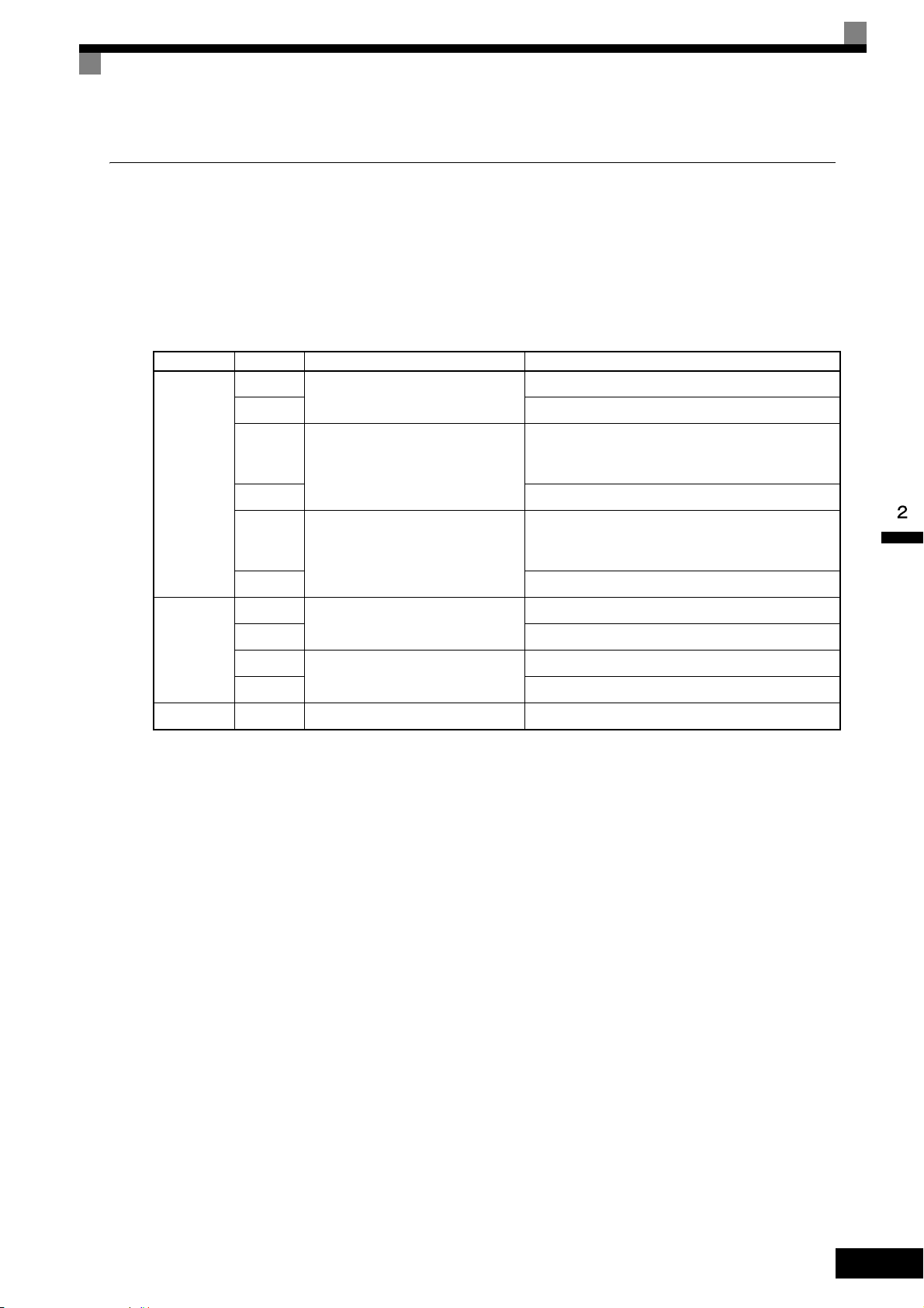
Installing and Wiring Option Cards
PG Speed Control Card Terminals and Specifications
The terminal specifications for the PG Speed Control Cards are given in the following tables.
PG-B2
The terminal specifications for the PG-B2 are given in the following table.
Table 2.12 PG-B2 Terminal Specifications
Terminal No. Contents Specifications
1
Power supply for pulse generator
2 0 VDC (ground for power supply)
3
A-phase pulse input terminal
TA1
4 Pulse input common
5
B-phase pulse input terminal
6 Pulse input common
12 VDC (±5%), 200 mA max
H: +8 to 12 V
L: +1 V max
Maximum response frequency: 30 kHz
H: +8 to 12 V
L: +1 V max
Maximum response frequency: 30 kHz
1
A-phase monitor output terminal
2 A-phase monitor output common
TA2
3
B-phase monitor output terminal
4 B-phase monitor output common
TA3 (E) Shield connection terminal -
Open collector output, 24 VDC, 30 mA max
Open collector output, 24 VDC, 30 mA max
2-27
Page 59

PG-X2
The terminal specifications for the PG-X2 are given in the following table.
Table 2.13 PG-X2 Terminal Specifications
Terminal No. Contents Specifications
1
Power supply for pulse generator
2 0 VDC (ground for power supply)
3 5 VDC (±5%), 200 mA max*
4 A-phase + input terminal
12 VDC (±5%), 200 mA max*
TA1
TA2
TA3 (E) Shield connection terminal -
* 5 VDC and 12 VDC cannot be used at the same time.
5 A-phase - input terminal
6 B-phase + input terminal
7 B-phase - input terminal
8 Z-phase + input terminal
9 Z-phase - input terminal
10 Common terminal 0 VDC (Ground for power supply)
1 A-phase + output terminal
2 A-phase - output terminal
3 B-phase + output terminal
4 B-phase - output terminal
5 Z-phase + output terminal
6 Z-phase - output terminal
7 Control circuit common Control circuit ground
Line driver input (RS-422 level input)
Maximum response frequency: 300 kHz
Line driver output (RS-422 level output)
2-28
Page 60

Wiring
Three-phase
200 VAC (400 VAC)
MxC
4CN
EE
4CN
TA1
1
2
3
4
TA2
TA3 (E)
1
2
3
4
5
6
PG-B2
IM PG
R/L1
S/L2
R/L3
U/T1
V/T2
W/T3
Power supply +12 V
Power supply 0 V
A-phase pulse input (+)
A-phase pulse input (-)
B-phase pulse input (+)
B-phase pulse input (-)
A-phase pulse monitor output
B-phase pulse monitor output
1
TA1
2
3
4
5
6
+12 V
0 V
150 180
150 180
470
150 180
150 180
470
1
2
3
4
TA2
PG power
supply +12 V
A-phase pulse
input
B-phase pulse
input
A-phase
pulses
B-phase
pulses
Division rate
circuit
B-phase pulse
monitor output
A-phase pulse
monitor output
A-phase pulses
B-phase pulses
Wiring examples are provided in the following illustrations for the option cards.
Wiring the PG-B2
Wiring examples for the PG-B2 are provided in the following illustrations.
Installing and Wiring Option Cards
• Shielded twisted-pair wires must be used for signal lines.
• Do not use the pulse generator power supply for anything other than the pulse generator (encoder).
Using it for another purpose can cause malfunctions due to noise.
• The length of the pulse generator wiring must not be more than 100 meters.
• The direction of rotation of the PG can be set in parameter F1-05. The factory preset is Phase A leads
with a forward run command.
When connecting to a voltage-output-type PG (encoder), select a PG that has an output impedance with
•
a current of at least 12 mA to the input circuit photocoupler (diode).
• The pulse monitor dividing ratio can be changed using parameter F1-06 (PG division rate).
• The pulse monitor emitter is connected to common inside the PG-B2. The emitter common must be used
for external circuits.
Fig 2.23 PG-B2 Wiring
Fig 2.24 I/O Circuit Configuration of the PG-B2
2-29
Page 61

Wiring the PG-X2
IMPORTANT
EE
1
2
3
4
5
6
7
1
2
3
4
5
6
7
8
9
10
Three-phase
200 VAC
(400 VAC)
MxC
4CN 4CN
PG-X2
TA1
TA2
TA3 (E)
IM PG
Power supply +12 V
Power supply 0 V
Power supply +5 V
A-phase pulse input (+)
A-phase pulse input (-)
B-phase pulse input (+)
B-phase pulse input (-)
A-phase pulse monitor output
B-phase pulse monitor output
Z-phase pulse monitor output
R/L1
S/L2
U/T1
V/T2
W/T3
T/L3
Wiring examples for the PG-X2 are provided in the following illustrations.
2-30
• Shielded twisted-pair wires must be used for signal lines.
• Do not use the pulse generator power supply for anything other than the pulse generator (encoder).
Using it for another purpose can cause malfunctions due to noise.
• The length of the pulse generator wiring must not be more than 100 meters.
• The direction of rotation of the PG can be set in parameter F1-05 (PG Rotation). The factory preset is
Phase A leads with a forward run command.
Fig 2.25 PG-X2 Wiring
Be sure that the ground terminal is properly grounded using a wire of the recommended size.
200 V class: Ground to 100 Ω or less 400 V class: Ground to 10 Ω
or less
Page 62

Installing and Wiring Option Cards
Wiring Terminal Blocks
Use no more than 100 meters of wiring for PG (encoder) signal lines, and keep them separate from power
lines.
Use shielded, twisted-pair cable for pulse inputs and pulse output monitor wires, and connect the shield to the
shield connection terminal.
Wire Gauges (Same for All Models)
Terminal wire gauges are shown in Table 2.14.
Table 2.14 Wire Gauges
Terminal
Pulse generator power supply
Pulse input terminal
Pulse monitor output terminal
Shield connection terminal M3.5 0.5 to 2
Terminal
Screws
-
Wire Thickness (mm
Stranded wire: 0.5 to 1.25
Single wire: 0.5 to 1.25
2
)
• Shielded, twisted-pair wire
• Shielded, polyethylene-covered, vinyl
sheath cable
(KPEV-S by Hitachi Electric Wire or
equivalent)
Wire Type
Straight Solderless Terminals for Control Circuit Terminals
Yaskawa recommends using straight solderless terminal on signal lines to simplify wiring and improve reliability.
Refer to Straight Solderless Terminal Sizes for specifications.
Closed-Loop Connector Sizes and Tightening Torque
The closed-loop connectors and tightening torques for various wire gauges are shown in Table 2.15.
Table 2.15 Closed Loop Connectors and Tightening Torques
Wire Thickness [mm
0.5
0.75 1.25 - 3.5
1.25 1.25 - 3.5
2 2 - 3.5
2
]
Terminal
Screws
M3.5
Crimp Terminal Size Tightening Torque (N • m)
1.25 - 3.5
0.8
Wiring Method and Precautions
The wiring method is the same as the one used for straight solderless terminals. Refer to page 2-17. Observe
the following precautions when wiring:
• Separate the control signal lines for the PG Speed Control Card from main circuit lines and power lines.
• Connect the shield when connecting to a PG. The shield must be connected to prevent operational errors
caused by noise. Also, do not use any lines that are more than 100 m long. Refer to Fig 2.21 for details on
connecting the shield.
• Connect the shield to the shield terminal (E), but only if the MxC is not affected by noise from peripheral
devices.
• Do not solder the wire ends. Doing so may cause a contact fault.
• When not using straight solderless terminals, strip the wires to a length of approximately 5.5 mm.
2-31
Page 63

Selecting the Number of PG (Encoder) Pulses
Motor speed at maximum frequency output (min−1)
60
× PG rating (p/rev) = 20,000 Hz
TA1
TA3
0 V 12 V
PG
PG
0 V
+12 V
+
+
+
-
-
0 V
+
+
-
-
1
2
3
4
5
6
PG power supply
Capacitor for momentary
power loss
Signals
The setting for the number of PG pulses depends on the model of PG Speed Control Card being used. Set the
correct number for your model.
PG-B2
The maximum response frequency is 32,767 Hz.
Use a PG that outputs a maximum frequency of approximately 20 kHz for the rotational speed of the motor.
Some examples of PG output frequency (number of pulses) for the maximum frequency output are shown in
Table 2.16.
Table 2.16 PG Pulse Selection Examples
Motor's Maximum Speed
−1
)
(min
1800 600 18,000
1500 600 15,000
1200 900 18,000
PG Rating
(p/rev)
PG Output Frequency for Maximum
Frequency Output (Hz)
900 1200 18,000
Note: 1. The motor speed at maximum frequency output is expressed as the sync rotation speed.
2. The PG power supply is 12 V.
3. A separate power supply is required if the PG power supply capacity is greater than 200 mA (If momentary power loss must be handled, use a
backup capacitor or other method).
Fig 2.26 PG-B2 Connection Example
2-32
Page 64

PG-X2
Motor speed at maximum frequency output (min−1)
60
× PG rating (p/rev)f
PG
(Hz) =
TA1
IP12
IG
IP5
A (+)
A (-)
B (+)
B (-)
Z (+)
Z (-)
IG
TA3
PG-X2
1
2
3
4
5
6
7
8
9
10
AC
PG
+
+
+
-
-
0 V
Capacitor for
momentary
power loss
0V +12V
PG power
supply
+12 V
There are 5 V and 12 V PG power supplies.
Check the PG power supply specifications before connecting.
The maximum response frequency is 300 kHz.
Installing and Wiring Option Cards
Use the following equation to calculate the output frequency of the PG (f
PG
).
A separate power supply is needed if the PG power supply requirements are greater than 200 mA. Use a
backup capacitor or some other type of back up power to handle any concerns with momentary loss of power,
Fig 2.27 PG-X2 Connection Example (for a 12 V PG power supply)
2-33
Page 65

Digital Operator and Modes
This chapter describes the various displays screens and functions of the digital operator keypad.
An overview of the operating modes is also provided, as well as how to switch between those
modes.
Digital Operator.............................................................3-2
Operation Modes .......................................................... 3-5
Page 66

Digital Operator
Drive Mode Indicators
FWD: Lit when there is a Forward Run Command input.
REV: Lit when there is a Reverse Run Command input.
SEQ: Lit when the Run Command from the control
circuit terminal is enabled.
REF: Lit when the frequency reference from control
circuit terminals A1 and A2 is enabled.
ALARM: Lit when an error or alarm has occurred.
Data Display
Displays monitor data, parameter numbers, and settings.
Mode Display (Displayed at upper left of data display.)
DRIVE: Lit in Drive Mode.
QUICK: Lit in Quick Programming Mode.
ADV: Lit in Advanced Programming Mode.
VERIFY: Lit in Verify Mode.
A. TUNE: Lit in Auto-Tuning Mode.
Keys
Execute operations such as setting parameters,
monitoring, jogging, and Auto-Tuning.
Frequency Ref
This section describes the displays and functions of the digital operator.
Overview of the Digital Operator
The digital operator key names and functions are described below.
Fig 3.1 Digital Operator Component Names and Functions
Digital Operator Keys
The names and functions of the digital operator keys are described in Table 3.1.
Note: Except in diagrams, keys are referred to by the key names listed in the following table.
Key Name Function
LOCAL/REMOTE key
MENU key
ESC key
JOG key
Table 3.1 Key Functions
Switches between operation via the digital operator (LOCAL) and
control circuit terminal operation (REMOTE).
This key can be enabled or disabled by setting parameter o2-01.
Scrolls through the five main menus:
Operation (-DRIVE-), Quick Setting (-QUICK-), Programming
(-ADV-), Modified Parameters (-VERIFY-), and Auto-Tuning
(-A.TUNE-).
Returns to the current screen to the previous screen display before the
DATA/ENTER key was pressed.
Enables jog operation when the MxC is being operated from the digital operator.
3-2
Page 67

Table 3.1 Key Functions (Continued)
MxC output frequency
Frequency setting
STOP
STOP
RUN
RUN
STOP
Lit Blinking Not lit
Key Name Function
Digital Operator
FWD/REV key
Selects the rotation direction of the motor when the MxC is being
operated from the digital operator.
Selects the digit to be changed when editing parameter settings. The
Right arrow/RESET key
selected digit will flash.
Resets a the MxC after a fault as occurred.
Used to scroll upwards when selecting from a list of parameters.
Up arrow key
Increases the setting that appears on the digital operator screen.
Used to move to the next item or data value.
Used to scroll down when selecting from a list of parameters.
Down arrow key
Increases the setting that appears on the digital operator screen.
Used to move to the next item or data value.
This key is for entering menu items, parameters, and to set values.
DATA/ENTER key
Also used to switch from one display to another.
Parameters cannot be changed when Undervoltage (UV) is detected.
RUN key Sends a run command to have the MxC being operating the motor.
Stops MxC operation.
STOP key
This key can be enabled or disabled when operating from the control
circuit terminal by setting parameter o2-02.
Note: Except in diagrams, keys are referred to using the key names listed in the above table.
There are indicator LEDs on the upper left of the RUN and STOP keys on the digital operator. These indicators will light and flash to indicate operating status.
An indicator LED on the RUN key will flash and the STOP key LED will light during initial excitation of the
dynamic brake. The relationship between the indicators on the RUN and STOP keys and the MxC status is
shown in the Fig 3.2.
Fig 3.2 RUN and STOP Indicator LEDs
3-3
Page 68

The following table shows the relationship between the indicators on the RUN and STOP keys as well as the
MxC operation status.
The LED indicators can be on, off, or flash to indicate the operating status.
Table 3.2 Relation of MxC to RUN and STOP LED Indicators
Priority
RUN
Indicator
STOP
Indicator
MxC
Status
1 Stopped Power supply has been shut off.
Emergency stop
• A Stop Command is sent from the digital operator when using the control circuit terminals to operate the MxC.
• An Emergency Stop Command was sent from the control circuit terminal.
2 Stopped*
The MxC has been switched from LOCAL to REMOTE when the Run
Command is still sent from one of the external terminals (LOCAL = operation using the digital operator, REMOTE: operation using the control
circuit terminals).
Switched from the Quick or Advanced Quick Programming Mode to the
Drive Mode while the Run Command is being sent via an external terminal.
The MxC is trying to run at a frequency below the minimum output fre-
3 Stopped
quency.
The Run Command is carried out when the External Baseblock Command using the multi-function contact input terminal is issued.
4 Stopped Stopped
The MxC is decelerating to a stop.
During DC injection braking when using the multi-function contact input
5 Running
terminal.
During initial excitation of DC injection braking while the MxC is
stopped.
Conditions
During emergency deceleration
6 Running
• Stop Command is sent from the digital operator when operating the
MxC using the control circuit terminals.
• Emergency Stop Command is sent from the control circuit terminal.
7 Running
Note: : Lit : Flashing : Not lit
* If planning to run the MxC again, first turn off the Run Command and Emergency Stop Command from the control circuit terminal, and then re-send the
Run Command.
Run Command is issued.
During initial excitation of DC injection braking when starting the MxC.
3-4
Page 69

Operation Modes
This section describes the operation modes available in the MxC, and how to switch between modes.
MxC Modes
Parameters and monitoring functions in the MxC are organized into groups called “modes”. These modes
make it easier to read and set parameters. Their are five separate modes available in the MxC.
The five modes and their primary functions are shown in the Table 3.3.
Table 3.3 Modes
Mode Primary functions
A Run Command may be entered to start the motor when viewing this mode.
Drive Mode
Quick Programming Mode
Use this mode when monitoring values such as frequency references or output current, displaying fault information, or displaying the fault history.
Use this mode to set and monitor the most commonly used parameters, as well as
operate the MxC.
Operation Modes
Advanced Programming Mode Use this mode to reference and set all parameters.
Verify Mode
Auto-Tuning Mode*
* Always perform Auto-Tuning with the motor before operating in Open Loop or Flux Vector Control. The Auto-Tuning Mode cannot be entered while the
MxC is running, or when an error has occurred. The default setting of the MxC is for Open Loop Vector Control (A1-02 = 2).
Use this mode to read/set parameters that have been changed from their original
default values.
Use this mode when running a motor with unknown motor characteristics in Open
Loop or Flux Vector Control. In this mode, the MxC automatically calculates the
motor characteristics, then enters those values to the motor parameters.
Also used to measure the motor line-to-line resistance.
3-5
Page 70

Switching Between Modes
IMPORTANT
Frequency Ref
-DRIVE-
U1-02=60.00Hz
U1-03=10.05A
** Main Menu **
-DRIVE-
Operation
** Main Menu **
-QUICK-
Quick Setting
** Main Menu **
-ADV-
Programming
** Main Menu **
-VERIFY-
Modified Consts
** Main Menu **
-A.TUNE-
Auto-Tuning
Rdy
U1- 01=60.00Hz
Monitor
-DRIVE-
U1-02=60.00Hz
U1-03=10.05A
Rdy
U1 - 01=60.00Hz
MENU
ESC
DATA
ENTER
Control Method
-QUICK-
A1-02=2
Initialization
-ADV-
A1 - 00=1
Select Language
None Modified
-VERIFY-
Reference Source
-DRIVE-
U1-02=60.00Hz
U1-03=10.05A
U1- 01=60.00Hz
Frequency Ref
-DRIVE-
(0.00←→60.00)
"0.00Hz"
Rdy
U1- 01=060.00Hz
MENU
MENU
MENU
MENU
>
RESET
ESC
DATA
ENTER
ESC
ESC
DATA
ENTER
Control Method
-QUICK-
A1-02= 2
Open Loop Vector
DATA
ENTER
ESC
DATA
ENTER
ESC
DATA
ENTER
Select Language
-ADV-
A1-00 =0
*1*
English
ESC
-ADV-
Select Language
English
ESC
DATA
ENTER
>
RESET
DATA
ENTER
ESC
DATA
ENTER
ESC
DATA
ENTER
DATA
ENTER
ESC
The parameter number will be displayed if a
parameter has been changed. Press the
DATA/ENTER key to enable the change.
Monitor display Setting display
Mode selection
display
Display at startup
Open Loop Vector
Tuning Mode Sel
-A.TUNE-
Standard Tuning
"0"
Tuning Mode Sel
-A.TUNE-
Standard Tuning
"0"
*2*
Rdy
A1- 00= 0
*1*
T1- 01=0 1
*0*
T1- 01= 0
*0*
*2*
The mode selection display will appear when the MENU key is pressed from a monitor or setting display.
Press the MENU key from the mode selection display to switch between the modes.
Press the DATA/ENTER key from the mode selection key to monitor data and from a monitor display to
access the setting display.
3-6
Fig 3.3 Mode Transitions
After using the digital operator to issue a Run Command, press the MENU key to select the Drive Mode (the
Drive Mode display will appear on the digital operator screen). Next, press the DATA/ENTER key while in the
Drive Mode display to bring up the monitor display screen. The MxC will not accept a Run Command if any
other screen is displayed. The monitor display screen in the Drive Mode will appear whenever the power is
first turned on.
Page 71

Operation Modes
Frequency Ref
-DRIVE-
U1-02=60.00Hz
U1-03=10.05A
** Main Menu **
-DRIVE-
Operation
** Main Menu **
-QUICK-
Quick Setting
** Main Menu **
-ADV-
Programming
** Main Menu **
-VERIFY-
Modified Consts
** Main Menu **
-A.TUNE-
Auto-Tuning
U1- 01=60.00Hz
Monitor
-DRIVE-
U1-02=60.00Hz
U1-03=10.05A
U1 - 01=60.00Hz
MENU
ESC
DATA
ENTER
Frequency Ref
-DRIVE-
U1-02=60.00Hz
U1-03=10.05A
U1- 01=60.00Hz
Frequency Ref
-DRIVE-
(0.00←→60.00)
0.00Hz
U1 -01= 060.00Hz
MENU
MENU
MENU
MENU
㧪
RESET
DATA
ENTER
ESC
DATA
ENTER
Monitor display Default displayMode selection
display
Display at startup
Fault Trace
-DRIVE-
U2-02= OV
U2-03=60.00Hz
U2 -01=OC
Fault History
-DRIVE-
U3-02= OV
U3-03= OH
U3 -01= OC
Output Freq
-DRIVE-
U1-04= 2
U1-03=10.05A
U1- 02=60.00Hz
FAN Elapsed Time
-DRIVE-
U1-01=60.00Hz
U1-02=60.00Hz
U1- 40 = 10H
1 2
1 2
Last Fault
-DRIVE-
U3-02=OV
U3-03=OH
U3 - 01 = OC
Fault Message 2
-DRIVE-
U3-03= OH
U3-04= UV
U3 - 02 = OV
㧪
RESET
ESC
5 6
5 6
A B
A B
Current Fault
-DRIVE-
U2-02=OV
U2-03=60.00Hz
U2 - 01 = OC
Last Fault
-DRIVE-
U3-03=60.00Hz
U3-04=60.00Hz
U2 - 02 = OV
3 4
3 4
㧪
RESET
ESC
U2 -01= OC
U2 - 02= OV
Over Current
DC Bus Overvolt
DATA
ENTER
ESC
DATA
ENTER
ESC
U3 - 01= OC
Over Current
DATA
ENTER
ESC
U3 - 02= OV
DC Bus Overvolt
DATA
ENTER
ESC
The fault name will be
displayed if the DATA/ENTER
key is pressed while a parameter
is being displayed for which a
fault code is being displayed.
Rdy
Rdy
Rdy
Rdy
Rdy
Rdy
Rdy
Rdy
Rdy Rdy
Rdy
Rdy
The default display will not be
displayed when using an
analog reference.
ESC
Monitor
-DRIVE-
U1-04= 2
U1-03=10.05A
U1 - 02=60.00Hz
Rdy
㧪
RESET
ESC
Monitor
-DRIVE-
U1-01=60.00Hz
U1-02=60.00Hz
U1 -40 = 10H
Rdy
㧪
RESET
ESC
Rdy
Rdy
Rdy
Fault Trace
-DRIVE-
U3-03=60.00Hz
U3-04=60.00Hz
U2 -02 = OV
Rdy
㧪
RESET
ESC
Fault Message 2
-DRIVE-
U3-03= OH
U3-04= UV
U3 - 02 = OV
Rdy
㧪
RESET
ESC
DATA
ENTER
Drive Mode
Once in the Drive Mode, the user can now instruct the MxC to begin operating the motor. The following monitor displays can be viewed while in the Drive Mode: frequency reference, output frequency, output current,
output voltage, as well as fault information and the fault history.
When b1-01 (Frequency Reference Selection) is set to 0, the frequency can be changed from the value that
appears in the frequency setting display. Use the up arrow and right arrow keys to change parameter settings.
Any changes will be saved once the DATA/ENTER key is pushed.
How to Operate the MxC in the Drive Mode
Key operations in the Drive Mode are shown in the following figure.
Fig 3.4 Operations in Drive Mode
3-7
Page 72

Note: When changing the display with the up arrow and down arrow keys, the next display after the one for the last parameter number will be the one for the
IMPORTANT
first parameter number. For example, if the up arrow key is pressed when U1-01 is displayed, the last parameter will be displayed instead of U1-02.
This is indicated in the figures by the letters A and B and the numbers 1 to 6.
The display for the first monitor parameter (frequency reference) will be displayed when power is turned on.
The monitor item displayed at startup can be set in o1-02 (Monitor Selection after Power Up).
Operation cannot be started from the mode selection display.
3-8
Page 73

Quick Programming Mode
** Main Menu **
-DRIVE-
Operation
** Main Menu **
-QUICK-
Quick Setting
** Main Menu **
-ADV-
Programming
** Main Menu **
-VERIFY-
Modified Consts
** Main Menu **
-A.TUNE-
Auto-Tuning
MENU
Control Method
-QUICK-
A1-02=2
*2*
Open Loop Vector
Reference Source
-QUICK-
b1-01=1
*1*
Terminals
MENU
MENU
MENU
MENU
ESC
DATA
ENTER
DATA
ENTER
ESC
Run Source
-QUICK-
b1-02=1
*1*
Terminals
Monitor display
Setting display
Mode selection display
MOL Fault Select
-QUICK-
L1-01=1
*1*
Std Fan Cooled
Terminal AM Gain
-QUICK-
(0.00←→2.50)
0.50
H4-05=0.50
A B
A B
Control Method
-QUICK-
A1-02= 2
*2*
Open Loop Vector
Reference Source
-QUICK-
b1-01= 1
*1*
Terminals
DATA
ENTER
ESC
Run Source
-QUICK-
b1-02= 1
*1*
Terminals
DATA
ENTER
ESC
Terminal AM Gain
-QUICK-
(0.00㨪2.50)
0.50
H4-05= 0 .50
MOL Fault Select
-QUICK-
L1-01= 1
*1*
Std Fan Cooled
DATA
ENTER
ESC
DATA
ENTER
ESC
In the Quick Programming Mode, the user can set the basic parameters required to test run the MxC.
Parameters can be changed from the setting display screen. Use the up arrow, down arrow, and right arrow
keys to change parameter settings. Any changes will be saved once the DATA/ENTER key is pushed.
Refer to Chapter 5 MxC Parameters for details on the parameters displayed in Quick Programming Mode.
Making Changes in the Quick Programming Mode
Key operations in Quick Programming Mode are shown in the following figure.
Operation Modes
Fig 3.5 Operations in Quick Programming Mode
3-9
Page 74

Advanced Programming Mode
A1- 00= 0
** Main Menu **
-DRIVE-
Operation
** Main Menu **
-QUICK-
Quick Setting
** Main Menu **
-ADV-
Programming
** Main Menu **
-VERIFY-
Modified Consts
** Main Menu **
-A.TUNE-
Auto-Tuning
MENU
Initialization
-ADV-
A1-00=1
Select Language
MENU
MENU
MENU
MENU
ESC
DATA
ENTER
Select Language
-ADV-
A1- 00 =0
English
ESC
-ADV-
Select Language
English
*1*
ESC
DATA
ENTER
㧪
RESET
Monitor display Setting displayMode selection display
PID Control
-ADV-
b5-01=0
PID Mode
ESC
ESC
DATA
ENTER
㧪
RESET
Control Method
-ADV-
A1- 02 =2
Open Loop Vector
PID Mode
-ADV-
b5- 01 =0
Disabled
Control Method
-ADV-
A1- 02= 2
Open Loop Vector
ESC
DATA
ENTER
*2*
*1*
*2*
1 2
1 2
PID Mode
-ADV-
b5-01= 0
Disabled
*0*
*0*
Fb los Det Time
-ADV-
(0.00㨪25.5)
1.0Sec
b5- 14= 1.0Sec
Fb los Det Time
-ADV-
(0.00㨪25.5)
1.0Sec
b5-14=01.0Sec
ESC
DATA
ENTER
3 4
3 4
Torque Limit
-ADV-
L7-01=200%
Fwd Torque Limit
ESC
ESC
DATA
ENTER
㧪
RESET
ESC
DATA
ENTER
5 6
5 6
Fwd Torque Limit
-ADV-
(0㨪300)
200%
L7- 01= 200%
Fwd Torque Limit
-ADV-
(0㨪300)
200%
L7-01= 2 00%
Torq Lmt Rev Rgn
-ADV-
(0㨪300)
200%
L7-04= 2 00%
Fwd Torque Limit
-ADV-
(0㨪300)
200%
L7- 04= 200%
A B
A B
Initialization
-ADV-
A1-02 =2
Control Method
ESC
㧪
RESET
PID Control
-ADV-
b5 - 14= 1.0Sec
Fb los Det Time
ESC
㧪
RESET
Fwd Torque Limit
-ADV-
L7- 04= 200%
Torque Limit
ESC
㧪
RESET
In the Advanced Programming Mode, the user can access all MxC parameters to change settings or simply
monitor performance.
The user can change the setting values saved to each parameter. For example, the user can adjust the frequency
the motor is running at by using the arrow keys on the keypad. The new value for the parameter will be saved
once the DATA/ENTER key is pressed.
Refer to Chapter 5 Parameters for a list and description of parameters.
Making Changes in the Advanced Programming Mode
The following diagram show examples of how to the use the digital operator key pad in the Advanced Programming Mode.
3-10
Fig 3.6 Operations in Advanced Programming Mode
Page 75

Operation Modes
Frequency Ref
-DRIVE-
U1-02=60.00Hz
U1-03=10.05A
Rdy
U1- 01=60.00Hz
** Main Menu **
-DRIVE-
Operation
** Main Menu **
-QUICK-
Quick Setting
** Main Menu **
-ADV-
Programming
Initialization
-ADV-
A1-00=1
Select Language
Accel Time 1
-ADV-
(0.0←→6000.0)
10.0Sec
C1-00= 10.0Sec
Accel Time 1
-ADV-
(0.0←→6000.0)
10.0Sec
C1-01= 0 010.0Sec
Accel Time 1
-ADV-
(0.0←→6000.0)
10.0Sec
C1-01= 0 010.0Sec
Accel Time 1
-ADV-
(0.0←→6000.0)
10.0Sec
C1-01= 00 10.0Sec
Accel Time 1
-ADV-
(0.0←→6000.0)
10.0Sec
C1-01= 00 20.0Sec
Entry Accepted
-ADV-
Accel Time 1
-ADV-
(0.0←→6000.0)
10.0Sec
C1- 01= 20.0Sec
Setting Parameters
The procedure described below explains how to change C1-01 (Acceleration Time 1) from 10 s to 20 s.
Table 3.4 Changing Parameter Settings in the Advanced Programming Mode
Step
No.
1 First make sure that the MxC has been powered up.
2 Press the MENU key to scroll to “Operation” menu.
3 Press the MENU key to scroll to “Quick Setting” menu.
Digital Operator Display Description
4 Press the MENU key to scroll to “Programming” menu.
5 Press the DATA/ENTER key to enter “Programming” menu.
6 Press the up arrow key until parameter C1-01 is displayed.
7
Push the DATA/ENTER key to access setting display. The setting of C1-01
(10.00) is displayed.
8 Press the right arrow key to move the flashing digit to the right.
9 Press the up arrow key to increase the value to 20.00 s.
10 Press the DATA/ENTER key to save the change.
11 “Entry Accepted” is displayed for 1.0 s.
12 The digital operator screen will return to the C1-01 display.
3-11
Page 76

External Fault Setting Procedure
** Main Menu **
-DRIVE-
Operation
** Main Menu **
-QUICK-
Quick Setting
** Main Menu **
-ADV-
Programming
** Main Menu **
-VERIFY-
Modified Consts
** Main Menu **
-A.TUNE-
Auto-Tuning
MENU
Digital Inputs
-ADV-
H1-01=24
Terminal S3 Sel
MENU
MENU
MENU
MENU
ESC
DATA
ENTER
Terminal S3 Sel
-ADV-
H1- 01 =24
External Fault
ESC
ESC
DATA
ENTER
㧪
RESET
Monitor display Setting displayMode selection display
*24*
1 2
A B
A B
Digital Inputs
-ADV-
H2-01= 0
Term M1-M2 Sel
Terminal S4 Sel
-ADV-
H1- 02 =14
*14*
Terminal S8 Sel
-ADV-
H1- 08 =08
Ext BaseBlk N.O.
*08*
Terminal S3 Sel
-ADV-
H1- 01= 24
NO/Always Det
*24*
Coast to Stop
Terminal S3 Sel
-ADV-
H1- 01= 25
NC/Always Det
*24*
Coast to Stop
Terminal S3 Sel
-ADV-
H1- 01= 26
NO/During RUN
*24*
Coast to Stop
Terminal S3 Sel
-ADV-
H1- 01= 27
NC/During RUN
*24*
Coast to Stop
Terminal S3 Sel
-ADV-
H1- 01= 2F
NC/During RUN
*24*
Alarm Only
3 4
3 4
1 2
DATA
ENTER
Fault Reset
Terminal S4 Sel
-ADV-
H1-02 =14
Digital Inputs
ESC
㧪
RESET
"24"
"14"
"08"
Terminal S8 Sel
-ADV-
H1-08 =08
Digital Inputs
ESC
㧪
RESET
The following diagram shows how to set one of the multi-function contact inputs to be triggered when an
external fault is detected. To make the setting changes, the MxC must be in the Advanced Programming
Mode.
3-12
Fig 3.7 External Fault Function Setting Example
Page 77

Operation Modes
** Main Menu **
-DRIVE-
Operation
** Main Menu **
-QUICK-
Quick Setting
** Main Menu **
-ADV-
Programming
** Main Menu **
-VERIFY-
Modified Consts
** Main Menu **
-A.TUNE-
Auto-Tuning
MENU
MENU
MENU
MENU
MENU
Monitor display Setting displayMode selection display
DATA
ENTER
Reference Source
-VERIFY-
b1-01=0
*0*
Terminals
ESC
DATA
ENTER
Accel Time 1
-VERIFY-
(0.0㨪6000.0)
10.0Sec
C1-01=200.0Sec
A B
A B
Reference Source
-VERIFY-
b1-01= 0
*0*
Terminals
DATA
ENTER
ESC
DATA
ENTER
ESC
DATA
ENTER
ESC
Input Voltage
-VERIFY-
(155㨪255)
200VAC
E1-01=200VAC
Motor Rated FLA
-VERIFY-
(0.32㨪6.40)
1.90A
E2-01=2.00A
Motor Rated FLA
-VERIFY-
(0.32㨪6.40)
1.90A
E2-01= 2.00A
Input Voltage
-VERIFY-
(155㨪255)
200V
E1-01= 200VAC
Accel Time 1
-VERIFY-
(0.0㨪6000.0)
10.0Sec
C1-01=0200.0Sec
DATA
ENTER
ESC
"1"
"1"
Verify Mode
The Verify Mode displays any parameters that have been changed from their default settings. This includes all
parameters that were changed by the user in the Programming Mode, and all parameters that were changed
when Auto-Tuning was performed. If no parameter settings have been changed, then the Verify Mode display
window will read, “None”.
The Verify Mode will not show parameters belonging to the A1: Initialization Settings group (i.e., all parameters that start with A1appear if it has been changed from its default value.
The user can also change parameter settings while in the Verify Mode. Just as in the Programming Mode, use
the up arrow, down arrow, and SHIFT/RESET keys to adjust any setting values. Save changes by pressing the
DATA/ENTER key.
Using the Verify Mode
), even if those parameters have been changed. The exception is A1-02, which will
The example below demonstrates how to use the Verify Mode to view parameters that have been set to values
different from their default settings. In the example, the following parameters have been changed: b1-01 (Reference Selection), C1-01 (Acceleration Time 1), E1-01 (Input Voltage Setting), and E2-01 (Motor Rated Current).
Fig 3.8 Operations in Verify Mode
3-13
Page 78

Auto-Tuning Mode
This menu is used to Auto-Tune the MxC in order to calculate the required motor parameters to optimize
motor performance. Ideally, perform Auto-Tuning with the motor uncoupled from the load.
When the motor cannot be disconnected from the load, perform static or terminal resistance Auto-Tuning. To
set motor parameters manually, contact your Yaskawa representative. Follow the key operations in Fig 3.9 to
access the Auto-Tuning Menu.
The MxC’s Auto-Tuning function automatically determines the optimal motor parameters settings. This is
fundamentally different from the Auto-Tuning function in a servo system, which instead determines the size of
a load. The default setting of the MxC is for Open Loop Vector Control.
3-14
Page 79

Operation Modes
IMPORTANT
START GOAL
** Main Menu **
-DRIVE-
Operation
** Main Menu **
-QUICK-
Quick Setting
** Main Menu **
-ADV-
Programming
** Main Menu **
-VERIFY-
Modified Consts
** Main Menu **
-A.TUNE-
Auto-Tuning
MENU
MENU
MENU
MENU
MENU
Monitor display Setting displayMode selection display
DATA
ENTER
Tuning Mode Sel
-A.TUNE-
T1- 01 =0 *0*
ESC
DATA
ENTER
A
DATA
ENTER
ESC
DATA
ENTER
ESC
RUN
Auto-Tuning
-A.TUNE-
Press RUN key
Tuning Ready ?
Tune Proceeding
-A.TUNE-
48.0Hz/10.5A
DATA
ENTER
ESC
Standard Tuning
Tuning Mode Sel
-A.TUNE-
ޓT1- 01 = 0 *0*
Rated Frequency
-A.TUNE-
T1- 05 = 60.0Hz
(0.0㨪120.0)
0.0Hz
Number of Poles
-A.TUNE-
T1- 06 = 4
(2㨪48)
4
Rated Frequency
-A.TUNE-
T1- 05 = 0 60.0Hz
(0.0㨪120.0)
0.0Hz
Number of Poles
-A.TUNE-
T1- 06 = 04
(2㨪48)
4
A
Rdy
Tune Aborted
-A.TUNE-
STOP key
STOP
The display will
automatically
change depending
on the status of
autotuning.
Standard Tuning
30%㩀㩧㩢㨸㨽
START GOAL
Tune Proceeding
-A.TUNE-
48.0Hz/10.5A
30%㩀㩧㩢㨸㨽
Tune Successful
-A.TUNE-
30%㩀㩧㩢㨸㨽
Tune Successful
Tune Proceeding
-A.TUNE-
"0"
"0"
0.0Hz/0.0A
Executing Auto-Tuning
Set the motor output power (kW), rated voltage, rated current, rated frequency, rated speed, and number of
poles as specified on the motor nameplate. Next, press RUN. The motor will begin to rotate, and the MxC will
automatically set motor parameters based on the information provided from the nameplate and measurements
taken during the Auto-Tuning process.
Auto-Tuning requires that motor data be entered from the specifications indicated on the motor nameplate.
Auto-Tuning cannot be executed without this information, and cannot be started from the motor rated voltage
display.
Set parameter values when they are displayed by using the up, down, and right arrow keys. Changes are saved
once DATA/ENTER key is pushed.
The following example shows how to perform Auto-Tuning in the Open Loop Vector Control Method while
operating the motor (without switching to motor 2).
Fig 3.9 Screen Displays in the Auto-Tuning Mode
The screen displays in the Auto-Tuning Mode depend on the control method the MxC is operating in (V/f,
Open Loop Vector, or Flux Vector). If a fault occurs during Auto-Tuning, refer to Chapter 7 Troubleshooting.
3-15
Page 80

Test Run
This chapter describes the procedures for Test Run of the MxC and provides an example of Test
Run.
Test Run Procedure ......................................................4-2
Test Run Procedures ....................................................4-3
Notes on Tuning the MxC ........................................... 4-14
Page 81

Test Run Procedure
START
Installation
Wiring
Turn on power.
Confirm status.
Basic settings
(Quick Programming Mode)
Select operating
method.
Settings according
to control method
Application settings
(Advanced Programming Mode)
No-load operation
Loaded operation
Optimum adjustments and
Parameter settings
Check/save parameters.
END
YES
V/f
(A1-02 = 0)
Vector (A1-02 = 2 or 3) *2
Set E1-03.
V/f default: 200 V/60 Hz(400 V/60 Hz)
YES
NO
V/f Control?
Motor cable over
50 m or heavy load possibly
causing motor to stall or
overload?
Stationary Auto-Tuning for
line-to-line resistance only
Rotational Auto-Tuning *3
*1
*1 If the motor cable changes to 50 m or longer for the actual
installation, perform stationary Auto-Tuning for the line-to-line
resistance only on-site.
*2 The default control method is Open Loop Vector Control
(A1-02 = 2).
*3 If the maximum output frequency is different from the base
frequency, set the Maximum Output Frequency (E1-04) to the
value of the base frequency after Auto-Tuning.
Test run the MxC as shown in the flowchart below:
4-2
Fig 4.1 Test Run Flowchart
Page 82

Test Run Procedures
01
Frequency Ref
-DRIVE-
UV
PS Undervolt
This section describes the procedure for performing a test run after the MxC is fully connected.
Switching the Power On
Confirm all of the following items first, and then turn on the power supply.
• Make sure the power supply voltage is correct.
200 V class: 3-phase 200 to 220 VDC, 50/60 Hz
400 V class: 3-phase 380 to 480 VDC, 50/60 Hz
If connecting an MxC to a power supply with high impedance, such as a Slidax, the power-supply voltage
may rise during regeneration. Contact your Yaskawa representative for details.
• Use a power supply with a capacity that is the same or greater than the MxC capacity.
• Make sure that the motor output terminals (U, V, W) and the motor are properly connected.
• Make sure that the MxC control circuit terminal and the control device are wired correctly.
• Set all MxC control circuit terminals to off.
• When using a PG Speed Control Card, make sure that it is wired correctly.
• Make sure that the motor is not connected to the mechanical system (no-load status)
Test Run Procedures
Checking the Display Status
Assuming there are no problems, the digital operator will display the following message when the power is
switched on:
-DRIVE-
-DRIVE-
Display during normal
operation when the unit is
first powered up.
Frequency Ref
Frequency Ref
01
U1- 01= 60.0 0Hz
U1-01= 0 0 0.0 0Hz
U1-02=60.00Hz
U1-03=10.05A
When a fault has occurred, information concerning the fault will be displayed instead of the message shown
above. The user should refer to Chapter 7 Troubleshooting for information on how to remedy a fault situation.
Below is and example of the digital operator display when a fault occurs.
Operator display when a fault
has occurred.
Rdy
The output frequency reference appears
on the digital operator screen.
The display will differ depending on the
type of fault.
A example on the left shows a low voltage
alarm.
4-3
Page 83

Basic Settings
Switch to the Quick Programming Mode (“QUICK” will be displayed on the LCD screen), and then set the
following parameters. Refer to Chapter 3 Digital Operator and Modes for digital operator operating procedures and to Chapter 5 Parameters and Chapter 6 Parameter Settings by Function for details on the Parameters.
Parameters that must be set are listed in Table 4.1 and those that are set according to the application are listed
in Table 4.1.
Table 4.1 Parameters that Must Be Set
Parameter
Number
A1-02
b1-01
b1-02
b1-03
C1-01
Name Description
Selects the Control Method.
Control Method
Selection
Frequency Reference Selection
Run Source
Stopping Method
Selection
Acceleration
Time 1
0: V/f Control Method without a PG encoder
2: Open Loop Vector
3: Flux Vector (Closed Loop Vector)
Selects the frequency reference input source.
0: Operator - Digital preset speed U1-01 or d1-
01 to d1-17.
1: Terminals - Analog input terminal A1 (or
terminal A2 based on parameter H3-09).
2: Serial Com - Modbus RS-422/485 terminals
R+, R-, S+, and S-.
3: Option PCB - Option card connected on
2CN.
Selects the Run Command input source.
0: Operator - RUN and STOP keys on digital
operator.
1: Terminals - Contact closure on terminals S1
or S2.
2: Serial Com - Modbus RS-422/485 terminals
R+, R-, S+, and S-.
3: Option PCB - Option card connected on
2CN.
Selects the stopping method when the Run
Command is removed.
0: Decelerate to stop
1: Coast to Stop
2: DC Injection to Stop
3: Coast with Timer (A new Run Command is
ignored if received before the timer expires).
Sets the time to accelerate from zero to maxi-
mum frequency.
Setting
Range
0, 2, or 3 2 5-7
0 to 3 1
0 to 3 1
*1
0 to 3
0.0 to 6000.0
*2
Default Page
0
10.0 s
5-9
6-2
6-67
6-84
5-9
6-8
6-67
6-84
5-9
6-11
5-16
6-17
4-4
C1-02
C6-02
d1-01 to d1-
04 and d1-
17
Deceleration
Time 1
Carrier Frequency Selection
Frequency
References 1 to 4
and Jog
Frequency
Reference
Sets the time to decelerate from maximum frequency to zero.
Select carrier frequency
2: 4.0 kHz
4: 8.0 kHz
6: 12.0 kHz
Set the required speed references for multi-step
speed operation or jogging.
0.0 to 6000.0
*2
2, 4, or 6
0.00 to 120.00
*3
10.0 s
25-19
d1-01 to
d1-04:
0.00 Hz
d1-17:
6.00 Hz
5-16
6-17
5-20
5-21
Page 84
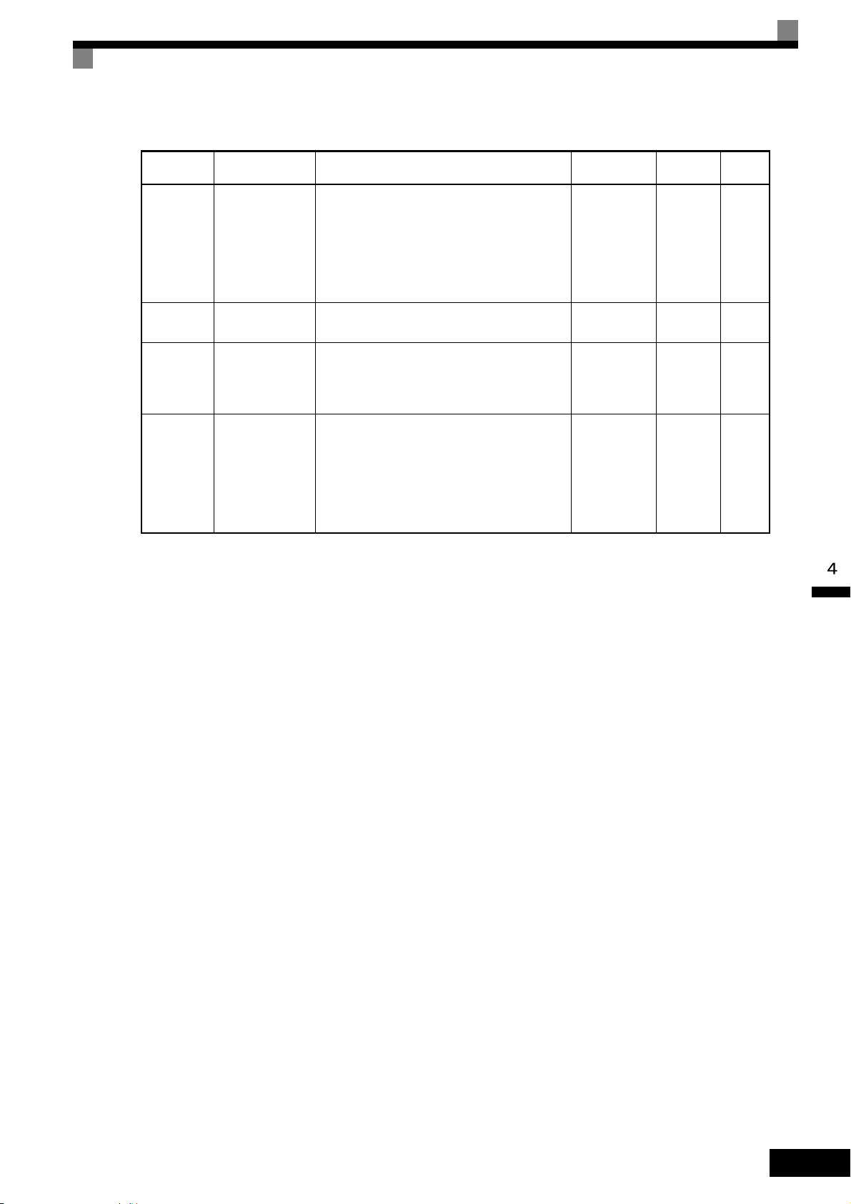
Table 4.1 Parameters that Must Be Set (Continued)
Test Run Procedures
Parameter
Number
Name Description
Setting
Range
Default Page
Setting for
general-
E2-01
Motor Rated Current
Sets the motor nameplate full load current in
amperes (A). This value is automatically set
during Auto-Tuning.
10% to 200%
of MxC's rated
current
purpose
motor of
same
5-26
6-51
6-102
capacity
as MxC
*4
F1-01
H4-02 and
H4-05
PG Parameter
FM and AM
terminal output
Gain
Sets the number of pulses per revolution (PPM)
of the encoder (pulse generator).
Set the voltage level gain for the multi-function
analog output 1 (H4-02) and 2 (H4-05).
Set the number of multiples of 10 V to be output
as the 100% output for the monitor item.
0 to 60000 600 5-29
H4-02:
0.00 to 2.50
1.00
H4-05:
5-41
0.50
Sets the motor thermal overload protection
(OL1) based on the cooling capacity of the
L1-01
Motor Overload
Protection Selection
motor.
0: Disabled
1: General-purpose motor protection
0 to 3 1
5-43
6-51
2: Inverter motor protection
3: Vector motor protection
* 1. 0 or 1 for Flux Vector Control.
* 2. The setting range for accel/decel times depends on the setting of C1-10 (Accel/Decel Time Setting Unit). If C1-10 is set to 0, the setting range is 0.00 to
600.00 (s).
* 3. Fixed to 2:4 kHz for V/f.
For Open Loop Vector Control, can select from 2:4 kHz or 4:8 kHz (Fixed to 2: 4 kHz for 200 V class MxC for 45 kW and 400 V class MxCs for 22 kW
and 45 kW).
* 4. Displayed only while using Flux Vector Control.
4-5
Page 85

Settings for the Control Methods
START
YES
V/f Control?
Motor cable over
50 m or heavy load possibly
causing motor to stall
or overload?
NO
Vector (A1-02 = 2 or 3) *1
Set E1-03.
V/f default: 200 V/60 Hz(400 V/60 Hz)
NO
YES
END
*2
Control method selection
Rotational Auto-Tuning
Stationary Auto-Tuning for
line-to-line resistance only
V/f
(A1-02 = 0)
Auto-Tuning methods depend on the control method set for the MxC. Make the settings required by the control method.
Overview of Settings
Make the required settings in the Quick Programming Mode and Auto-Tuning Mode according to the following flowchart.
Note: If the motor cable is 50 m or longer, perform Stationary Auto-Tuning onsite for the line-to-line resistance only.
* 1. The default setting of the MxC is for Open Loop Vector Control (A1-02 = 2).
* 2. If the maximum output frequency is different from the base frequency, set the Maximum Output Frequency (E1-04) to the value of the base frequency
after Auto-Tuning the MxC.
Fig 4.2 Settings Parameters in Accordance with the Control Method
4-6
Page 86

Setting the Control Method
Any of the following three control methods can be set.
Control Method
V/f Control
Parameter
Setting
A1-02 = 0 Voltage/frequency ratio fixed control Variable speed control
Test Run Procedures
Basic Control Main Applications
Open Loop Vector
Control
Flux Vector Control
Note: The motor and MxC must be connected 1:1. The MxC is capable of stably operating motors capacities rated at 75% to 100% of the capacity of the
MxC.
A1-02 = 2
(default setting)
A1-02 = 3 Flux Vector Control High-performance control with a PG
Current vector control without a PG
Variable speed control, applications
requiring speed and torque accuracy
using vector control without a PG
V/f Control Method (A1-02 = 0)
• Set either one of the fixed patterns (0 to E) to parameter E1-03 (V/f Pattern Selection), or enter “F” to spec-
ify a user-set pattern as required for the motor and load characteristics in E1-04 to E1-13 in Advanced Programming Mode.
Simple operation of a general-purpose motor at 50 Hz: E1-03 = 0
Simple operation of a general-purpose motor at 60 Hz: E1-03 = F (default) or 1
If E1-03 = F, the default setting in the user setting
from E1-04 to E1-13 are for 60 Hz
• Perform Stationary Auto-Tuning for the line-to-line resistance only if the motor cable is 50 m or longer for
the actual installation or the load is heavy enough to produce stalling. Refer to the following section on
Auto-Tuning for details on Stationary Auto-Tuning for the line-to-line resistance only.
Open Loop Vector Control (A1-02 = 2)
Perform Rotational Auto-Tuning. Refer to the following section on Auto-Tuning for details on Rotational
Auto-Tuning.
Flux Vector Control (A1-02 = 3)
Perform Rotational Auto-Tuning. Refer to the following section on Auto-Tuning for details on Rotational
Auto-Tuning.
4-7
Page 87

Auto-Tuning
Use the following procedure to perform Auto-Tuning if using the vector control method or when using a long
motor cable. Auto-Tuning calculates the motor characteristics and automatically sets all necessary motor
parameters.
If the control method was changed after Auto-Tuning, be sure to perform Auto-Tuning again.
The following types of Auto-Tuning are possible in the MxC:
• Rotational Auto-Tuning
• Stationary Auto-Tuning for line-to-line resistance only
• Stationary Auto-Tuning 2
Precautions Before Performing Auto-Tuning
Read the following precautions before Auto-Tuning the MxC.
• Auto-Tuning the MxC is fundamentally different from Auto-Tuning a servo system. The MxC Auto-Tun-
ing automatically adjusts motor parameter settings according to detected motor characteristics, whereas
servo system Auto-Tuning adjusts parameters according to the size of the load.
• When speed or torque precision is required at high speeds (i.e., 90% of the rated speed or higher), use a
motor with a rated voltage that is 20 V less than the input power supply voltage of the MxC for 200V class
MxCs and 40 V less for 400V class MxCs. If the rated voltage of the motor is the same as the input power
supply voltage, the voltage output from the MxC will be unstable at high speeds and sufficient performance will not be possible.
• Use Stationary Auto-Tuning 2 whenever performing Auto-Tuning for a motor that is connected to a load.
• Use Rotational Auto-Tuning whenever performing Auto-Tuning for a motor that has fixed output charac-
teristics, when high precision is required, or for a motor that is not connected to a load.
• If Rotational Auto-Tuning is performed on a motor connected to a load, the MxC will be unable to accu-
rately calculate the best motor parameters, which may cause the motor to exhibit operate abnormally.
Never perform Rotational Auto-Tuning on a motor connected to a load.
• If the wiring between the MxC and motor changes by 50 m or more between Auto-Tuning and motor
installation, perform Stationary Auto-Tuning for line-to-line resistance only.
• If the motor cable is long (50 m or longer), perform Stationary Auto-Tuning for line-to-line resistance only,
even when using V/f Control.
• The table below shows the status of the multi-function inputs and multi-function outputs during Auto-Tun-
ing. When performing Auto-Tuning with the motor connected to a load, be sure that the holding brake is
not applied during Auto-Tuning, especially when working with conveyor systems or similar equipment.
4-8
Tuning Mode Multi-Function Inputs Multi-Function Outputs
Rotational Auto-Tuning Disabled.
Stationary Auto-Tuning for
line-to-line resistance only
Stationary Auto-Tuning 2 Disabled.
• The STOP key can be used to abort Auto-Tuning.
• Power will be supplied to the motor when Stationary Auto-Tuning is performed even though the motor
Disabled.
Same as during normal
operation.
All outputs maintain same
status as when Auto-Tuning was started.
All outputs maintain same
status as when Auto-Tuning was started.
will not rotate. Do not touch the motor until Auto-Tuning has been completed.
Page 88

Test Run Procedures
IMPORTANT
IMPORTANT
IMPORTANT
Selecting the Best Auto-Tuning Mode
Rotational Auto-Tuning (T1-01 = 0)
Rotational Auto-Tuning is used for Open Loop Vector Control and Flux Vector Control. Set T1-01 to 0, input
the data from the nameplate, and then press the RUN key on the digital operator. The MxC will stop the motor
for approximately one minute and then set the required motor parameters automatically while operating the
motor for approximately one minute.
1. Always disconnect the motor from the machine and confirm that it is safe to operate the motor before
performing Rotational Auto-Tuning.
2. If the motor cannot be operated by itself, perform Stationary Auto-Tuning, but always use Rotational
Auto-Tuning whenever it is possible to operate the motor by itself to increase performance.
Stationary Auto-Tuning for Line-to-Line Resistance Only (T1-01 = 2)
Stationary Auto-Tuning for line-to-line resistance only can be used in any control method. This is the only
Auto-Tuning possible for V/f Control Method and V/f Control Method with a PG encoder.
Auto-Tuning can be used to prevent control errors when the motor cable is long (50 m or longer) or the cable
length has changed since installation or when the motor and MxC have different capacities.
Set T1-01 to 2, and then press the RUN key on the digital operator. The MxC will supply power to the stationary motor for approximately 20 seconds and the Motor Line-to-Line Resistance (E2-05) and cable resistance
will be automatically measured.
1. Power will be supplied to the motor when Stationary Auto-Tuning for line-to-line resistance is performed even though the motor will not turn. Do not touch the motor until Auto-Tuning has been completed.
2. When performing Stationary Auto-Tuning connected to a conveyor or other machine, ensure that the
holding brake is not activated during Auto-Tuning.
Stationary Auto-Tuning 2 (T1-01 = 4)
Stationary Auto-Tuning 2 is used for Open Loop Vector Control and Flux Vector Control. Set T1-04 to 4, and
Motor No-Load Current (T1-09) will be added. Input the data written on the motor nameplate. Be sure to input
the value or motor no-load current (motor exciting current) from motor examination results to T1-09. After
Auto-Tuning, the value of T1-09 will be written in E1-03. When not setting T1-09, the no-load current value
of Yaskawa standard motor will be written in E1-03.
1. Power will be supplied to the motor when Stationary Auto-Tuning 2 is performed even though the
motor will not turn. Do not touch the motor until Auto-Tuning is complete.
2. When performing Stationary Auto-Tuning 2 connected to a conveyor or other machine, ensure that the
holding brake is not activated during Auto-Tuning.
Precautions for Rotational and Stationary Auto-Tuning
Lower the base voltage based on Fig 4.3 to prevent saturation of the MxC’s output voltage when the rated
voltage of the motor is higher than the voltage of the power supply to the MxC. Use the following procedure
to perform Auto-Tuning.
1. Input the voltage of the input power supply to T1-03 (Motor Rated Voltage).
2. Input the results of the following formula to T1-05 (Motor Base Frequency):
(Base frequency from the motors nameplate × setting of T1-03)/(Rated voltage from motors nameplate)
3. Perform Auto-Tuning.
4-9
Page 89

After having completed Auto-Tuning, set E1-04 (Motor Maximum Frequency) to the base frequency shown
IMPORTANT
Output voltage
Output frequency
Rated voltage from
motor nameplate
T1-03
0
Rated voltage from motor nameplate
Base frequency
from motor nameplate
×T1-03
Base frequency
from motor nameplate
Operator Display Easy Setting Detailed Setting
T1-03
Motor rated output
No-load voltage when motor turns
at rated rotation
T1-05
Motor base frequency
No-load frequency when motor
turns at rated rotation
on the motor nameplate.
Fig 4.3 Motor Base Frequency and MxC Input Voltage Setting
1. When more speed precision is required at high speeds (i.e., 90% of the rated speed or higher), set T1-03
(Motor Rated Voltage) to the input power supply voltage × 0.85.
2. When operating at high speeds (i.e., 90% of the rated speed or higher), the output current will increase as
the input power supply voltage is reduced. Be sure to provide sufficient margin in the MxC current.
Precautions After Using Rotational and Stationary Auto-Tuning
If the values of the maximum output frequency and the base frequency differ, set E1-04 (Maximum Output
Frequency) after Auto-Tuning.
4-10
Page 90

Parameter Settings for Auto-Tuning
The following parameters must be set before Auto-Tuning.
Table 4.2 Parameter Settings before Auto-Tuning
Parameter
Number
T1-00
T1-01
Name Display
Selects which set of motor parameters are
to be used and set during Auto-Tuning. If
Motor 1/2
Selection
Motor 2 selection (H1-=16) is not
selected, this parameter will not be dis-
*1
played.
1: 1st Motor - E1 to E2
2: 2nd Motor - E3 to E4
Selects the Auto-Tuning Mode.
Auto-Tuning Mode
Selection
0: Rotational Auto-Tuning (A1-02 = 2 or
3)
2: Terminal resistance only, (stationary)
Auto-Tuning (A1-02 = 0, 1, 2, or 3)
4: Stationary Auto-Tuning 2
Test Run Procedures
Data Displays during
Setting
Range
Default
Auto-Tuning
V/f
Open
Loop
Vector
1 or 2 1 Yes Yes Yes
Ye s
(only
for 2)
Ye s Ye s
0 to 2, 4
*8
*2
0
Flux
Vector
T1-02
T1-03
T1-04
T1-05
T1-06
T1-07
T1-08
T1-09
Motor Output Power
Motor Rated
Voltage
Motor Rated
Current
Motor Base
Frequency
Number of
Motor Poles
Motor Base
Speed
Number of
PG Pulses
when Turning
Motor NoLoad Current
Sets the motor rated power in kilowatts
*3 *5
(kW).
Sets the motor rated voltage in Volts (V).
*4
Sets the motor rated current in Amperes
*3 *5
(A).
Sets the base frequency of the motor in
Hertz (Hz).
*3 *4
Sets the number of motor poles.
Sets the base speed of the motor in
-1 *3 *6
min
Sets the number of pulses per revolution
(PPR) for the encoder (pulse generator)
being used without any multiplication factor.
Set the motor no-load current to the value
indicated shown in the motor test report or
other specification sheets.
This parameter is displayed only when Stationary Auto-Tuning 2 (T1-01 = 4) is
selected.
0.00 to
650.00 kW
0.0 to 255.0 V
*3
(200 V class)
0.0 to 510.0 V
(400 V class)
2.70 to 54.00
A
5.50 kW
(200 V class)
(400 V class)
*9
19.60 A
200.0 V
400.0 V
*6
Ye s Ye s Yes
-YesYes
*6
Ye s Ye s Yes
0.0 to 120.0 60.0 Hz - Yes Yes
2 to 48 poles
*10
0 to 24000
4 poles - Yes Yes
-1
1750 min
-YesYes
0 to 60000 600 - - Yes
*6
0.00 to 19.59 *75.10 A
No No Yes
Set the amount of the motor rated slip in
T1-10
Motor Rated
Slip
hertz.
This parameter is displayed only if Station-
0.00 to 20.00
1.50 Hz
*6
-YesYes
ary Auto-Tuning 2 (T1-01 = 4) is selected.
* 1. Not normally displayed. Displayed only when a Motor Switch Command is set for a multi-function digital input (one of H1-01 to H1-06 set to 16).
* 2. The default will change when the control method is changed. The V/f Control Method default is given.
* 3. For a constant-output motor, set the value at the base speed.
* 4. For an inverter motor or vector motor, the voltage and frequency may be lower than for a general-purpose motor. Always confirm setting on the name-
plate or in test reports. Also, if you know the no-load values, set the no-load voltage in T1-03 and the no-load frequency in T1-05 to obtain better accuracy.
* 5. Stable vector control will be possible when the setting is between 75% and 100% of MxC rating.
* 6. The digital operator shows rpm instead of min
-1
.
4-11
Page 91

* 7. The default depends on the MxC capacity. The values for a 200 V class MxC for 5.5 kW are given.
INFO
* 8. The setting range depends on the MxC capacity. The value for a 200 V class MxC for 5.5 kW is given.
* 9. Set T1-02 and T1-04 when 2 is set for T1-01. Only set value 2 is possible for V/f control.
* 10.The setting range is from 10% to 200% of the MxC rated output current. The value for a 200 V class MxC for 5.5 kW is given.
* 11. For induction motors with two, four, or six poles.
Application Settings
Parameters are set as required in Advanced Programming Mode (“ADV” will be displayed on the LCD
screen). All the parameters that can be set in Quick Programming Mode can also be displayed and set in
Advanced Programming Mode.
Setting Examples
The following are examples of settings for applications.
• To prevent the machine from being operated in reverse, set b1-04 to 1 to disable reverse operation.
• To increase the speed of a 60 Hz motor by 10%, set E1-04 to 66.0 Hz.
• To use a 0 V to 10 V analog signal for a 60 Hz motor for variable-speed operation between 0 and 54 Hz
(0% to 90% speed deduction), set H3-02 to 90.0%.
• To control speed between 20% and 80% to ensure smooth gear operation and limit the maximum speed of
the machine, set d2-01 to 80.0% and set d2-02 to 20.0%.
No-load Operation
To being no-load operation (without connecting the machine and the motor), press the LOCAL/REMOTE key
on the digital operator to change to Local Mode (the SEQ and REF indicators on the digital operator should be
off).
Always confirm safety around the motor and connected machinery before starting MxC operation from the
digital operator. Confirm that the motor works normally and that no errors are displayed.
Jog Frequency Reference (d1-17, default: 6.00 Hz) can be started and stopped by pressing and releasing the
JOG key on the digital operator. If the external sequence prevents operation from the digital operator, confirm
that emergency stop circuits and machine safety mechanisms are functioning, and then start running the motor
in Remote Mode (i.e., with a signal from the control signal terminals). The safety precautions must always be
taken before starting the MxC with the motor connected to the machine.
Both a Run Command (forward or reverse) and a frequency reference (or multi-step speed reference) must
be provided to start MxC operation.
Input these commands and reference regardless of the operation method (i.e., LOCAL or REMOTE).
Loaded Operation
4-12
Connect the machine to the motor and then start operation as described for no-load operation (i.e., from the
digital operator or by using control circuit terminal signals).
Connecting the Load
• After confirming that the motor has stopped completely, connect the mechanical system.
• Be sure to tighten all the screws when securing the motor shaft to the mechanical system.
Page 92

Test Run Procedures
Operation using the Digital Operator
• Use the digital operator to start operation in Local Mode in the same way as in no-load operation.
• If a fault occurs during run, make sure the STOP key on the digital operator is easily accessible.
• At first, set the frequency reference to a low speed of one tenth the normal operating speed.
Checking Operating Status
• Having checked that the operating direction is correct and that the machine is operating smoothly at slow
speed, increase the frequency reference.
• After changing the frequency reference or the rotation direction, check that there is no oscillation or abnor-
mal sound from the motor. Check the monitor display to ensure that U1-03 (Output Current) is not too
high.
• Refer to Notes on Tuning the MxC on page 4-14 if hunting, oscillation, or other problems originating in the
control system occur.
Saving Parameters
Use the Verify Mode (“VERIFY” will be displayed on the LCD screen) to check parameters that have been
changed for Test Run. Those values are then saved as parameters.
Any parameters that have been change by Auto-Tuning will also be displayed in Verify Mode.
If required, the copy function in parameters o3-01 and o3-02 displayed in Advanced Programming Mode can
be used to copy the settings that were changed in the MxC to the memory in the digital operator. If setting
changes are saved to the digital operator, they can be easily copied back to the MxC to speed up system recovery if for any reason the MxC has to be replaced.
The following functions can also be used to manage parameters.
• Saving parameters
• Setting access levels for parameters
• Setting a password
Initializing the MxC with Parameters (o2-03)
If o2-03 is set to 1 after completing a Test Run, parameters will be saved in the MxC. Later, after MxC settings
have been changed further, the MxC can be reset back the parameters values that were saved earlier. All
parameters are saved to a separate area of the memory that can be accessed by performing a “user initialization” (A1-03 = 1110).
Parameter Access Levels (A1-01)
A1-01 can be set to 0 (monitoring-only) to prevent parameters from being changed. A1-01 can also be set to 1
(User-Specified Parameters) and used along with A2 parameters to display only parameters required by the
machine or application in a Programming Mode.
Password (A1-04 and A1-05)
When the access level is set to monitoring-only (A1-01 = 0), a password can be set so that parameters will be
displayed only when the correct password is input.
4-13
Page 93

Notes on Tuning the MxC
If hunting, oscillation, or other problems originating in the control system occur during Test Run, adjust
the parameters listed in the following table according to the control method. This table lists only the most
commonly used parameters.
Table 4.3 Adjusted Parameters
Control
Method
V/f control
(A1-02 = 0)
Parameters Performance Default
Middle Output
Frequency Voltage A
(E1-08)
Minimum Output
Voltage (E1-10)
Torque Compensation
Primary Delay Time
(C4-02)
Torque Compensation
Gain (C4-01)
Hunting Prevention
Gain Setting (n1-02)
Middle Output Frequency Voltage A
(E1-08)
Minimum Output
Voltage (E1-10)
• Improving torque at
low speeds
• Controlling shock at
startup
• Increasing torque
and speed response
• Controlling hunting
and oscillation
• Improving torque at
low speeds (10 Hz
or lower)
• Controlling hunting
and oscillation
Controlling hunting
and oscillation in middle-range speeds (10 to
40 Hz)
• Improving torque at
low speeds
• Controlling shock at
startup
Recom-
mended
Setting
Depends
on capacity and
voltage
200 ms
1.00 0.50 to 1.50
1.00 0.10 to 2.00
Depends
on capacity and
voltage
Default to
Default + 3
*1
to 5 V
200 to 1000
ms
Default to
Default + 1
*1
or 2 V
Adjustment Method
• Increase the setting if
torque is insufficient at
low speeds.
• Reduce the setting if shock
at startup is large.
• Reduce the setting if
torque or speed response is
slow.
• Increase the setting if hunting or oscillation occurs.
• Increase the setting if
torque is insufficient at
low speeds.
• Reduce the setting if hunting or oscillation occurs
for light loads.
• Reduce the setting if
torque is insufficient for
heavy loads.
• Increase the setting if hunting or oscillation occurs
for light loads.
• Increase the setting if
torque or speed response is
slow.
• Reduce the setting if shock
at startup is large.
*2
*2
4-14
• Increasing torque
Speed Feedback
Detection Control
(AFR) Gain
(n2-01)
Open loop
vector
control
(A1-02 = 2)
* 1. The setting is given for 200 V class MxCs. Double the voltage for 400 V class MxCs.
* 2. An example of how to tune the MxC is described on the next page.
Speed Feedback
Detection Control
(AFR) Time Constant
2 (n2-03)
Torque Compensation
Primary Delay Time
(C4-02)
Slip Compensation
Primary Delay Time
(C3-02)
and speed response
• Controlling hunting
and oscillation in
middle-range speeds
(10 to 40 Hz)
Increasing torque and
speed response
• Increasing torque
and speed response
• Controlling hunting
and oscillation
• Increasing speed
response
• Improving speed sta-
bility
1.00 0.50 to 2.00
750 ms
20 ms
200 ms
100 to 750
ms
20 to
100 ms
100 to
500 ms
• Reduce the setting if
torque or speed response is
slow.
• Increase the setting if hunting or oscillation occurs.
• Reduce the setting if speed
response is slow during
sudden load change.
• Increase the setting if hunting or oscillation occurs.
• Reduce the setting if
torque or speed response is
slow.
• Increase the setting if hunting or oscillation occurs.
• Reduce the setting if speed
response is slow.
• Increase the setting if the
speed is not stable.
Page 94

Table 4.3 Adjusted Parameters (Continued)
Output Voltage (V)
Frequency (Hz)
VMAX
(E1-05)
VC
(E1-08)
VMIN
(E1-10)
FMIN
(E1-09)FB(E1-07)
FA
(E1-06)
FMAX
(E1-04)
VC = × Vmax × K
FB
FA
Notes on Tuning the MxC
Control
Method
Open loop
vector
control
(A1-02 = 2)
Flux Vector
Control
(A1-02 = 3)
Parameters Performance Default
Slip Compensation
Gain (C3-01)
ASR Proportional
Gain 1 (C5-01) and
ASR Proportional
Gain 2 (C5-03)
ASR Integral Time 1
(C5-02) and
ASR Integral Time 2
(C5-04)
ASR Gain Switching
Frequency (C5-07)
• Improving speed
accuracy
• Torque and speed
response
• Controlling hunting
and oscillation
• Torque and speed
response
• Controlling hunting
and oscillation
Switching the ASR
proportional gain and
integral time according to the output frequency
Recommended
Setting
1.0 0.5 to 1.5
20.00
0.500 s
0.0 Hz
10.00 to
50.00
0.300 to
1.000 s
0.0 to max
output frequency
Adjustment Method
• Increase the setting if
speed response is slow.
• Reduce the setting if the
speed is too fast.
• Increase the setting if
torque or speed response is
slow.
• Reduce the setting if hunting or oscillation occurs.
• Reduce the setting if the
torque or speed response is
too slow.
• Increase the setting if hunting or oscillation occurs.
Set the output frequency at
which to change the ASR
proportional gain and integral time when the same values cannot be used for both
high-speed and low-speed
operation.
ASR Primary Delay
Time Constant
(C5-06)
• Controlling hunting
and oscillation
0.004 s
0.004 to
0.020 s
Increase the setting if
machine rigidity is low and
the system vibrates easily.
Tuning Procedures
If the torque is approximately 12 Hz and insufficient, tune the MxC as follows.
Assuming that the torque is insufficient in a middle frequency, calculate the middle output voltage using the
following formula.
Settings must be within the following ranges:
VC: Middle frequency (E1-08)
FB: Middle output frequency (E1-07)
FA: Base frequency (E1-06)
Vmax: Maximum output voltage (E1-05)
K: 1.1 to 1.4
4-15
Page 95

Parameter
IMPORTANT
Number
E1-05
E1-06
E1-07
Name
Display
Maximum Output Frequency
(VMAX)
Max Frequency
Base Frequency (FA)
Base Frequency
Mid Output Frequency (FB)
Mid Frequency A
Setting Range Default
0.0 to 255.0
0.0 to 120.0
0.0 to 120.0
*1
200.0
*1 *2
VA C
60.0 Hz
3.0 Hz
Setting example if low torque
near 12 Hz
*1
200
*2
*2
60
12
Mid Voltage (VC)
E1-08
Mid Voltage A
* 1. Use these values for 200 V class MxCs. For 400 V class MxCs, use a value that is twice as large as that for those in the 200 V class.
* 2. If the control mode is changed, the default settings also change. The values shown in the table are the default settings for Open Loop Vector Control.
1. If the value in E1-08 is too large, the excitation current of the motor will be high. A large current also
occurs in operations without a load.
2. The level of magnetic saturation depends on the type of motor that is used. If changing the setting of
E1-08, first set K to 1.1. If the setting of K is too large, a high current occurs in operations without a
load and results in poor efficiency.
0.0 to 255.0
*1
13.0
VA C
*1 *2
If K= 1.1, then set to 44.
If K= 1.2, then set to 48.
If K= 1.3, then set to 52.
If K= 1.4, then set to 56.
*1
4-16
Page 96

Notes on Tuning the MxC
Precautions While Tuning the MxC
• Do not change the Torque Compensation Gain (C4-01) from its default setting of 1.00 when using Open
Loop Vector Control.
• If speeds are inaccurate during regeneration in Open Loop Vector Control, enable Slip Compensation Dur-
ing Regeneration (C3-04 = 1).
• Use slip compensation to improve speed control during V/f Control Method (A1-02 = 0).
Set the Motor Rated Current (E2-01), Motor Rated Slip (E2-02), and Motor No-Load Current (E2-03), and
then adjust the Slip Compensation Gain (C3-01) to between 0.5 and 1.5. The default setting for V/f Control
Method is C3-01 = 0.0 (slip compensation disabled).
The following parameters will also indirectly affect the control system:
Table 4.4 Parameters Indirectly Affecting Control and Applications
Parameters Application
Dwell Function (b6-01 to b6-04) Used for heavy loads or large machine backlashes.
Droop Function (b7-01, b7-02)
Used to soften the torque or to balance the load between two motors. Can
be used when the Control Method Selection (A1-02) is set to 3.
Accel/Decel Times (C1-01 to C1-11) Adjust torque during acceleration and deceleration.
S-Curve Characteristics (C2-01 to C2-04) Used to prevent shock when completing acceleration.
Jump Frequencies (d3-01 to d3-04) Used to avoid resonance points during run.
Analog Input Filter Time Constant (H3-12) Used to prevent fluctuations in analog input signals caused by noise.
Stall Prevention
(L3-01 to L3-03, L3-05, L3-06)
Torque Limits
(L7-01 to L7-04, L7-06, L7-07)
Feed Forward Control (n5-01 to n5-03)
Used to prevent overvoltage errors and motor stalling for heavy loads or
rapid accel/decel. Stall prevention is enabled by default and the setting
does not normally need to be changed.
Set the maximum torque during vector control. If a setting is increased,
use a motor with higher capacity than the MxC. If a setting is reduced,
stalling can occur under heavy loads.
Used to increase response for accel/decel or to reduce overshooting when
there is low machine rigidity and the gain of the speed controller (ASR)
cannot be increased. The inertia ratio between the load and motor and the
acceleration time of the motor running alone must be set.
4-17
Page 97

Parameters and Settings
This chapter describes all parameters that can be set in the MxC.
Parameter Descriptions ...............................................5-2
Digital Operation Display Functions and Levels .......... 5-3
Parameter Tables.........................................................5-7
Page 98

Parameter Descriptions
This section describes how to read and understand the parameter tables.
Understanding Parameter Tables
Parameter tables are structured as shown below. Here, b1-01 (Frequency Reference Selection) is used as an
example.
Parameter
Number
b1-01
Name
Display
Frequency Reference Selection
Reference Source
Description
Selects the frequency reference input source.
0: Operator - Digital preset speed U1-01 or d1-
01 to d1-17.
1: Terminals - Analog input terminal A1 (or
terminal A2 based on parameter H3-09).
2: Serial Com - Modbus RS-422/485 terminals
R+, R-, S+, and S-.
3: Option PCB - Option card connected on
2CN.
Setting
Range
0 to 3 1 No Q Q Q 180H
Default
Change
during
Run
Methods
V/f
Control
Open
Loop
Vector
• Parameter Number: The number of the parameter.
• Name: The name of the parameter.
• Description: Details on the function or settings of the parameter.
• Setting Range: The setting range for the parameter.
• Default: The default (each control method has its own default. Therefore the default
changes when the control method is changed).
Refer to page 5-64 for defaults by control method.
• Changes during Run: Indicates whether or not the parameter can be changed while the MxC is in
operation.
Yes: Parameter settings can be changed while the Run Command is present.
No: Settings cannot be changed while the Run Command is present.
• Control Methods: Indicates the control methods in which the parameter can be monitored or set.
Q: Items which can be monitored and set in either Quick Programming Mode
or Advanced Programming Mode.
A: Items which can be monitored and set only in Advanced Programming
Mode.
No: Items which cannot be monitored or set for the control method.
• MEMOBUS Register: The register number used for MEMOBUS communications.
• Page: Reference page for more detailed information on the parameter.
Flux
Vector
MEMO-
BUS
Register
5-2
Page 99

Digital Operation Display Functions and Levels
MENU
Drive Mode
MxC can be begin to run the
application, and the operation
status can be viewed.
Quick Programming Mode
Quick setting mode:
Sets or monitors the parame-
ters of QUICK-START (Q).
Advanced Programming Mode
Program Mode:
Sets or monitors the parame-
ters. The items that can be
monitored depend on the set-
ting of the access level.
Verify Mode
Parameters changed from the
default settings can be moni-
tored or set.
Auto-Tuning Mode
Auto-Tuning:
If the line-to-line resistance for
vector control or V/f Control
Method is measured, automatically sets motor parameters
by inputting Auto-Tuning data
(from motor nameplate).
No. Function Display Page
U1 Status Monitor Parameters Monitor 5-57
U2 Fault Trace
Fault Trace
5-62
U3 Fault History
Fault History
5-63
A1 Initialize Mode
Initialization
5-7
A2 User-Specified Setting Mode
User
Parameter
5-8
b1 Operation Mode Selections
Sequence
5-9
b2 DC Injection Braking
DC Braking
5-10
b3 Speed Search
Speed
Search
5-11
b4 Timer Function
Delay Timers
5-12
b5 PID Control
PID Control
5-12
b6 Dwell Functions
Reference
Hold
5-14
b7 Droop Control
Droop
Control
5-14
b9 Zero-Servo
Zero Servo
5-15
C1 Acceleration/Deceleration
Accel/Decel
5-16
C2 S-Curve Acceleration/Deceleration
S-Curve
Acc/Dcc
5-17
C3 Motor Slip Compensation
Motor-Slip
Comp
5-17
C4 Torque Compensation
Tor q ue
Comp
5-18
C5 Speed Control (ASR)
ASR Tuning
5-19
C6 Carrier Frequency
Carrier Freq
5-19
d1 Preset Reference
Preset
Reference
5-20
d2 Reference Limits
Reference
Limits
5-21
d3 Jump Frequencies
Jump
Frequencies
5-22
d4 Reference Frequency Hold
Sequence
5-22
d5 Torque Control
Torque Control
5-23
d6 Field Weakening
Field-
weakening
5-24
E1 V/f Pattern
V/f Pattern
5-25
E2 Motor Setup
Motor
Setup
5-26
E3 Motor 2 V/f Pattern
V/f Pattern 2
5-27
E4 Motor 2 Setup
Motor Setup
2
5-27
F1 PG Option Setup
PG Option
Setup
5-29
F2 Analog Reference Card
AI-14 Setup
5-30
F3 Digital Reference Card
DI-08, 16
Setup
5-31
F4 Analog Monitor Cards
AO-08, 12
Setup
5-31
F5 Digital Output Cards
DO-02,08
Setup
5-32
F6 Communications Option Cards
ComOPT
Setup
5-33
H1 Multi-Function Digital Inputs
Digital
Inputs
5-34
H2 Multi-Function Digital Outputs
Digital
Outputs
5-37
H3 Analog Inputs
Analog
Inputs
5-39
H4 Multi-Function Analog Outputs
Analog
Outputs
5-41
H5 MEMOBUS Communications
Serial Com
Setup
5-42
L1 Motor Overload
Motor
Overload
5-43
L2 Power Loss Ridethrough
PwrLoss
Ridethru
5-44
L3 Stall Prevention
Stall
Prevention
5-45
L4 Reference Detection
Ref
Detection
5-46
L5 Fault Restart
Fault Restart
5-47
L6 Torque Detection
Tor q ue
Detection
5-47
L7 Torque Limits
Torque Limit
5-48
L8 Hardware Protection
Hdwe
Protection
5-49
n1 Hunting Prevention Function
Hunting Prev
5-50
n2
Speed Feedback Protection Control
AFR 5-51
n5 Feed Forward
Feedfoward
Cont
5-51
o1 Monitor Select
Monitor
Select
5-52
o2 Multi-Function Selections
Key
Selections
5-53
o3 Copy Function
COPY
Function
5-54
T1 Motor Auto-Tuning
Auto-Tuning
5-55
Digital Operation Display Functions and Levels
The following illustration shows the menu screens and display hierarchy of the digital operator.
5-3
Page 100

Quick Programming Mode and Available Parameters
The minimum parameters required for MxC operation can be programmed and monitored in the Quick Programming Mode. The parameters displayed in the Quick Programming Mode are listed in the following table
(more parameters are available in the Advanced Programming Mode).
Refer to the illustration of menus and modes on page 3-5 for an overview of Quick Programming Mode.
Parameter
Number
A1-02
b1-01
b1-02
b1-03
C1-01
C1-02
C6-02
Name
Display
Control Method
Selection
Control Method
Frequency Reference Selection
Reference Source
Run Command
Selection
Run Source
Stopping Method
Selection
Stopping Method
Acceleration Time
1
Accel Time 1
Deceleration Time
1
Decel Time 1
Carrier Frequency
Selection
CarrierFreq Sel
Description
Selects the Control Method.
0: V/f Control Method without a PG encoder
2: Open Loop Vector
3: Flux Vector (Closed Loop Vector)
This parameter is not initialized by the initialize
operation.
Selects the frequency reference input source.
0: Operator - Digital preset speed U1-01 or d1-
01 to d1-17.
1: Terminals - Analog input terminal A1 (or
terminal A2 based on parameter H3-09).
2: Serial Com - Modbus RS-422/485 terminals
R+, R-, S+, and S-.
3: Option PCB - Option card connected on
2CN.
Selects the Run Command input source.
0: Operator - RUN and STOP keys on digital
operator.
1: Terminals - Contact closure on terminals S1
or S2.
2: Serial Com - Modbus RS-422/485 terminals
R+, R-, S+, and S-.
3: Option PCB - Option card connected on
2CN.
Selects the stopping method when the Run
Command is removed.
0: Decelerate to stop
1: Coast to Stop
2: DC Injection to Stop
3: Coast with Timer (A new Run Command is
ignored if received before the timer
expires).
Sets the time to accelerate from zero to maximum frequency.
Sets the time to decelerate from maximum frequency to zero.
Select carrier frequency
2: 4.0 kHz
4: 8.0 kHz
6: 12.0 kHz
Control
Setting
Range
0, 2, or
3
0 to 3 1 No Q Q Q 180H
0 to 3 1 No Q Q Q 181H
0 to 3
*1
0.0 to
6000.0
*2
2, 4,
or 6
*3
Change
Default
10.0 s
during
Run
2 No Q Q Q 102H
0 No Q Q Q 182H
Yes Q Q Q 200H
Yes Q Q Q 201H
2 No Q Q Q 224H
Methods
V/f
Open
Loop
Vector
Flux
Vector
MEMO-
BUS
Register
5-4
 Loading...