


Electric Lawn Mower
model no. 060-1721-4
Toll-free: 1-866-523-5218
IMPORTANT:
IMPORTANT:
Read and follow all safety rules and operating instructions
Read and follow all safety rules and
before using this product.
operating instructions before using
this product.
Instruction
Manual

2
model no. 060-1721-4 | contact us: 1.866.523.5218
SPECIFICATIONS 2
KNOW YOUR MOWER 3
EXPLODED VIEW 4
PARTS LIST 5
ASSEMBLY 7
SYMBOLS 10
SAFETY INFORMATION 11
OPERATION 18
MAINTENANCE 23
TROUBLESHOOTING 26
WARRANTY 27
Table of ContentsSpecications
Motor: 120 V, 60 Hz, 12 A
No-load speed: 3600±10% RPM
Cutting width:
Height adjustments:
Functions: 2-in-1: mulch, or side discharge
Weight: 44 lb (20 kg)
18” (45.7 cm)
1 5/8 to 3 1/8” (4.0 to 7.9 cm)

model no. 060-1721-4 | contact us: 1.866.523.5218
3
1. Bail switch
2. Power button
3. Upper handle
4. Lower handle
5. Cord retainer
6. Motor housing
7. Wheels
8. Height adjustment lever
9. Side discharge cover
10. Side discharge chute
10
9
8
5
2
6
1
3
4
Know Your Mower
KNOW YOUR MOWER
• Carefully remove the product and any accessories from the box. Make sure that all items
listed in the packing list are included.
• Inspect the product carefully to make sure no breakage or damage occurred during
shipping.
• Do not discard the packing material until you have carefully inspected and satisfactorily
operated the product.
• If any parts are damaged or missing, please call 1-866-523-5218 for assistance.
WARNING: If any parts are damaged or missing, do not operate this product
!
until the parts are replaced. Using a product with damaged or missing parts
could result in serious personal injury.
WARNING: Do not attempt to modify this product or create accessories
!
not recommended for use with this product. Any such alteration or
modication is misuse and could result in a hazardous condition leading
to possible serious personal injury.
7

4
model no. 060-1721-4 | contact us: 1.866.523.5218
Exploded View

model no. 060-1721-4 | contact us: 1.866.523.5218
Item Description Drawing Qty
1 Motor cover 341011166 1
2 Screw M5x15 3220435 1
3 12 A Motor 3610138-1 1
4 Lock nut M6 3220537 1
5 Bolt M6x12 3220137 1
6 Motor spindle sleeve 3320238A 1
7 Resistance and bracket 36901227-1 1
8 Lock nut M5 3220439 1
9 Screw M5x10 3220575 1
10 Fan 3410237 1
11 Resistance block
12 Screw M5x20 3220850 1
13
14
15 Knob 3410835-4 1
16 Height adjustment plate (right) 3330837-1 1
17 Side discharge door 3410537 1
18 Spring 3340237-1 1
19 Side discharge deector 3410637 1
20 Side discharge pin 3320338A 1
21 Side discharge bracket
22 Bolt M6x8
23
24 Cotter
25
26 Blade
27 Blade insulator
28 Spacer
29 Blade nut
30 Wheel ferrule
31 Clip
32 Link bar
33 Extension spring
34 Bolt M10x20
35 Height adjustment plate (left)
36 Rear wheel axle
7” Wheel cover
7” Wheel (right)
18” Deck
18” Front wheel axle
5
3410290-1 1
34203229-13 1
34203229-4 1
Parts List
3330437-1 1
3220136 1
31301221-3 1
3290135 1
3110137-2 1
33303463 1
3410535 1
3331435A 1
3221037A 1
3320237 1
32905302A 1
3330537-2 1
3340137-1 1
3221637 1
3330737-1 1
3110237-2 1

6
model no. 060-1721-4 | contact us: 1.866.523.5218
Item Description Drawing Qty
37 Rear shield 34105466 1
38 Clip 32905302A 1
39 Lower handle 333011166 1
40 Cord retainer 3410137 1
41 Wire clip 3410403 1
42 Height adjustment lever 3220137-2 1
43 Height adjustment knob (Lower) 34114227-1 1
44 Height adjustment knob (Upper) 34113227-1 1
45 Cord retainer 34135469A 1
46 Bolt 3220436 1
47 Cord guide
48 Upper handle ass’y 31101489-4 1
3330490 1
Parts List

model no. 060-1721-4 | contact us: 1.866.523.5218
UNFOLDING AND ADJUSTING HANDLE
• Pull up and back on the upper handle (1) to raise the handle into operating position. Make certain
the handles snap into place securely.
• Tighten the upper handle with the handle knobs (2) on both sides.
• Tighten the lower handle (3) with the handle knobs (4) on both sides.
7
2
4
Assembly
1
3
8
model no. 060-1721-4 | contact us: 1.866.523.5218
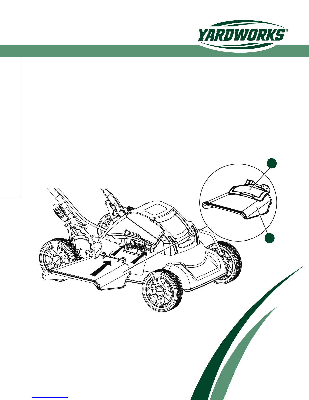
INSTALLING THE SIDE DISCHARGE CHUTE
1. Lift the side discharge cover (1).
2. Align the grooves on the deector (2) with the pins on the underside of the cover.
3. Lower the deector until the hooks on the mower deck are secured in the openings in the
deector.
4. Release the deector and cover.
Assembly
1
2
model no. 060-1721-4 | contact us: 1.866.523.5218
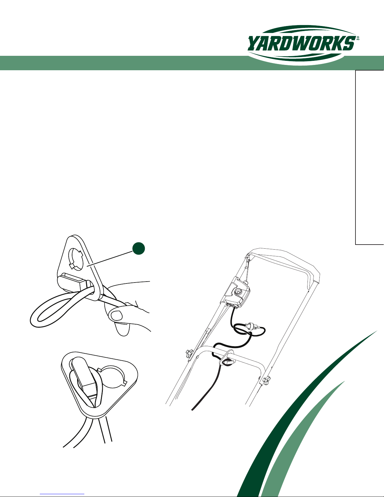
USING THE CORD RETAINER
This lawn mower is equipped with a cord retainer in order to prevent the extension cord from disconnecting from the power cord while the mower is in use. The cord retainer hangs from the cord guide
bar.
NOTE: Do not plug the extension cord into the outlet until it has been connected to the cord retainer
and plugged into the mower.
To use the cord retainer (1):
1. Fold the extension cord in order to forming a tight loop near the retainer.
2. Push the loop through the bottom hole in the retainer.
3. Slide the loop over the retaining clip, and pull down until the cord is secured.
9
1
Assembly

10
model no. 060-1721-4 | contact us: 1.866.523.5218
Some of the following symbols may be used on this product. Please study them and learn their
meaning. Proper interpretation of these symbols will allow you to operate the product better and
safer.
Symbol Name Designation/Explanation
V Volts Voltage.
A Amperes Current.
Hz Hertz Frequency (cycles per second).
W Watts Power.
min Minutes Time.
Symbols
n
o
/min Per Minute Revolutions, strokes, surface speed, orbits etc., per minute.
Alternating Current Type of current.
Direct Current Type or a characteristic of current.
No Load Speed Rational speed, at no load
Class II Construction Double-insulated construction.
Wet Conditions Alert Do not expose to rain or use in damp locations.
Read The Operator’s
Manual
Eye Protection Wear eye protection when operating this equipment.
Ricochet
Sharp Blade Danger – Keep hands and feet away from blade.
Operating on a slope Do not mow a slope that has an angle of greater than 15°.
Keep Bystanders Away Keep all bystanders at least 100’ away.
To reduce the risk of injury, user must read and understand operator’s
manual before using this product.
Thrown objects can ricochet and result in personal
injury or property damage.
SAVE THESE INSTRUCTIONS!

model no. 060-1721-4 | contact us: 1.866.523.5218
GENERAL SAFETY RULES
READ ALL INSTRUCTIONS CAREFULLY
• Carefully read all instructions on the mower and in the manual before attempting to assemble and
operate the mower. Keep this manual in a safe place for future reference, and consult it regularly.
• Become familiar with all controls and their proper operation. Know how to stop the mower and
how to disengage the power in an emergency.
• Do not allow children under the age of 14 to operate this mower. Children who are 14 years of age
and older must read and understand the operating instructions and the safety rules in this manual,
and must be trained and supervised by a parent.
• Do not allow anyone to operate this mower until they have read and understand the instructions.
• In order to avoid contact with the blade or injury caused by a thrown object, stay in the operator’s
zone behind the handles, and keep children and bystanders at least 75’ (20 m) away from the
mower while it is in operation. Stop the motor immediately if someone enters the mowing area.
• Thoroughly inspect the area where the equipment is to be used. Remove all stones, sticks, wire,
bones, toys and other foreign objects that could be tripped over or thrown by the blade. Thrown
objects can cause serious personal injury.
• Plan your mowing pattern in such a way as to avoid discharging material toward roads, sidewalks,
bystanders, etc. Do not discharge material against a wall or obstruction. Doing so may cause the
discharged material to ricochet back toward the operator.
• Always wear proper eye protection in order to protect your eyes while operating or performing any
adjustment or repair. Thrown objects that ricochet can cause serious eye injury.
• Always wear a face mask or a dust mask when operating the mower in a dusty environment.
• Dress properly. Do not wear loose clothing or jewellery that can get caught in moving parts. The
wearing of protective gloves and safety footwear is recommended.
• As an added safety measure, Ground Fault Circuit Interrupter (GFCI) protection should be
provided on the circuit(s) or outlet(s) that will be used to power the lawn mower.
11
Safety Information
WARNING: Use of this mower should be restricted to individuals who have
!
read and understood and will follow the warnings and instructions that are
printed in this manual and on the mower.
WARNING: Basic safety precautions should always be followed
!
when using electric lawn mowers, in order to reduce the risk of re,
electric shock, and personal injury.

12
model no. 060-1721-4 | contact us: 1.866.523.5218
• In order to prevent electric shock, use this mower only with a CSA/CUL listed extension cord that
is approved for outdoor use, such as Type SW–A, SOW–A, STW–A, STOW–A, SJW–A, SJOW–A,
SJTW–A, or SJTOW–A.
• Extension cord: Verify that the extension cord is in good condition, is heavy enough to carry the
current that your mower will draw, and is polarized (one blade of the plug is wider than the other).
A 100’ (30 m) extension cord should be of 14 AWG, a 50’ (15 m) extension cord should be
16 AWG, and a 150’ (45 m) extension cord should be 12 AWG. Undersized cords cause a drop in
the line voltage, which leads to a loss of power and overheating.
• In order to reduce the risk of electric shock, this lawn mower is equipped with a polarized plug
(one blade is wider than the other), and must be used with a polarized extension cord. The lawn
mower’s plug will only t into the polarized extension cord one way. If the plug does not t into the
extension cord properly, reverse the plug. If the plug still does not t, obtain a proper polarized
extension cord. A polarized extension cord must be plugged into a polarized wall outlet. This plug
will only t into the polarized outlet one way. If the plug does not t into the outlet properly, reverse
Safety Information
the plug. If the plug still does not t, contact a qualied electrician to install a proper outlet. Do not
alter the lawn mower’s plug, the receptacle on the extension cord, or the plug on the extension
cord in any way.
• Household circuit: This mower is designed to operate on a 15 A circuit. If the mower has difculty
starting when connected to a circuit that contains a standard 15 A fuse or circuit breaker, call the
toll-free helpline (1-866-523-5218). Do not use a fuse or circuit breaker with higher rating than
that specied for your particular branch circuit.
• Do not abuse the cord by pulling the mower by the cord or yanking on the cord in order to
disconnect it from the outlet. Keep the cord away from heat, oil, and sharp edges.
• Many injuries occur as a result of the mower being pulled over the operator’s foot during a fall
caused by slipping or tripping. Do not operate this mower bare feet, or while wearing sandals
or lightweight (e.g., canvas) shoes. Do not hold on to the mower if you are falling. Release the
handle immediately.
DANGER: This mower was built to be operated according to the rules for safe
!
operation that are contained in this manual. As with any type of power equipment,
carelessness or error on the part of the operator can result in serious injury. This
mower is capable of amputating body parts and throwing objects. Failure to
observe the following safety rules could result in serious injury or death.
WARNING: This symbol indicates important safety instructions. If these
!
instructions are not followed, it could endanger the personal safety
and/or property of the operator and others. Read and understand all
instructions in this manual before attempting to operate the mower.
Failure to comply with these instructions may result in personal injury.

model no. 060-1721-4 | contact us: 1.866.523.5218
• Never pull the mower back toward you while you are walking. If you must back the mower away
from a wall or an obstruction, rst look down and behind in order to avoid tripping, and then follow
these steps:
• Step back from the mower in order to fully extend your arms.
• Be sure that you are well balanced.
• Pull the mower back slowly.
• Repeat these steps as necessary.
• Do not use mower for any job except that for which it is intended. Do not force the mower.
• Do not operate the mower while under the inuence of alcohol or drugs.
• Stay alert: Do not operate the mower when you are tired. Pay attention to what you are doing. Use
common sense.
• Do not put hands or feet near rotating parts or under the cutting deck. Contact with the blade can
amputate hands and feet.
• Do not attempt to adjust the wheels or the cutting height while the motor is running.
• Avoid dangerous environments. Do not operate the mower in the rain or in wet or damp grass.
• Mow only in daylight or in good articial light. Do not rush a mowing job.
• Stop the blade when crossing gravel driveways, walkways, or roads.
• If the mower starts to vibrate abnormally, stop the motor and check for the cause immediately.
Vibration is generally a warning of trouble.
• Stop the motor and wait until the blade comes to a complete stop before removing the grass
catcher or unclogging the chute. The cutting blade will continue to rotate for a few seconds after
the motor is shut off. Do not place any part of your body in the blade area until you are sure that
the blade has stopped rotating.
• Never operate the mower without a proper trail shield, discharge cover, grass catcher, blade/motor
control, or other safety protective devices in place and in working order. Do not operate the mower
with damaged safety devices. Doing so can result in injury.
13
Safety Information

14
model no. 060-1721-4 | contact us: 1.866.523.5218
OPERATING ON A SLOPE
Slopes are a major factor related to accidents involving slips and falls, which can result in severe
injury. Operating the mower on a slope requires extra caution. If you feel uneasy on a slope, do
not mow it. For your safety, use the slope gauge that is included as part of this manual to measure
slopes before operating this mower on a sloped or hilly area. Do not mow a slope that has an angle
greater than 15°.
• Mow across the face of a slope, never up and down. Exercise extreme caution when changing
direction on a slope.
• Watch for holes, ruts, rocks, hidden objects, or bumps that may cause a slip or a trip. Tall grass
can hide obstacles. Remove all objects such as rocks, tree limbs, etc., that can be tripped over
or thrown by the blade.
• Always be sure of your footing. If you feel like you are losing your balance, release the blade/
motor control handle immediately. The blade will stop rotating within 3 seconds.
• Do not mow near drop-offs, ditches, or embankments, because you could lose your footing or
Safety Information
balance.
• Do not mow a slope that has an angle greater than 15°, as determined using the slope gauge.
• Do not mow wet or damp grass. Unstable footing can cause slipping.
CHILDREN
• Tragic accidents can occur if the operator is not aware of the presence of children. Keep children
out of the mowing area and under the watchful care of a responsible adult. Stay alert, and turn
the mower off if a child enters the mowing area. Look behind and down for small children before
and while moving backwards. Use extreme care when approaching blind corners, doorways,
shrubs, trees, or other objects that may obscure your view of a child who may run into the path of
the mower.
• Do not allow children under the age of 14 to operate this mower. Children who are 14 years
of age and older must read and understand the operating instructions and safety rules
in this manual, and must be trained and supervised by a parent.

model no. 060-1721-4 | contact us: 1.866.523.5218
SERVICE
• When servicing the mower, use only replacement parts that are listed in this manual. The use of
parts that do not meet the original equipment specications may lead to improper performance,
and may compromise safety.
• Before cleaning, repairing, or inspecting, verify that the blade and all moving parts have come to
a complete stop. In order to prevent accidental start-ups, disconnect the power cord when the
mower is not in use.
• Follow the instructions for lubricating and changing accessories.
• Inspect the lawn mower's power cord and extension cords regularly, and replace them
immediately if they are damaged. In order to obtain replacement parts, call the toll-free helpline, at
1-866-523-5218.
• Keep the handles dry, clean, and free of oil and grease.
• In order to reduce the risk of re, keep the motor free of grass, leaves, and debris build-up.
• Check the blade and the motor mounting bolts for proper tightness frequently. Visually inspect
blade for damage (e.g., bent, cracked, or worn).
• For best and safest performance, maintain the mower with care. Keep the mower blade sharp
and clean. Mower blades are sharp, and can cut. Wrap the blades or wear gloves, and use extra
caution when servicing.
• Keep all nuts, bolts, and screws tight in order to be sure that the mower is in safe working
condition.
• Do not tamper with safety devices. Check them regularly for proper operation.
• After striking a foreign object, stop the motor and disconnect the power cord. Thoroughly inspect
the mower for any damage. Repair any damage before operating the mower.
• The grass catcher components, discharge cover, and trail shield are subject to wear and damage,
which could expose moving parts or allow objects to be thrown. As a safety precaution, check the
components frequently and immediately replace any parts that show signs of wear, or that are
cracked or broken. Use original equipment manufacturer's (OEM) parts only, as listed in
this manual.
• When it is not in use, store the mower indoors in a dry area, locked up or out of
the reach of children.
15
Safety Information

16
model no. 060-1721-4 | contact us: 1.866.523.5218
DOUBLE-INSULATED LAWN MOWER
Double insulation eliminates the need for the usual three-wire grounded power cord and grounded
power supply system. Wherever there is electric current in the mower, there are two complete sets
of insulation to protect the user. All exposed metal parts are isolated from the internal metal motor
components by protecting insulation.
Safety Information
IMPORTANT: Servicing a lawn mower with double insulation requires extreme
!
care and knowledge of the system, and should only be performed by a qualied
service technician. If repairs are required, call the toll-free helpline, at 1-866-523-
5218. Always use original factory replacement parts when servicing.
WARNING: IT IS YOUR RESPONSIBILITY to restrict the use of this
!
mower to people who have read and understand the warnings and
instructions that appear in this manual and on the mower, and who will
follow them.

model no. 060-1721-4 | contact us: 1.866.523.5218
SLOPE GAUGE
Use this page as a guide in order to identify slopes that cannot be mowed safely.
• DO NOT USE the lawn mower on these slopes.
• SIGHT AND HOLD THIS EDGE LEVEL WITH A VERTICAL TREE.
• FOLD ON THE DOTTED LINE. THIS REPRESENTS A SLOPE OF 15°.
SIGHT AND HOLD THIS LEVEL WITH A VERTICAL TREE
A POWER POLE
A CORNER OF A BUILDING
OR A FENCE POST
17
Safety Information

18
model no. 060-1721-4 | contact us: 1.866.523.5218
STARTING AND STOPPING THE MOWER
STARTING THE MOWER:
• Plug the mower into an approved outdoor extension cord.
• Press and hold the start button (1).
• Pull the bail switch (2) toward the handle to start the mower and release the button.
STOPPING THE MOWER:
Release the bail switch (2).
Operation
1
WARNING: Ensure that other people and pets remain at least 50’ (15 m) away
!
when the mower is in use.
2
WARNING: The operation of any mower can result in foreign objects
!
being thrown into the eyes, which can cause severe eye damage. Always
wear safety glasses while operating the mower and while performing any
adjustments or repairs.

model no. 060-1721-4 | contact us: 1.866.523.5218
ADJUSTING THE CUTTING HEIGHT
When shipped, the wheels on the mower are set to a low cutting position. Before using the
mower for the rst time, raise the cutting position to the height best suited for your lawn. The
average lawn should be between 1 1/2 to 2” (3.8 to 5 cm) during cool months and between 2 and
3 3/4” (5 cm to 8.3 cm) during hot months.
To adjust the blade height:
• To raise the blade height, grasp the height adjustment lever (1) and move it toward the back of the
mower.
• To lower the blade height, grasp the height adjustment lever (1) and move it toward the front of the
mower.
19
HIGH
1
Operation
LOW

20
model no. 060-1721-4 | contact us: 1.866.523.5218
ADJUSTING THE UPPER HANDLE HEIGHT
You may raise or lower the upper handle to a position that is comfortable for you.
1. Loosen the upper handle knob.
2. Move the upper handle to the desired position. There are 2 positions for you to choose from.
3. Tighten the upper handle knob as much as you can.
Operation

model no. 060-1721-4 | contact us: 1.866.523.5218
SLOPE OPERATION
• Mow across the face of slopes, never up and down. Exercise extreme caution when changing
direction on slopes.
• Watch for holes, ruts, rocks, hidden objects or bumps which can cause you to slip or trip. Tall
grass can hide obstacles. Remove all objects such as rocks, tree limbs, etc., which could be
tripped over or thrown by the blade.
• Always be sure of your footing. A slip and fall can cause serious personal injury. If you feel you are
losing your balance, release the power lever immediately.
• Do not mow near drop-offs, ditches, or embankments; you could lose your footing or balance.
21
Operation

22
model no. 060-1721-4 | contact us: 1.866.523.5218
MOWING TIPS
• Make sure the lawn is clear of stones, sticks, wires and other objects that could damage the lawn
mower blade or motor. Do not mow over property stakes or other metal posts. Such objects could
be accidentally thrown by the mower in any direction and cause serious personal injury to the
operator and others.
• For a healthy lawn, always cut off 1/3 or less of the total length of the grass.
• Do not cut wet grass, it will stick to the underside of the deck and prevent proper bagging or
mulching of grass clippings.
• New or thick grass may require a narrower cut or a higher cutting height.
• Clean the underside of the mower deck after each use to remove grass clippings, leaves, dirt and
any other accumulated debris.
• When cutting long grass, reduce walking speed to allow for more effective cutting and a proper
discharge of the clippings.
NOTE: Always stop mower, allow blade to completely stop before cleaning underneath the mower.
Operation
WARNING: Slopes are a major factor related to slip and fall
!
accidents that can result in severe injury. Operation on slopes requires
extra caution. If you feel uneasy on a slope, do not mow it. For your
safety, do not attempt to mow slopes greater than 15°.

model no. 060-1721-4 | contact us: 1.866.523.5218
GENERAL MAINTENANCE
• Before each use, inspect the entire product for damaged, missing or loose parts such as screws,
nuts, bolts, caps, etc.
• Tighten securely all fasteners and caps, and do not operate this product until all missing or damaged parts are replaced. Please call YardWorks tools customer service for assistance. Avoid using
solvents when cleaning plastic parts. Most plastics are susceptible to damage from various types
of commercial solvents and may be damaged by their use. Use clean cloths to remove dirt, dust,
oil, grease, etc.
• Periodically check all nuts and bolts for proper tightness to ensure safe operation of the mower.
• Wipe the mower clean with a dry cloth occasionally. Do not use water.
• The handle may be folded away completely for storage:
• Fully loosen the handle knobs on the sides of the handle and fold the upper handle down.
• Push inward on each side of the lower handle, and lift the sides of the lower handle past the
edges of the handle mounting brackets. Avoid pinching or trapping any cables.
23
Maintenance
WARNING: When servicing, use only authorised replacement parts. Use of any
!
other parts may create a hazard or cause product damage.
WARNING: Do not at any time let brake uids, gasoline,
!
petroleum-based products, penetrating oils, etc., come in contact
with plastic parts. Chemicals can damage, weaken, or destroy
plastic, which may result in serious personal injury.

24
model no. 060-1721-4 | contact us: 1.866.523.5218
LUBRICATION
All of the bearings in this product are lubricated with a sufcient amount of high grade lubricant for the
life of the unit under normal operating conditions. Therefore, no further bearing lubrication is required.
Maintenance
WARNING: Always protect hands by wearing heavy gloves and/or wrapping
!
the cutting edges of the blade with rags and other material when performing
blade maintenance. Contact with the blade could result in serious personal
injury.
WARNING: Do not lubricate any of the wheel components.
!
Lubrication may cause the wheel components to fail during use,
which could result in serious personal injury to the operator and/or
mower, or property damage.

model no. 060-1721-4 | contact us: 1.866.523.5218
REPLACING THE CUTING BLADE
1. RELEASE THE BAIL SWITCH TO TURN THE MOWER OFF, WAIT FOR THE BLADE TO COME TO
A COMPLETE STOP, AND THEN UNPLUG THE POWER CORD.
2. While wearing leather padded gloves, wedge a block of wood between the blade and the mower
deck in order to prevent the blade from turning when the nut is being removed.
3. Using a 15-mm wrench or socket, loosen the blade nut (1) and remove the blade (4). Turn the nut
“COUNTERCLOCKWISE” to loosen it and “CLOCKWISE” to tighten it.
4. Remove the blade nut (1), the square washer (2), the insulator washer (3) and the blade (4).
5. To re-install the blade, position the blade with the cutting edges toward the ground. Assemble
the blade nut, the square washer, and the insulator washer in the exact order in which they were
removed. Using a 15 mm wrench or socket, turn the blade nut CLOCKWISE to secure the blade.
25
4
3
Maintenance
1
2
WARNING: Be sure to replace the parts in the exact order in which
!
they were removed. When installing the cutting blade, verify that it is
installed with the curved ends pointing toward the mower deck, and
not toward the ground. Refer to the schematic drawing above.

26
model no. 060-1721-4 | contact us: 1.866.523.5218
PROBLEM POSSIBLE CAUSE SOLUTION
Motor refuses to
start.
Mower functions
Troubleshooting
intermittently.
Mower leaves
ragged nish and/or
motor labours.
Blade not rotating
while mower is
switched on.
Excessive
vibrations/noise.
Power turned off.
Mains socket faulty.
Extension cable damaged.
Fuse faulty/blown.
Grass too long.
Motor protector has been activated.
Extension cable damaged.
Internal wiring of mower damaged.
Motor protector has been activated.
Cutting height too low.
Cutting blade blunt.
Possible clogging.
Blade tted upside down.
Cutting blade obstructed.
Blade nut/bolt loose.
Blade nut/bolt loose.
Cutting blade damaged.
Turn power on.
Use another socket.
Inspect cable, replace if damaged.
Replace fuse.
Increase cutting height and tilt mower to reduce
starting load.
Allow motor to cool and increase cutting height.
Inspect cable, replace if damaged.
Contact service agent.
Allow motor to cool and increase cutting height.
Increase cutting height.
Replace the blade.
Check underneath the mower and clear out as
necessary (always wear gardening gloves).
Ret blade correctly.
Switch off mower. Clear obstruction (always wear
gardening gloves).
Tighten blade nut/bolt.
Tighten blade nut/bolt.
Replace the blade.

model no. 060-1721-4 | contact us: 1.866.523.5218
27
2-YEAR LIMITED WARRANTY
For TWO YEARS from the date of purchase within
Canada, YARDWORKS® CANADA will, at its
option, repair or replace for the original purchaser,
free or charge, any part or parts that are found to be
defective in material or workmanship.
• 7-day over-the-counter replacement for initial
defects for unused product (RA # required for
used product)
• 2-year repair warranty
This warranty does not cover:
1. Any part that has become inoperative due to
misuse, commercial use, abuse, neglect, accident,
improper maintenance, or alteration;
2. The unit, if it has not been operated and/or
maintained in accordance with the Owner’s
Manual;
3. Normal wear;
4. Routine maintenance items such as lubricants,
blades;
5. Normal deterioration of the exterior finish due to
use or exposure.
the movement of any power equipment unit or
attachment are the responsibility of the purchaser.
The purchaser must pay transportation charges
for any part submitted for replacement under this
warranty, unless such return is requested, in
writing, by YARDWORKS® CANADA.
Other Warranties: All other warranties, whether
express or implied, including any implied warranty
of merchantability, are limited in their duration to that
set forth in this express limited warranty. The
provisions as set forth in this warranty provide the
sole and exclusive remedy of YARDWORKS®
CANADA obligations arising from the sale of its
products.
YARDWORKS® CANADA will not be liable for
incidental or consequential loss or damage.
Imported by YardWorks Canada, Toronto, Canada M4S
2B8
Warranty
How to Obtain Service: Warranty service is available
by calling the Toll-Free Helpline, at 1-866-523-5218.
YARDWORKS® CANADA will not accept the return of
a complete unit unless prior written permission has
been extended by YARDWORKS® CANADA.
Transportation Charges: Transportation charges for
YARDWORKS CANADA will not be liable
for incidental or consequential loss or
damage.

Made in China. Imported by YardWorks
Canada Toronto, Canada M4S 2B8
 Loading...