


model no. 060-1703-8 | contact us: 1.866.523.5218
IMPORTANT:
Read and follow all safety rules and operating
instructions before using this product.
Instruction
Manual
Electric Compact Push Lawn Mower
3084514
Certified to CSA STD.
C22.2 No. 147-15

2
model no. 060-1703-8 | contact us: 1.866.523.5218
Table of Contents
Voltage 120 V ~ 60 Hz
Motor 10 A
Motor Speed 3,300 rpm
Cutting Width 14” (35 cm)
Cutting height adjustment 1–3’’ (2.5–7.5 cm)
Wheel size Front 5 1/2’’ (14 cm)
Rear 8’’ (20 cm)
Weight 30 lb 3 oz (13.7 kg)
SPECIFICATIONS 2
KNOW YOUR MOWER 3
ASSEMBLY 5
OPERATION 9
MAINTENANCE 13
TROUBLE SHOOTING 15
SYMBOLS 16
ELECTRICAL INFORMATION 17
IMPORTANT SAFETY INSTRUCTIONS 19
EXPLODED VIEW 22
PARTS LIST 23
WARRANTY 24
Specifications
ELECTRIC LAWN MOWER

3
Know Your Mower
3
16
9
1
4
7
22
21
12a
12b
21a
10
13
11
8
14
2
5
18
20
19
17
13a
6

model no. 060-1703-8 | contact us: 1.866.523.5218
4
model no. 060-1703-8 | contact us: 1.866.523.5218
Know Your Mower
Item Description
1
Handle
2 Lock-off button
3 Start lever
4 Upper handle
5 Lawnmower housing
6 Cord strain relief
7 Lower handle
8 Deflector guard
9 Carry handle
10 Lever for height adjustment
11 Wheel
12 a Butterfly nuts
b Wing nuts
c Washer (See pg 8)
13 Grass catcher
a handle
b frame (See pg 6)
c clamping sleeve (See pg 6)
d hook (See pg 6)
e support (See pg 6)
f flap (See pg 14)
14
Cord clip
15
Screws (See pg 8)
16
Power cord with plug
17
Air vents
18
Spindle
19
Cutting blade
20
Bolt
21
Mulching insert
a unlock button
22
Rear discharge chute

5
Part List
UNPACKING
This product requires assembly.
• Carefully remove the product and any accessories from the box. Make sure that all
items listed in the packing list are included.
• Inspect the product carefully to make sure no breakage or damage occurred during
shipping.
• Do not discard the packing material until you have carefully inspected and
satisfactorily operated the product.
• If any parts are damaged or missing, please call customer service for assistance.
ITEMS NOT SUPPLIED
Screwdriver
Cross-head screwdriver
Suitable personal protective equipment
PACKING LIST
Mower
Instruction Manual
!
WARNING: Do not use this product if any parts on
the packing list are already attached to your product
when you unpack it. Parts on this list are not attached
to the product by the manufacturer and require
customer installation. Use of a product that may have
been improperly assembled could result in serious
personal injury.
Assembly
6
model no. 060-1703-8 | contact us: 1.866.523.5218
Assembly
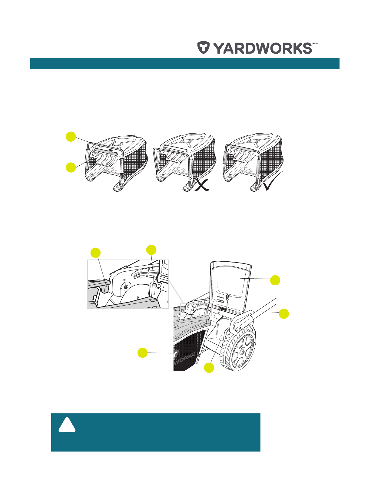
GRASS CATCHER
• Pull the clamping sleeve up (13c) and lock it onto the frame (13b) (Fig. 1). Ensure the
side clamping sleeves are properly fixed on the frame.
• Open the deflector guard (8) and hold it in position.
• Align the supports (13e) with the hooks (13d) to hang the grass catcher (13) onto the
lawn mower (Fig. 2).
!
Note: Check if the mulching insert (21) is already
inserted into the discharge chute (22). Remove the
mulching insert (21) prior to attaching the grass
catcher (13) if necessary.
Fig. 1
Fig. 2
13b
13d
13c
13e
13
7
8
22

7
HANDLE
• A cord restraint system helps keep the extension cord connection secure during mower
operation.
• Ensure the cord strain relief (6) is positioned over the middle of lower handle (7) (Fig. 3).
• Slightly spread the ends of the lower handle (7) and place them on the threaded bolts
on the right and left of the housing (Fig. 4). Fasten the handle using the butterfly nuts
(12a) to tighten (Fig. 4).
Assembly
Fig. 4
Fig. 3
7
5
7
7
!
NOTE: When both wing nuts are loosened, the curved
handle can be folded down for storing the equipment.
Ensure that the power cable is not caught.
12a
6

model no. 060-1703-8 | contact us: 1.866.523.5218
8
model no. 060-1703-8 | contact us: 1.866.523.5218
Ensure that the power cord (16) is properly fixed with the cord clips (14) to the handle.
Connect to the power supply.
!
WARNING: For your safety, the handle must be in
cutting position before connecting the plug to socket!
!
WARNING: Do not connect to power supply until the
assembly is complete. Failure to comply could result in
accidental starting and possible serious personal injury.
• Double the extension cord back, about 16” (40 cm) from the end. Lead the loop
through the cord strain relief (6) and hang the loop over the hook. Gently pull on the
cord to ensure that it is fastened (Fig. 7).
Assembly
Fig. 7
6
4
Fig. 5 Fig. 6
7
12b
15
12c
• Fix the upper handle (4) using the enclosed screws (15) and the wing nuts (12b) on the
lower handle (7) (Fig. 5). There are two possible positions.
• Secure the cord (16) with the cord clips (14) (Fig. 6).
6
14

9
Operation
GENERAL OPERATION
Check the product, its power cord and plug as well as accessories for damage before
each use. Do not use the product if it is damaged or shows wear.
• Double check that the blade is properly fixed.
• Always hold the product by its handles. Keep the handles dry to ensure safe support.
• Ensure that the air vents are always unobstructed and clear. Clean them if necessary
with a soft brush. Blocked air vents may lead to overheating and damage the
product.
• Switch the product off immediately if you are disturbed while working by other people
entering the working area. Always let the product come to a complete stop before
removing the grass collection box.
• Do not overwork yourself. Take regular breaks to ensure you can concentrate on the
work and have full control over the product.
CUTTING HEIGHT ADJUSTMENT
Adjust the cutting height according to the needs of your lawn. The cutting height
depends on the kind of lawn and its actual height. When mowing high grass, start with
the maximum cutting height and make a second cut with lower cutting height.
• Push the lever for height adjustment (10) towards the product (step 1) and move it to
the desired cutting height (Fig. 9, step 2).
• Release the lever (10) (Fig. 9, step 3) and ensure it locks into place properly.
ON/OFF SWITCH
• Press on the lock-off button (2) to unlock the start lever (3).
• Then operate the start lever (3) to switch the mower on (Fig. 8).
Fig. 8
2
3

10
model no. 060-1703-8 | contact us: 1.866.523.5218
Step 2
Step 3
Step 1
Operation
Fig. 9
10
!
NOTE: There are 6 cutting height levels available. The
adjustable heights are 25 mm / 35 mm / 45 mm / 55 mm /
65 mm / 75 mm.
GRASS CATCHER
Always attach the grass catcher (13) when using the product for grass collection.
Always carry the grass catcher by its handle.
Indicator
The grass catcher (13) is equipped with a flap (13f) that indicates the filling volume
during operation.
• When the flap (13f) is opened (during operation), the grass catcher (13) has efficient
volume left to collect grass (Fig. 10).
• When the flap (13f) is closed (during operation), the grass catcher (13) is full and
must be emptied (Fig. 11).
Fig. 11Fig. 10
Full positionEmpty position
13
13f

11
Operation
EMPTYING
• Empty the grass catcher (13) frequently during use. Do not wait until it is completely
full. We recommend emptying it when it is half full.
• Put the upper handle bar (4) into the parking position.
• Lift the deflector guard (8) up and hold it in place.
• Lift the grass catcher (13) off the supports (13e).
• Remove the grass clippings from the discharge chute (22) into the grass catcher (13).
Use a proper tool such as a brush.
• Empty the grass clippings onto a compost heap.
• Re-fit the grass catcher (13) to the supports (13e).
When using the product without the grass catcher, insert the mulching insert (21).
Switch the motor off and wait until the blade has come to a complete stop before
removing the grass catcher!
MULCHING INSERT
For mulching work use the mulching insert (21).
• Put the upper handle bar into the parking position.
• Open the deflector guard (8) and hold it in position.
• Remove the grass catcher (13) if necessary.
• Insert the mulching insert (21) into the rear discharge chute (22) (Fig. 12).
Ensure the unlock button (21a) snaps into place.
• Press the unlock button (21a) to release and remove the mulching insert (21) (Fig.
13).
!
WARNING! Do not attempt to use the product without
the grass catcher attached when collecting grass–
danger of flying objects! When using the product
without the grass catcher, insert the mulching insert
(21). Switch the motor off and wait until the blade has
come to a complete stop before removing the grass
catcher!
Fig. 13Fig. 12
21
8
21a

model no. 060-1703-8 | contact us: 1.866.523.5218
12
model no. 060-1703-8 | contact us: 1.866.523.5218
Operation
AFTER USE
• Switch the product off and let it cool down.
• Check, clean and store the product as described below.
!
WARNING: If the product strikes a foreign object, stop
the engine. Switch the product off, disconnect it from
the power supply and let it cool down. Inspect the
product thoroughly for damage. Have any damage
repaired before restarting. Extensive vibration of the
product during operation is an indication of damage.
!
WARNING: For your safety, it is required that the plug
attached to the lawn mower is always connected to an
extension cord. The extension cord must be suitable
for outdoor use with sockets protected against water
splashing. The extension cord must always be used
with the cord restraint system (16).
1
2
3
4
MOWING
• Make sure the lawn is clear of stones, sticks, wires, and other objects that could
damage the lawn mower blades or motor. Such objects could be accidentally thrown
by the mower in any direction and cause serious personal injury to the operator and
others.
• To reduce the possibility of disconnecting the lawn mower from the extension cord,
ensure that the cord restraint system is used.
• For a healthy plot of grass, only cut off one-third or less of the total length of the
grass.
• When cutting heavy grass, reduce walking speed to allow for more effective cutting
and a proper discharge of the clippings.
• Do not cut wet grass. It will stick to the underside of the deck and prevent proper
mulching of grass clippings.
• New or thick grass may require a narrower cut.
• Clean the underside of the mower deck after each use to remove grass clippings,
leaves, dirt, and any other accumulated debris.

13
!
WARNING: Before inspecting, cleaning or servicing
the machine, unplug the power cord and wait for
all moving parts to stop. Failure to follow these
instructions can result in serious personal injury or
property damage.
Maintenance
THE GOLDEN RULES FOR CARE
• Keep the product clean. Remove debris from it after each use and before storage.
• Regular and proper cleaning will help ensure safe use and prolong the life of the
product.
• Inspect the product before each use for worn and damaged parts. Do not operate it if
you find broken or worn parts.
GENERAL CLEANING
• Clean the product with a dry cloth. Use a brush for areas that are hard to reach.
• Remove stubborn dust with compressed air (max. 3 bar).
• Check for any damage and wear. Repair damage in accordance with this instruction
manual or take it to an authorized service centre before using the product again.
• Keep the underbody and blade clean and free of debris.
• All nuts and bolts must be checked periodically for tightness before operation. After
prolonged use, especially in sandy soil conditions, the blade device will become
worn and lose some of the original shape. Cutting efficiency will be reduced and the
blade should be replaced.
• Keep the blade sharp to ensure good cutting performance. Replace a worn or
damaged blade with a new one of the same type or have it sharpened by a qualified
specialist.
• Undo the fastening bolt.
• Remove the blade and replace with a new one.
• When fitting the blade, make sure it is installed in the right direction. The blade’s air
vanes must point toward the motor compartment.
• Then retighten the fastening bolt. The tightening torque should be approximately 18
ft-lb (25 Nm).
STORAGE
• Clean the product as described above.
• Store the product and its accessories in a dry, frost-free place.
• Always store the product in a place that is inaccessible to children. The ideal storage
temperature is between 10 and 30°C.
• We recommend using the original package for storage or covering the product with a
suitable cloth to protect it against dust.

model no. 060-1703-8 | contact us: 1.866.523.5218
14
model no. 060-1703-8 | contact us: 1.866.523.5218
NOTE: Make certain all parts are replaced in the exact
order in which they were removed.
NOTE: Only use identical replacement blades.
NOTE: Only use YARDWORKS replacement parts.
YARDWORKS mower blade replacement part # 0601703-8.
Maintenance
REPLACING THE CUTTING BLADE FIGS. 14 AND 15
• Stop the motor and disconnect the power supply. Allow the blade to come to a
complete stop.
• Turn the mower on its side.
• Wedge a block of wood between the blade and the mower deck in order to prevent the
blade from turning when the nut is being removed (Fig. 14).
• Loosen the blade nut using a 14 mm wrench or socket (not provided) (Fig. 14).
• Remove the blade nut, and blade.
• Make certain the fan assembly is pushed completely against the motor shaft.
• Place the new blade on the shaft against the fan assembly. Make sure it is installed
with the curved ends pointing up toward the mower deck and not down toward the
ground.
• Thread the blade nut on the shaft and finger tighten.
• Torque the blade nut down using a torque wrench (not provided) to ensure the bolt is
properly tightened.
WOOD BLOCK
BLADE
BLADE NUT
Fig. 15Fig. 14
!
!
!

15
Troubleshooting
PROBLEM CAUSE SOLUTION
1. Mower does
not start.
Power is off.
Check the socket, cord and plug
and have any repairs carried out
by an electrician.
Defective on/off switch.
Repair by authorized service
centre.
Worn carbon brushes.
Defective motor.
Grass too long.
Set a higher cutting height. Lift the
front wheels slightly by pressing
down on the handle.
2. Motor stops. Blockage by foreign object Remove the foreign object.
3. Result
unsatisfactory
or motor labours.
Cut height too low. Set a higher cutting height.
Blade blunt.
Have the blade sharpened or
replace it.
Blade area blocked. Clean the equipment.
Blade installed incorrectly . Install the blade correctly.
4. Blade fails to
turn
Blade blocked by grass. Remove the grass.
Blade nut loose. Tighten the blade nut.
5. Strange noises,
rattling or
vibrations.
Blade screw loose. Tighten the blade screw.
Blade damaged. Replace the blade.
6.Motor runs but
blade fails to turn.
Belt drive broken.
Repair by authorized service
centre.

16
model no. 060-1703-8 | contact us: 1.866.523.5218
Some of the following symbols may be used on this product. Please study them and
learn their meaning. Proper interpretation of these symbols will allow you to operate the
product effectively and safely.
Symbol Name
Designation/
Explanation
V Volts Voltage
A Amperes Current
Hz Hertz
Frequency (cycles
per second)
W Watts Power
hrs Hours Time
Alternating
Current
Type of current
Class II
Construction
Double-insulated
construction
Read the
Operator’s
Manual
To reduce the
risk of injury, user
must read and
understand the
operator’s manual
before using this
product.
Eye and
Hearing
Protection
Wear eye and
hearing protection
when operating this
equipment.
Safety Alert
Precautions that
involve your safety.
Do not mow
up and down
slopes.
To avoid a risk
of injury do not
mow up and down
slopes. Always
mow across
slopes.
( Angle ≤15°)
Symbol Name
Designation/
Explanation
Keep all
persons and
pets at a
safe distance
from the
mower while
operating.
To avoid the risk of
injury to bystanders
keep all
persons and pets
at a safe distance
from the
mower while
operating.
Keep hands
and feet clear
of mower deck
and discharge
opening at all
times.
Rotating blades
can cause serious
injury. Keep hands
and feet clear of
mower deck and
discharge opening
at all times.
Always be sure
blade has stopped
after releasing
switch lever
and unplugging
before removing
and replacing
grass catcher,
cleaning, servicing,
transporting or
lifting the mower.
Stay behind
the handle
when the motor
is running.
Objects struck
by mower blade
can cause serious
injury. Stay behind
the handle when
the motor is
running. Always
ensure persons
and pets are clear
of the discharge
from the mower
while operating.
Symbols
Keep hand and feet away.

17
DOUBLE INSULATION
Double insulation is a concept in safety in electric power tools that eliminates the need
for the usual three-wire grounded power cord. All exposed metal parts are isolated from
the internal metal motor components with protecting insulation. Double-insulated tools
do not need to be grounded.
ELECTRICAL CONNECTION
This product has a precision-built electric motor. It should be connected to a power
supply that is 120 V, AC only (normal household current), 60 Hz. Do not operate
this product on direct current (DC). A substantial voltage drop will cause a loss of power
and the motor will overheat. If your product does not operate when plugged into an
outlet, double-check the power supply.
GROUND FAULT CIRCUIT INTERRUPTER
Ground Fault Circuit Interrupter (GFCI) protection should be provided on the circuit(s)
or outlet(s) to be used for the product. Receptacles are available having built-in GFCI
protection and may be used for this measure of safety.
GUIDELINES FOR USING EXTENSION CORDS
USE THE PROPER EXTENSION CORD. Make sure your extension cord is in good
condition. When using an extension cord, be sure to use one heavy enough to carry the
current your product will draw. An undersized cord will cause overheating. The table
below shows the correct size to use depending on cord length and nameplate ampere
rating. If in doubt, use the next heavier gauge. The smaller the gauge number, the
heavier the cord.
!
NOTE: Servicing of a product with double insulation
requires extreme care and knowledge of the system
and should be performed only by a qualified service
technician. For service, we suggest you return the tool
to your nearest authorized service centre for repair.
Always demand that original factory replacement
parts be used when servicing.
Electrical Information
!
WARNING: The double-insulated system is intended
to protect the user from shocks resulting from a break
in the tool’s internal insulation. Observe all normal
safety precautions to avoid electric shocks.

18
model no. 060-1703-8 | contact us: 1.866.523.5218
Minimum Gauge for Extension Cords (AWG)
(when using 120 V only)
Ampere Rating Total Length of Cord in Feet (metres)
More Than Not More Than 25' (7.6 m) 50' (15 m) 100' (30.4 m) 150' (45.7 m)
0 6 18 16 16 14
6 10 18 16 14 12
10 12 16 16 14 12
12 16 14 12 Not Recommended
When using a power tool at a considerable distance from a power source, be sure to use
an extension cord that has the capacity to handle the current the product will draw.
An undersized cord will cause a drop in line voltage, resulting in overheating and loss of
power. Use the chart to determine the minimum wire size required in an extension cord.
Only round jacketed cords listed by Underwriters Laboratories (UL) should be used.
When working outdoors with a product, use an extension cord that is designed for
outside use. This type of cord is designated with “WA” on the cord’s jacket.
Before using any extension cord, inspect it for loose or exposed wires and cut or worn
insulation. It is possible to tie the extension cord and power cord in a knot to prevent
them from becoming disconnected during use. Make knot as shown above, then connect
the plug end of the power cord into the receptacle end of the extension cord. This method
can also be used to tie two extension cords together.
!
WARNING: Although this tool is double insulated, the
extension cord and receptacle must still be grounded
while in use to protect the operator from electric
shocks.
!
WARNING: Check the extension cord before each
use. If damaged, replace immediately. Never use the
product with a damaged cord. Touching the damaged
area could cause electric shocks, resulting in serious
injury.
Electrical Information

19
Important Safety Instructions
READ ALL INSTRUCTIONS
• This cutting machine is capable of
severing hands and feet and throwing
objects. Failure to observe all safety
instructions could result in serious
injury or death.
• Do not use the lawn mower in damp or
wet conditions or operate in the rain.
• Never allow adults to operate the
product without proper instruction.
• Keep the area clear of all bystanders,
children, and pets while mowing. Stop
the machine if anyone enters the area.
• Tragic accidents can occur if the
operator is not alert to the presence of
children. Children are often attracted to
the machine and the mowing activity.
Never assume that children will remain
where you last saw them.
• Keep children out of the mowing
area and under the watchful care of
a responsible adult other than the
operator.
• Be alert and turn the mower off if a
child enters the area.
• Never allow children to operate the
machine.
• Use extra care when approaching blind
corners, shrubs, trees, or other objects
that may block your view of a child.
• Do not wear loose clothing or jewellery.
They can be caught in moving parts.
Use of rubber gloves and footwear is
recommended when working outdoors.
• Keep firm footing and balance. Do not
overreach. Overreaching can result in
loss of balance.
• Do not operate the equipment while
barefoot or when wearing sandals
or similar lightweight footwear. Wear
protective footwear that will protect
your feet and improve your footing on
slippery surfaces.
• Do not leave the mower unattended
while it is running.
• Keep hands and feet away from the
cutting area.
• Operate the lawn mower only in
daylight or good artificial light.
• Always wear safety glasses with side
shields. Everyday glasses have only
impact resistant lenses. They are NOT
safety glasses. Following this rule will
reduce the risk of eye injury. Use face
mask if conditions are dusty.
• Wear safety glasses or goggles that
are marked to comply with ANSI Z87.1
standard when operating this product.
• Use the right appliance. Do not use the
lawn mower for any job except that for
which it is intended.
• Do not force the lawn mower. It will do
the job better and safer at the rate for
which it was designed.
• Stay alert, watch what you are
doing, and use common sense when
operating the lawn mower. Do not
operate the mower while tired or under
the influence of drugs, alcohol, or
medication. A moment of inattention
while operating the lawn mower may
result in serious personal injury.
• Keep the machine in good working
condition. Keep blades sharp and
guards in place and in working order.
• Check all nuts, bolts, and screws at
frequent intervals for proper tightness
to be sure the equipment is in safe
working condition.
• Stop the motor and wait until the blade
comes to a complete stop before
cleaning the lawn mower, removing
the grass catcher, or unclogging the
discharge guard.
• When not in use, the mower should
be stored indoors in a dry, locked-up
place—out of the reach of children.

20
model no. 060-1703-8 | contact us: 1.866.523.5218
• To reduce the risk of electric shocks,
this product has a polarized plug (one
blade is wider than the other) and will
require the use of a polarized extension
cord. The plug will fit into a polarized
extension cord only one way. If the
plug does not fit fully into the extension
cord, reverse the plug. If the plug still
does not fit, obtain a correct polarized
extension cord. A polarized extension
cord will require the use of a polarized
wall outlet. This plug will fit into the
polarized wall outlet only one way. If
the plug does not fit fully into the wall
outlet, reverse the plug. If the plug
still does not fit, contact a qualified
electrician to install the proper wall
outlet. Do not change the equipment
plug, extension cord receptacle, or
extension cord plug in any way.
• Do not abuse the cord. Never use
the cord to pull the lawn mower or to
disconnect the plug from an outlet.
Keep cord away from heat, oil, sharp
edges, or moving parts. Replace
damaged cords immediately. Damaged
cords increase the risk of electric
shocks.
• Make sure your extension cord is
in good condition. When using an
extension cord, be sure to use one
heavy enough to carry the current your
product will draw. A wire gauge size
(A.W.G.) of at least 14 is recommended
for an extension cord 50’ (15 m) or less
feet or less in length. If in doubt, use
the next heavier gauge. The smaller
the gauge number, the heavier the
cord. An undersized cord will cause a
drop in line voltage resulting in loss of
power and overheating.
• WARNING: Use outdoor extension
cords marked SW-A, SOW-A, STW-A,
STOW-A, SJW-A, SJT-A, SJTW-A,
or SJTOW-A. These cords are rated
for outdoor use and reduce the risk of
electric shocks.
• Ground Fault Circuit Interrupter (GFCI)
protection should be provided on the
circuit(s) or outlet(s) to be used for the
lawn mower. Receptacles are available
having built-in GFCI protection and may
be used for this measure of safety.
• Inspect extension cords periodically
and replace if damaged. Keep handles
dry, clean, and free of oil or grease.
SPECIFIC SAFETY RULES
• Do not operate the mower without the
entire grass catcher, discharge guard,
rear guard, or other safety protective
devices in place and working.
• Follow the manufacturer’s instructions
for proper operation and installation
of accessories. Only use accessories
approved by the manufacturer.
• Clear the work area before each use.
Remove all objects such as rocks,
sticks, wire, bones, toys, or other
objects which can be thrown by the
blade. Stay behind the handle when the
motor is running.
• Avoid holes, ruts, bumps, rocks, or
other hidden objects. Uneven terrain
could cause a slip-and-fall accident.
• Do not mow near drop-offs, ditches, or
embankments.
• Mow across the face of slopes, never
up and down. Exercise extreme caution
when changing direction on slopes.
• Plan your mowing pattern to avoid
discharge of material toward roads,
sidewalks, bystanders, and the like.
• Do not mow on wet grass or
excessively steep slopes. Poor footing
could cause a slip-and-fall accident.
Walk, never run.
• Use extra care when approaching blind
corners, shrubs, trees, or other objects
that may block your view.
Important Safety Instructions

21
• Do not pull the mower backward
unless absolutely necessary. If you
must back the mower away from a
wall or obstruction, first look down and
behind to avoid tripping.
• Never direct discharged material
toward anyone. Avoid discharging
material against a wall or obstruction.
Material may ricochet back toward the
operator.
• Stop the blade when crossing gravel
surfaces.
• Objects struck by the lawn mower
blade can cause severe injuries to
persons. The lawn should always be
carefully examined and cleared of all
objects prior to each mowing.
• If the lawn mower strikes a foreign
object, follow these steps:
• Stop the lawn mower and release the
switch lever.
• Disconnect the power cord.
• Thoroughly inspect the mower for
any damage.
• Repair any damage before restarting
and continuing to operate the mower.
• Stop the motor, disconnect the power
cord, and wait until the blade comes to
a complete stop before removing the
grass catcher or unclogging the chute.
The cutting blade continues to rotate
for a few seconds after the motor is
shut off. Never place any part of the
body in the blade area until you are
sure the blade has stopped rotating.
• Disconnect the plug from the power
source before making any adjustments,
changing accessories, or storing the
lawn mower. Such preventive safety
measures reduce the risk of starting
the product accidentally.
• If the mower should start to vibrate
abnormally, stop the motor and check
immediately for the cause. Vibration is
generally a warning of trouble.
• Service on the product must be
performed by qualified repair personnel
only. Service or maintenance
performed by unqualified personnel
could result in injury to the user or
damage to the product.
• Use only identical replacement parts
when servicing the product. Use of
unauthorized parts may create a risk of
serious injury to the user, or damage to
the product.
• If the power supply cord is damaged,
it must be replaced only by the
manufacturer or by an authorized
service centre to avoid risks.
• To reduce the risk of injury, inspect
the catcher assembly frequently
and replace with recommended
replacement if there are signs of wear
or deterioration.
• Save these instructions. Refer to them
frequently and use them to instruct
others who may use this product. If you
loan someone this product, loan them
these instructions also.
Important Safety Instructions
!
WARNING: This machine is capable of inflicting
serious injuries if not used properly. Before you
begin working with the machine, read the operating
instructions carefully and familiarize yourself with
the controls and the proper use of the machine. Keep
these instructions in a safe place where you will
always be able to refer to this information.

22
model no. 060-1703-8 | contact us: 1.866.523.5218
YARDWORKS CANADA will not be liable for incidental
or consequential loss or damage.
Exploded View

23
Parts List
Item Part No. Description QTY
1
111033101 Motor housing 1
2 111030102 Motor assembly 1
2.1 111014103 Drive belt 1
3 111033102 Lower handle twist-lock knob assemby 2
4 111033103 Cable clamp 1
5 111033104 Rear wheel assembly (200 mm) 2
5.1 111005107 Rear wheel axle cap 2
5.2 111030107 Rear wheel (200 mm) 2
6 111033105 Deck assembly 1
7 111033106 Front wheel (140 mm) 2
7.1 111005107 Front wheel axle cap 2
7.2 111013108 Front wheel (140 mm) 2
8 111033107 Front axle assembly 1
9 111033108 Front axle bracket assembly 1
10 111030112 Ballast assembly 1
11 111030113 Blade assembly 1
11.1 111030114 Blade 1
11.2 111001121 M8*20 / M8x20 blade bolt 1
12 111007133 Height adjustment spring assembly 1
13 111033109 Rear axle bracket assembly 1
14 111033110 Rear axle assembly 1
15 111014111 Height connecting rod 1
15.1
111014112 Height adjustment handle 1
16
111030131 Safety flap assembly 1
17
111030122 Mulch plug 1
18
111033111 Upper handle cam lock assembly 2
19
111030129 Lower handle 1
20
111005128 Cord retainer 1
21
111033112 Upper handle assembly with switch box 1
21.1
111033113 Switch box assembly 1
21.2
111030126 Upper handle assembly 1
21.3
111033114 Handle bracket assembly 1
22
111001111 Cable clips 2
23
111033115 Rear safety door 1
24
111033116 Complete Redi-Bag assembly 1

24
model no. 060-1703-8 | contact us: 1.866.523.5218
Warranty
WARRANTY
For TWO YEARS from the date of
purchase within Canada, YARDWORKS
CANADA will, at its option, repair or
replace for the original purchaser, free
of charge, any part or parts found to be
defective in material or workmanship.
This warranty does not cover:
• Any part that has become inoperative
due to misuse, commercial use,
abuse, neglect, accident, improper
maintenance, or alteration; or
• The unit, if it has not been operated
and/or maintained in accordance with
the owner’s manual; or
• Normal wear, except as noted below;
• Routine maintenance items such as
lubricants, blade sharpening;
• Normal deterioration of the exterior
finish due to use or exposure.
Full One Hundred Twenty Days Warranty
on Normal Wear Parts: Normal wear
parts are defined as blade adaptors,
blades, grass bags and tires. These parts
are warranted to the original purchaser
to be free from defects in material and
workmanship for a period of one hundred
twenty (120) days from the date of retail
purchase.
How to Obtain Service: Warranty service
is available by calling the toll-free helpline,
at 1.866.523.5218. The factory will not
accept the return of a complete unit
unless prior written permission has been
extended by YARDWORKS CANADA.
Transportation Charges: Transportation
charges for the movement of any power
equipment unit or attachment are the
responsibility of the purchaser. The
purchaser must pay transportation
charges for any part submitted for
replacement under this warranty unless
such return is requested in writing by
YARDWORKS CANADA.
Other Warranties: All other warranties,
express or implied, including any implied
warranty of merchantability is limited in
its duration to that set forth in this express
limited warranty. The provisions as set
forth in this warranty provide the sole
and exclusive remedy of YARDWORKS
CANADA obligations arising from the sale
of its products.

Made in China. Imported by Yardworks Canada.
Toronto, Canada M4S 2B8
 Loading...