

Portable Generator
model number 055-0362-8 | contact us: 1.866.523.5218
IMPORTANT:
Read and follow all safety rules and operating
instructions before using this product.
Instruction
Manual

2
model no. 055-0362-8 | contact us: 1.866.523.5218
SPECIFICATIONS 3
KNOW YOUR GENERATOR 4
ASSEMBLY 6
OPERATION 9
SAFETY AND MAINTENANCE 14
EXPLODED VIEW PRODUCT 22
PARTS LIST PRODUCT 23
EXPLODED VIEW ENGINE 28
PARTS LIST ENGINE 29
WIRING DIAGRAM 34
TROUBLESHOOTING 35
Table of Contents
WARRANTY 36

Starting Watts 7200
Running Watts 6000
AC Voltage 120/240 V
Phase Single
Frequency 60 Hz
Fuel Capacity 9 gal (34 L)
Gross Weight 219 lb 13 oz (99.7 kg)
Net Weight 200 lb 3 oz (90.8 kg)
Length 29 1/8” (74 cm)
Width 27 9/16” (70 cm)
Height 26 11/16” (67.8 cm)
Oil Capacity 1.2 qt (1.1 L)
Battery Size 12 V, 15 Ah
Engine Size 439 cc
FUEL
Fuel capacity is 9 gal (34 L). Use regular unleaded gasoline with a minimum octane
rating of 87 and an ethanol content of less than 10% by volume.
3
Specifications
MAINTENANCE VALVE CLEARANCE
Intake: 0.005–0.007” (0.13–0.17 mm)
Exhaust: 0.007–0.009” (0.17–0.22 mm)
SPARK PLUGS
OEM spark plug: NHSP F6RTC
Replacement spark plug: NGK BPR6ES or equivalent
Make certain the spark plug gap is 0.028–0.031” (0.7–0.8 mm).
OIL
Use 10W-30 automotive oil.
Oil capacity is up to 1.2 qt (1.1 L).
DO NOT OVERFILL.
Please reference the following chart for
recommended oil types for use in the
generator.
Degrees Celsius
Full Synthetic 5W-30
Degrees Fahrenheit
(Outside)
(Outside)
4
model no. 055-0362-8 | contact us: 1.866.523.5218
1
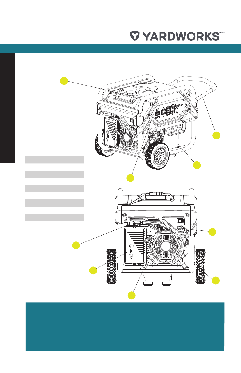
Know Your Generator
1. Fuel Tank
2. Power Panel
3. Battery
4. Fold-away Handle
5. Fuel Valve
6. Never-flat Wheels
7. Recoil Starter
8. Air Filter
9. Choke
2
4
3
5
9
8
6
7
KNOW YOUR GENERATOR
Before attempting to assemble or operate your generator, please become familiar with
the major parts and components.
• Know where to refuel the generator.
• Know where and how to turn the fuel supply off and on.
• Know where and how to start the generator manually in the event the battery is dead.
5
1
43 5 6 7 8
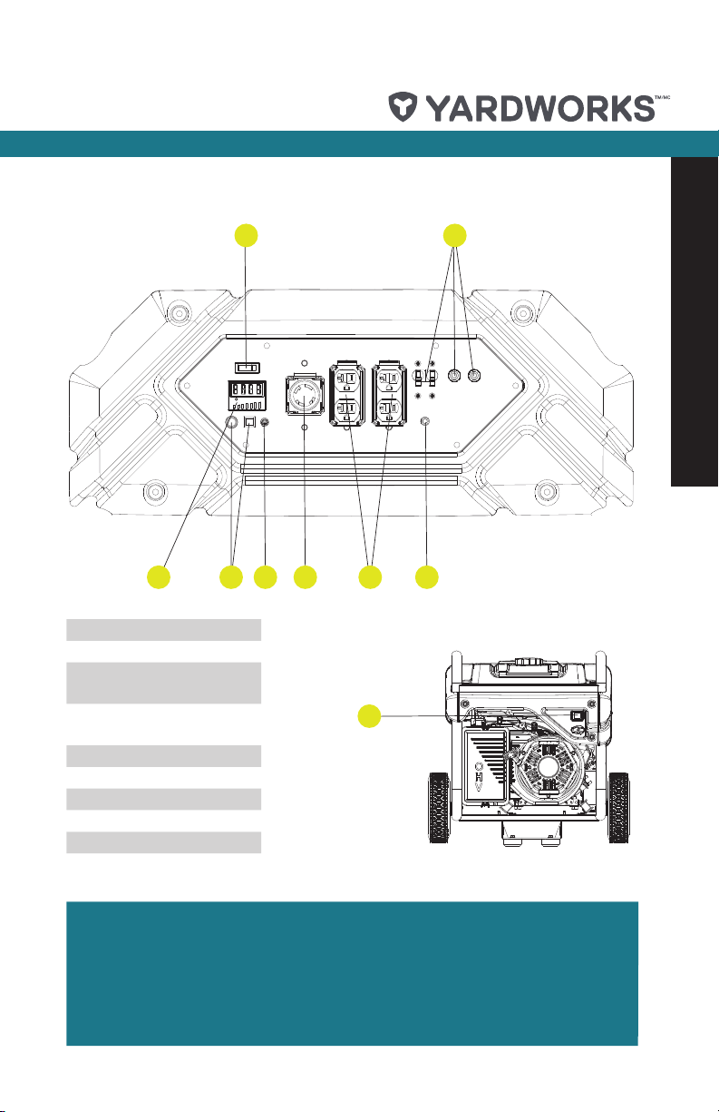
1. Battery Switch
2. Circuit Breakers
3. Power Meter and Fuel
Life Meter
4. Remote Reset Light
and Button
5. 12 V Charger Outlet
6. L14-30R Outlet
7. 5-20R Duplex (2)
8. Ground
9. Engine Switch
2
Know Your Generator
9
KNOW YOUR GENERATOR
Familiarize yourself with the power panel outlets and switches before operation.
• Know how the circuit breakers work and how to reset them if tripped.
• Know where and how to turn the engine off and on.
• Know where and how to plug items into the correct outlets.
6
model no. 055-0362-8 | contact us: 1.866.523.5218
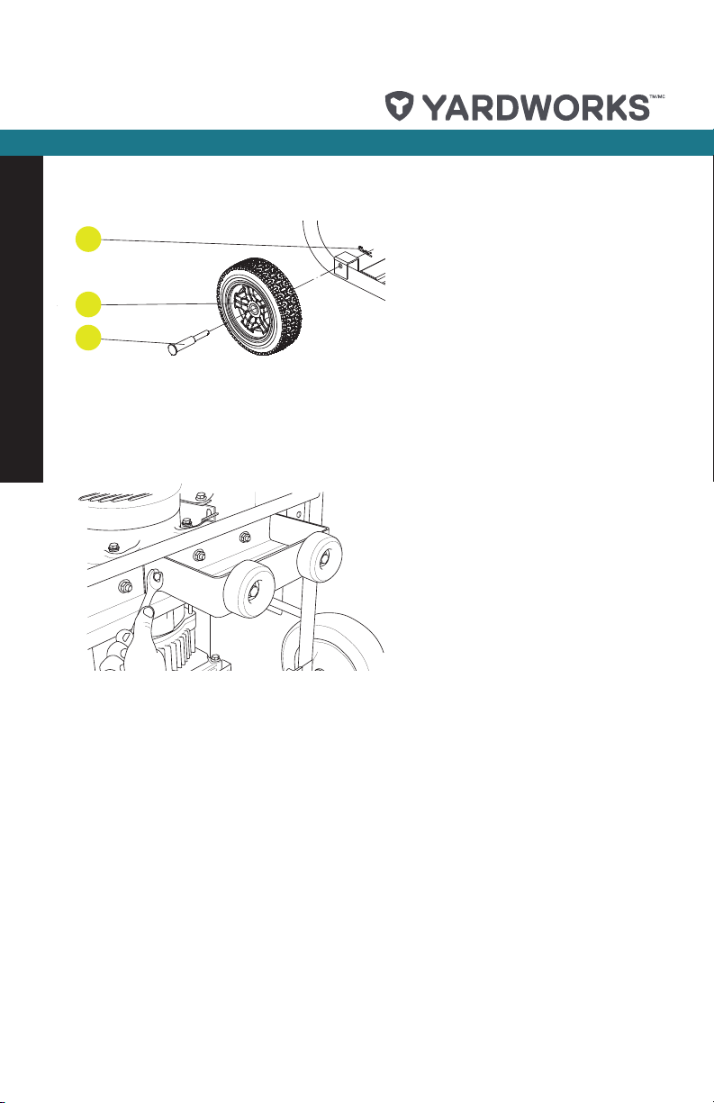
INSTALL THE WHEEL KIT
1. Before adding fuel and oil, tip the
generator on its side.
2. Slide the wheel pin roll (#84) through
the wheel (#83) from the outside.
3. Slide the pin roll through the mount
point on the frame.
4. Secure the R-Pin (#85).
5. Repeat steps 2–4 to attach the
second wheel.
63
64
85
83
84
Assembly
INSTALL THE SUPPORT LEG
1. Attach the support leg to the
generator frame with flange bolts
(M8 x 16) and flange lock nuts (M8).
2. Tip the generator slowly so that it
rests on the wheels and support leg.
CONNECTING THE BATTERY
1. Remove the protective cover from the
red (+) lead on the battery.
2. Attach the red (+) lead to the red
(+) terminal on the battery with the
flange bolt (M5 x 10) and secure with
the flange nut (M5).
3. Repeat steps 1–2 for the black (–)
battery lead.

ADD ENGINE OIL
The recommended oil type is 10W-30 automotive oil.
1. Place the generator on a flat, level surface.
2. Remove oil fill cap/dipstick to add oil.
3. Add up to 1.2 qt (1.1 L) of oil and replace oil fill cap/dipstick. DO NOT OVERFILL.
4. Check engine oil level daily and add as needed.
Once oil has been added, a visual check should show oil about 1–2 threads from running
out of the fill hole.
If using the dipstick to check oil level, DO NOT screw in the dipstick while checking.
The engine is equipped with a low oil shut-off and will stop when the oil level in the
crankcase falls below the threshold level.
We consider the first 5 hours of run time to be the break-in period for the unit. During
the break–in period stay at or below 50% of the running watt rating and vary the load
occasionally to allow stator windings to heat and cool. Adjusting the load will also cause
engine speed to vary and help seat piston rings. After the 5 hour break-in period, change
the oil.
7
Assembly
Weather will affect engine oil and engine performance. Change the type of engine oil used
based on weather conditions to suit the engine needs.
Synthetic oil may be used after the 5 hour initial break-in period. Using synthetic oil
does not increase the recommended oil change interval.
Degrees Celsius
Degrees Fahrenheit
WARNING: DO NOT attempt to crank or start the engine
!
before it has been properly filled with the recommended
type and amount of oil. Damage to the generator as a result
of failure to follow these instructions will void your warranty.
IMPORTANT: The generator rotor has a sealed, pre-
!
lubricated ball bearing that requires no additional
lubrication for the life of the bearing.
(Outside)
Full Synthetic 5W-30
(Outside)

8
model no. 055-0362-8 | contact us: 1.866.523.5218
ADD FUEL
Use clean, fresh, regular unleaded fuel with a minimum octane rating of 87 and an ethanol
content of less than 10% by volume.
DO NOT mix oil with fuel.
Clean the area around the fuel cap.
Remove the fuel cap.
Slowly add fuel to the tank. DO NOT OVERFILL. Fuel can expand after filling. A minimum of
1/4” (6.4 mm) of space left in the tank is required for fuel expansion, more than
1/4” (6.4 mm) is recommended. Fuel can be forced out of the tank as a result of expansion if it
is overfilled, and can affect the stable running condition of the product. When filling the tank, it
is recommended to leave enough space for the fuel to expand.
Screw on the fuel cap and wipe away any spilled fuel.
Assembly
DO NOT pump gas directly into the generator at the gas station. Use an approved container
to transfer the fuel to the generator.
DO NOT fill fuel tank indoors.
DO NOT fill fuel tank when the engine is running or hot.
DO NOT overfill the fuel tank.
DO NOT light cigarettes or smoke when filling the fuel tank.
Pouring fuel too fast through the fuel screen may result in blow back of fuel at the operator
while filling.
GROUNDING
Your generator must be properly connected to an appropriate ground to help prevent
electric shock.
A ground terminal connected to the frame of the generator has been provided on the
power panel. For remote grounding, connect of a length of heavy gauge (12 AWG
minimum) copper wire between the generator ground terminal and a copper rod driven
into the ground. We strongly recommend that you consult with a qualified electrician to
ensure compliance with local electrical codes.
The generator system ground connects the frame to the ground terminals on the power
panel.
Electrical devices that require a grounded receptacle pin connection will not function if
the receptacle ground pin is not functional.
Failure to properly ground the generator can result in electric shock.

GENERATOR LOCATION
NEVER operate the generator inside any building including garages, basements,
crawlspaces, sheds, enclosure or compartment, including the generator compartment of a
recreational vehicle. Please consult your local authority. In some areas, generators must
be registered with the local utility. Generators used at construction sites may be subject to
additional rules and regulations. Generators should be on a flat, level surface at all times
(even while not in operation). Generators must have at least 5’ (1.5 m) of clearance from
all combustible material. In addition to clearance from all combustible material, generators
must also have at least 3’ (91.4 cm) of clearance on all sides to allow for adequate cooling,
maintenance and servicing. Generators should never be started or operated in the back of
a SUV, camper, trailer, in the bed of a truck (regular, flat or otherwise), under staircases/
stairwells, next to walls or buildings, or in any other location that will not allow for adequate
cooling of the generator and/or the muffler. DO NOT contain generators during operation.
Allow generators to properly cool before transport or storage.
• Place the generator in a well-ventilated area. DO NOT place the generator near vents or
intakes where exhaust fumes could be drawn into occupied or confined spaces. Carefully
consider wind and air currents when positioning generator.
• Do not operate or store the generator in rain, snow, or wet weather.
• Using a generator or electrical appliance in wet conditions, such as rain or snow, near a
pool or sprinkler system, or when your hands are wet, could result in electrocution.
• During operation the muffler and exhaust fumes produced will become hot. If adequate
cooling and breathing space are not supplied, or if the generator is blocked or contained,
temperatures can become extremely heated and may lead to fire.
9
Operation
WARNING: Failure to follow proper safety precautions may
!
void manufacturer’s warranty.
SURGE PROTECTION
Electronic devices, including computers and many programmable appliances use
components that are designed to operate within a narrow voltage range and may be affected
by momentary voltage fluctuations. While there is no way to prevent voltage fluctuations, you
can take steps to protect sensitive electronic equipment.
• Install UL1449, CSA-listed, plug-in surge suppressors on the outlets feeding your
sensitive equipment.
• Surge suppressors come in single- or multi-outlet styles. They’re designed to protect
against virtually all short-duration voltage fluctuations.
• Voltage fluctuation may impair the proper functioning of sensitive electronic equipment.

10
model no. 055-0362-8 | contact us: 1.866.523.5218
WIRELESS REMOTE
Wireless remote starting is only possible within 78’ (24 m) of the generator.
Do not attempt to adjust the carburetor choke. The remote system will automatically close
and open the choke.
1. Make certain the generator is on a flat, level surface.
2. Turn off all electrical loads connected to the generator. Never start or stop the generator
with electrical devices plugged in and turned on.
3. Turn the fuel valve to the “ON” position.
4. Press the battery switch to “ON”.
5. Press the engine switch to “ON”.
• WIRELESS REMOTE START: press and release the “START” button on the handheld
remote control device. DO NOT hold the button down, only press the button once. The
Operation
engine will attempt to start six times.
A safety feature is provided which delays the electrical power availability during starting
mode. The delay lasts for approximately 15 seconds. The delay is provided to prevent
damage to the generator if electrical loads are inadvertently turned on during engine startup.
When the battery switch is in the “ON” position, the switch will light up if the battery is
sending out a charge. If the switch does not light up while in the “ON” position, check that the
battery connection is still good.
NOTE: The supplied 12 V, 9 Ah battery does re-charge
!
while the engine is running, but it is also recommended that
the battery be fully charged at least once per month.
ELECTRIC START AND RECOIL START
1. Make certain the generator is on a flat, level surface.
2. Turn off all electrical loads connected to the generator. Never start or stop the generator
with electrical devices plugged in and turned on.
3. Turn the fuel valve to the “ON” position.
4. Press the ignition switch to “ON”.
5. Move the choke lever to the “CHOKE” position.
• ELECTRIC START: Press the battery switch to “ON.” Press and hold the ignition
switch to the “START” position. Release as the engine begins to roll over. If the engine
fails to start within five seconds, release the switch and wait at least ten seconds before
attempting to start the engine again.
• RECOIL START: Pull the starter cord slowly until resistance is felt and then pull
rapidly.
6. Do not over-choke. As as soon as engine starts, move the choke lever to the “RUN”
position.
Keep choke lever in “CHOKE” position for only 1 push cycle of the ignition button or 1 pull
of the recoil starter. After first pull, move choke lever to the “RUN” position for up to the
next 3 pulls of the recoil starter. Too much choke leads to spark plug fouling/engine flooding
due to the lack of incoming air. This will cause the engine not to start.
If the engine starts but does not continue to run make certain that the generator is on a flat,
level surface. The engine is equipped with a low oil sensor that will prevent the engine from
running when the oil level falls below a critical threshold.

CONNECTING ELECTRICAL LOADS
Let the engine stabilize and warm up for a few minutes after starting.
Plug in and turn on the desired 120 or 240 V AC single phase, 60 Hz electrical loads.
DO NOT connect 3-phase loads to the generator.
DO NOT connect 50 Hz loads to the generator.
DO NOT overload the generator.
Connecting a generator to your electric utility company’s power lines or to another power
source may be against the law. In addition this action, if done incorrectly, could damage your
generator and appliances and could cause serious injury or even death to you or a utility
worker who may be working on nearby power lines. If you plan to run a portable electric
generator during an outage, please notify your electric utility company immediately and
remember to plug your appliances directly into the generator. Do not plug the generator
into any electric outlet in your home. Doing so could create a connection to the utility
company power lines. You are responsible for ensuring that your generator’s electricity does
not feed back into the electric utility power lines. If the generator will be connected to a
building electrical system, consult your local utility company or a qualified electrician.
Connections must isolate generator power from utility power and must comply with all
applicable laws and codes.
DO NOT OVERLOAD GENERATOR
Capacity
Follow these simple steps to calculate the running and starting watts necessary for your
purposes.
1. Select the electrical devices you plan on running at the same time.
2. Total the running watts of these items. This is the amount of power you need to keep
your items running.
3. Identify the highest starting wattage of all devices identified in step 1. Add this
number to the number calculated in step 2. Surge wattage is the extra burst of power
needed to start some electric driven equipment. Following the steps listed under
“Power Management” will guarantee that only one device will be starting at a time.
Power Management
Use the following formula to convert voltage and amperage to watts:
Volts x Amps = Watts
To prolong the life of your generator and attached devices, follow these steps to add electrical
load:
1. Start the generator with no electrical load attached
2. Allow the engine to run for several minutes to stabilize.
3. Plug in and turn on the first item. It is best to attach the item with the largest load first.
4. Allow the engine to stabilize.
5. Plug in and turn on the next item.
6. Allow the engine to stabilize.
7. Repeat steps 5-6 for each additional item.
11
Operation
IMPORTANT: Never exceed the specified capacity when
!
adding loads to the generator.

12
model no. 055-0362-8 | contact us: 1.866.523.5218
POWER METER AND FUEL LIFE METER
The power and fuel life meter are located on the front of the operator’s panel and shown
as Item #3 on page 5.
The meter is divided into two separate displays. The LCD display on top shows the
voltage [U], frequency [H], running time [R], total time, and remaining fuel run time [F].
Each parameter is shown for several seconds and then automatically cycles through in
the order listed.
The LED display on bottom shows the output power being producing based on the
electrical load connected to the generator. As the output increases, more LED lights are
shown until the generator is overloaded at which time a red LED light will appear. DO
NOT OVERLOAD GENERATOR – see page 11. The LED display also shows the time the
generator will run based on the current output power and the remaining fuel level. As the
fuel decreases, fewer lights are shown until there is approximately 10% fuel remaining
Operation
at which time an orange light will appear. This indicates that the fuel tank needs to be
refilled shortly or will run out. The output power will be displayed at all times except when
the remaining fuel run time is shown on the LCD at which time the remaining fuel run time
is displayed on the LED.
STOPPING THE ENGINE
1. Turn off and unplug all electrical loads. Never start or stop the generator with electrical
devices plugged in or turned on.
2. Let the generator run at no-load for several minutes to stabilize internal temperatures
of the engine and generator.
3. Turn the fuel valve to the “OFF” position.
4. Let the engine run until fuel starvation has stopped the engine. This usually takes a few
minutes.
5. Press the engine switch to the “OFF” position.
6. Press the battery switch to the “OFF” position.
Important: Always ensure that the fuel valve and the engine switch are in the “OFF”
position when the engine is not in use.
NOTE: If the engine will not be used for a period of two (2)
!
weeks or longer, please see the Storage section for proper
engine and fuel storage.

OPERATION AT HIGH ALTITUDE
The density of air at high altitude is lower than at sea level. Engine power is reduced
as the air mass and air-fuel ratio decrease. Engine power and generator output will be
reduced approximately 3½% for every 1000 feet of elevation above sea level. This is a
natural trend and cannot be changed by adjusting the engine. At high altitudes increased
exhaust emissions can also result due to the increased enrichment of the air fuel ratio.
Other high altitude issues can include hard starting, increased fuel consumption and
spark plug fouling.
To alleviate high altitude issues other than the natural power loss, a high altitude
carburetor main jet and installation instructions can be obtained by contacting Yardworks
Canada 1-866-523-5218.
The part number and recommended minimum altitude for the application of the high
altitude carburetor main jet is listed in the table below.
In order to select the correct high altitude main jet it is necessary to identify the carburetor
model. For this purpose, a code is stamped on the side of the carburetor. Select the
correct main jet part number corresponding to the carburetor code found on your
particular carburetor.
13
Operation
Carburetor
Code
P28-3-Z
P28-3-H
P28-3-Y
!
Main Jet Part Number Altitude
Standard 47. 13 101 7.2 1. Z
Altitude 47.131017.21. 01.Z
Standard 47. 13 101 7.2 1. H
Altitude 47.131017.21. 01.H
Standard 47. 13 101 7.2 1.Y
Altitude 47.131017.21. 01.Y
WARNING: Operation using the alternative main jet at
elevations lower than the recommended minimum altitude
can damage the engine. For operation at lower elevations,
the standard main jet must be used. Operating the engine
with the wrong engine configuration at a given altitude
may increase its emissions and decrease fuel efficiency
and performance.
5500 Feet
(1676 Meters)

14
model no. 055-0362-8 | contact us: 1.866.523.5218
IMPORTANT SAFETY INFORMATION
Read this manual thoroughly before
operating your generator. Failure to
follow instructions could result in
serious injury or death.
Generator exhaust contains carbon
monoxide: a colourless, odourless, poison
gas. Breathing carbon monoxide will cause
nausea, dizziness, fainting or death. If you
start to feel dizzy or weak, get to fresh air
immediately.
Operate generator outdoors only in a well-
ventilated area.
DO NOT operate the generator inside any
Safety and Maintenance
building including garages, basements,
crawlspaces, sheds, enclosure or
compartment, including the generator
compartment of a recreational vehicle.
DO NOT allow exhaust fumes to enter a
confined area through windows, doors,
vents or other openings.
DANGER CARBON MONOXIDE: using
a generator indoors CAN KILL YOU IN
MINUTES.
Rotating parts can entangle hands, feet,
hair, clothing and/or accessories.
Traumatic amputation or severe laceration
can result.
Keep hands and feet away from rotating
parts.
Tie up long hair and remove jewellery.
Operate equipment with guards in place.
DO NOT wear loose-fitting clothing,
dangling drawstrings or items that could
become caught.
Generator produces powerful voltage.
DO NOT touch bare wires or receptacles.
DO NOT use electrical cords that are worn,
damaged or frayed.
DO NOT operate generator in wet weather.
DO NOT allow children or unqualified
persons to operate or service the generator.
Use a ground fault circuit interrupter (GFCI)
in damp areas and areas containing
conductive material such as metal decking.
Use approved transfer equipment to isolate
generator from your electric utility and notify
your utility company before connecting your
generator to your power system.
Sparks can result in fire or electrical shock.
WHEN SERVICING THE GENERATOR:
Disconnect the spark plug wire and place it
where it cannot contact the plug.
DO NOT check for spark with the plug
removed.
Use only approved spark plug testers.
Running engines produce heat. Severe
burns can occur on contact.
Combustible material can catch fire on
contact.
DO NOT touch hot surfaces.
Avoid contact with hot exhaust gases.
Allow equipment to cool before touching.
Maintain at least 3’ (91.4 cm) of clearance
on all sides to ensure adequate cooling.
Maintain at least 5’ (1.5 m) of clearance
from combustible materials.
Rapid retraction of the starter cord will pull
hand and arm towards the engine faster
than you can let go.
Unintentional startup can result in
entanglement, traumatic amputation or
laceration.
Broken bones, fractures, bruises or sprains
could result.
Exceeding the generator’s running capacity
can damage the generator and/or electrical
devices connected to it.
DO NOT overload the generator.
Start the generator and allow the engine to
stabilize before connecting electrical loads.
Connect electrical equipment in the
off position, and then turn them on for
operation.
Turn electrical equipment off and
disconnect before stopping the generator.
DO NOT tamper with the governed speed.
DO NOT modify the generator in any way.
Improper treatment or use of the generator
can damage it, shorten its life and void your
warranty.
Use the generator only for intended uses.
Operate only on level surfaces.
DO NOT expose generator to excessive
moisture, dust, or dirt.
DO NOT allow any material to block the
cooling slots.
If connected devices overheat, turn them off
and disconnect them from the generator.

15
DO NOT USE THE GENERATOR IF:
• Electrical output is lost.
• Equipment sparks, smokes or emits
flames.
• Equipment vibrates excessively.
• Operation of this equipment may create
sparks that can start fires around dry
vegetation.
• A spark arrestor may be required. The
operator should contact local fire agencies
for laws or regulations relating to fire
prevention requirements.
MEDICAL AND LIFE SUPPORT USES:
• In case of emergency, call 911
immediately.
• NEVER use this product to power life
support devices or life support appliances.
• NEVER use this product to power medical
devices or medical appliances.
• Inform your electricity provider immediately
if you or anyone in your household
depends on electrical equipment to live.
• Inform your electrical provider immediately
if a loss of power would cause you or
anyone in your household to experience a
medical emergency.
• Fuel and fuel vapours are highly
flammable and extremely explosive.
• Fire or explosion can cause severe burns
or death.
• Unintentional startup can result in
entanglement, traumatic amputation or
laceration.
WHEN ADDING OR REMOVING FUEL:
• Turn the generator off and let it cool for
at least two minutes before removing the
fuel cap. Loosen the cap slowly to relieve
pressure in the tank.
• Only fill or drain fuel outdoors in a wellventilated area.
• DO NOT pump gas directly into the
generator at the gas station. Use an
approved container to transfer the fuel to
the generator.
• DO NOT overfill the fuel tank.
• Always keep fuel away from sparks, open
flames, pilot lights, heat and other sources
of ignition.
• DO NOT light or smoke cigarettes.
WHEN STARTING THE GENERATOR:
• DO NOT attempt to start a damaged
generator.
• Make certain that the gas cap, air filter,
spark plug, fuel lines and exhaust system
are properly in place.
• Allow spilled fuel to evaporate fully before
attempting to start the engine.
• Make certain that the generator is resting
firmly on level ground.
WHEN OPERATING THE GENERATOR:
• DO NOT move or tip the generator during
operation.
• DO NOT tip the generator or allow fuel or
oil to spill.
WHEN TRANSPORTING OR
SERVICING THE GENERATOR:
• Make certain that the fuel shutoff valve is in
the off position and the fuel tank is empty.
• Disconnect the spark plug wire.
When storing the generator:
• Store away from sparks, open flames, pilot
lights, heat and other sources of ignition.
This device complies with Industry
Canada licence–exempt RSS standard(s).
Operation is subject to the following
two conditions: (1) this device may not
cause interference, and (2) this device
must accept any interference, including
interference that may cause undesired
operation of the device.
Safety and Maintenance

16
model no. 055-0362-8 | contact us: 1.866.523.5218
STORAGE AND MAINTENANCE
The owner/operator is responsible for all periodic maintenance.
Tampering with the factory set governor will void your warranty.
Improper maintenance will void your warranty.
Maintenance, replacement, or repair of emission control devices and systems may be
performed by any non-road engine repair establishment or individual.
The owner/operator is responsible for all periodic maintenance.
Complete all scheduled maintenance in a timely manner. Correct any issue before
operating the generator.
ENGINE MAINTENANCE
To prevent accidental starting, remove and ground spark plug wire before performing any
service.
Safety and Maintenance
Oil
Change oil when the engine is warm. Refer to the oil specification to select the proper grade
of oil for your operating environment.
1. Remove the oil drain plug with a 15 mm socket and extension (not included).
2. Allow the oil to drain completely.
3. Replace the drain plug.
4. Remove oil fill cap/dipstick to add oil.
5. Add 1.2 qt (1.1 L) of oil and replace oil fill cap/dipstick. DO NOT OVERFILL.
6. Dispose of used oil at an approved waste management facility.
Once oil has been added, a visual check should show oil about 1-2 threads from running out
of the fill hole.
If using the dipstick to check oil level, DO NOT screw in the dipstick while checking
Spark Plugs
1. Remove the spark plug cable from the spark plug.
2. Use a spark socket (not included) to remove the plug.
3. Inspect the electrode on the plug. It must be clean and not worn to produce the spark
required for ignition.
4. Make certain the spark plug gap is 0.028–0.031” (0.7–0.8 mm).
5. Refer to the spark plug recommendation section of specifications when replacing the plug.
6. Carefully thread the plug into the engine.
7. Use a spark plug socket (not included) to firmly install the plug.
8. Attach the spark plug wire to the plug.

Air Filter
1. Remove the snap-on cover holding the air filter to the assembly.
2. Remove the foam element.
3. Wash in liquid detergent and water. Squeeze thoroughly dry in a clean cloth.
4. Saturate in clean engine oil.
5. Squeeze in a clean, absorbent cloth to remove all excess oil.
6. Place the filter in the assembly.
7. Reattach the air filter cover and snap in place.
Spark Arrester
Allow the engine to cool completely before servicing the spark arrester.
1. Remove the three (3) screws holding the cover plate which retains the end of the spark
arrester to the muffler.
2. Remove the spark arrester screen.
3. Carefully remove the carbon deposits from the spark arrester screen with a wire brush.
4. Replace the spark arrester if it is damaged.
5. Position the spark arrester in the muffler and attach with the three (3) screws.
Failure to clean the spark arrester will result in degraded engine performance.
17
Safety and Maintenance
Cleaning
Use a damp cloth to clean exterior surfaces of the engine.
Use a soft bristle brush to remove dirt and oil.
Use an air compressor (25 PSI) to clear dirt and debris from the engine.
DO NOT spray engine with water. Water can contaminate the fuel system.
Adjustments
The air-fuel mixture is not adjustable. Tampering with the governor can damage your
generator and your electrical devices and will void your warranty.

18
model no. 055-0362-8 | contact us: 1.866.523.5218
Maintenance Schedule
Follow the service intervals indicated in the following maintenance schedule.
Service your generator more frequently when operating in adverse conditions.
Every 8 hours or daily
Check oil level
Clean around air intake and muffler
First 5 hours
Change oil
Every 50 hours or every season
Clean air filter
Safety and Maintenance
Change oil if operating under heavy load or in hot environments
Every 100 hours or every season
Change oil
Clean/adjust spark plug
Check/adjust valve clearance*
Clean spark arrester
Clean fuel tank and filter*
Every 250 hours
Clean combustion chamber*
Every 3 years
Replace fuel line
*To be performed by knowledgeable, experienced owners or certified dealers.

Generator Maintenance
1. Make certain that the generator is kept clean and stored properly. Only operate the unit
on
a flat, level surface in a clean, dry operating environment. DO NOT expose the unit to
extreme conditions, excessive dust, dirt, moisture or corrosive vapours.
2. Use a damp cloth to clean exterior surfaces of the generator.
3. Use a soft bristle brush to remove dirt and oil.
4. Use an air compressor (25 PSI) to clear dirt and debris from the generator.
5. Inspect all air vents and cooling slots to ensure that they are clean and unobstructed.
6. DO NOT use a garden hose to clean the generator.
Water can enter the generator through the cooling slots and damage the generator
windings.
Storage
The generator should be started at least once every 14 days and allowed to run for at least
20 minutes. For longer term storage, please follow these guidelines.
Generator Storage
1. Add a properly formulated fuel stabilizer to the tank.
2. Be sure all appliances are disconnected from the generator.
3. Run the generator for a few minutes so the treated fuel cycles through the fuel system
and carburetor.
4. Turn the fuel valve to the “Off” position.
5. Let the generator run until fuel starvation has stopped the engine. This usually takes a
few minutes.
6. The generator needs to cool completely before cleaning and storage.
7. Clean the generator according to the maintenance section.
8. Change the oil.
9. Remove the spark plug and pour about 1/2 oz (14.8 mL) of oil into the cylinder. Crank
the engine slowly to distribute the oil and lubricate the cylinder.
10. Reattach the spark plug.
11. Store the unit in a clean, dry place out of direct sunlight.
19
Safety and Maintenance
Generator exhaust contains odourless and colourless carbon monoxide gas.
To avoid accidental or unintended ignition of your remote start generator during periods of
storage, the following precautions should be followed:
•When storing the generator for short periods of time make sure that the ignition switch, the
fuel valve and the battery switch are set in the OFF position.
• When storing the generator for extended periods of time make sure that the Ignition
switch, the fuel valve and the battery switch are set in the the the OFF position and the
battery leads have been disconnected from the battery.

20
model no. 055-0362-8 | contact us: 1.866.523.5218
Generator Battery
This product is equipped with an automatic battery charging circuit. The battery will
receive charging voltage when the engine is running. The battery will maintain a proper
charge if the unit is used on a regular basis (about once every two weeks). If it is used
less frequently, the battery should be connected to a trickle charger (not included) or
battery maintainer (not included) to keep the battery properly charged. If the battery is not
able to start the engine, it can be started by manually pulling the engine recoil cord. If the
battery voltage is extremely low, the charging circuit may not be able to re-charge the
battery. In this case, the battery must be connected to a standard automotive style battery
charger for re-charging before it can be used.
Disconnect the Battery
1. Remove the protective cover from the black/negative battery lead.
2. Disconnect the black/negative lead from the black/negative terminal on the battery and
Safety and Maintenance
store the cap screw (M5 x 10) and nut (M5).
Repeat steps 1–2 for the red/positive battery lead.
Store the battery in a cool, dry place.
Charge the Battery
For a generator equipped with batteries for electric starting, proper battery maintenance
and storage should be followed. An automatic battery charger (included) with automatic
trickle charging capability should be used to charge the battery. Maximum charging rate
should not exceed 1.5 amps. Follow the instructions included with the battery charger.
The battery should be fully charged at least once per month.
A float charger will maintain the battery condition over long storage periods.

This Page Intentionally Left Blank.
21
Safety and Maintenance

22
model no. 055-0362-8 | contact us: 1.866.523.5218
3258
31
29
30
33
22
59
Exploded View (Product)
28
11
12
131415
10
8
6 7 9
2
3
5
4
1
68
66
16
26 27
25
24
23
17
22
21
20
18
19
65
67
66
61
62
64
60
63
62
4041
39
38
37
36
35
34
51
52
53
54
55
56
57
44
46
47
48
49
50
12 5
12 6
12 8 12 9
434445
12 7
12 4
12 2 1 23
12 1
12 0
11 9
11 1
11 31 14
65
64
13 0
19
85
83
69
70
66
71
757677
78
79
66
72
73
74
82 8 3 84
81
80
868788
66
99
98
97
10 0
10 1
10 2
52
91
89
92
90
9394
11 2
10 3
10 5
10 71 08
10 6
10 91 10 59 11 5 11 6 11 7 1 18
10 4
95
96 42

Item Description Drawing QTY
1 Fuel Filter Assembly 122.070300.04 1
2 Fuel Tank Cap 122.070100.07 1
3 Cover Plate, Teal 3145c 152.070016.00.99 1
4 Screw/Washer Assembly M4 x 14, Black 1.9074.4.0414.1 3
5 Decorative Plate, Fuel Tank 152.070008.00 1
6 Screw M5 x 13 2.08.068.2 5
7 Fuel Level Sensor, 165 mm 152.070035.00 1
8 Seal Ring 122.070036.00 1
9 Pipe, Reversal Valve, 670 mm 122.070014.02 1
10 Hole, Breather Tube 24.070030.00 1
11 Reversal Valve 24.070800.00 1
12 Flange Bolt M6 x 20 1.5789.0620.2 2
13 Lock Washer Ø6 1.93.06 4
14 Flat Washer, Ø24 x Ø6.5 x 1.5 2.03.004 2
15 Mount Vibration, Fuel Tank 122.070015.01 2
16 Fuel Tank, 33.9L, Cool Gray 11c 152.071000.46.29 1
17 Mount Vibration, Fuel Tank, EL 152.070024.01 2
18 Fitting, Fuel Tank 21.070600.03 1
19 Clamp Ø8.7 x b8 2.06.016 4
20 Fuel Pipe 152.070011.14 1
21 Holder, Air Cleaner 45.090006.20 1
22 Lock Nut M6, Flange 1.6177.1.06 2
23 Washer Ø8 1.848.08 2
24 Lock Washer Ø8 1.93.08 2
25 Nut M8 1.6175.08 2
26 Gasket, Exhaust 46.100001.07 1
27 Muffler Assembly, Black 419c 46.101000.01.30 1
28 Screw/Washer Assembly M5 x 10 1.9074.4.0510 3
29 Spark Arrester Assembly 46.101300.00 1
30 Flange Bolt M8 x 20 1.16674.0820 1
31 Bush Ø9 x Ø13 x 16 2.13.009 1
32 Flange Bolt M8 x 35 1.16674.0835 1
33 Nut M5 1.6175.05 2
34 Washer Ø5 1.97.1.05 2
23
Parts List (Product)

24
model no. 055-0362-8 | contact us: 1.866.523.5218
Item Description Drawing QTY
35 Lock Washer Ø5 1.93.05 2
36 Bolt M5 x 214 2.08.035 2
37 Carbon Brush Assembly 152.190300.00 1
38 Pinch, Carbon Brush 122.190004.01 1
39 Bolt/Washer Assembly M5 x 20 1.9074.15.0520 1
40 Flange Bolt M5 x 12 1.16674.0512.2 2
41 End Cover, Generator, Teal 3145c 152.190003.00.99 1
42 Screw/Washer Assembly M5 x 16 1.9074.17.0516 2
43 Terminal Block 122.190400.00 1
Parts List (Product)
44 Flange Bolt M5 x 16 1.16674.0516 3
45 AVR 154.190200.02 1
46 End Housing 152.190002.00 1
47 Flange Bolt/Washer Assembly M6 x 179 2.08.032 4
48 Cover, Stator 152.191002.00 1
49 Flange Bolt/Washer Assembly M10 x 265 2.08.034 1
50
51
52 Flange Bolt M6 x 8 1.5789.0608 2
53 Air Guide 152.192300.01 1
54 Plug A, Fore-Cover 152.190005.00 1
55 Plug B, Fore-Cover 152.190005.01 1
56 Engine, 439cc, Teal 3145c 47.602.99 1
57 Grounding Line 150 mm 5.1900.029 1
58 Flange Bolt M6 x 12 1.5789.0612 1
59 Toothed Lock Washer Ø6 1.862.06 2
60 Cover, Handle, Black 419c 152.200702.02.30 1
61 Handle, U Shape, Black 419c 152.200701.05.30 1
62 Short Pin, Handle 152.200703.02 2
63 "R" Shape 11.110008.00 2
64 Circlip Ø8 1.894.1.08 2
65 Long Pin, Handle 152.200703.03 2
66 Flange Bolt M6 x 15, Black 1.5789.0615.1 14
Stator Assembly, Al, 140 x 190 mm,
THD<15%
Rotor Assembly, Al, 140 x 190 mm,
THD<15%
152.191200.33 1
152.191100.33 1

Item Description Drawing QTY
67 Decorative Plate, Left, Cool Gray 11c 152.200800.11.29 1
68 Decorative Plate, Back, Cool Gray 11c 152.200800.13.29 1
69 Fuel Pipe 152.070011.13 1
70 Clip Ø12.5 x 7 2.05.009 2
71 Decorative Plate, Right, Cool Gray 11c 152.200800.12.29 1
72 Ignition Switch, Red 5.1000.001.3 1
73 Screw M4 x 10 1.823.0410 1
74 Knob 122.070001.00 1
75 Fuel Valve 83.070400.01 1
76 Screw ST4.2 x 19 1.845.4219 2
77 Frame, 700 x 541 x 590, Black 419c 65258.0.5.30 1
78 Lock Nut M10, Flange 1.6177.1.10 4
79 Motor Mount, 1 152.201200.03 2
80 9.5 in. PU Wheel, Cool Gray 11c 152.201701.09.29 2
81 Pin Roll, Wheel, Ø16 x Ø10 x 97 122.201501.23 2
82 Pin Ø2 x 33, "R" Shape 2.16.001 2
83 Lock Nut M8, Flange 1.6177.1.08 8
84 Motor Mount, 2 152.201200.04 2
85 Support Leg 72 mm, Black 419c 152.200002.14.30 1
86 Flange Bolt M8 x 16 1.5789.0816 2
87 Rubber, Support 152.201400.00 2
88 Flange Bolt M8 x 25 1.5789.0825 2
89 Screw/Washer Assembly M5 x 10 1.9074.3.0510 2
90 Lock Nut M5, Flange 1.6177.1.05 2
91 Battery 12V15AH 9.1000.150 1
92 Pinch, Rubber 152.200904.00 1
93 Black Wire 320 mm, Battery 5.1900.025 1
94 Red Wire 480 mm, Battery 5.1900.024 1
95 Jacket, Wire, Black 152.200013.02 1
96 Jacket, Wire, Red 152.200013.02.3 2
97 Fuse 10A 5.1280.003 1
98 Screw M5 x 14 1.823.0514 3
99 Charger 5.1820.000 1
100 Control Panel, Black 419c 152.219.01.2 1
25
Parts List (Product)

26
model no. 055-0362-8 | contact us: 1.866.523.5218
Item Description Drawing QTY
101 Screw/Washer Assembly M5 x 14, Black 1.9074.4.0514.1 6
102 Battery Switch, Red 5.1000.000.3 1
103 Intelligauge, Five In One 5.1440.007 1
104 Indicator Light 5.1460.003 1
105 Remote Exercise Button 5.1040.004 1
106 Receptacle, Battery Charger 5.1110.006 1
107 Receptacle L14-30R, CSA 5.1120.026 1
108 Receptacle Cover, L14-30R 5.1870.003 1
109 Receptacle 5-20R, Duplex, CSA 5.1120.027 2
Parts List (Product)
110 Receptacle Cover, 5-20R, Duplex 5.1870.008 2
111 Screw ST4.2 x 16 1.845.4216 2
112 Remote Control Module 5.1830.009 1
113 25Amp Circuit Breaker, Double Pole, CSA 5.1240.925 1
114 Screw/Washer Assembly M3 x 6, Black 1.9074.4.0306.1 4
115 Bolt M6 x 22, Green 1.5783.0622.3 1
116 Nut M6, Green 1.6175.06.3 2
117 Washer Ø6, Green 1.97.1.06.3 2
118 Lock Washer Ø6, Green 1.93.06.3 2
119 20Amp Circuit Breaker, Push button 5.1210.920 2
120 Rectifier 5.1800.000 1
121 Over Voltage Protector, CSA 5.1810.000 1
122 Control Box, Cool Gray 11c 152.210002.22.29 1
123 Plug, End Cover, CSA 152.210003.03 1
124 Sheath, Wire, Ø28.5 x 170mm 5.1320.024 1
125 Plug, Control Box 172.210003.01 1
126 Wire Assembly 100135.21.10 1
127 Control Panel Assembly 100135.21 1
128 Remote Control 9.2600.001 1
129 Smart Charger 9.1700.007 1
130 Insulation Board, Motor Mount 152.100007.00 1

This Page Intentionally Left Blank.
27
Parts List (Product)

28
model no. 055-0362-8 | contact us: 1.866.523.5218
84
Exploded View (Engine)
92
113
93
94
125
95
96
116
117
121
108 109 11 0
107
112
89
62
61
60
59
58
83
82
81
80
79
78
77
76
123
119
120
115
91
106
103
104
105
91
74
72
73
71
57
56
55
54
12
75
74
73
72
71
70
85
86
87
88
89
90
118
90
102
56
55
70
69
67
66
85
53
124
52
51
50
49
48
47
46
69
68
67
66
65
64
63
111
101
100
99
98
122
97
40
41
42
43
44
39
23
23
45
32
31
30
29
28
27
26
25
24
38
37
30
36
12
35
34
33
14
13
12
11
10
9
8
7
6
5
4
114
3
1
2
22
21
2
16
20
19
18
17
16
15

Item Description Drawing QTY
1 Handle, Recoil, Soft 21.061300.00 1
2 Flange Bolt M6 × 8 1.5789.0608 4
3 Cover, Recoil Starter, Black 419c 46.061100.00.30 1
4 Spring, Recoil Starter 45.060005.00 1
5 Reel, Recoil Starter 45.061102.00 1
6 Rope Ø4 × 1550, Black 2.10.003.1 1
7 Spring, Ratchet 45.060003.00 2
8 Starter Ratchet, Steel 45.060002.00 2
9 Spring, Ratchet Guide 45.060009.00 1
10 Ratchet Guide 45.060007.00 1
11 Screw, Ratchet Guide 45.060008.00 1
12 Flange Bolt M6 × 12 1.5789.0612 12
13 Clamp Ø8 × 6.5 2.05.001 2
14 Fan Cover, Teal 3145c 47.080100.01.99 1
15 Nut M16 × 1.5 2.02.007 1
16 Flange Bolt M6 × 29 1.5789.0629 4
17 Pulley, Starter 45.060001.00 1
18 Ignition Coil 46.123000.01 1
19 Cooling Fan 47.080001.00 1
20 Flywheel 46.120100.04 1
21 Plate, Coil 45.030006.00 1
22 Coil, Charging 45.121000.00 1
23 Oil Seal Ø35 × Ø52 × 8 2.11.007 2
24 Wire Clip, 100 mm 2.05.050 1
25 Sheath, Wire 45.030032.00 1
26 Washer Ø12.5 × Ø20 × 2 2.03.023 2
27 Crankcase 47.030100.01 1
28 Oil Level Sensor 45.127000.02 1
29 Flange Bolt M6 × 15 1.5789.0615 2
30 Bearing 6202 1.276.6202 2
31 Weight Balancer 47.050006.00 1
32 Crankshaft Assembly 47.050100.01 1
33 Gasket, Crankcase Cover 46.030008.00 1
34 Dowel Pin Ø9 × 14 2.04.001 2
29
Parts List (Engine)

30
model no. 055-0362-8 | contact us: 1.866.523.5218
Item Description Drawing QTY
35 Air Guide, Right Side 46.080600.00 1
36 Bearing 6207 1.276.6207 1
37 Oil Dipstick Assembly, Black 46.031000.01.1 1
38 Cover, Crankcase 45.030007.00 1
39 Flange Bolt M8 × 40 1.5789.0840 7
40 Washer Ø6.4 × Ø13 × 1, Black 2.03.021.1 1
41 Shaft, Governor Gear 45.110013.00 1
42 Gear, Governor 45.110100.00 1
43 Clip, Governor Gear 21.110011.00 1
Parts List (Engine)
44 Bushing, Governor Gear 45.110012.00 1
45 Connecting Rod Assembly 47.050200.00 1
46 Piston 47.050005.01 1
47 Circlip Ø21 × Ø1 2.09.004 2
48 Pin, Piston 45.050003.00 1
49 Ring, Oil 46.050303.02 1
50 Ring, Second Piston 46.050302.02 1
51 Ring, First Piston 46.050301.02 1
52 Dowel Pin Ø12 × 20 2.04.004 2
53 Gasket, Cylinder Head 46.030009.02 1
54 Air Guide, Lower 46.080400.00 1
55 Cylinder Head 47.010100.01 1
56 Stud Bolt M8 × 35 2.01.010 2
57 Spark Plug F6RTC 2.15.002(F6RTC) 1
58 Flange Bolt M10 × 80 2.08.014 4
59 Gasket, Cylinder Head Cover 46.020002.00 1
60 Cover, Cylinder Head 47.021000.00 1
61 Breather Tube 45.020001.02 1
62 Bolt, Cylinder Head Cover 47.020100.00 1
63 Drain Bolt M12 × 1.5 × 15 2.08.039 2
64 Camshaft 47.041000.01 1
65 Lifter, Valve 47.040004.00 2
66 Valve, Intake 47.040002.00 1
67 Valve, Exhaust 47.040006.00 1
68 Push Rod 46.040005.00 2

Item Description Drawing QTY
69 Retainer, Valve Spring 45.040015.00 2
70 Oil Seal, Valve 45.040017.00 2
71 Spring, Valve 45.040003.00 2
72 Bolt, Rocker Arm 23.040010.00 2
73 Retainer, Intake Valve Spring 45.040001.00 1
74 Retainer, Exhaust Valve Spring 45.040007.00 1
75 Rotator, Exhaust Valve 45.040008.00 1
76 Guide Plate, Push Rod 46.040004.00 1
77 Shaft, Rocker Arm 46.040016.00 1
78 Retainer, Rocker Arm 46.040201.00 1
79 Rocker Arm, Intake Valve 46.040009.00 1
80 Rocker Arm, Exhaust Valve 46.040018.00 1
81 Washer Ø6 1.97.1.06 2
82 Screw, Valve Adjustment 22.040012.00 2
83 Flange Nut M6 1.6177.1.06 2
84 Nut M6 × 0.5, Lock 21.040021.00 2
85 Stud Bolt M6 × M8 × 105 2.01.008 2
86 Gasket, Insulator 46.130002.20 1
87 Insulator, Carburetor 45.130001.00 1
88 Gasket, Carburetor 46.130003.20 1
89 Carburetor 47.131000.33 1
90 Gasket, Air Cleaner 46.130004.20 2
91 Flange Nut M6 1.6177.06 3
92 Base, Air Cleaner, Black 419c 46.091100.03.30 1
93 Seal, Air Cleaner 45.091002.20 1
94 Separator, Air Cleaner 45.091001.20 1
95 Element, Air Cleaner 45.091003.20 1
96 Cover, Air Cleaner, Black 419c 46.091200.04.30 1
97 Flange Bolt M8 × 35 1.5789.0835 2
98 Starter Motor 45.125100.00 1
99 Relay, Starter, Remote Control 45.125200.01 1
100 Lock Washer Ø5 1.93.05 2
101 Flange Bolt M5 × 16 1.16674.0516 2
102 Shaft, Governor Arm 45.110001.00 1
31
Parts List (Engine)

32
model no. 055-0362-8 | contact us: 1.866.523.5218
Item Description Drawing QTY
103 Washer Ø8.2 × Ø17 × 0.8 2.03.019 1
104 Oil Seal Ø7 × Ø14 × 5 2.11.006 1
105 Pin, Shaft 45.110008.00 1
106 Arm, Governor 45.110003.00 1
107 Bolt M6 × 21, Governor Arm 2.08.040 1
108 Rod, Governor 45.110006.00 1
109 Spring, Throttle Return 45.110005.00 1
110 Spring, Governor 45.110007.00 1
111 Air Guide, Upper 46.080300.20 1
Parts List (Engine)
112
113 Air Cleaner Assembly, Black 46.091000.03.2 1
114 Recoil Assembly 46.061000.00 1
115 Stepper Motor 45.132200.01 1
116 Screw M4 × 8 1.823.0408 2
117 Cover, Stepper Motor 81.132001.00 1
118 Support, Stepper Motor 47.130005.00 1
119 Connecter, Choke Valve Axis 26.130015.24 1
120 Spring, Connecter 81.130010.00 1
121 Choke Lever 27.131301.00 1
122 Starter Motor Assembly 45.125000.01 1
123 Rocker Arm Assembly 46.040200.00 1
124 Cylinder Head Assembly 47.010000.01 1
125 Flange Nut M5 1.6177.1 6
Main Jet, Standard 47.131017.21 1
Main Jet, Altitude 47.131017.21.01 /

This Page Intentionally Left Blank.
33
Parts List (Engine)

34
model no. 055-0362-8 | contact us: 1.866.523.5218
Y
COMBINATION SW
G/Y
PILOT
LAMP
B
B
B/W
C
C
RECEIVER MODULE
TRANSITION
W
ANTEENA
W
W
R
B
DIODE
Br
NO USE
W
B
Br
Br
DCW
Wiring Diagram
B
DUPLEX B
DUPLEX A
20 A
CIRCUIT BREAKER
B
250 V, 25A
B
CIRCUIT BREAKER
B
B
B
5-20R
G/Y
EARTH
TERMINAL
20 A
W
CIRCUIT BREAKER
G/Y
W
R
W
W
240 V
L14-30R
B
G/Y
G/Y
G/Y
B
G/Y
BUTTON
Y
L
G/Y
C
Br
W
G/Y
R
25 A
B
L
L
B
R
R
W
R
L
R
W
POWER METER
L
R
MW1
AVR
L
L
Y
Y
+
Y
L
L
R
W
L
EXW
MW2
FW
ST
ON
OFF
4
5
6
2
1
3
CONTROL BOX BLOCK
B/G
Y
FUEL CUT
B/G
SOLENOIL
SW
OIL LEVEL
W/G
B
G/Y
W/G
B
B/W
R
O
Y
10 A
W
FUSE
Br
la
l
lb
G/Y
SWITCH
Br
R
G/Y
_
+
INPUT 12 V
Y R
L
STEPPER
MOTOR
C O
B/W
W
M
R
Br
STARTER
B
CHARGE COIL BATTERY
B
IGNITION COIL
Br
ENGINE
BLOCK
SPARK PLUG
6
5
GENERATOR
BLOCK
4
3
2
COMBINATION SWITCH
1
OFF
ON
BROWN
BR
ST
BLACK
BYLGRWC
BLACK WHITE
WHITE GREEN
GREEN YELLOW
B/W
W/G
G/Y
YELLOW
BLUE
GREEN
WHITE BLUE
BLACK GREEN
ORANGE
W/L
B/G
O
RED
WHITE
CARNATION

Problem Cause Solution
Generator will not star t. No fuel. Add fuel.
Faulty sp ark plug. Replace spark plug.
Unit loaded during star t up. Remove load from unit.
Generator will not star t.
Generator starts but runs
roughly.
Generator will not star t
ele ctri cally.
Generator shuts down during
operation.
Generator cannot supply
enough power or overheating.
No AC output. Cable not properly connected. Check all connections.
Generator gallops. Engine governor defective. Contact YARDWORKS™.
Repeated circuit breaker
tripping.
Low oil level. Fill crankcase to the proper level.
Place generator on a flat, level surface.
Choke in the wrong position. Adjust choke.
Spark plug wire loose. Attach wire to spark plug.
Generator battery is dead. Recharge generator battery.
Battery switch is in the “OFF”
position.
Out of fuel. Fill fuel tank.
Low oil level. Fill crankcase to the proper level. Place
Generator is overloaded. Review load and adjust. See “Power
Insufficient ventilation. Check for air restriction. Move to a well-
Connected device is defective. Replace defective device.
Circuit breaker is open. Reset circuit breaker.
Faulty brush assembly. Replace brush assembly (service centre).
Faulty AVR (auto voltage
regulator).
Loose wiring. Inspect and tighten wiring connections
Ot her. Contact YARDWORKS™.
Overload. Review load and adjust. See “Power
Faulty co rds or device. Check for damaged, bare or frayed wires.
Turn batter y switch to “ON” position.
generator on a flat, level surface.
Management.”
ventilated area.
Replac e AVR (service centre).
Management.”
Replace defective device.
35
Troubleshooting

36
model no. 055-0362-8 | contact us: 1.866.523.5218
3YEAR LIMITED WARRANTY
For Three YEARS from the date of
purchase within Canada, YARDWORKS
CANADA will, at its option, repair or
replace for the original purchaser, free
of charge, any part or parts found to be
defective in material or workmanship.
THIS WARRANTY DOES NOT COVER:
1. Any part that has become inoperative
due to misuse, commercial use,
abuse, neglect, accident, improper
Warranty
maintenance, or alteration;
2. The unit, if it has not been operated
and/or maintained in accordance with
the owner’s manual;
3. Normal wear, except as noted below;
4. Routine maintenance items such as oil,
air filter, spark plug, fuel line; or
5. Normal deterioration of the exterior
finish due to use or exposure.
FULL 270DAY WARRANTY ON NORMAL
WEAR PARTS:
Normal wear parts are defined as
wheels, front rubber support, handle
grip, and receptacle covers. These parts
are warranted to the original purchaser
to be free from defects in material and
workmanship for a period of two hundred
seventy (270) days from the date of retail
purchase.
HOW TO OBTAIN SERVICE:
Warranty service is available by calling
the toll-free helpline at 1.866.523.5218.
The factory will not accept the return of
a complete unit unless prior written
permission has been extended by
YARDWORKS CANADA.
TRANSPORTATION CHARGES:
Transportation charges for the movement
of the generator or accessories are the
responsibility of the purchaser. The
purchaser must pay transportation charges
for any part submitted for replacement
under this warranty unless such return
is requested in writing by YARDWORKS
CANADA.
OTHER WARRANTIES:
All other warranties, express or implied,
including any implied warranty of
merchantability is limited in its duration to
that set forth in this express limited warranty.
The provisions as set forth in this warranty
provide the sole and exclusive remedy of
YARDWORKS CANADA obligations arising
from the sale of its products.
Made in China. Imported by Yardworks Canada
Toronto, Canada M4S 2B8
YARDWORKS CANADA will not be liable for incidental
or consequential loss or damage.

YARDWORKS COLD START GUARANTEE
Yardworks™ warrants to the original owner that this product will start within two electric
start attempts* at the following temperatures:
Remote start: down to -5°C (23°F)
Electric start with manual choke: down to -15°C (5°F)
The product may be started manually using the pull cord and manually adjusting the
choke down to -15°C (5°F).
This warranty applies for a period of three years from the date of the original purchase
and covers defects in engine materials or workmanship that may prevent the engine
from starting within two electric start attempts. It includes the cost of parts and labour for
repairs related to the starting problem.
Transportation costs to and from the repairing dealer is the owner’s responsibility. Parts
and labour costs of routine maintenance items, such as spark plug, oil change, fuel filter,
and fuel system maintenance, are not covered under this provision.
37
Warranty
The use of non-original Yardworks™ service parts may void this warranty if related to the
starting problem.
The warranty excludes special operational conditions that could require more than two
electric start attempts, including:
• First time starting after an extended period of non-use or long term storage.
• Ambient temperature starting is below -5°C (23°F) when using remote or below -15°C
(5°F) when using electric start switch with manual choke.
• Failure to follow the recommended starting procedures and guidelines for fuel and oil
usage as specified in the operating manual.
Yardworks™ recommends fuel that is a minimum of 87 octane. Do not use fuel with more
than 10 percent ethanol such as E15 or E85 fuel. Damage to the engine caused by
ethanol-blended fuels is not covered under the warranty of the product.
Products used commercially are not covered under this provision. All other exclusions of
coverage are noted in the owner’s manual.
*Two electric start attempts with a minimum 7 second cranking cycle for each attempt.
Proper starting procedures and fuel and oil specifications as outlined in the owner’s
manual must also be followed.
 Loading...