

Page 1
YaRD-MaN
Operator's Manual
Snow Thrower
Models
31AH763G401
IMPORTANT: Read safety rules and instructions carefully before operating equipment.
Warning; This unit isequipped with an internal combustion engine and should not be used on ornear any unimproved forest-
covered, brush-covered or grass-covered land unless the engine's exhaust system is equipped with a spark arrester meeting
applieabIe local or state laws (if any). If a spark arrester is used, it should be maintained in effective working order by the operator.
In the State of California the above is required by law (Section 4442 of the California Public Resources Code). Other states may have
similar laws. Federal laws apply on federal lands. A spark attester for the muffler is available through your nearest engine authorized
service dealer or contact the service department, P.O. Box 368022 Cleveland, Ohio 44136-9722.
MTD PRODUCTS INC. P.O. BOX 368022 CLEVELAND, OHIO 44136-9722
PRINTED IN U,S.A. FOF',M NO. 770-10021B
ECONo.1481 (6/2000)
Page 2
TABLEOFCONTENTS
Content Page
Important Safe Operation Practices ................................................................... 3
Assembling Your Snow Thrower ........................ _.............................................. 5
Know Your Snow Thrower ................................................................................. 8
Operating Your Snow Thrower .......................................................................... 10
Making Adjustments .......................................................................................... !2
Maintaining Your Snow Thrower ........................................................................ 13
Service .............................................................................................................. 14
Troubleshooting ................................................................................................. 17
Parts List ............................................................................................................ 18
FINDINGMODELNUMBER
This Operator's Manual is an important part of your new Snow Thrower, It will help you assemble, prepare
and maintain the unit for best performance, Please read and understand what it says.
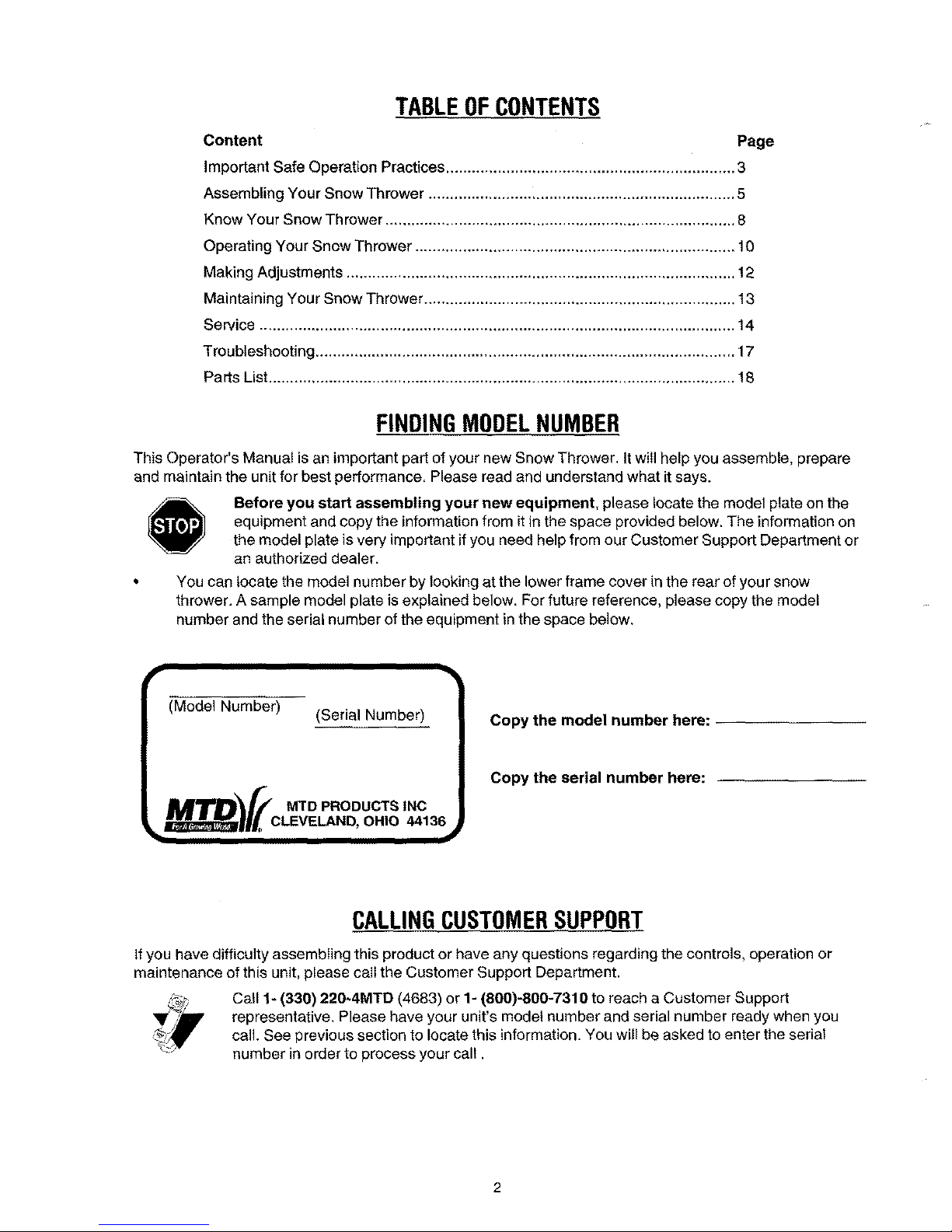
Before you start assembling your new equipment, please locate the model plate on the
equipment and copy the informationfrom itin the space provided below, The information on
the model plate is very important ifyou need help from our Customer Support Department or
an authorized dealer.
You can locate the model number by looking at the lower frame cover in the rear of your snow
thrower. A sample model plate is explained below. For future reference, please copy the model
number and the serial number of the equipment in the space below.
iv
(Model Number)
(Serial Number)
[.M=ZpTOV/co.o.°oooc..,°c
• o,,o,,t3,j
Copy the model number here:
Copy the serial number here:
CALLINGCUSTOMERSUPPORT
If you have difficulty assembling this product or have any questions regarding the controls, operation or
maintenance of this unit, please call the Customer Support Department.
Call 1- (330) 220*4MTD (4683) or 1- (800)-800-7310 to reach a Customer Support
representative. Please have your unit's model number and serial number ready when you
call. See previous section to locate this information. You will be asked to enter the serial
number in order to process your call.
Page 3
SECTION1: IMPORTANTSAFEOPERATIONPRACTICES
This symbol points out important safety instructions which, ifnot followed, could endanger the personal
safety and/or property of yourself and others. Read and follow all instructions in this manual before
attempting to operate this machine. Failure to comply with these instructions may result in personal
injury. When you see this symbol--heed its warning.
WARNING: Engine Exhaust, some of itsconstituents, and certain vehic-le components contain or emit
chemicals known to State of California to cause cancer and birth defects or other reproductive harm.
DANGER: This machine was built to be operated according to the rules for safe operation in this
manual. As with any type of power equipment, carelessness or error on the part of the operator can
result in serious injury. This machine is capable of amputating hands and feet and throwing objects.
Failure to observe the following safety instructions could result in serious injury or death.
Training
1. Read, understand and follow a]linstructions on the
machine and in the manual(s) before attempting to
assemble and operate. Keep this manual in a safe place
for future and regular reference and for ordering
replacement parts.
2. Be familiar with all controls and their proper operation.
Know how to stop the machine and disengage them
quickly.
3. Never allow children under 14 years old to operate this
machine. Children 14 years old and over should read and
understand the operation instructions and safety rules in
this manual and should be trained and supervised by a
parent.
4. Never allow adults to operate this machine without
proper instruction.
5. Thrown objects can cause serious personal injury. Plan
your snow throwing pattern to avoid discharge of material
toward roads, bystanders and the like.
6. Keep bystanders, helpers, pets and children at least 75
feet from the machine while it is in operation. Stop
machine if anyone enters the area.
7. Exercise caution to avoid slipping or falling, especially
when operating in reverse.
Preparation
1_ Thoroughly inspect the area where the equipment is to
be used. Remove all door mats, newspapers, sleds,
boards, wires and other foreign objects which could be
tripped over or thrown by the augedimpeller.
2_ Always wear safety glasses or eye shields during
operation and while performing an adjustment or repair to
protect your eyes. Thrown objects which ricochet can
cause serious injury to the eyes.
3. Do not operate without wearing adequate winter outer
garments. Do not wear jeweIry, long scarves or other
loose clothing which could become entangled in moving
parts. Wear footwear which will improve footing on
slippery surfaces.
4. Use a grounded three wire extension cord and receptacle
for all units with electric start engines.
5. Adjust collector housing height to clear gravel or crushed
rock surfaces.
_. Disengage all clutch levers before starting the engine.
7.
8.
9_
Never attempt to make any adjustments while engine is
running, except where _pecifically recommended in the
operator's manual.
Let engine and machine adjust to outdoor temperature
before starting to clear snow.
To avoid personaI injury or property damage use extreme
care in handling gasoline. Gasoline isextremely
flammable and the vapors are explosive, Serious
personal injury can occur when gasoline is spilled on
yourself or your clothes which can ignite. Wash your skin
and change clothes imrnediately.
a. Use only an approved gasoline container.
b. Extinguish all cigarettes, cigars, pipes and other
sources of ignition.
c. Never fuel machine indoors.
d. Never remove gas cap or add fuel while the
engine is hot or running.
e. Allow engine to cool at least two minutes before
refueling.
f. Never over fillfuel tank, Fill tank to no more than
_/2inch below bottom of filler neck to provide space
for fuel expansion.
g, Replace gasoline cap and tighten securely.
h. If gasoline is spilled, wipe it off the engine and
equipment. Move machine to another area. Wait 5
minutes before starting the engine.
i. Never store the machine or fuel container inside
where there is an open flame, spark or pilot light
(e.g. furnace, water heater, space heater, clothes
dryer etc.).
j, Allow machine to cool at least 5 minutes before
storing.
Operation
1. Do not put hands or feet near rotating parts, in the auger/
impeller housing or discharge chute. Contact with the
rotating parts can ampul:ate hands and feet.
2_ The auger/impeller clutch lever is a safety device. Never
bypass its operation. Doing so, makes the machine
unsafe and may cause personal injury.
3. The clutch levers must c,perata easily in both directions
and automatically return to the disengaged position when
released.
4. Never operate with a mi_sing or damaged discharge
Page 4
chute.Keepallsafetydevicesinplaceandworking.
5. Neverrunanengineindoorsorinapoorlyventilated
area.Engineexhaustcontainscarbonmonoxide,an
odorlessanddeadlygas.
6. Donotoperatemachinewhileundertheinfluenceof
alcoholordrugs.
7. Mufflerandenginebecomehotandcancauseaburn,DO
nottouch_
8, Exerciseextremecautionwhenoperatingonorcrossing
gravelsurfaces.Stayalertforhiddenhazardsortraffic.
9. Exercisecautionwhenchangingdirectionandwhile
operatingonslopes.
10.Planyoursnowthrowingpatterntoavoiddischarge
towardswindows,walls,carsetc. To avoid property
damage or personal injury caused by a ricochet.
11. Never direct discharge at children, bystanders and pets
or allow anyone in front of the machine.
12. DOnot overload machine capacity by attempting to clear
snow at too fast of a rate.
13. Never operate this machine without good visibility or light.
Always be sure of your footing and keep a firm hold on
the handles. Walk, never run.
14. Disengage power to the auger/impeller when
transporting or not in use.
15. Never operate machine at high transport speeds on
slippery surfaces. Look down and behind and use care
when in reverse.
16. If the machine should start to vibrate abnormally, stop the
engine, disconnect the spark plug and ground it against
the engine. Inspect thoroughly for damage. Repair any
damage before starting and operating.
17. Disengage all clutch levers and stop engine before you
leave the operating position (behind the handles). Wait
until the augedimpeller comes to a complete stop before
unclogging the discharge chute, making any
adjustments, or inspections.
18: Never put your hand in the discharge or collector
openings. Always use a clearing tool to unclog the
discharge opening.
19. Use only attachments and accessories approved by the
manufacturer (e,g. wheel weights, tire chains, cabs etc.).
20. If situations occur which are not covered in this manuaI,
use care and good judgment, Contact your dealer or
telephone 1-800-800-7310 for assistance and the name
of your nearest servicing dealer.
MaintenanceAndStorage
1. Never tamper with safety devices. Check their proper
operation regularly.
2. Disengage all clutch levers and stop engine. Wait until
the augedimpeller come to a complete stop. Disconnect
the spark plug wire and ground against the engine to
prevent unintended starting before cleaning, repairing, or
inspecting.
3. Check bolts, and screws for proper tightness at frequent
intervals to keep the machine in safe working condition,
Also, visually inspect machine for any damage.
4. Do not change the engine governor setting or over-speed
the engine. The governor controls the maximum safe
operating speed of the engine.
5. Snow thrower shave plates and skid shoes are subject to
wear and damage. For your safety protection, frequently
check all components and replace with original
equipment manufacturer's (O,EM.) parts only, "Use of
parts which do not meet the original equipment
specifications may lead to improper performance and
compromise safety!"
6, Check clutch controls periodically to verify they engage
and disengage properly and adjust, if necessary. Refer to
the adjustment section in this operator's manual for
instructions.
7. Maintain or replace safety and instruction labels, as
necessary.
8. Observe proper disposal laws and regulations for gas, oil,
etc. to protect the environment.
9. Prior to storing, run machine a few minutes to clear snow
from machine and prevent freeze up of auger/impeller.
10. Never store the machine or fuel container inside where
there is an open flame, spark or pilot light such as a water
heater, furnace ,clothes dryer etc.
11. Always refer to the operator's manual for proper
instructions on off-season storage.
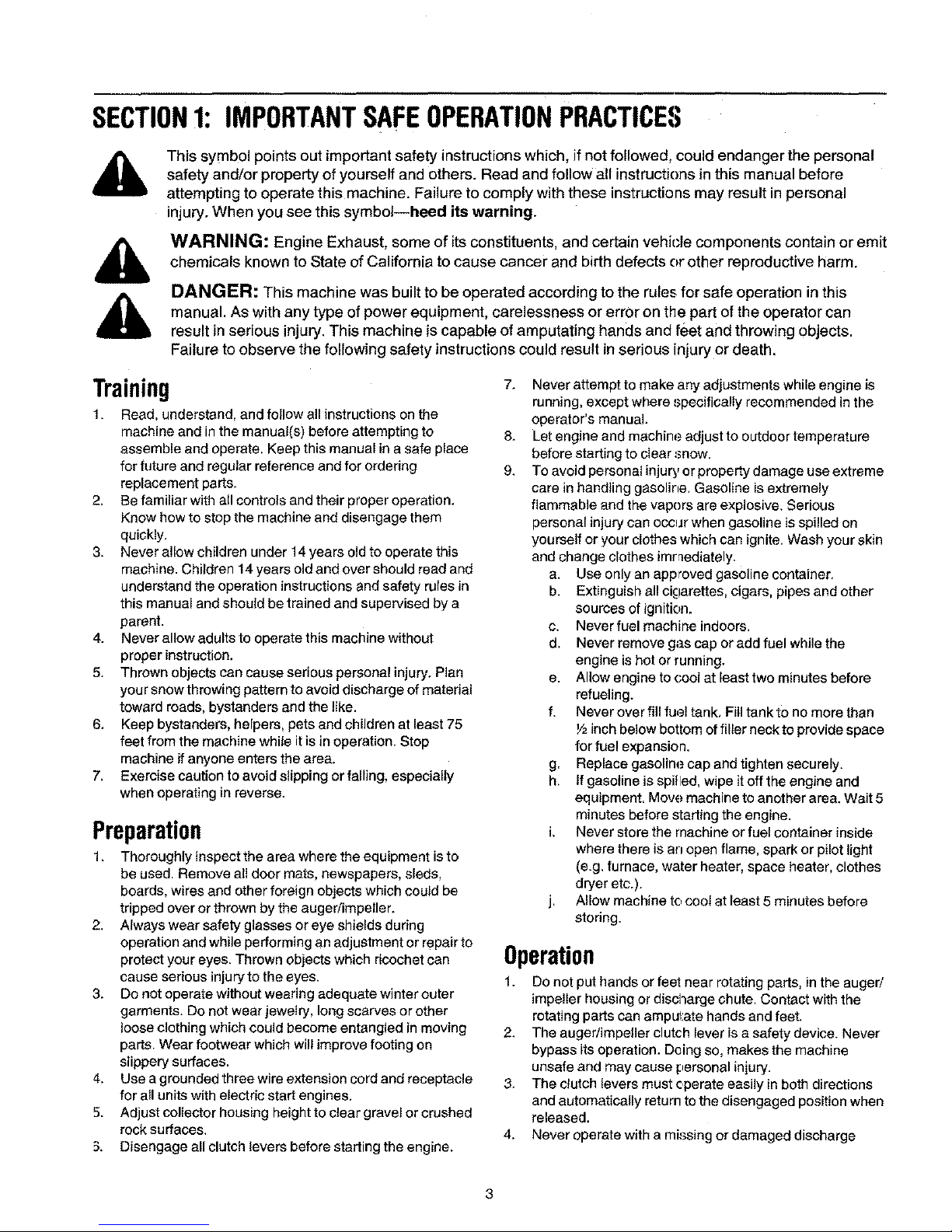
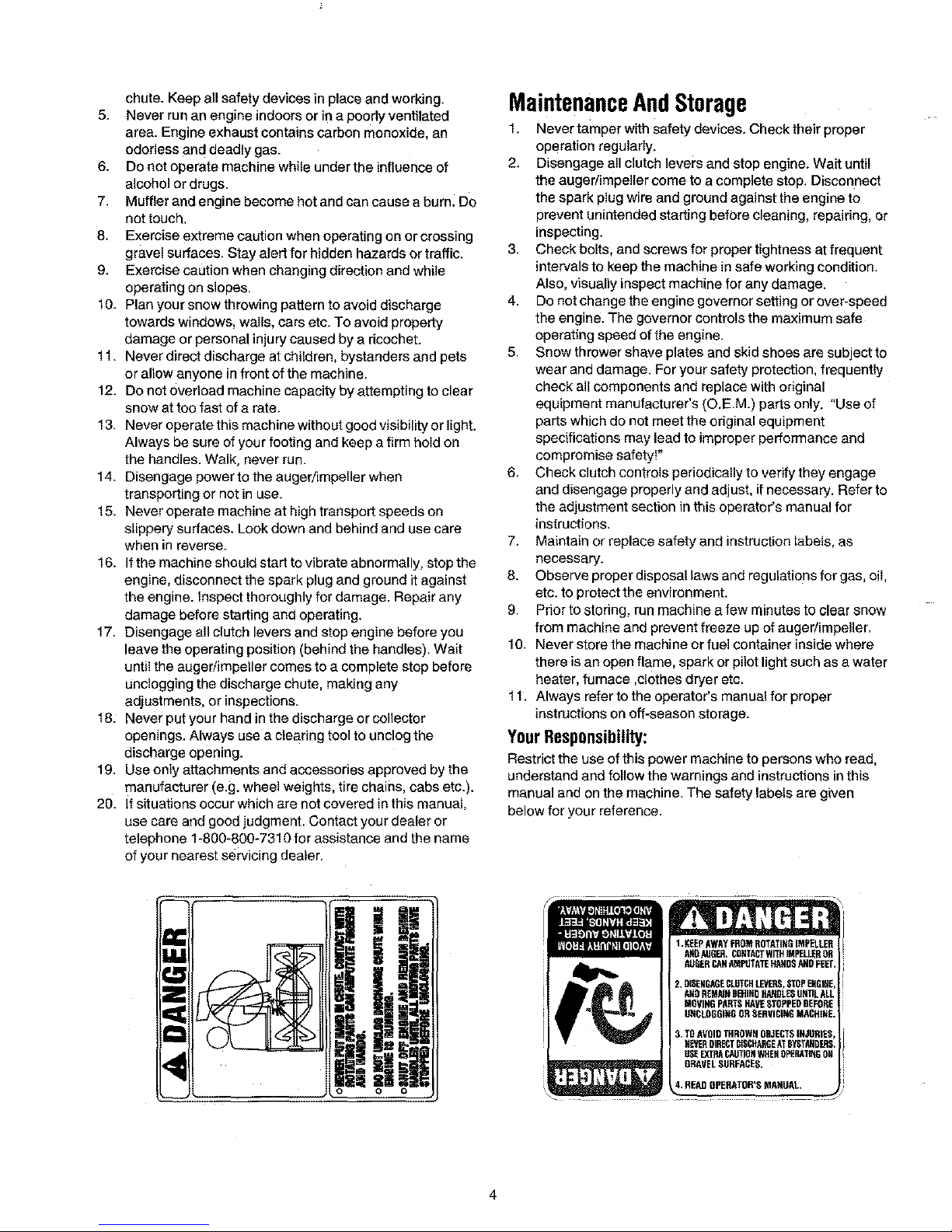
YourResponsibility:
Restrict the use of this power machine to persons wbo read,
understand and follow the warnings and instructions in this
manual and on the machine. The safety labels are given
below for your reference.
o o
Page 5
SECTION2: ASSEMBLINGYOURSNOWTHROWER
Unpacking
• Remove screws from the top sides and ends of the
shipping crate.
• Set panel aside to avoid tire punctures or personal
injury.
• Remove and discard plastic bag that covers unit.
• Roll unit out of crate.
° Check crate thoroughly for loose parts before
discarding.
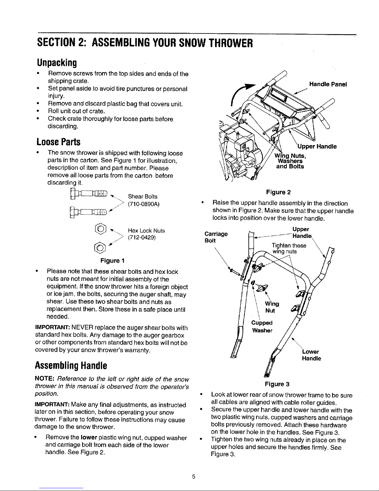
LooseParts
The snow thrower is shipped with following loose
parts in the carton. See Figure 1 for illustration,
description of item and part number. Please
remove all loose parts from the carton before
discarding it.
_ ",,-.\, ShearBolts
j2 (710-0890A)
and Bolts
Please note that these shear bolts and hex lock
nuts are not meant for initial assembly of the
equipment. If the snow thrower hits aforeign object
or ice jam, the bolts, securing the auger shaft, may
shear, Use these two shear bolts and nuts as
replacement then. Store these in a safe place until
needed.
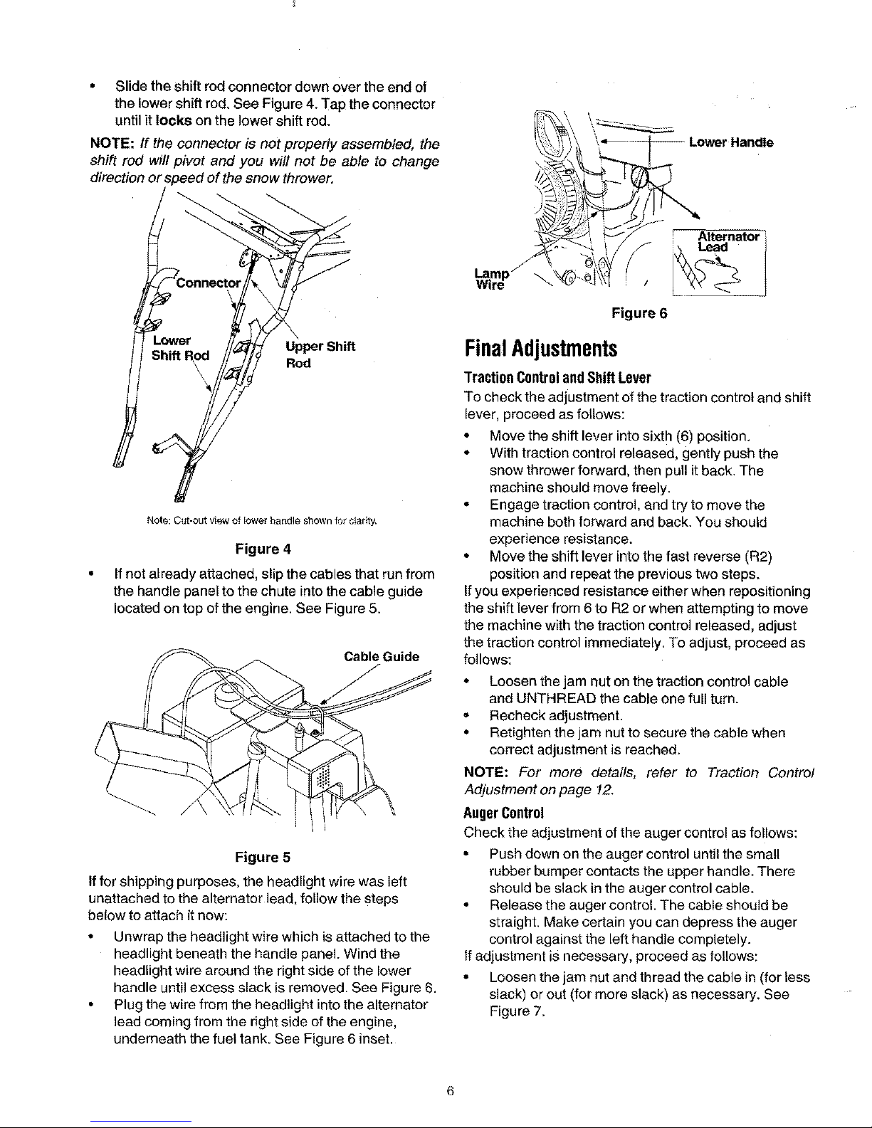
Fiigure 2
Handle Panel
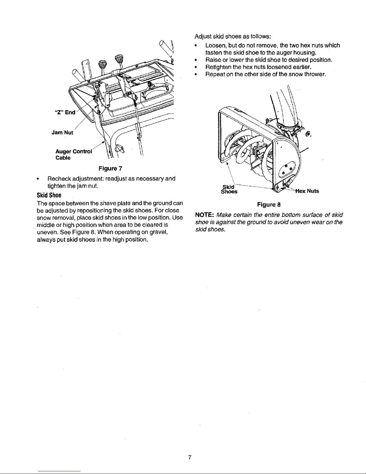
Raise the upper handle assembly in the direction
shown in Figure 2. Make sure that the upper handle
locks into position ovar the lower handle.
[_ "-._. Hex Lock Nuts Upper
(712-0429) Carriage
Bolt
[_} -_" Tighten these
wing nuts
Figure 1
IMPORTANT:NEVER replace the auger shear bolts with
standard hex bolts. Any damage to the auger gearbox
or other components from standard hex bolts will not be
covered by your snow thrower's warranty.
AssemblingHandle
NOTE: Reference to the left or right side of the snow
thrower in this manual is observed from the operator's
position.
IMPORTANT:Make any final adjustments, as instructed
later on in this section, before operating your snow
thrower. Failure to follow these instructions may cause
damage to the snow thrower.
• Remove the lower plastic wing nut, cupped washer
and carriage bolt from each side of the lower
handle. See Figure 2.
Wing
Nut
Cupped
Washer
Lower
Handle
Figure 3
• Look at lower rear of snow thrower frame to be sure
all cables are aligned with cable roller guides.
• Secure the upper handle and lower handle with the
two plastic wing nuts, cupped washers and carriage
bolts previously removed. Attach these hardware
on the lower hole in the handles. See Figure 3.
• Tighten the two wing nuts already in place on the
upper holes and secure the handles firmly. See
Figure 3.
5
Page 6
• Slide the shift rod connector down over the end of
the lower shift rod, See Figure 4. Tap the connector
until it locks on the lower shift rod.
NOTE: If th, ! connector is not properly assembled, the
shift rod will _ivot and you will not be able to change
direction or; _eed of the snow thrower,
_Connector
Lower
Shift Rod
\
Upper Shift
Rod
Note: Cut-out view of lower handle shown for clarity.
Figure 4
If not already attached, slip the cables that run from
the handle panel to the chute into the cable guide
located on top of the engine. See Figure 5,
Cable Guide
Figure 5
If for shipping purposes, the headlight wire was left
unattached to the alternator lead, follow the steps
below to attach it now:
• Unwrap the headlight wire which isattached to the
headlight beneath the handle panel. Wind the
headlight wire around the right side of the lower
handle until excess slack is removed, See Figure 6.
• Plug the wire from the headlight into the alternator
lead coming from the right side of the engine,
underneath the fuel tank. See Figure 6 inset.
Figure 6
FinalAdjustments
TractionControlandShiftLever
To check the adjustment of the traction control and shift
lever, proceed as follows:
• Move the shift lever intosixth (6) position.
• With traction control released, gently push the
snow thrower forward, then pull it back. The
machine should move freely.
• Engage traction control, and try to move the
machine both forward and back. You should
experience resistance.
• Move the shift lever into thefast reverse (R2)
position and repeat the previous two steps,
If you experienced resistance either when repositioning
the shift lever from 6 to R2 or when attempting to move
the machine with the traction control released, adjust
the traction control immediately. To adjust, proceed as
follows:
• Loosen the jam nut on the traction control cable
and UNTHREAD the cable one full turn.
- Recheck adjustment.
• Retighten the jam nut to secure the cable when
correct adjustment is reached.
NOTE: For more details, refer to Traction Control
Adjustment on page 12.
AugerControl
Check the adjustment of the auger control as follows:
• Push clown on the auger control until the small
rubber bumper contacts the upper handle. There
should be slack in the auger control cable.
• Release the auger control. The cable should be
straight. Make certain you can depress the auger
control against the left handle completely.
If adjustment is necessary, proceed as follows:
• Loosen the jam nut and th read the cable in (for less
slack) or out (for more slack) as necessary. See
Figure 7.
6
Page 7
Adjust skid shoes as follows:
• Loosen, but do not n.-.move,the two hex nuts which
fasten the skid shoe to the auger housing,
° Raise or lower the sldd shoe to desired position.
• Retighten the hex nuts loosened earlier.
° Repeat on the other side of the snow thrower.
"Z" End _
Jam Nut
J
Auger Control
Cable
Figure 7
• Recheck adjustment; readjust as necessary and
tighten the jam nut.
SkidShoe
The space between the shave plate and the ground can
be adjusted by repositioning the skid shoes. For close
snow removal, place skid shoes in the low position. Use
middle or high position when area to be cleared is
uneven. See Figure 8. When operating on gravel,
always put skid shoes in the high position.
Shoes _Hex Nuts
Figure 8
NOTE: Make certain the entire bottom surface of skid
shoe is against the ground to avoid uneven wear on the
skid shoes.
Page 8
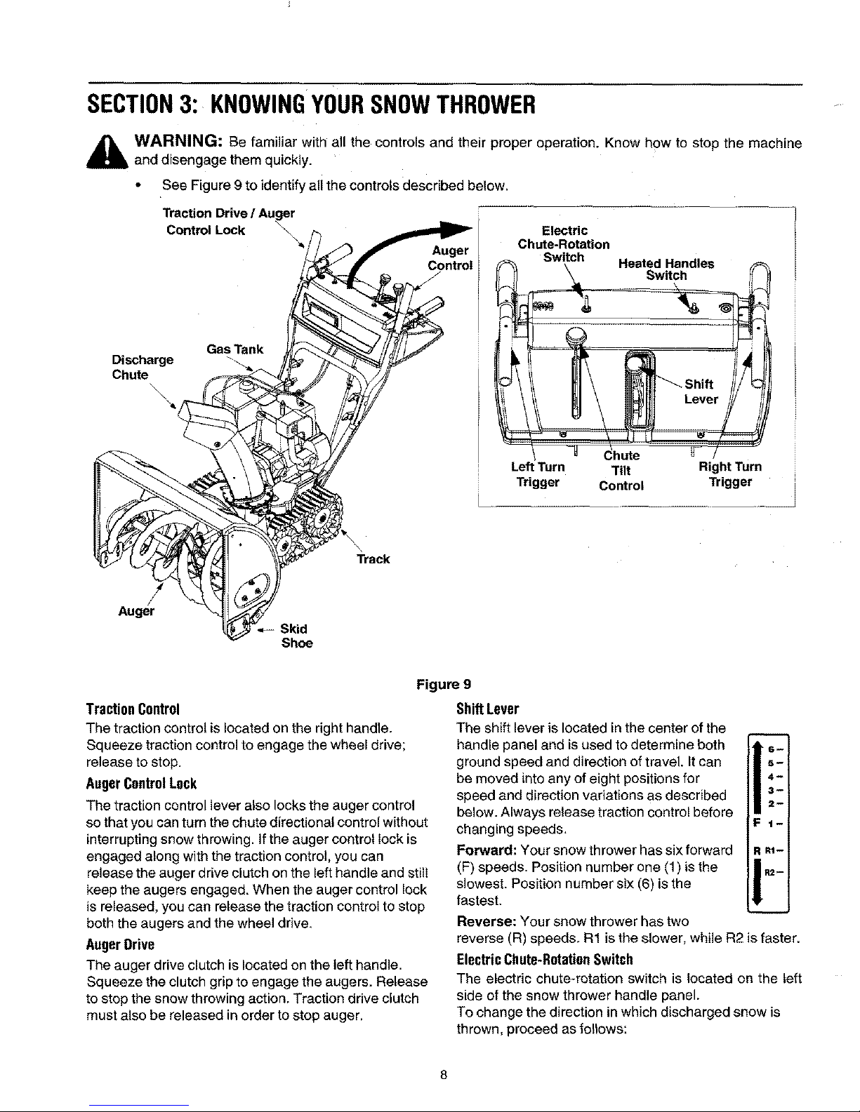
SECTION3: KNOWINGYOURSNOWTHROWER
_k WARNING: Be familiar with all the controls and their proper operation. Know how to stop the machine
and disengage them quickly.
• See Figure 9to identify all the controls described below.
Traction Drive / Auger
Control Lock
\
Auger
Control
Electric
Chute-Rotation
Switch
Heated Handles
Switch
Gas Tank
Discharge
Chute
Auger
\
Track
Skid
Shoe
hute
Left Turn Tilt Right Turn
Trigger Control Trigger
TractionControl
The traction control is located on the right handle.
Squeeze traction control to engage the wheel drive;
release to stop.
AugerControlLock
The traction control lever also locks the auger control
so that you can turn the chute directional control without
interrupting snow throwing. If the auger control lock is
engaged along with the traction control, you can
release the auger drive clutch on the left handle and still
keep the augers engaged. When the auger control lock
is released, you can release the traction control to stop
both the augers and the wheel drive.
AugerDrive
The auger drive clutch is located on the left handle.
Squeeze the clutch grip to engage the augers. Release
to stop the snow throwing action, Traction drive clutch
must also be released in order to stop auger,
Figure 9
Shift Lever
The shift lever is located in the center ofthe
handle panel and is used to determine both
ground speed and direction of travel. It can
be moved into any of eight positions for
speed and direction variations as described
below. Always release traction control before
changing speeds.
Forward: Your snow thrower has six forward
(F) speeds. Position number one (1) is the
slowest. Position number six (6) is the
fastest.
Reverse: Your snow thrower has two
reverse (R) speeds. R1 is the slower, while R2 is faster.
ElectricChute-RotationSwitch
The electric chute-rotation switch is located on the left
side of the snow thrower handle panel.
To change the direction in which discharged snow is
thrown, proceed as follows:
8
Page 9
• Push the toggle switch to the left to rotate the chute
counterclockwise.
• Push the toggle switch to the right to rotate the
chute clockwise.
IMPOFrI'ANT:Release the switch once the chute has
completed its rotation cycle in either direction. Failure to
do so can result in damage to the electric chute motor
and/or its drive gear.
Turn Trigger
The left and right turn triggers are located on the
underside of the handles and are used to assist in
steering the snow thrower. Squeeze the right trigger
when turning right; squeeze the left trigger when turning
left. Operate snow thrower in open areas until you
become familiar with these controls,
"Stay Warm" HandlesSwitch
This switch is located on the right side of the snow
thrower handle panel. To activate the heated handles,
toggle the switch to the right to generate heat within the
handles. Toggle the heated handles switch to the left
intothe OFF position after using the snow thrower.
NOTE: The heated handles are a compliment to, not a
substitute for, proper cold weather outerwear for hands.
It is recommended that the user wear adequate winter
protection for hands (like gloves/mittens) when
operating this snow thrower,
ChuteTilt Control
The distance snow is thrown can be changed by
adjusting the angle of the chute assembly. Move the
chute tilt control forward to decrease the distance, and
towards the rear to increase the distance.
DischargeChute
The angle of the discharge chute controls the distance
that the snow is thrown. Tilt the discharge chute up for
greater distance; tilt down for less distance.
SkidShoe
The position of the skid shoe is determined by the
condition of the ground from where snow has to be
removed. Refer to page 7 for details.
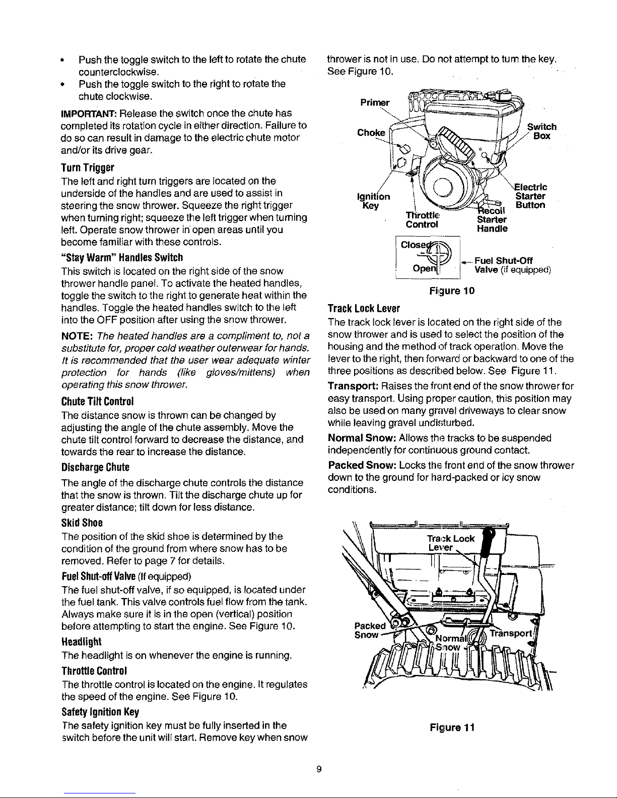
FuelShut-offValve(if equipped)
The fuel shut-oft valve, if so equipped, islocated under
the fuel tank. This valve controls fuel flow from the tank,
Always make sure it isin the open (vertical) position
before attempting to start the engine. See Figure 10.
Headlight
The headlight is on whenever the engine is running,
ThrottleControl
The throttle control is located on the engine, it regulates
the speed of the engine. See Figure 10.
SafetyIgnition Key
The safety ignition key must be fully inserted in the
switch before the unit will start. Remove key when snow
thrower is not in use, Do not attempt to turn the key.
See Figure 10.
Primer
Switch
Box
Starter
Button
Control Starter
Handle
?°se_/L_ "_.- Fuel Shut-Off
Op_n-F _1 Valve (if equipped)
Figure 10
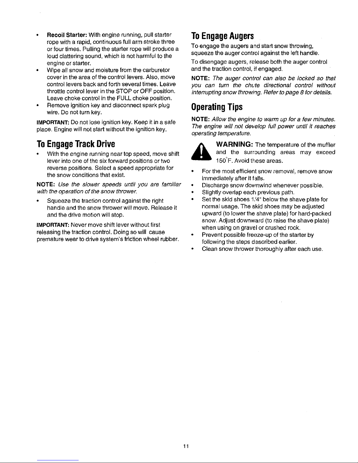
Track LockLever
The track lock lever is located on the right side of the
snow thrower and is used to select the position of the
housing and the method of track operation. Move the
lever to the right, then ronsard or backward to one of the
three positions as described below. See Figure 11.
Transport: Raises the front end of the snow threwe rfor
easy transport. Using proper caution, this position may
also be used on many gravel driveways to clear snow
while leaving gravel undisturbed.
Normal Snow: Allows the tracks to be suspended
independently for continuous ground contact.
Packed Snow: Locks the front end of the snow thrower
down to the ground for hard-packed or icy snow
conditions.
\
Packe¢
Figure 11
Page 10

SECTION4: OPERATINGYOURSNOWTHROWER
BeforeStarting
_lb ARNING: Read, understand, and follow
all instructions and warnings on the machine
and in this manual before operating.
• The spark plug wire was disconnected for safety.
Attach spark plug wire to spark plug before starting.
• Make certain the auger and drive clutch levers are
in the disengaged (released) position.
• Check oil and gasoline level and add if necessary.
Follow related instructions in the seperate engine
manual packed with your snow thrower.
WARNING: Use extreme care when
handling gasoline. Gasoline is extremely
flammable and the vapors are explosive.
Never fuel the machine indoors or while the
engine is hot or running. Extinguish cigarettes,
cigars, pipes and other sources of ignition.
ToStartEngine
• Make certain the fuel cut-off valve, if so equipped,
is inOPEN position.
• Move throttle control up to FAST position. Insert
ignition key into slot. Make sure it snaps into place.
Do not turn key.
NOTE: Engine wilt not start unless ignition key is
inserted into ignition slot in carburetor cover.
ElectricStarter
A
WARNING: The electric starter isequipped
with a grounded three-wire power cord and
plug, and is designed to operate on 120 volt
AC household current. It must be used with a
properly grounded three-prong receptacle at
all times to avoid the possibility of electric
shock. Fellow all instructions carefully prior to
operating the electric starter.
• Determine that your house wiring isa three-wire
grounded system. Ask a licensed electrician if you
are not certain.
• If your house wiring system is not a three-wire
grounded system, do not use this electric starter
under any conditions.
• If your home electrical system is grounded, but
a three-hole receptacle is net available, one should
be installed by a licensed electrician before using
the electric starter.
• If you have a grounded three-prong receptacle,
proceed as follows.
• Rotate choke knob to OFF position.
• Connect power cord to switch box on engine. Plug
the other end of power cord into a three-prong 120-
volt, grounded, AC receptacle.
• Push starter button to crank engine. As you crank
the engine, move choke knob to FULL choke
position.
. When engine starts, release starter button, and
move choke gradually to OFF. If engine falters,
move choke immediately to FULL and then
gradually to OFF.
• When disconnecting the power cord, always unplug
from the three-prong receptacle first, and then from
the snow thrower.
RecoilStarter
• Rotate choke knob to FULL choke position (cold
engine start).
• If engine is warm, place choke in OFF position
instead of FULL.
* Push primer button two or three times for cold
engine start.
o If engine iswarm, push primer button only once.
NOTE: Always cover vent hole in primer button when
pushing. Additional priming may be necessary for first
start ff temperature is below 15 degrees Fahrenheit.
• Grasp starter handle and pull rope out slowly, until
it pulls slightly harder. Let rope rewind slowly,
• Pul! starter handle rapidly. Do not allow handle to
snap back. Allow it to rewind slowly while keeping a
firm hold on the starter handle.
• As engine warms up and begins to operate evenly,
rotate choke knob slowly to OFF position. If engine
falters, return to FULL choke, then slowly move to
OFF position,
ToStopEngine
• To stop engine, push the throttle control lever to the
stop position. Remove the ignition key. Do not turn
key. Disconnect the spark plug wire from the spark
plug to prevent accidental starting while equipment
is unattended.
To preventpossiblefreeze-up ofstarter:
• Run engine for a few minutes before stopping to
help dry off any moisture on the engine.
• Electric Starter: Connect power cord to switch box
on engine, then to 120 volt AC receptacle. With the
engine running, push starter button and spin the
starter for several seconds. The unusual sound
made by spinning the starter will not harm engine or
starter. Disconnect the power cord from receptacle
first, and then from switch box.
10
Page 11
• Recoil Starter: With engine running, pull starter
rope with a rapid, continuous full arm stroke three
or four times. Pulling the starter rope will produce a
loud clattering sound, which is not harmful to the
engine or starter.
• Wipe all snow and moisture from the carburetor
cover in the area of the control levers. Also, move
control levers back and forth several times. Leave
throttle control lever in the STOP or OFF position.
Leave choke control in the FULL choke position.
• Remove ignition key and disconnect spark plug
wire. Do not turn key.
IMPORTANT: Do not Iose ignitionkey. Keep it in a safe
place, Engine will not start without the ignition key.
ToEngageTrackDrive
• With the engine running near top speed, move shift
lever into one of the six forward positions or two
reverse positions. Select a speed appropriate for
the snow conditions that exist.
NOTE: Use the slower speeds until you are familiar
with the operation of the snow thrower.
• Squeeze the traction control against the right
handle and the snow thrower will move. Release it
and the drive motion will stop.
IMPORTANT:Never move shift lever without first
releasing the traction control. Doing so will cause
premature wear to drive system's friction whee! rubber.
ToEngageAugers
TO engage the augers and start snow throwing,
squeeze the auger control against the left handle.
To disengage augers, release both the auger control
and the traction control, if engaged.
NOTE: The auger control can also be locked so that
you can turn the chute directional control without
interrupting snow throwirtg. Refer to page 8 for details.
OperatingTips
NOTE: Allow the engine to warm up for a few minutes.
The engine will not develop full power until it reaches
operating temperature.
_ WARNING: The temperature of the muffler
and the surrounding areas may exceed
150_F. Avoid these areas.
• For the most efficient snow removal, remove snow
immediately after it f_lls.
• Discharge snow downwind whenever possible.
• Slightly overlap each previous path.
• Set the skid shoes 1/4" below the shave plate for
normal usage. The skid shoes may be adjusted
upward (to bowerthe shave plate) for hard-packed
snow. Adjust downward (to raise the shave plate)
when using on gravel or crushed rock.
• Prevent possible freeze-up of the starter by
following the steps d_=scribedearlier.
• Clean snow thrower thoroughly after each use.
11
Page 12

SECTION5: MAKINGADJUSTMENTS
_, WARNING: NEVER attempt to clean
chute or make any adjustments while engine
is running.
TractionControl
Refer to Final Adjustments on page 6 to adjust traction
control, if you want to check further for correct
adjustment, proceed as follows:
WARNING: Drain the gasoline out of your
snow thrower's engine, and place a piece of
plastic film under the gas cap to avoid spillage
before beginning the job.
• Tip the snow thrower forward, allowing it to rest on
the auger housing.
• Remove frame cover underneath the snow thrower
by removing six self-tapping screws.
• With traction control released, make sure there is
clearance between the friction wheel and the drive
plate in all positions of the shift lever.
• With traction control engaged, make sure friction
wheel contacts the drive plate. See Figure 12.
ChuteAssembly
Refer to Chute Tilt Control on page 9,
SkidShoe
The space between shave plate and ground can be
adjusted by raising or lowering the skid shoes. Refer to
Skid Shoe Adjustment on page 7.
ShiftRod
To adjust the shift rod, proceed as follows.
• Remove the hairpin clip and slide the connector up
to separate the upper shift rod from the lower shift
rod. See Figure 13.
Hairpin Shift Lever
Clip
Fiat
Hex
Clutch Rod
Connecto=
Upper Shift Rod
Hairpin Clip
"Drive Plate
Lower Shift Rod
Figure 12
If either or both are lacking, adjust traction control as
instructed below:
• Loosen the jam nut on the traction drive cable and
thread the cable in or out as necessary.
• Retighten the jam nut to secure the cable when
correct adjustment is reached.
• Reassemble the frame cover.
NOTE: If you placed plastic film under the gas cap,
remove it now.
AugerControl
Refer to details on page 6 to adjust the auger control.
Figure 13
• Place shift lever in sixth (6) position.
• Rotate the shift arm counterclockwise (from the
operator's position) as far as it will go.
• Thread the upper shift rod downward until the
elbow on its lower end aligns with the hole in the
lower shift rod.
• Reconnect the upper shift rod to the lower shift rod
by reinserting the hairpin clip. Slide the connector
back into place.
IMPORTANT: Check for correct adjustment of the shift
rod as instructed on page 6, before operating the snow
thrower.
12
Page 13
SECTION6: MAINTAININGYOURSNOWTHROWER
Before lubricating, repairing, or inspecting,
disengage all clutch levers and stop engine.
Wait until all moving parts have come to a
complete stop. Disconnect spark plug wire
and ground it against the engine to prevent
unintended starting.
Lubrication
GearShaft
Lubricate the gear shaft with 6-in-1 grease (part
number 737-0170) at least once a season, or after
every 25 hours of operation. Refer to Figure 12.
IMPORTANT: Keep all grease and oil off the rubber
friction wheel and aluminum drive plate.
Engine
Refer to the seperate engine manual packed with your
unit for all engine lubrication instructions.
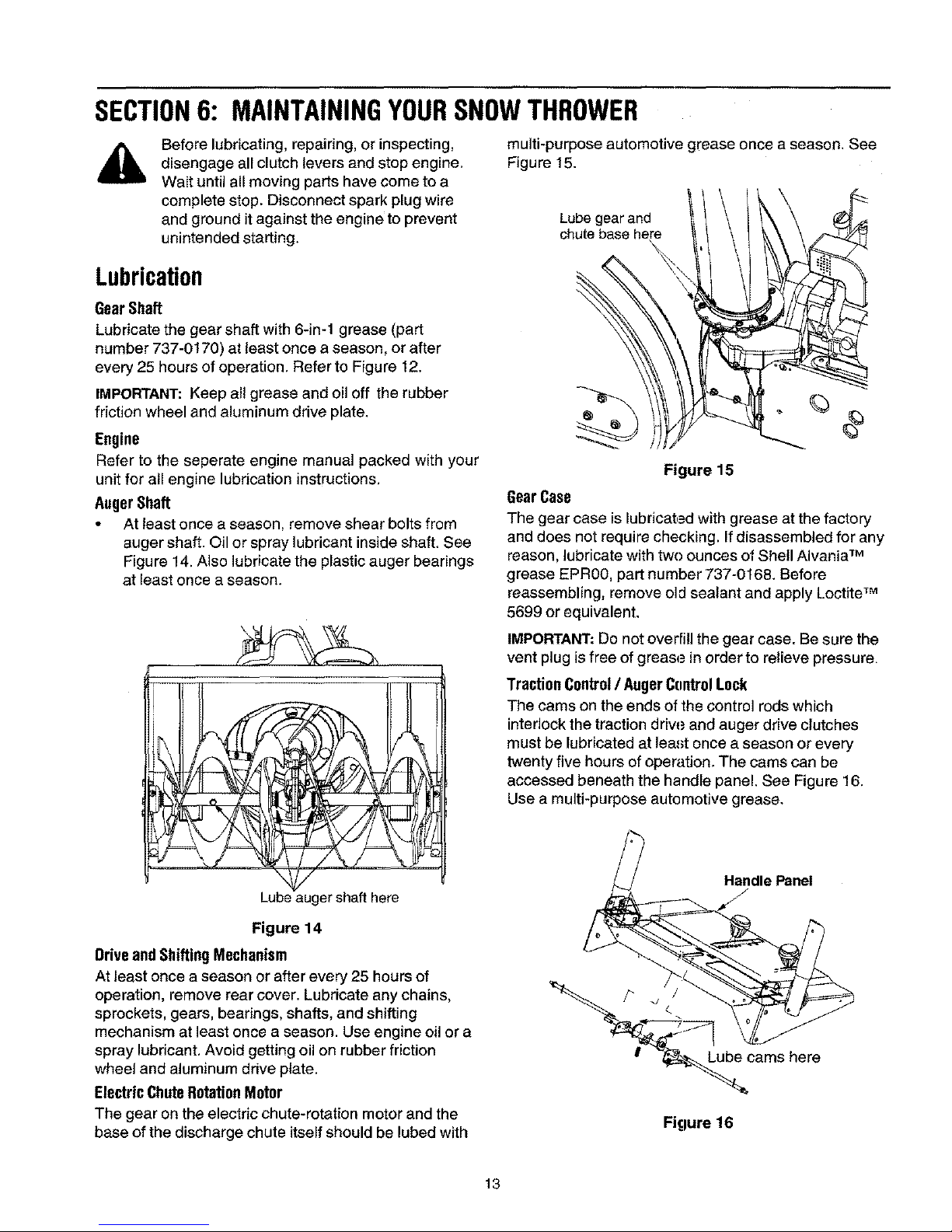
AugerShaft
• At least once a season, remove shear bolts from
auger shaft. Oil or spray lubricant inside shaft. See
Figure 14. Also lubricate the plastic auger bearings
at least once a season.
Lube auger shaft here
Figure 14
DriveandShiftingMechanism
At least once a season or after every 25 hours of
operation, remove rear cover. Lubricate any chains,
sprockets, gears, bearings, shafts, and shifting
mechanism at least once a season. Use engine oil or a
spray lubricant, Avoid getting oil on rubber friction
wheel and aluminum drive plate.
ElectricChuteRotationMotor
The gear on the electric chute-rotation motor and the
base of the discharge chute itself should be lubed with
multi-purpose automotive grease once a season. See
Figure 15.
Lube gear and
chute base here
%
Figure 15
GearCase
The gear case is lubricat,_=dwith grease at the factory
and does net require checking. If disassembled for any
reason, lubricate with twe ounces of Shell Alvania TM
grease EPR00, part number 737-0168. Before
reassembling, remove old sealant and apply Loctite TM
5699 or equivalent.
IMPORTANT: Do not overfill the gear case. Be sure the
vent plug is free of grease in order to relieve pressure.
TractionControl/ AugerControlLock
The cams on the ends of the control rods which
interlock the traction driw.=and auger drive clutches
must be lubricated at lea.,_tonce a season or every
twenty five hours of operation. The cams can be
accessed beneath the handle panel. See Figure 16.
Use a multi-purpose automotive grease.
__dle Panel
b/_ca ms here
Figure 16
13
Page 14

SECTION7: SERVICINGYOURSNOWTHROWER
A
WARNING: Before servicing, repairing, or
inspecting, disengage alI clutch levers and
stop engine. Wait until all moving parts have
come to a complete stop. Disconnect spark
plug wire and ground it against the engine to
prevent unintended starting.
Augers
The augers are secured to the spiral shaft with two
shear belts and hex lock nuts. See Figure 17. If you hit
a foreign object or ice jam, the snow thrower is
designed so that the bolts may shear.
T-_ Shear Bolts _-[
ii i
Figure 17
If the augers do not turn, check if the bolts have
sheared. Two replacement shear bolts and hex tock
nuts have been provided with the snow thrower. Refer
to Loose Parts on page 5. For future use, order kit
number OEM-710-0890.
IMPORTANT:NEVER replace the auger shear bolts with
standard hex bolts. Any damage to the auger gearbox
or other components, as a result of doing so, will NOT
be coved by your snow thrower's warranty.
ShavePlateandSkidShoes
• The shave plate and skid shoes on the bottom of
the snow thrower are subject to wear. They should
be checked periodically and replaced when
necessary.
• To remove skid shoes, remove the four carriage
bolts, belleville washers and hex nuts which attach
them to the snow thrower. Reassemble new skid
shoes with the hardware earlier removed. Make
certain the skid shoes are adjusted to be level.
• To remove shave plate, remove the carriage bolts,
belleville washers and hex nuts which attach it to
the snow thrower housing. Reassemble new shave
plate, making sure heads of the carriage bolts are
to the inside of the housing. Tighten securely.
BeltRemovalandReplacement
AugerBelts
• Remove the plastic belt cover on front of the engine
by removing the two self-tapping screws. See
Figure 18.
Self-Tapping
Screws
t Belt Cover
Auger Housing
Figure 18
• Drain the gasoline from the snow thrower, or place
a piece of plastic film under the gas cap.
• Tip the snow thrower up and forward so that it rests
on its auger housing.
• Remove six self-tapping screws from the frame
cover underneath the snow thrower.
• Roll the front and rear auger belts off the engine
pulley. See Figure 19.
Wheel
Pulley
Auger
Drive Wheel
Pulley _ Drive
Belt
Idler
Pulley
Idler
Pulley
Drive
Belts
Figure 19
14
Page 15

• Unhook the idler spring from the hex bolt on the
auger housing. See Figure 20.
• Back out the stop bolt until the support bracket
rests on the auger pulley. See Figure 21,
NOTE: It may be necessary to loosen the six nuts that
connect the frame to the auger housing to aid in belt
removal.
• Lift the rear auger belt from the auger puUey, and
slip belt between the support bracket and the auger
pulley. See Figure 20. Repeat this step for the front
auger belt.
* Replace both auger drive belts.
Friction Wheel-
Drive Platl
\
Suppo_
Rear
Auc
Belt
Auc
Belt
Auger
Pulley
Au_ler Bracket
Spring Housing Spring
Figure 20
NOTE: If you placed plastic film under the gas cap, be
certain to remove it before operating the snow thrower.
DriveBelt
• FoIIow the first four steps of instructions to service
the auger belts.
• Pull idler pulley up, and lift belt off engine pulley and
friction wheel disc. See Figure 19.
• Back out the stop bolt until the support bracket
rests on the auger pulley. See Figure 21,
• Slip belt between friction wheel and friction wheel
disc. See Figure 21. Remove and replace belt.
• Reassemble the parts removed earlier.
NOTE: The support bracket must rest on the stop bolt
after the new belt has been assembled, See Figure 21.
Figure 21
ChangingFrictionWheelRubber
The rubber on the frictien wheel is subject to wear and
should be checked after 25 hours of operation, and
periodically thereafter. Replace the friction wheel
rubber if any signs of wear or cracking are found.
• Drain the gasoline from the snow thrower, or place
a piece of plastic under the gas cap.Tip the snow
thrower up and forward, so that it rests on the
housing.
• Remove six self-tapping screws from the frame
cover underneath the snow thrower.
Figure 22
Using a wrench to hoId the shaft, loosen, but do not
completely remove, the hex bolt and bell washer on
the left end of shaft. See Figure 22.
Lightly tap the hex nut to dislodge the ball bearing
from the right side ol frame before removing the hex
nut and bell washer from left end of shaft.
Move the shaft to the right and slide the friction
wheel assembly from the shaft.
15
Page 16

Remove the six screws from the friction wheel
assembly (three from each side). Remove the
friction wheel rubber from between the friction
wheel plates. See Figure 23.
Screws
_ FrictionWheel Rubber
/ scrows
Friction Wheel Plates
Figure 23
Reassemble new friction wheel rubber to the
friction wheel plates and hub, tightening the six
screws in rotation and with equal force.
Position the friction wheel assembly up onto the pin
of the shift rod assembly, and slide the shaft
through the assembly. Reassemble the bearing
and the shaft and secure the frame cover.
Axle Shaft _
Shift Rod Assy
Pin
/
Drive Shaft Wheel
Assembly
Figure 24
NOTE: If you placed plastic film under the gas cap, be
certain to remove it.
Engine
• Refer to the engine manual for all engine related
service procedures.
SECTION8: OFF-SEASONSTORAGE
WARNING: Never store engine with fuel in
tank indoors or in poorly ventilated areas,
where fuel fumes may reach an open flame,
spark or pilot light as on a furnace, water
heater, clothes dryer or other gas appliance.
• If unit is to be stored over 30 days, prepare engine
for storage as instructedin the engine manual.
• Remove all debris from the exterior of equipment.
• Follow lubrication recommendations on page 13.
• Always store the snow thrower in a clean, dry area.
NOTE: When storing any type of power equipment in
an unventilated or metal storage shed, care should be
taken to rustproof the equipment. Using a light oil or
silicone, coat the equipment, especially any chains,
springs, bearings and cables.
16
Page 17

SECTION9: TROUBLESHOOTING
Problem Cause Remedy
Engine fails to start
Engine runs erratic
I
Loss of power
Engine overheats
1, Fuel tank empty, or stale fuel,
2. Blocked fuel line.
3. Choke not in ON position
4. Faulty spark plug.
5. Safety key not in ignition switch on engine,
6. Spark plug wire disconnected.
7. Primer button not being used propedy,
8. Fuel shut-off valve closed.
1. Unit running on CHOKE.
2, Blocked fuel line or stale fuel.
3. Water or dirt in fuel system.
4. Carburetor out of adjustment.
1. Spark plug wire loose.
2. Gas cap vent hole plugged.
3. Exhaust portplugged.
1. Carburetor notadjusted properly.
Excessive vibration 1. Loose parts or damaged auger, 1,
Unit fails 1. Traction control cable in need of adjustment. 1.
to propel itself
2. Drive belt loose or damaged, 2.
Unit fails 1. Discharge chute clogged. 1.
to discharge snow
2.
Foreign object lodged in auger.
Auger control cable in need of adjustment.
Auger belt loose or damaged,
Shear bolts sheared.
Loose electrical connections.
Blown Fuse.
1. Fill tank with fresh gasoline,
2. Clean the fuel line.
3. Move switch to ON position
4. Clean, adjust gap or replace.
5. Insert the key fully into the switch.
6. Connect spark plug wire.
7. Refer to the engine manual.
8, Open fuel shut-off valve.
1. Move choke lever to OFF position.
2, Clean fuel line; fill tank with clean, fresh
gasoline.
3. Drain fuel tank and carburetor. Refill with
fresh fuel.
4. Refer to the engine manual.
1. Connect and tighten spark plug wire.
2. Remove ice and snow from gas cap. Be
certain vent hole is clear.
3. Refer to the engine manual.
1. Refer to the engine manual or have the
carburetor adjusted by an authorized
engine service dealer.
Stop engine immediately and disconnect
spark plug wire. Tighten all bolts and nuts. If
vibration continues, have unit serviced by
an authorized service dealer.
2.
Adjust traction control cable. Refer to pages
6 and 12.
Replace drive belt. Refer to page 14.
Stop engine immediately and disconnect
spark phJgwire. Clean discharge chute and
inside of auger housing.
Stop engine immediately and disconnect
spark plug wire. Remove object from auger,
Refer to page 6for adjustment instructions.
Refer to page 14,
Replace shear bolts, Use new shear bolts.
3. 3.
4, 4,
5. 5,
Electric chute fails to 1. 1. Make sure all connections are tight and fully
turn installed.
2. 2. Replace with #5A fuse. The fuse is under
handle panel near switch connector.
Electric chute turns in 1. The switch connector is installed backwards 1, Unplug the switch connector under the
opposite direction of handle panel. Turn connector 180° and
the switch reconnect.
Heated grips are not 1. Loose electrical connections, 1, Under the handle panel, check connection;
creating heat from the handles to the wiring harness,
2. Blown fuse. 2, Replace with #5A fuse. The fuse is under
handle panel near switch connector.
3. Faulty grip. If one heated grip fails, both grips 3. Have the grips checked at an authorized
will not function, service cealer.
17
Page 18

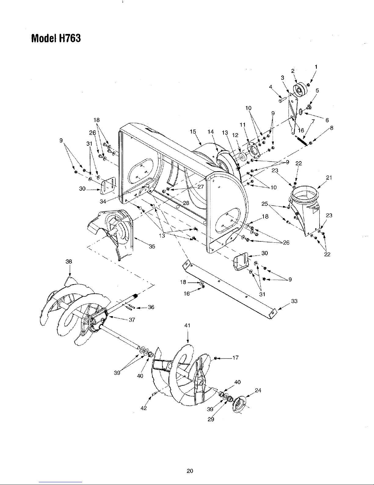
SECTION10: PARTSLISTFORMODELH763
2O
J
\
\\
"'-'37
31
v
J
52
\ J" 4
32
72
18
Page 19

ModelH763
Ref.
No.
15.
16.
17.
18.
19.
20.
21.
22.
23.
24,
25.
26.
27.
28.
29.
30.
31.
32.
33.
34.
35.
36.
37,
38,
39,
40.
Part No.
611-0053
618-0043
618-0044
618-0169
631-0032
656-0012A
683-0024
684-0009
684-0014B
684-0021
684-0024
684-0031
684-0038
684-0042C
710-0157
1710-0459A
710-0538
710-0599
710-0602
710-0604
710-0643
710-0809
710-0875
710-1231
1710-1652
i711-0911
711-1042
712-0214
i712-0346
712-0429
712-0711
713-0233
713-0413
713-0437
714-0474
719-0295A
j720-0223
721-0263
731-1292
I
731-1538A
Part Description
Axle Assembly: Track
Dogg Assembly: RH
Dogg Assembly: LH
Drive Shaft Assembly
Idler Wheel Assembly
Friction Wheel Disc
Hub Assembly
Track Pivot Rod Assembly
Shift Rod Assembly
Support Bracket: Friction Wheel
Axle Assembly: Idler
Frame Assembly
Handle Assembly: Track Lock
Wheel Ass'y.: Fric. WhL Bearing
Hex Screw: 5/16-24 x 0.75"
Hex Screw: 3/8-24 x 1.5"
Hex Screw: 5/16-18 x .625"
TT Screw: 1/4-20 x0,5 _
TT Screw: 5/16-18 x 1.0"
TT Screw: 5/16-18 x 0.625"
Hex Bolt: 5/16-18 x 1.0"
TT Screw: 1/4-20 x 1.25"
ITT Screw: 1/4-20 x 0.75"
I
Eye Bolt
TT Screw: 1/4-20 x 0.625"
Ref.
No.
41.
42.
43.
44,
45.
46.
47,
48.
49.
50.
51.
52.
53,
54.
55.
56.
57,
58.
59.
60.
61.
62.
63.
64.
65.
Part No,
i732-0209
i732-0264
i736-0105
i736-0160
!736-0178
!736-0242
736-0270
736-0272
736-0287
!736-0406
_737-0170
737-0318
738-0140
_738-0924
741-0339
741-0563
741-1111
746-0897
746-0898
746-0948
748-0190
748-0234
748-0353A
750-0547
750-0903
Part Description
Extension Spring
Extension Spring
Spring Washer
Flat Washer
Flat Washer
BeIeville Washer
Bell Washer
Fiat Washer
Flat Washer
Flat Washer
Lubricant
Grease
Shoulder Screw
Carriage Screw
Flange Bearing
Ball Bearing
Hex Flange Bearing
Clutch Cable: Auger
C,lutch Cable: Drive
_;teering Cable
Spacer
_;houlder Spacer
Lift Shaft Drive
S;pacer
Split Spacer
Actuator Shaft
Hex Shaft: Drive
Hex Lock Nut
Jam Lock Nut
Hex Lock Nut
Jam Nut
Chain
Sprocket
Chain
lCotter Pin
Track Housing
Grip
Adhesive: Loctite TM
Track
Track Wheel
66.
67.
68.
69.
70.
71.
72,
73.
74,
75.
76,
77.
78.
750-0904
750-0909
_750-0995
750-0997
756-0625
784-559O
784-5609
78_5639
784-5642
784-5648
784-5687A
784-5688
784-5689A
Split Spacer
Spacer
Spacer
Spacer
Cable Roller
Shift Bracket: Frame
Bracket: Steering Cable
Plate: Track Side
Plate: Track Lock out
Frame Cover
Cable Guide Bracket: Auger Clutch
Cable Guide Bracket: Drive Clutch
Cable Guide Bracket: Auger Clutch
Front Support
19
Page 20
ModelH763
1
2
3 /
4
\ 5
38
18
41
14 13
10
11
6
31
22
4O
40
24
42 39
29
2O
Page 21

ModelH763
2.
3.
4.
5.
6.
7.
8.
9.
10.
11.
12.
13.
14.
15.
t6.
17,
18,
19.
20,
Part
No.
712-0116
756-0178
784-5632A
710-0459A
738-0281
736-0167
732-0611
712-3068
712-3010
736-0119
05931
741-0309
710-0451
705-5226
684-0041C
737-0318
712-0429
736-0242
731-1379B
i712-0324
Description
LockJam Nut 3/8-24
Flat Idler
Auger Idler Arm
Hex Cap Screw 3/8-24 x 1.50
Shoulder Screw
Flat Washer
Extension Spring
Hex Nut 5/16-18
Hex Nut 5/16-18
Lock Washer 5/16
iHousing
Ball Bearing
Carriage Bolt 5/18-18 x .75
Chute Reinforcement
28" Housing Assembly
Grease: "Arctic"
Lock Nut 5/16-18
Bell Washer
Chute Adapter
Hex Lock Nut 1/4-20
-Ref.
No,
21.
22.
23.
Part
No=
736-0463
784-5618
710-0703
24, 710-0604
25. 1736-0169
26. 712-0798
Description
Flat Washer
Beadng Housing w/Fitting
Carriage Screw 1/4-20 x .75
Hex Washer Screw 5/16-18
Lock Washer 3/8
Hex Nut 3/8-16
27,
28,
29,
33.
34,
35.
36.
37.
38.
39.
40.
41,
42,
741-0245
784-5580
736-0242
784-5582A
710-0260
684-0065
715-0114
618-0122A
605-5196A
736-0188
i741-0493A
i605-5197A
1710-0890A
Hex Flange Bearing
Skid Shoe
Bell Washer
28" Shave Plate
Carriage Bolt 5/16-18 x .62
iImpeller Assembly
Pin
2E" Gear Assembly
Spiral 28" RH
Fl_t Washer
FI;_nge Bushing
Spiral 28" LH
Shear Bolt 5/16-18 x 1.5
21
Page 22

ModelH763
26
43
22
35
51
/
23
12
94' 83
89
/
9O
21
61
22
Page 23

ModelH763
Ref. No. Part No.
684-0008A
710-0262
710-0449
710-0788
710-0837
710-3008
711-0677
712-3010
714-0104
' 720-0284
725-1757
736-0119
736-0275
736-0451
747-0620A
747-0621
749-0951
749-0952A
749-0953A
750-0963
629-0936A
684-0036
884-0037A
710-1003
712-0271
; 712-0693
; 716-0398
', 720-0232
', 725-1672
725-1755
', 725-1756
725-1759
" 729-0164
731-2275
" 736-0226
747-1136
" _84-0102
' 710-0459A
, 710-0599
41. i711-0653
42. 712-0116
43. 712-0429
44. 714-0104
45. 732-0145
46. 732-0193
47. 732-0746
Part Description
Shift Arm Assembly
Carriage Bolt: 5/16-18 x 1.5"
Carriag Screw 5/16-18 x 2.25
TT Screw 1/4-20 x 1.0"
Oval C-Sunk AB Screw
Hex Screw 5/16-18 x 0.75"
Ferrule
Hex Nut
Hairpin Clip
Wing Nut
Heated Grip
Lock Washer
Flat Washer
Saddle Washer
Upper Shift Rod
Lower Shift Rod
Lower Handle
Upper Handle RH: L Style
Upper Handle LH: L Style
Shift Rod ConneCtor
Harness Assembly: Chute Crank
Handle Engagement RH
Handle Engagement LH
Special Screw
Sems Nut
Hex Nut
Lock Ring: Toggle Switch
Shift Knob
Lamp Housing
Toggle Switch: 2 Pos, Dbl. Throw
Toggle Switch: 2 Pos., SngL Throw
Halogen Lamp
Diode
Handle Panel
Fiat Washer
Headlight Retainer
Handle Panel Assembly w/Tilt
Hex Screw: Special
TT Screw: 1/4-20 x 0.5"
Clevis Pin
Jam Lock Nut
Hex Lock Nut
Hairpin Clip
Compression Spring
Compression Spring
Torsion Spring
R,;f.NO.
48.
49.
50.
51.
52.
53.
54.
55.
56.
57.
58.
59.
60.
61.
62.
63.
65.
66.
67.
68.
69.
70.
71.
72.
73.
74.
75.
76.
77.
78.
79.
81.
82.
83.
84.
85.
86.
87.
88.
89.
90.
91.
92.
93.
94.
Part No,
735-0199A
736-0105
736-0509
746-0778
747-0877
748-0362
748-0363
784-5619A
784-5679
784-5680
784-5661
784-5682
710-1233
712-0127
728-0157
746-0950
732-0705
618-0419
629-0937
710-0262
710-0451
710-0599
710-0602
710-0805
710-0817
710-0896
710-3008
712-0429
712-3010
712-3027
724-0249
731-0851A
731-1300A
731-1313C
731-1320
731-2279
736-0159
i736-0242
736-0606
746-0896
i746-0901
1750-1232
i782-0599
i764-5594
i784-5604
F
Part Description
Rubber Bumper
Spring Washer
Special Washer
Z Fitting
Cam Rod
Cam Handle Lock
Pawl: Handle Lock
Shift Handle
Handle Support Bracket 5/8: LH
Handle Support Bracket: RH
Handle Support Bracket 3/8: LH
Handle Support Bracket 3/8: LH
Oval C-Sunk Machine Screw
Flange Weld Nut
Cable Tie
Control Trigger
Cable Control Wire
Gear Assembly: Ring: Chut Rotatn.
Harness Assembly: Lower
Carriage Bolt: 5/16-18 x 1.5"
Carriage Bolt: 5/16-18 x ,750"
TT Screw 1/4-20 x 0.5"
1-1"Screw 5/16-18 x 1.0"
Hex Screw 5/16-18 x 1.5"
TT Screw 5/16-18 x 1.0"
AB Screw
1 ? ,216/1618x075,,
Hex Nut 5/16-18
Flange Lock Nut
Electric Motor: Chute Crank
Range Keeper
Lower Chute
Cable Guide: Chute Tilt
Upper Chute
Motor Cover
5/16 Washer
Beleville Washer
Special Washer
Chute Cable
Cable: Chute Deflector w/Clip
Spacer
Motor Bracket: Chute Rod
,Sable Bracket
Chute Tilt Handle
23
Page 24

ModelH763
2
26
\
19
21
22.
19\
1! 10
\
12 \ ,
18
7 6
13
i
!/
25
2O
IMPORTANT: For a proper working machine, use Factory
Approved Parts.
V-BELTS are specially designed to engage and disengage
safely. A substitute (non OEM) V-Belt can be dangerous by
not disengaging completely
24
Page 25

ModelH763
Ref. No.
1
2
3
4
5
6
7
8
9
10
11
12
13
14
15
16
17
18
19
20
2t
22
23
24
25
26
27
Part No.
710-1652
731-1324
732-0710
710-0627
710-3005
05896A
748-0234
756-0987
754-0346
756-0986
736-0270
710-0230
756-0313
710-1245
712-0181
756-0569
736-0242
736-0505
754-0430A
756-0967
736-0247
736-0331
710-0696
748-0360
1710-0654A
!629-0071
iOEM-390-987
Description
Hex Washer Screw 1/4-20 x ._._25
Belt Cover
Extension Spring
Hex Screw 5/16-24 x .75
Hex Cap Screw 3/8-16 x 1.25
Drive Clutch Idler Bracket
Shoulder Spacer
Pulley Half
V-Belt
Pulley Half
BelI Washer
Hex Cap Screw 1/4-28 x .50
Flat Idler
Lock Hex Cap Screw 5/16-24
Lock Jam Nut 3/8-16
Pulley Half
Bell Washer
Flat Washer
BeIt
Auger Pulley
Flat Washer 3/8 x 1.25 OD
Bell Washer
Hex Cap Screw 3/8-24
Adapter Pulley
Hex Screw 3/8-16 x 1.0
Extension Cord
Electric Start
25
Page 26

ModelH763
4
L
3.
4.
5.
6.
7.
8,
9.
10.
11.
12.
13.
14.
15.
16.
17.
Part No.
618-0123
618-0124
710-0642
7! 1-0910
714-0161
715-0143
717-0528
717-0526
718-0186
721-0325
721-0327
736-0351
736-0369
736-0445
741-0662
741-0663
618-0122A
Description
RH Reducer Housing
LH Reducer Housing
Hex Screw 1/4-20 x .75
Spiral Axle: 28"
Key
Pin-Spiral
Worm Gear, 20T
Worm Shaft
Thrust Collar
Grease Plug
Grease Seal
Flat Washer .76 x 1,5 x .030
Flat Washer .508 x 1.0 x .020
Flat Washer .76 x 1.5 x .060
Flange Bearing ,75 x 1.0 x .89
Flange Bearing .75 x 1.0 x ,925
Complete Assembly: 28"
26
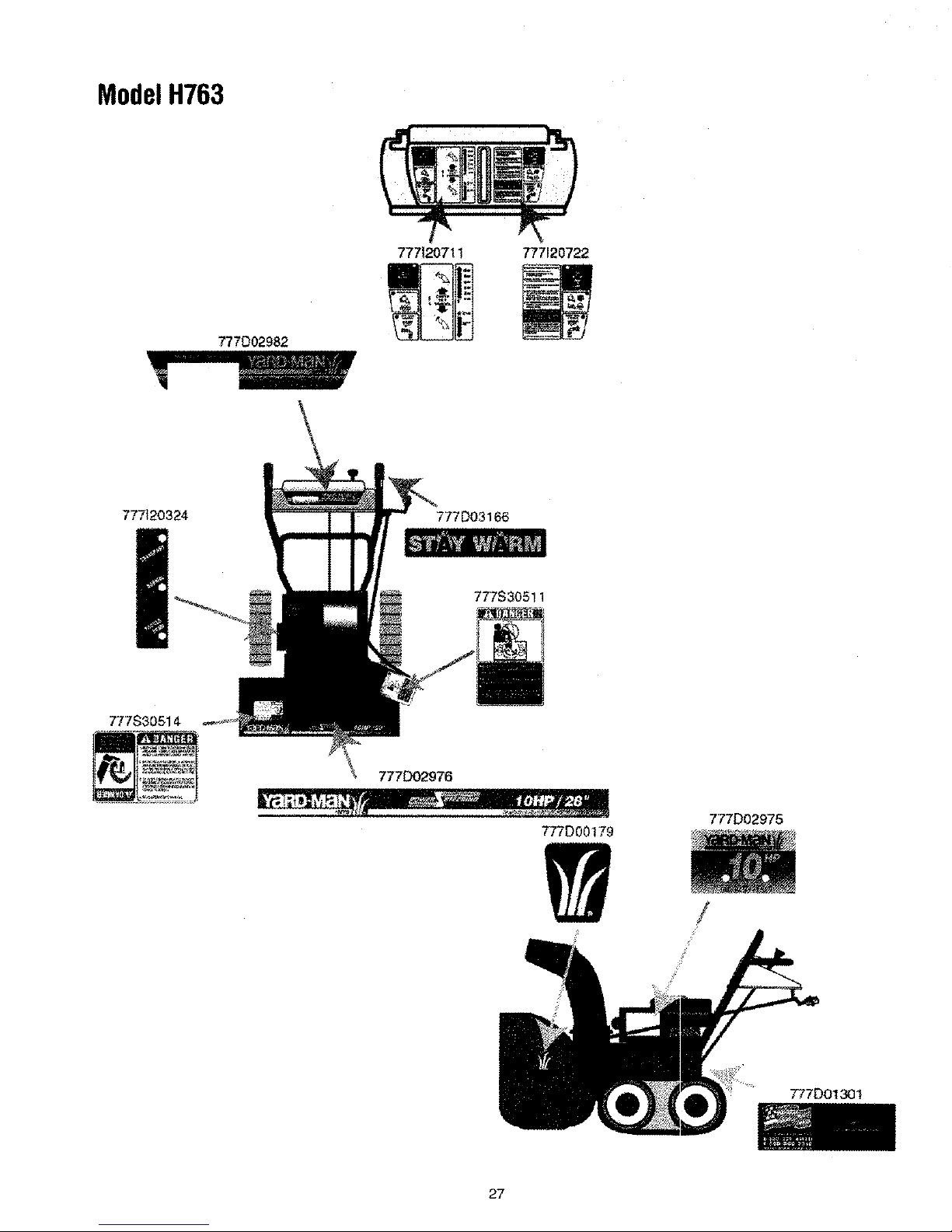
Page 27
ModelH763
777D02982
777120711 777120722
777_20324
777S30514
777D02976
777DO3166
777S3o5!1
777D00179
777D02975
!
777DO13_1
27
Page 28
MANUFACTURER'S LIMITED WARRANTY FOR:
The limited warranty set forth below is given by MTD
PRODUCTS INC ("MTD") with respect to new merchandise
purchased and used in the United States, its possessions
and territories.
MTD warrants this product against defects in material and
workmanship for a period of two (2) years commencing on
the date of original purchase and will, at its option, repair or
replace, free of charge, any part found to be defective in
material or workmanship. This limited warranty shall only
apply if this product has been operated and maintained in
accordance with the Operator's Manual furnished with the
product, and has not been subject to misuse, abuse, com-
mercial use, neglect, accident, improper maintenance,
alteration, vandalism, theft, fire, water or damage because
of other peril or natural disaster. Damage resulting from the
installation or use of any accessory or attachment not
approved by MTD Products Inc. for use with the product(s)
covered by this manual will void your warranty as to any
resulting damages.
Normal wear parts or components thereof are subject to
separate terms as follows: All normal wear part or compo-
nent failures will be covered on the product for a period of
90 days regardless of cause. After 90 days, but within the
two year period, normal wear part failures will be covered
ONLY IF caused by defects in material or workmanship of
OTHER component parts. Normal wear parts and compo-
nents include, but are not limited to, belts, blades, blade
adapters, grass bags, rider deck wheels, seats, snow
thrower skid shoes, shave plates and tires. Batteries are
covered by a 90-day limited replacement warranty.
HOW TO OBTAIN SERVICE: Warranty service is available,
WITH PROOF OF PURCHASE THROUGH YOUR LOCAL
AUTHORIZED SERVICE DEALER. To locate the dealer in
your area, please check for a listing in the Yellow Pages or
contact the Customer Service Department of MTD PROD-
UCTS INC by calling 1-800-800-7310 or writing to RO. Box
368022, Cleveland, Ohio 44136-9722. No product returned
directly to the factory will be accepted unless prior written
permission has been extended by the Customer Service
Department of MTD PRODUCTS INC.
This limited warranty does not provide coverage in the
following cases:
a. The engine or component parts thereof. These items
carry a separate manufacturer's warranty. Please refer
to the applicable manufacturer's warranty on these
items.
b. Routine maintenance items such as lubricants, filters,
blade sharpening and tune-ups, or adjustments such
as brake adjustments, clutch adjustments or deck
adjustments; and normal deterioration of the exterior
finish due to use or exposure.
c. Log splitter pumps, valves and cylinders have a sepa-
rate one year warranty.
d. MTD does not extend any warranty for products sold
or exported outside of the United States of America,
its possessions and territories, except those sold
through MTD's authorized channels of export distribu-
tion.
No implied warranty, including any implied warranty of
merchantability or fitness for a particular purpose,
applies after the applicable period of express written
warranty above as to the parts as identified. No other
express warranty or guaranty, whether written or oral,
except as mentioned above, given by any person or
entity, including a dealer or retailer, with respect to any
product shall bind MTD. During the period of the War-
ranty, the exclusive remedy is repair or replacement of
the product as set forth above. (Some states do not
allow limitations on how long an implied warranty lasts, so
the above limitation may not apply to you.)
The provisions as set forth in this Warranty provide the
sole and exclusive remedy arising from the sales. MTD
shall not be liable for incidental or consequential loss
or damages including, without limitation, expenses
incurred for substitute or replacement lawn care ser-
vices, for transportation or for related expenses, or for
rental expenses to temporarily replace a warranted
product. (Some states do not allow the exclusion or limita-
tion of incidental or consequential damages, so the above
exclusion or limitation may not apply to you.)
In no event shall recovery of any kind be greater than the
amount of the purchase price of the product sold. Alteration
of the safety features of the product shall void this War-
rarity. You assume the risk and liability for loss, damage, or
injury to you and your property and/or to others and their
property arising out of the use or misuse or inability to use
the product.
This limited warranty shall not extend to anyone other than
the original purchaser, original lessee or the person for
whom it was purchased as a gift.
How State Law Relates to this Warranty: This limited
warranty gives you specific legal rights, and you may also
have other rights which vary from state to state.
 Loading...