

Page 1
OPERATOR’S MANUAL
33” Snow Thrower
Model 31AE993I401
IMPORTANT: READ SAFETY RULES AND INSTR UCTIONS CAREFULLY
Warning: This unit is equipped with an internal combustion engine and should not be used on or near any unimproved forest-
covered, brush-covered or grass-covered land unless the engine’s exhaust system is equipped with a spark arrester meeting
applicable local or state laws (if any). If a spark arrester is used, it should be maintained in effective working order by the operator.
In the State of California the above is required by law (Section 4442 of the California Public Resources Code). Other states may have
similar laws. Federal laws apply on federal lands. A spark arrester for the muffler is available through your nearest engine authorized
service dealer or contact the service department, P.O. Box 368022 Cleveland, Ohio 44136-9722.
MTD PRODUCTS INC. P.O. BOX 368022 CLEVELAND, OHIO 44136-9722
PRINTED IN U.S.A.
FORM NO.
770-10278B.fm
(5/2001)
Page 2
TABLE OF CONTENTS
Content Page
Important Safe Operation Practices...................................................................3
Assembling Your Snow Thrower .......................................................................5
Knowing Your Snow Thrower ............................................................................7
Operating Your Snow Thrower ..........................................................................9
Making Adjustments ..........................................................................................10
Maintaining Your Snow Thrower........................................................................12
Servicing Your Snow Thrower ...........................................................................13
Off-Season Storage...........................................................................................17
Trouble Shooting Guide.....................................................................................18
Parts List............................................................................................................19
FINDING MODEL NUMBER
This Operator’s Manual is an important part of your new snow thrower. It will help you assemble, prepare
and maintain the unit for best performance. Please read and understand what it says.
Before you star t to prepa re yo ur sno w thr ower for its first use, please locate the model
plate and copy the information from it in this Operator’s Manual. The information on the
model plate is very important if you need help from your dealer or the Customer Support
Department.
You can locate the model number by looking at the lower frame cover on the rear of your snow thrower. A
sample model plate is explained below. For future reference, please copy the model number and the serial
number of the equipment in the space below.
(Model Number)
CLEVELAND, OHIO 44136
(Serial Number)
MTD PRODUCTS INC
Copy the model number here:
Copy the serial number here:
CALLING CUSTOMER SUPPORT
If you have difficulty assembling this product or have any questions regarding the controls, operation or
maintenance of this unit, please call the Customer Support Department.
Call 1- (330) 220-4MTD (4683) or 1- (800)-800-7310 to reach a Customer Support
representative. Please have your unit’s model number and serial number ready when you
call. See previous section to locate this information. You will be asked to enter the serial
number in order to process your call.
For more details about your unit, visit our website at www.yardman.com
2
Page 3

SECTION 1: IMPORTANT SAFE OPERATION PRACTICES
This symbol points out important safety instructions which, if not followed, could endanger the personal
safety and/or property of yourself and others. Read and follow all instructions in this manual before
attempting to operate this machine. Failure to comply with these instructions may result in personal
injury. When you see this symbol—heed its warning.
WARNING: Engine Exhaust, some of its constituents, and certain vehicle components contain or emit
chemicals known to State of California to cause cancer and birth defects or other reproductive harm.
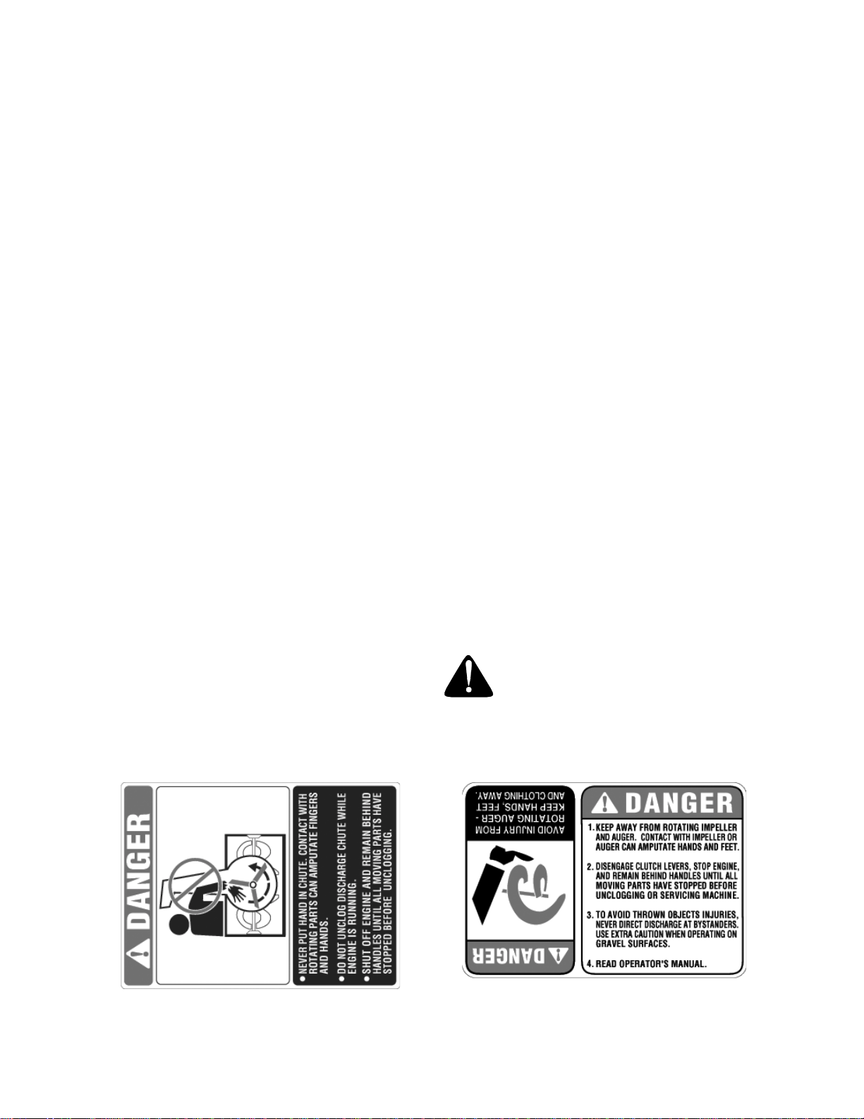
DANGER: This machine was built to be operated according to the rules for safe operation in this
manual. As with any type of power equipment, carelessness or error on the part of the operator can
result in serious injury. This machine is capable of amputating hands and feet and throwing objects.
Failure to observe the following safety instructions could result in serious injury or death.
Training
1. Read, understand, a nd follow all in struction s on the
machine and in the manual(s ) before a ttempting to
assemble and o perate. Keep this ma nual in a safe pl ace
for future and regular re ference a nd for orde ring
replacement parts.
2. Be familiar with all controls and their prope r operation.
Know how to stop the mach ine and d isengage them
quickly.
3. Never allow childre n under 14 y ears old to operate this
machine. Children 14 years old and over should rea d and
understand the op eration in struction s and sa fety rules i n
this manual and should be trained and sup ervised b y a
parent.
4. Never allow adults to operate this machine without
proper instruction.
5. Thrown objects can cause seriou s personal injury . Plan
your snow throwin g pattern to avoid di scharge of mat erial
toward roads, bystanders and the like.
6. Keep bystanders, hel pers, pets and chi ldren at l east 75
feet from the machin e while it is in operatio n. Stop
machine if anyo ne enters the area.
7. Exercise caution to avoid s lipping o r falli ng, espe cially
when operating in reverse.
Preparation
1. Thoroughly inspect the area wh ere the eq uipment i s to
be used. Remove all door mat s, newspa pers, sle ds,
boards, wires and o ther foreig n object s which c ould be
tripped over or throw n by the auger/imp eller.
2. Always wear safet y glasses or eye s hields d uring
operation and while performing an adjustment or repair to
protect your eyes. T hrown ob jects whi ch ricochet can
cause serious inj ury to the eyes.
3. Do not operate wit hout wearing adequate winter outer
garments. Do not wear jewelry, long scarves or other
loose clothing which cou ld becom e entang led in m oving
parts. Wear footwear w hich wi ll improve footing on
slippery surfaces.
4. Use a grounded three wire ex tension cord and receptac le
for all units with electric start engi nes.
5. Adjust collector housing height to clear gravel or crushed
rock surfaces.
6. Disengage all cl utch levers before st arting the engin e.
7. Never attempt to m ake any adjustme nts while engine i s
running, except where spec ifically recomm ended in the
operator’s manual.
8. Let engine and m achine adju st to outd oor tem perature
before starting to clear snow.
9. To avoid personal injury or pro perty damage use extre me
care in handling gasolin e. Gasol ine is e xtremely
flammable and the v apors are explosiv e. Serious
personal injury c an occur w hen gas oline is spilled o n
yourself or your c lothes which c an ignit e. Wash y our skin
and change clot hes immedi ately.
a. Use only an approved gasoline container.
b. Extinguish all cigarettes, cig ars, pipes and other
sources of ignition.
c. Never fuel machine indoo rs.
d. Never remove gas cap or add fue l whil e the
engine is hot or running.
e. Allow engine to cool at leas t two minu tes before
refueling.
f. Never over fill fuel tank. Fil l tank to no more tha n
½ inch below bottom of fill er neck to provide space
for fuel expansi on.
g. Replace gasoli ne cap an d tighten secu rely.
h. If gasoline is sp illed, wip e it off th e engine and
equipment. Move machine to another area . Wait 5
minutes before start ing the e ngine.
i. Never store the machine or fuel containe r inside
where there is an o pen flam e, spark or pilot l ight
(e.g. furnace, water heater, space heate r, clothes
dryer etc.).
j. Allow machine to cool 5 minute s before storin g.
Operation
1. Do not put hands o r feet near rotating p arts, in the a uger/
impeller housing o r disc harge chu te. Cont act wit h the
rotating parts can am putate ha nds and feet.
2. The auger/impelle r clutch lev er is a safety de vice. Nev er
bypass its operati on. Doing so, makes the ma chine
unsafe and may cause p ersonal i njury.
3. The clutch leve rs must o perate easily in both d irections
and automatical ly return to the disengaged pos ition when
released.
4. Never operate with a miss ing or da maged di scharge
chute. Keep all safe ty devic es in pl ace and working.
3
Page 4
5. Never run an engine indoors or in a poorly vent ilated
area. Engine exhaust contains carbon monoxide , an
odorless and dea dly gas .
6. Do not operate mac hine while under the influenc e of
alcohol or drugs.
7. Muffler and engine be come hot and c an cause a burn. D o
not touch.
8. Exercise extreme ca ution when operating on or cro ssing
gravel surfaces. Stay alert for hidden hazards or traffic.
9. Exercise caution w hen changi ng directi on and w hile
operating on slop es.
10. Plan your snow t hrowing pat tern to av oid disc harge
towards windows, wa lls, cars e tc. To avoid prope rty
damage or personal injury caus ed by a ricochet.
11. Never direct disc harge at c hildren, b ystander s and pet s
or allow anyone in front of t he machi ne.
12. Do not overload machine capa city by attemptin g to clear
snow at too fast of a rate.
13. Never operate this machin e without good visib ility or light.
Always be sure of your footi ng and k eep a firm hold on
the handles. Walk, n ever run.
14. Disengage power to t he aug er/impeller w hen
transporting or not in use.
15. Never operate mach ine at hi gh transp ort speeds on
slippery surfaces. Look down and b ehind an d use ca re
when in reverse.
16. If the machine shoul d start to vibrate abn ormally, stop the
engine, disconnect the spark plug an d grou nd it agai nst
the engine. Inspect thoroughly for dam age. Repair any
damage before starting and ope rating.
17. Disengage all cl utch lev ers and st op engin e before y ou
leave the operating position (be hind the handles). Wai t
until the auger/im peller come s to a complete stop befo re
unclogging the d ischarge chute, m aking an y
adjustments, or inspecti ons.
18. Never put your hand in the d ischarge or colle ctor
openings. Always use a cl earing to ol to unc log the
discharge opening.
19. Use only attach ments a nd acce ssories approved by the
manufacturer (e.g. wheel weigh ts, tire c hains, cabs etc.) .
20. If situations occur which are not covered in this manua l,
use care and good judgment. Cont act your dealer or
telephone 1-800-800-73 10 for assistance and the name
of your nearest s ervicing dealer.
Maintenance And Storage
1. Never tamper with safety devices. Check their proper
operation regularly.
2. Disengage all cl utch lev ers and stop engi ne. Wait u ntil
the auger/impelle r come to a complet e stop. D isconn ect
the spark plug wi re and grou nd again st the en gine to
prevent unintended starting before cl eaning, repairi ng, or
inspecting.
3. Check bolts, and sc rews for pro per tig htness at frequent
intervals to keep t he ma chine in safe worki ng condi tion.
Also, visually inspe ct mach ine for an y damag e.
4. Do not change the engi ne governor settin g or over-speed
the engine. The g overnor c ontrols the m aximum s afe
operating speed o f the eng ine.
5. Snow thrower shave plates an d skid shoes are subj ect to
wear and damage. F or your s afety protecti on, freque ntly
check all compon ents and replace with origin al
equipment manufac turer’s (O.E.M.) pa rts only. Use of
parts which do not m eet the ori ginal eq uipment
specifications may lea d to imp roper perfor mance an d
compromise safety.
6. Check clutch co ntrols period ically to verify they engage
and disengage prope rly and adjust, if ne cessary. Refer to
the adjustment s ection i n this op erator’s manual for
instructions.
7. Maintain or replace safety and instruction labels, as
necessary.
8. Observe proper disposal l aws and regulations for ga s, oil,
etc. to protect the environmen t.
9. Prior to storing, run machine a few minutes to clear snow
from machine an d prevent freeze up of auger/i mpeller.
10. Never store the machine or fuel c ontainer i nside whe re
there is an open flame, spark or pilot light such as a wate r
heater, furnace ,cloth es dryer etc .
11. Always refer to the operator’s ma nual for p roper
instructions on off-season storage.
WARNING: Restrict the use of this
power machine to persons who read,
understand and follow the warnings and
instructions in this manual and on the
machine.
4
Page 5

SECTION 2: ASSEMBLING YOUR SNOW THROWER
NOTE: Any reference in this manual to the left or right
side of the snow thrower is observed from the
operator’s position.
Upper Handle
Unpacking
• Remove staples from the top, sides, and ends of
the shipping crate.
• Set panels aside to avoid tire punctures or personal
injury.
• Remove and discard plastic bag that covers unit.
• Roll the unit out of the crate.
• Check the crat e thorough ly for loos e parts bef ore
discarding.
Loose Parts
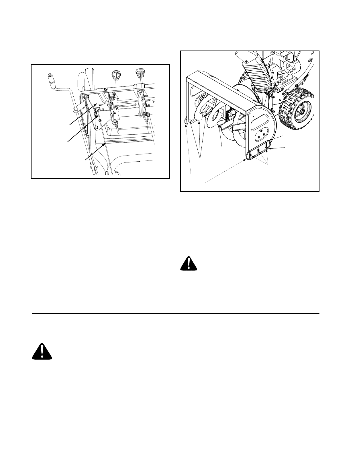
• The augers are secured to the auger shaft with two
shear bolts and hex lock nuts. If you hit a foreign
object or ice jam, the snow thrower is designed so
that the bolts may shear. Two replacement shear
bolts and nuts are provided for your convenience.
Store in a safe place until needed. See Figure 1.
Shear Bolts
Figure 1
Hex Lock
Nuts
Steering Cable
Tighten these
Wing Nuts
Lower Handle
Cable Tie
Upper Shift Rod
Clutch Rod
Connector
Carriage Bolt
Cupped Wa she r
Wing Nut
Upper Shift Rod
Figure 2
• Raise the upper handle assembly until it locks over
the lower handle. See Figure 3.
• Look at the lower rear of the snow thrower frame to
be sure all the cables are aligned with the cable
roller guides.
IMPORT ANT :
standard hex bolts. Any damage to the auger gearbox
or other components from standard hex bolts will not be
covered by your snow thrower’s warranty.
NEVER replace the auger shear bolts with
Assembling Handle
WARNING: Disconnect the spark plug
wire and ground it against the engine to
prevent unintended starting.
IMPORT ANT :
later on in this section, before operating your snow
thrower. Failure to follow these instructions may cause
damage to the snow thrower.
• Remove the lower plastic wing nut, cupped washer
and carriage bolt from each side of the lower
handle. See Figure 2.
Make any final adjustments, as instructed
Handle Panel
Wing Nuts
Upper Handle
Lower Handle
Figure 3
• Secure the upper handle and lower handle with the
two plastic wing nuts, cupped washers and carriage
bolts previously removed. Attach these hardware
on the lower hole in the handles.
• Tighten the two wing nu ts alre ady in plac e on the
upper holes and secure the handles firmly.Slide the
shift rod connector down over the end of the lower
5
Page 6
shift rod. Tap the connector until it locks over the
lower shift rod. See Figure 2.
NOTE: If the connector is not properly assembled, the
shift rod will pivot and y ou will not be able to change
speeds or change directions.
• Remove the hairpin clip from the upper chute crank
and slide the upper chute crank through the upper
chute crank bracket and into the lower chute crank.
Align the two holes on both chute cranks and insert
the hairpin clip removed earlier, through these
holes. See Figure 4.
Upper Chute Crank
Upper Chute
Crank Bracket
Hairpin Clip
Lower Chute C rank
Figure 4
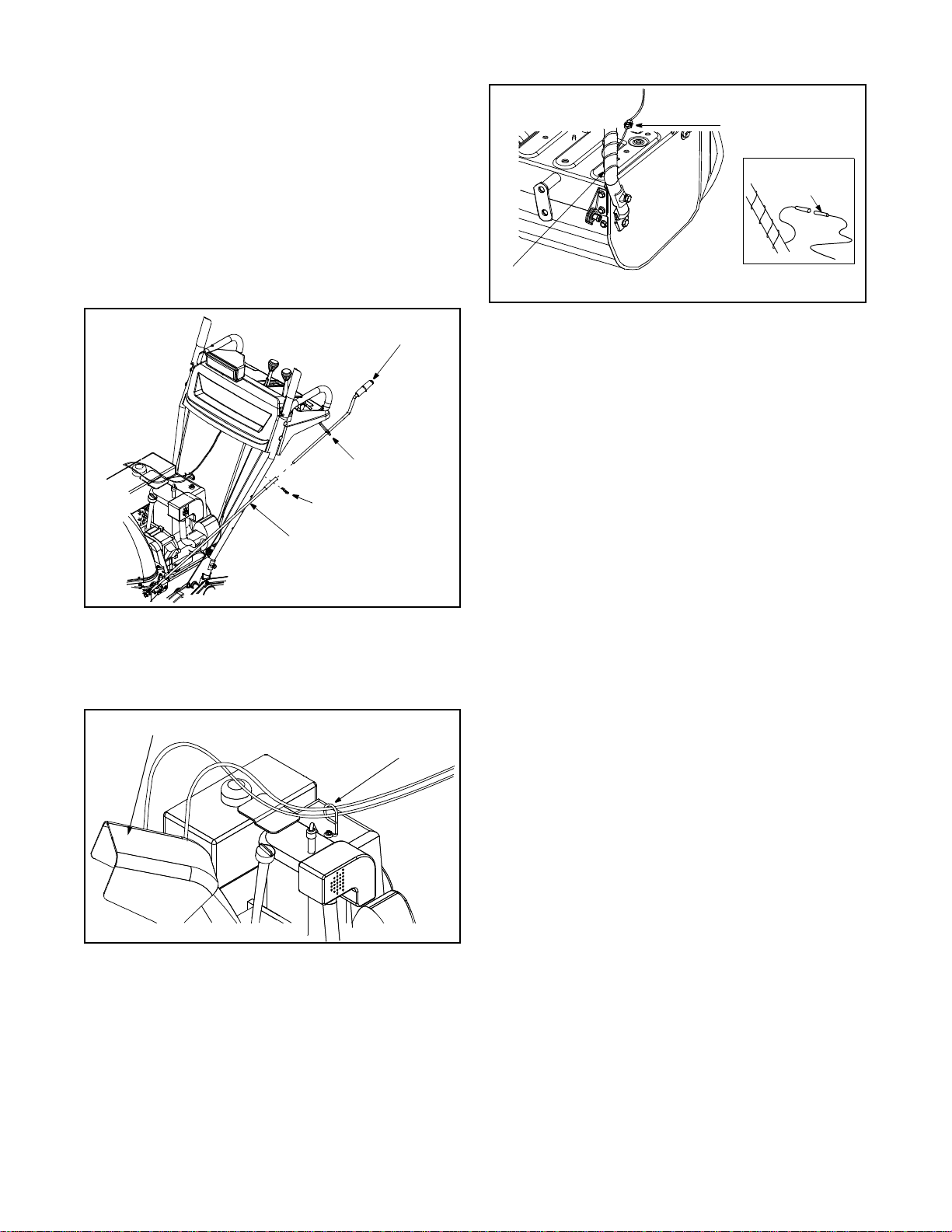
• If not already attached, slip the cables that run from
the handle panel to the discharge chute into the
cable guide located on top of the engine as shown
in Figure 5.
Discharge Chute
Cable Guide
Figure 5
• Unwrap the headlight wire which is attached to the
headlight, beneath the handle panel. Wind the
headlight wire around the lower right handle until
excess slack is removed. See Figure 6.
• Plug the wire from the headlight into the alternator
lead coming from the right side of the engine
underneath the fuel tank.
Alternator Lead
Alternator
Lead
Lamp Wire
(Wheels left out for clarity)
Figure 6
Final Adjustments
NOTE: It may be helpful t o read Section 3, Knowing
Your Snow Thrower, to help identify certain areas of the
snow thrower before performing adjustments.
Traction Control and Shift Lever
To check the adjustment of the traction control and shift
lever, proceed as follows:
• Move the shift lever into sixth (6) position.
• With the traction control released, push the snow
thrower forward, then pull it back. The machine
should move freely.
• Engage the traction control and attempt to move
the machine both forward and back, resistance
should be felt.
• Move the shift lever in to the f ast revers e (R2)
position and repeat the previous two steps.
If you experienced resistance rolling the unit, either
when repositioning the shift lever from 6 to R2 or when
attempting to move the machine with the traction
control released, adjust the traction control
immediately. To adjust, proceed as follows:
• Loosen the jam nut on the traction control cable
and UNTHREAD the cable one full turn.
• Recheck adjustment.
• Retighten the jam nut to secure the cable when
correct adjustment is reached.
NOTE: For more details, refer to Traction Control
Adjustment
Auger Control
Check the adjustment of the auger control as follows:
• Push down on the auger c ontro l unt il th e smal l
rubber bumper contacts the upper handle. There
should be a small amount of slack in the auger
control cable.
• Release the auger cont rol. The ca ble shoul d be
straight. Make certain you can depress the auger
control against the left handle completely.
If adjustment is necessary, proceed as follows:
6
Page 7
• Loosen the jam nut and thread the cable in (for less
slack) or out (for more slack) as necessary. See
Figure 7.
• Recheck adjustment; readjust as necessary and
tighten the jam nut.
“Z” End
Jam Nut
NOTE: Make certain the en tire bottom surface of skid
shoe is against the ground to avoid uneven wear on the
skid shoes.
High
Shave Plate
Low
Auger Control
Cable
Figure 7
Carriage Bolts
Skid
Shoes
Skid Shoes
The space between the shave plate and the ground can
be adjusted by repositioning the skid shoes. For close
snow removal, as when using on a smooth concrete or
asphalt driveway, place the skid shoes in the low
position. Use the middle or high position when the area
to be cleared is uneven. When operating on gravel,
always put skid shoes in the high position.
See Figure 8.
Adjust skid shoes as follows:
• Loosen, but do not remove, the three hex nuts
which fasten the skid shoe to the auger housing.
• Raise or lower the skid shoe to desired position.
• Retighten the hex nuts loosened earlier.
• Repeat on the other side of the snow thrower.
Tire Pressure (Pneumatic Tires)
The tires are overinflated for shipping purposes.
• Check tire pressure. Maintain pressure between 10
and 14 psi.
NOTE: If the tire pressure is not equal in both tires, the
unit may pull to one side or the other.
WARNING: Maximum tire pressure
under any circumstance is 30 psi. Equal
tire pressure should be maintained at all
times. Excessive pressure (over 30 psi)
when seating beads may cause tire/rim
assembly to burst with force sufficient to
cause serious injury.
SECTION 3: KNOWING YOUR SNOW THROWER
simultaneously with the traction control, the operator
WARNING: Read, understand, and
follow all instructions and warnings on
the machine and in this manual before
operating.
Traction Control / Auger Cont rol Lock
The traction control is located on the right handle.
Squeeze the traction control to engage the wheel drive.
Release to stop. See Figure 9.
This same lever also locks the auger control so you can
operate the chute crank without interrupting the snow
throwing process. If the auger control is engaged
can release the auger control (on the left handle) and
the augers will remain engaged. Release the traction
control to stop the augers and wheel drive (the auger
control must also be released).
IMPORT ANT :
changing speeds.
Auger Control
The auger control is located on the left handle.
Squeeze the auger control to engage the augers.
Release to stop the snow throwing action. The traction
control must also be released in order to stop the auger.
Hex Nuts
Figure 8
Always release the traction control before
7
Page 8

Shift Lever
The shift lever is located in the center of the handle
panel and is used to determine ground speed and
direction of travel. It can be moved into any of eight
positions. See Figure 9.
IMPORT ANT :
changing speeds.
Always release traction the control before
Forward
Your snow thrower has six forward (F) speeds. Position
number one (1) is the slowest and position number six
(6) is the fastest.
Reverse
Your snow thrower has two reverse (R) s peeds. R1 is
the slower, while R2 is the faster of the two.
Chute Crank
The chute crank is located on the left hand side of the
snow thrower. To change the direction in which snow is
thrown, turn the chute crank as follows:
• Turn clockwise to discharge to the left;
• Turn counterclockwise to discharge to the right.
• Operate the snow thrower in open areas until
becoming familiar with these controls.
Chute Tilt Contro l
The distance snow is thrown can be changed by
adjusting the angle of the chute assembly. Move the
chute tilt control forward to decrease the distance,
toward the rear to increase. See Figure 9.
Discharge Chut e
The angle of the discharge chute controls the distance
that the snow is thrown. Tilt the discharge chute up for
greater distance; tilt down for less distance.
Skid Shoe
The position of the skid shoe is determined by the
condition of the ground from where snow has to be
removed.
Headlight
The headlight is on whenever the engine is running.
Wheel Steering Controls
The left and right wheel steering controls are located on
the underside of the handles and are used to assist in
steering the snow thrower.
• Squeeze the right wheel steering control when
turning right; squeeze the left control when turning
left.
T raction Contro l /
Auger Control Lock
Headlight
Fuel Tank
Discharge
Chute
Throttle Control
The throttle control is located on the engine. It regulates
the speed of the engine. See Figure 9.
Safety Ignition Key
The safety ignition key must be fully inserted in the
switch before the unit will start. Remove key when snow
thrower is not in use. Do not attempt to turn the key.
See Figure 9.
Shift Lever
Auger Drive Control
Chute Tilt
Control
Chute Crank
Wheel St eer in g
Control
Primer
Choke
Electric
Starter
Button
Switch
Box
Auger
Skid Shoe
Figure 9
8
Safety
Ignition Key
Throttle
Control
Recoil
Starter
Handle
Page 9

SECTION 4: OPERATING YOUR SNOW THROWER
Before Starting
WARNING: Read, understand, and
follow all instructions and warnings on
the machine and in this manual before
operating.
Gas And Oil Fill-up
Service the engine with gasoline and oil as
instructed in the separate engine manual packed with
your snow thrower. Read instructions carefully.
WARNING: Use extreme care when
handling gasoline. Gasoline is extremely
flammable and the vapors are explosive.
Never fuel machine indoors or while the
engine is hot or running. Extinguish
cigarettes, cigars, pip es an o th er s our ces
of ignition.
• A plastic cap is provided inside the fuel fill opening
on the fuel tank. Remove and discard this cap
before filling up the tank. Use the separate fuel tank
cap to close after fill-up.
To Start Engine
NOTE: If unit shows any sign of motion (drive or
augers) with the clutch g rips disengaged, shut engine
off immediately. Readjust as instructed in the Final
Adjustments in the Assembly Section.
• Attach spark plug wire to spark plug. Make certain
the metal loop on end of the spark plug wire (inside
the boot) is fastened securely over the metal tip on
the spark plug.
• Make certain the auger and drive clutch levers are
in the disengaged (released) position.
• Move throttle control up to FAST position. Insert
ignition key into slot. See Figure 9. Be certain it
snaps into place. Do not turn key.
NOTE: Engine will not start unless ignition key is
inserted i nto ig nitio n slot in carb uretor cover .
Electric Starter
• Determine that your house wiring is a three-wire
grounded system. Ask a licensed electrician if you
are not certain.
WARNING: The electric starter is
equipped with a grounded three-wire
power cord and plug and is designed to
operate on 120 volt AC household
current. It must be used with a properly
grounded three-prong receptacle at all
times to avoid the possibility of electric
shock. Follow all instructions carefully
prior to operating the electric starter.
• If your house wiring system is not a three-wire
grounded system, do not use this electric starter
under any condi tions.
• If your home electrical system is grounded, but a
three-hole receptacle is not available, one should
be installed by a licensed electrician before using
the electr ic start er.
• If you have a grounded three-prong receptacle,
proceed as follows:
• Rotate choke knob to OFF position and do not
prime engine.
• Connect power cord to switch box on engine. Plug
the other end of power cord into a three-hole,
grounded 120 volt AC receptacle.
• Push starter button on top of the engine to crank
engine. As you crank the engine, move choke knob
to FULL choke position.
• When engine starts, release starter button, and
move choke gradually to OFF. If engine falters,
move choke immediately to FULL and then
gradually to OFF.
• When disconnecting the power cord, always unplug
from the three-prong receptacle first and then from
the snow thrower.
Recoil Starter
• Rotate choke knob to FULL choke position (cold
engine start). If engine is warm, place choke in OFF
position instead of FULL.
• Push primer button two or three times. If engine is
warm, pus h prim er but ton on ce on ly.
NOTE: Always cover v ent hol e in pr i mer bu tton when
pushing. Additional priming may be n ecessary for fir st
start if temp eratur e is below 15 °F.
• Grasp starter handle and pull rope out slowly, until
it pulls slightly harder. Let rope rewind slowly.
• Pull starter handle rapidly. Do not allow handle to
snap back. Allow it to rewind slowly while keeping a
firm hold on the starter handle.
• Repeat the previous steps until engine starts.
9
Page 10

To Stop Engine
• Run engine for a few minutes before stopping to
help dry off any moisture on the engine.
• To help prevent possible freeze-up of starter,
proceed as follows.
Electric Starter:
• Connect power cord to switch box on engine, then
to 120 volt AC receptacle. With the engine running,
push starter button and spin the starter for several
seconds. The unusual sound made by spinning the
starter will not harm engine or starter. Disconnect
the power cord from receptacle first, and then from
switch box.
Recoil Starter
• With engine running, pull starter rope with a rapid,
continuous full arm stroke three or four times.
Pulling the starter rope will produce a loud clattering
sound, which is not harmful to the engine or starter.
• Move throttle control to “stop” or “off” position.
• Remove ignition key. Do not turn key. Disconnect
the spark plug wire from the spark plug to prevent
accidental starting while equipment is unattended.
NOTE: Keep it in a safe place. Engine will not start
without ignition key.
Wipe all snow and moisture from the carburetor cover
in the area of the control levers. Also, move control
levers back and forth several times.
To Engage Wheel Drive
• With the engine running near top speed, move the
shift lever into one of the six FORWARD positions
or two REVERSE positions. Select a speed
appropriate for the snow conditions that exist.
NOTE: Use slower speeds in higher snow, and until
you are familiar with the operation of the snow thrower.
• Squeeze the traction control against the right
handle and the snow thrower will move. Release it
and the drive motion will stop.
IMPORT ANT :
releasing the traction control. Doing so will cause
premature wear to the drive system’s friction wheel.
NEVER move the shift lever without first
To Engage Augers
To engage the augers and start the snow throwing
action, proceed as follows:
• Squeeze the auger control against the left handle.
To disengage power to the augers:
• Release both the auger control and the traction
control, if engaged.
The auger control can be locked so you can turn the
electric chute directional control without interrupting the
snow thro wing pr oces s.
Operating Tips
NOTE: Allow the engine to warm up for a few minutes.
The engine will not develop full power until it reach es
operating temperature.
WARNING: The temperature of the muf-
fler and the surrounding areas may
°
exceed 150
• For the most efficient snow removal, remove snow
immediately after it falls.
• Discharge the snow downwind whenever possible.
• Slightly overlap each previous path.
• Set the skid shoes 1/4" below the shave plate for
normal usage. The skid shoes may be adjusted
upward (to lo wer the sh ave plat e) for har d-packe d
snow. Adjust downward (to raise the shave plate)
when using on gravel or crushed rock.
F. Avoid these areas.
SECTION 5: MAKING ADJUSTMENTS
WARNING: NEVER attempt to clean
chute or make any adjustments while
engine is running.
Traction Control
Refer to the information found under Final Adjustment
in the Assembly Section to adjust the traction control. If
you are uncertain that you have reached the correct
adjustment, proceed as follows:
WARNING: Drain the gasoline out of
your snow thrower’s engine, and place a
piece of plastic film under the gas cap to
avoid spillage before beginning the job.
• Tip the snow thrower forward, allowing it to rest on
the auger housing.
• Remove the frame cover underneath the snow
thrower by removing six self-tapping screws.
• With the traction control released, make sure there
is clearance between the friction wheel and the
drive plate in all positions of the shift lever.
• With the traction control lever engaged, make sure
the friction wheel solidly contacts the drive plate.
See Figure 10.
If adjustment is necessary, adjust traction control as
instructed below:
• Loosen the jam nut on the traction drive cable and
thread the cable in or out as necessary. Refer to
Figure 7.
10
Page 11

Shift Arm
Auger Actuator
Bracket
Trigger Cables
Drive Actuator
Bracket
necessary until the ferrule lines up with the upper
hole in the shift lever. See Figure 11.
• Insert ferrule from the left side of the snow thrower
into the upper hole.
• Reinstall the hairpin clip and the washer.
Hex Nut
And Cupped
Washer
Figure 10
• Retighten the jam nut to secure the cable when
correct adjustment is reached.
• Reassemble the frame cover.
NOTE: If you placed plas tic film unde r the gas cap, be
certain to remove it before operating the snow thrower.
Hex Gear Shaft
Rubber
Friction
Wheel
Drive Plate
Drive Wheels
The wheels may be adjusted for two different methods
of operation. The adjustment is made by placing the
click pins in one of two different holes on the right side
of the un it.
One Wheel Driving: Insert the click pin only through
the outsi de ho le of the a xle ( NOT th e rim ) on t he ri ght
side of the snow thrower. This position gives power
drive to the left wheel only, making the unit easier to
maneuver.
Both Wheels Driving: Insert the click pin through the
hole in the hub of the rim and the INSIDE hole on the
snow thrower’s right axle. This position is good for
heavy snow as there is power drive in both wheels.
IMPORT ANT :
click pin inserted through both the RIM and the
OUTSIDE HOLE in the axle. Doing so can result in
serious damage to the drive system.
NEVER operate the snow thrower with the
Shift Rod
To adjust the shift rod, proceed as follows:
• Remove the hairpin clip and flat washer from the
shift handle under the handle panel.
• Place shift le ver in sixth (6 ) positio n or fastes t
forward speed.
• Push shift arm as sembl y dow n as f ar as i t wil l go.
• Rotate the ferrule up or down on the shift rod as
IMPORT ANT :
adjustment of the shift rod as instructed under Final
Adjustments in the Assembly Section, before operating
the snow thrower.
Flat Washer
Shift Arm
Make certain to check for correct
Shift Lever
Hairpin Clip
Ferrule
Upper Shift Rod
Clutch Rod
Connector
Lower Shift Rod
Figure 11
Skid Shoe Adjustment
The space between the shave plate and the ground can
be adjusted by raising or lowering the skid shoes. Refer
to Skid Shoe Adjustment in the Assembly Section.
Auger Control Adjustment
Refer to the information found under Final
Adjustments in the Assembly Section to adjust the
auger control.
Chute Assembly
The distance snow is thrown can be adjusted by
adjusting the angle of the chute assembly. Refer to the
“Know Your Sn ow Throw er” secti on.
The remote chute control cables have been preadjusted at the factory. Move the remote chute lever on
the control panel back and forward to adjust angle of
the chute assembly.
11
Page 12

SECTION 6: MAINTAINING YOUR SNOW THROWER
WARNING: Before lubricating, repair-
ing, or inspecting, disengage all clutch
levers and stop engine. Wait until all moving parts have come to a complete stop.
Disconnect the spark plug wire and
ground it against the engine to prevent
unintended starting.
General Recommendations
• Always observe safety rules when performing any
maintenance.
• The warranty on this snow thrower does not cover
items that have been subjected to operator abuse
or negligence. To receive full value from the
warranty, operator must maintain the snow thrower
as instructed in this manual.
• Some adjustments will have to be made
periodically to maintain your unit properly.
• All adjustments in the service and adjustments
sections of this man ual shoul d be checke d at least
once each season.
• Follow the maintenance schedule given below.
• Periodically check all fasteners and hardware to
make sure t hese are t ight.
Vent Plug
Shear Bolts
Bearings
Figure 12
Discharge Chute
The base of the discharge chute and the spirals on the
chute crank should be lubricated at least every 25
hours of use. Apply the lubricant under the base of the
chute and where the spirals contact the discharge
chute. See Figure 13.
Carburetor
WARNING: If any adjustments are made
to the engine while the engine is running
(e.g. carburetor), keep clear of all moving
parts. Be careful of heated surfaces and
mufflers.
Minor carburetor adjustments may be required to
compensate for differences in fuel temperature, altitude
and load. Refer to the engine manual for instructions.
Lubrication
Gear Shaft
Lubricate the gear shaft with 6-in-1 grease (part
number 737-0170) at least once a season, or after
every 25 hours of operation. Refer to Figure 10.
IMPORT ANT :
friction wheel and drive plate.
Engine
Refer to the separate engine m anual p acked with yo ur
unit for all engine lubrication instructions.
Auger Shaft
• At least onc e a season , remove t he shear bo lts
from the auger shaft and spray lubricant inside the
shaft. See Figure 12.
Keep all grease and oil off the rubber
Lube Under Chute Base
Figure 13
Chute Crank Spirals
Drive and Shifting Mechanism
At least once a season or after every 25 hours of
operation, remove rear cover. Lubricate any chains,
sprockets, gears, bearings, shafts, and the shifting
mechanism at least once a season. Use engine oil or a
spray lubricant. Avoid getting oil on rubber friction
wheel and aluminum drive plate. Refer to Figure 10.
Gear Case
The gear case is lubricated with grease at the factory
and it does not require checking. If disassembled for
any reason, lubricate with 2 ounces of Shell Alvania
grease EPR00, part number 737-0168. Before
reassembling, remove old sealant and apply new
sealant. See Figure 12.
12
Page 13

IMPORT ANT :
damage to the seals could result. Be sure the vent plug
is free of grease in order to relieve pressure.
Do not overfill the gear case, since
Auger Bearings and Shaft
Every season lubricate the auger bearings and the
bearings on the side of the frame with light oil. See to
Figure 12.
Use oil or spray lubricant into the bearings at the
wheels at least once a season. Remove the wheels,
one side at a time, and clean and coat axles with multipurpose aut omotiv e grease.
Lubricate the auger shaft at least once a season. To do
this:
• Remove the shear bolts on the auger shaft.
• Oil or spray lubricant inside shaft.
• Carefully spin the auger around by hand to
disperse the lubricant.
• Reinstall the shear bolts.
Check Friction Wheel Rubber
Follow the instructions below to check the condition of
the friction wheel rubber every 25 hours of operation.
• Remove the six self-tapping screws from the frame
cover underneath the snow thrower.
• Visually inspect the friction wheel rubber for
excessive wear, cracks, or loose fit on the friction
wheel drive hub.
• Also engage the traction control and check if the
friction wheel is making contact with the friction
plate.
• If it does not make contact, adjust the traction drive
cable following instructions and recheck the friction
wheel.
• Replace friction wheel rubber if necessary. Refer to
instructions in Service Section.
Check V-Belts
Follow the instru ction s bel ow to c heck t he cond itio n of
the drive belts every 50 hours of operation.
• Remove the plastic belt cover on the front of the
engine by removing the three self-tapping screws.
• Visually inspect for frayed, cracked, or excessively
worn out belts.
• Replace belts as necessary as outlined in Service
Section.
Traction Cont rol / Auger Co ntrol Lock
The cams on the ends of the control rods which
interlock the traction drive and auger drive clutches
must be lubricated at least once a season or every 25
hours of operation using a multi-purpose automotive
grease. The cams can be accessed beneath the handle
panel. See Figure 14.
Handle Panel
Control Rods
Lube Cams Here
Figure 14
SECTION 7: SERVICING YOUR SNOW THROWER
WARNING: Before servicing, r epairing,
or inspecting, disengage all clutch levers
and stop engine. Wait until all moving
parts have come to a complete stop.
Disconnect spark plug wire and ground it
against the engine to prevent unintended
starting.
Augers
The augers are secured to the spiral shaft with two
shear bolts and hex lock nuts. If you hit a foreign object
or ice jam, the snow thrower is designed so that the
bolts may shear. See Figure 15.
If the augers do not turn, check if the bolts have
sheared. Two replacement shear bolts and hex lock
nuts have been provided with the snow thrower. Refer
to Loose Part s in th e Assemb ly Secti on.
IMPORT ANT :
standard hex bolts. Any damage to the auger gearbox
or other components, as a result of doing so, will NOT
be covered by your snow thrower’s warranty.
Shave Plate and Skid Shoes
The shave plate and skid shoes on the bottom of the
snow thrower are subject to wear. They should be
checked periodically and replaced when necessary.
NOTE: The skid shoes on this mac hine have two wear
edges. When one s ide wears out, they can be rot ated
180° to use the other edge.
13
NEVER replace the auger shear bolts with
Page 14

Shear Bolts
Hairpin
Clip
Flat
Washe rs
Belt Cov er Bolts(3)
Belt Cover
Washer
Hex Nut
Carriage Bolt
Shave Plate
Figure 15
• Remove the six carr iage bolts (three per si de),
belleville washers and hex nuts which attach slide
shoes to the snow thrower on two sides. See Figure 8.
• Reassemble new slide shoes with the hardware
removed earlier (cupped side of belleville washer
against the slide shoes). Make certain the slide
shoes are adjusted to be level.
• To remove the shave plate, remove slide shoe as
well as the carriage bolts, belleville washers and
hex nuts which attach shave plate to the snow
thrower housing. For location of shave plate and
carriage bolts, see Figure 15.
• Reassemble the new shave plate, making sure
heads of carriage bolts are to the inside of the
housing.
• Reinstall the skid shoes and tighten securely.
Replacing Belts
To remove and replace either the auger belt or the drive
belt, follow the steps below and then proceed to the
specific steps listed under respective sub-headings.
• Disconnect the chute crank assembly at the
discharge chute end by removing the hairpin clip
and the two flat washers.
• Remove the plastic belt cover, located near the
engine, by removing the three self-tapping screws
and flat washers that secure it. See Figure 16.
• Remove the larg e shoulder bolt and wa sher on the
left hand side of the engine pulley. See Figure 16.
Upper Bolt
Shoulde r B olt
(do not remove)
Engine Pulley
Shoulde r Bo lt
(remove)
Figure 16
Auger Belt
• Remove the cott er pin and washer from t he ferrul e
in order to disconnect the auger idler rod from the
brake bracket assembly. See Figure 17.
• Slip the auger control belt (the front belt) off the
engine pulley.
Engine
Pulley
Auger Idler
Rod
Auger Control
Belt
Brake Bracket
Assembly
14
Ferrule
Z Fitting
Cable Roller
Guide
Figure 17
Page 15

• Pull the brake bracket assembly towards the cable
guide roller and unhook the auger cable “Z” fitting.
• Remove the upper bolts and lock washers which
attach the auger housing assembly to the frame
assembly using a 9/16” wrench. See Figure 16.
• Separate the auger housing from the frame
assembly by tilting the housing forward and pulling
up the handles.
• Using a 1/2” wrench, remove the hex screw and
belleville washer from the center of the pulley on
the auger housing. Lift the brake bracket assembly
out of the pulley groove and remove the pulley. Be
careful not to lose the key. See Figure 18.
Brake Bracket Assembly
Belt Keepers
Auger Belt
Idler Pu lley
Auger Pulley
Hex Screw
Bellevi lle Washer
Figure 18
• Remove and replace auger belt inside belt keepers.
• Reassemble pulley to auger housing with hex
screw and belleville washer (cupped side toward
the pulley). Make sure key is in place on shaft and
brake puck is seated in the pulley groove.
• Reassemble the belt cover and chute directional
control.
Proper Adjustment: With the auger clutch lever in the
disengaged position the top surface of the new belt
should be even with the outside diameter of the pulley.
• To adjust, disconnect fer rule from brake brac ket
assembly and thread ferr ule in (towards idler) to
increase tension on belt, and out to decrease tension.
NOTE: The brake puck must always be f ir ml y se at e d i n
the pulley groove when the auger control is in the
disengaged position.
Drive Belt
• Unhook the extension spring from the belt cover
plate. See Figure 19.
• Remove drive belt from the engine pulley and
bottom drive pulley. Refer to Figure 19.
• Replace belt and reassemble in reverse order.
• Reassemble the two halv es of the un it hooki ng the
lower portion of the auger housing over the
stationary shoulder bolts in the frame assembly.
Belt Cover
Extension
Spring
Drive Belt
Figure 19
• Secure the two ha lves w ith t he tw o bol ts and lock
washers removed earlie r. Refer to Figure 16.
• Attach the “Z” fitting of the cable into the brake
bracket assembly. Refer to Figure 17.
• Slip the auger control belt over engine pulley.
• Insert ferrule on auger idler rod into bracket
assembly and secure with flat washer and cotter
pin. Reassemble the large shoulder bolt and lock
washer as shown in Figure 16.
• Reassemble belt cover and chute crank.
Changing Friction Wheel Rubber
The rubber on the friction wheel is subject to wear and
should be checked after the first 25 hours of operation,
and periodically thereafter. Replace the friction wheel
rubber if any signs of wear or cracking are found.
• Drain the gasoline from the snow thrower, or place
a piece of plas tic under the gas cap.
• Tip the snow thrower up and forward, so that it rests
on the housing.
• Remove six screws from the frame cover
underneath the snow thrower. Refer to Figure 10.
• Remove the left wheel from the axle.
• Using a 7/8” wrench, hold the hex shaft and remove
the hex bolts and cupped washer and bearing from
left side of the frame. See Figure 20.
• Holding the friction wheel assembly, slide the hex
shaft out of the left side of the unit. The spacer on
the right side of the hex shaft will fall and the
sprocket should remain hanging lose in the chain.
• Lift the friction wheel assembly out between the
axle shaft and the drive shaft assemblies.
• Remove the six screws from both sides of the
friction wheel assembly and remove friction wheel
rubber from between the friction wheel plate.
See Figure 20.
15
Page 16

Shift Arm Assem b l y
Shift Arm
Assembly
Friction
Wheel
Friction W heel
Pin
Pin
Sprocket
Spacer
Sprocket
Spacer
• Insert the pin from the shift arm assembly into the
friction wheel assembly and hold assembly in
position. See Figure 20.
• Slide the hex shaft through the left side of the
housing and through the friction wheel assembly.
• Insert the hex shaft through the sprocket and the
spacer. Make certain that the chain engages both
the large and the small sprocket.
NOTE: If the sprocket fe ll from the snow th rower while
removing the hex shaft, place the sprocket on the hex
shaft. Position the hex hub of the sprocket toward the
friction wheel when s liding the sprocket on to the hex
shaft. See Figure 21.
Friction Wheel Plates
Bearing
Screws
Friction Wheel
Rubber
Hub
Figure 20
• Reassemble the new friction wheel rubber to the
friction wheel assembly, tightening the six screws in
rotation and with equal force. It is important to
assemble the rubber on the friction wheel
symmetrically for proper functioning.
Shift Arm
Assembly
Hex Shaft
Hex Hub
Of Sprocket
Friction
Wheel
Sprocket
Sprocket
Pin
Spacer
Spacer
Figure 21
• Secure with the bell washer and hex bolt removed
earlier.
• Secure the frame cover with six self-tapping
screws. Put the snow thrower down to its normal
operating position.
NOTE: If you placed plas tic film unde r the gas ca p, be
certain to remove it.
Engine
Refer to separate engine manual for all engine
maintenance procedures.
SECTION 8: OFF-SEASON STORAGE
WARNING: Never store engine with fuel in
tank indoors or in poorly ventilated areas,
where fuel fumes may reach a n open flame,
spark or pilot light as on a furnace, water
heater, clothes dryer or other gas appliance.
• If unit is to be stored over 30 days, prepare engine
for storage as instructed in the engine manual.
• Remove all debris from the exterior of equipment.
• Follow lubrication recommendations on page 12.
• Always store the snow thrower in a clean, dry area.
NOTE: When storing any type of power equipment in
an unventilated or metal sto rage shed, care shou ld be
taken to rust proof the equipment. Using a ligh t oil or
silicone, coat the equipment, especially any chains,
springs, bearings and cables.
16
Page 17

SECTION 9: TROUBLESHOOTING
Problem Cause Remedy
Engine fails to star t. 1. Fuel tank empty, o r stale fuel.
2. Blocked fuel lin e.
3. Choke not in ON p osition
4. Faulty spark plug.
5. Safety key not in i gnition sw itch on eng ine.
6. Spark plug wire disconnect ed.
7. Primer button not being used properly.
Engine runs erratic. 1. Unit running on CHOKE.
2. Blocked fuel lin e or stal e fuel.
3. Water or dirt in fue l system.
4. Carburetor out of adjustment.
Loss of power. 1. Spark plug wire loose.
2. Gas cap vent hole plugged.
3. Exhaust port plugged .
Engine overheats. 1. Carburetor not adjus ted proper ly. 1. Refer to the engine manual or have th e
Excessive vibration . 1. Loose parts or da maged au ger. 1. Stop engine imme diately and disc onnect
Unit fail s
to propel itself.
Unit fail s
to discharge snow.
1. Traction contr ol cable in need of adjust ment.
2. Drive belt loose or damage d.
1. Discharge chute clogg ed.
2. Foreign object lodged in auger.
3. Auger control cable in need of adjustm ent.
4. Auger belt loose or damaged.
5. Shear bolt(s) sheared.
NOTE: For repairs beyond the minor adjustments listed above, contact the local dealer.
1. Fill tank with fresh gasoline.
2. Clean the fuel line.
3. Move switch to ON position
4. Clean, adjust gap or replac e.
5. Insert the key fully into the switch.
6. Connect spark plug wire.
7. Refer to the engine manu al.
1. Move choke lever to OFF position.
2. Clean fuel line a nd fill ta nk with c lean, fres h
gasoline.
3. Drain fuel tank an d carburetor. R efill wi th
fresh fuel.
4. Refer to the engine manu al.
1. Connect and tighten spark plug wire.
2. Remove ice and snow from gas cap. Be
certain vent hole is clear.
3. Refer to the engine manu al.
carburetor adjusted b y an aut horized
engine service deale r.
spark plug wire. Tighten all bolts and nuts. If
vibration continues, have unit serviced by
an authorized se rvice de aler.
1. Adjust traction c ontrol cab le. Refer to
Adjustments.
2. Replace drive belt.
1. Stop engine imme diately and disc onnect
spark plug wir e. Clean discharge chute and
inside of auger housing.
2. Stop engine imme diately and disc onnect
spark plug wir e. Remo ve objec t from au ger.
3. Refer to Final Adjus tments i n Assembly
Section.
4. Refer to Adjustments.
5. Replace shear bolt(s).
17
Page 18

Model 31AE993I401
45
42
7
44
40
8
25
8
25
25
3
50
13
17
27
13
18
26
34
8
25
5
55
14
54
47
43
16
14
21
31
14
21
1
48
56
53
22
25
14
13
51
5
33
9
34
26
32
52
38
36
15
2
28
20
46
6
24
29
30
23
10
39
37
13
49
29
11
35
12
41
5
19
25
14
13
4
25
18
Page 19

Model 31AE993I401
Ref.
No.
1. 05244A Bearing Housing
2. 618-0281A Bracket Assembly: Auger Break
3. 684-0090A Impeller Assembly : 16”
4. 710-0371 Hex Lock Bolt 5/1 6-18 x .8 75”
5. 710-0451 Carriage Bolt 5/16-1 8 x .750”
6. 710-0459A Hex Screw, Special 3/8-24 x 1.5 ”
7. 710-0528 Hex Screw 5/16-18 x 1.25”
8. 710-0604A Self-Tapp. Screw 5/16 -18 x .62 5”
9. 710-0891 Shear Bolt 5/16-18 x 1.75 ”
10. 711-0640 Stud
11. 711-0677 Ferrule
12. 712-011 6 Jam Nut 3/8-24
13. 712-042 9 Hex Lock Nut 5/16-18
14. 712-3010 Hex Nut 5/16-18
15. 714-010 4 Hairpin Clip
16. 714-0126 Key
17. 714-0135 Key
18. 715-011 8 Spiral Pin
19. 731-1696 Chute Adapter
20. 732-085 8 Extension Spri ng
21. 736-011 9 Lock Washer
22. 736-015 9 5/16 Washer
23. 736-016 9 Lock Washer
24. 736-017 4 Wave Washer
25. 736-024 2 Beleville Washer
26. 736-025 0 Flat Washe r
27. 736-027 1 Spring Washer
28. 736-300 8 Flat Washe r
Part No. Part Description
Ref.
No.
30. 738-0281 Shoulde r Screw
31. 741-0185 Self-Alig ning Beari ng
32. 741-0192 Flange Bearing w / Flats
33. 741-0475 Plastic Bushing
34. 741-0494 Flange Bushing
35. 747-0980 Idler Rod : Auger
36. 754-0222 V-Belt
37. 756-0178 Flat Id ler
38. 756-0243 Pulley
39. 784-0385A Idler Bra cket: Auger
40. 784-5076 Support Brac ket
41. 784-5123 Chute Crank Bracket
42. 784-5710 Support Plate
43. 784-5711 Chute Bracket
44. 618-0436 Gear Assembly
45. 705-5210A Spiral Assembly RH
46. 705-5211A Spiral Assembly LH
47. 684-0093A Auger Housing Assembly
48. 784-5697 Slide Shoe
49. 737-3000 Lube Fitting
50. 738-0491 Spiral Axle
51. 736-0105 Bell Washer
52. 784-0315 Bearing Housing
53. 784-5714 Shave Plate
54. 710-0389 Carriage Screw
55. 710-3168 Carriage Bolt
56. 712-0798 Hex Nut 3/8-16
Part No. Part Description
NOTE: For painted parts, please ref er to
the list of color codes below. Please add
the applicable color code, wherever
needed, to the part number to order a
replacement part. For instance, if a part
numbered 700-sextets is painted YardMan Green, the part number to order
would be 700-sextets-0665.
Yard-Man Green: 0665
Yard-Man Yellow: 0674
Powder Black: 0637
19
Page 20

Model 31AE993I401
18
28
44
78
16
70
79
19
43
12
23
33
49
42
18
45
55
46
36
45
55
60
8
35
35
32
6
14
51
22
64
21
55
52
37
17
76
9
50
26
62
61
38
47
55
53 69
55
57
20
68
40
30
60
46
33
29
41
46
13
77
48
15
47
1
31
31
56
65
20
7
59
46
22
16
4
11
66
5
54
39
56
2
29
13
56
45
3
34
73
58
67
71
45
27
24
47
63
75
18
42
51
30
10
19
66
27
31
43
62
31
55
61
48
15
50
26
77
18
18
20
79
78
Page 21

Model 31AE993I401
Ref.
No.
1. 05523 Support Bracket: Pivot
2. 618-0278 Bush Assembly
3. 618-0279 Dogg Assembly LH
4. 618-0280 Dogg Assembly RH
5. 618-0282B Shift Assembly
6. 618-0296 Wheel Bearing Assembly
7. 684-0115 Support Bracket Assembly
8. 684-0116 Shift Arm Assembly
9. 684-0117 Shift Rod Assembly
10. 684-0118 Auger Actuator Bracket Assy.
11. 684-0119 Drive Actuator Br acket Assy .
12. 684-0120 Frame Assembly
13. 684-0122 Sprocket Assemb ly
14. 710-0195 Hex Screw1/4-28 x .625”
15. 710-0538 Hex Screw5/16-18 x .625”
16. 710-0599 TT Screw 1/4-20 x .5”
17. 710-0788 TT Screw 1/4-20 x 1”
18. 710-1652 TT Screw1/4-20 x .625”
19. 710-3001 Hex Screw 3/8-16 x .880”
20. 710-3008 Hex Screw 5/16-18 x .7 5”
21. 710-3103 Hex Screw 5/16-18 x 2”
22. 710-3180 Hex Screw 5/16-18 x 1.75”
23. 711-1191 Hex Shaft: Drive
24. 711-1193 Actuator Shaft
25. 711-1194 Actuator Drive Shaft
26. 712-0116 Lock Nut
27. 712-0138 Hex Nut 1/4-28
28. 712-0221 Jam Lock Nut
29. 712-0429 Hex Lock Nut
30. 712-0798 Hex Nut 3/8-16
31. 712-3010 Hex Nut 5/16-18
32. 713-0284 Chain
33. 713-0286 Chain
34. 713-0413 Sprocket
35. 714-0101 Hairpin Clip
36. 714-0104 Hairpin Clip
37. 714-0115 Cotter Pin
38. 714-0388 Key
39. 715-0249 Roll Pin
40. 717-0302 Drive Plate
Part No. Part Description
Ref.
No.
41. 732-0121 Extension Spring
42. 732-0209 Extension Spring
43. 736-0119 Lock Washer 5/16
44. 736-0158 Lock Washer 5/8
45. 736-0160 Flat Washer
46. 736-0163 Flat Washer
47. 736-0217 Lock Washer
48. 736-0242 Beleville Washer
49. 736-0275 Flat Washer
50. 736-0300 Flat Washer
51. 736-0329 Lock Washer
52. 736-0623 Flat Washer
53. 736-0639 Flat Washer
54. 737-0170 Lubricant
55. 737-3007 Grease
56. 738-0143 Shoulder Screw
57. 738-0279 Spindle: Drive Plate
58. 738-0924 Shoulder Screw 1/4-28 x .375”
59. 741-0163A Bearing Housing Assembly
60. 741-0192 Flange Bearing
61. 741-0563 Ball Bearing
62. 741-1111 Hex Flange Bearing
63. 746-0949 Steer Cable
64. 746-0951 Idler Cable: Auger
65. 747-0973 Clutch Rod: Drive
66. 750-0903 Split Spacer
67. 750-0997 Spacer
68. 750-1097 Split Spacer
69. 750-1196 Spacer
70. 756-0344 Drive Pulley
71. 756-0625 Roller Cable
72. 784-0377 Frame Support Bracket
73. 784-0379 Frame Cover: Upper
74. 784-0380 Frame Cover: Lower
75. 784-0384 Auger Cable Bracket
76. 784-5590 Bracket: Shift — Frame
77. 738-0975 Axle: Wheel
78. 714-0151A Klik Pin
79. 734-1593 Wheel
Part No. Part Description
21
Page 22

Model 31AE993I401
36
34
37
35
17
33
19
A
21
15
1
23
21
26
4
13
15
19
40
10
31
30
5
9
27
13
34
22
21
11
1
42
38
44
11
22
7
41
24
3
A
6
A
9
35
28
32
33
25
A
32
6
29
7
5
19
19
4
23
15
39
43
18
16
12
8
20
15
22
2
14
Page 23

Model 31AE993I401
Ref.
No.
1. 646-0012 Cable Assembly: Auger/Drive
2. 684-0053B Chute Crank Assembly
3. 705-5266 Chute Crank Bracket
4. 710-3119 Hex Screw 3/8-16 x .75”
5. 710-1878 Hex Screw3/8-16 x 1.75”
6. 710-0458 Carriage Bolt 5/16-18 x 1.75”
7. 710-0572 Carriage Bolt 5/16-18 x 2.5”
8. 710-0891 Shear Bolt 5/16-18 x 1.75”
9. 710-3015 Hex Screw 1/4-20 x .75”
10. 711-0677 Ferrule
11. 712-0287 Hex Nut 1/4-20
12. 712-0429 Hex Lock Nut
13. 712-3010 Hex Nut
14. 714-0101 Hairpin Clip
15. 714-0104 Hairpin Clip
16. 720-0201A Chute Crank Knob
17. 720-0284 Knob
18. 726-0100 Push Cap
19. 736-0105 Bell Washer
20. 736-0185 Flat Washer
21. 736-0242 Beleville Washer
22. 736-0270 Bell Washer
23. 736-0275 Flat Washer
24. 741-0475 Plastic Bushing
25. 747-0624 Chute Crank
26. 747-0983 Lower Shift Rod
27. 747-0997 Upper Shift Rod
Part No. Part Description
Ref.
No.
28. 749-0989A Upper Handle LH
29. 749-0990A Upper Handle RH
30. 749-0991 Lower Handle
31. 750-0963 Clutch Rod Connector
32. 710-1625 Oval C-Sunk Screw
33. 712-0127 Flat Weld Nut
34. 725-0157 Cable Tie
35. 746-0950 Trigger Control
36. 625-0007 Light Assembly
37. 705-5218 Handle Engagement RH
38. 705-5219 Handle Engagement LH
39. 710-1003 Special B Screw
40. 712-0271 Hex Sems Nut
41. 712-0429 Hex Lock Nut
42. 720-0232 Shift Knob
43. 731-0061 Handle Panel
44. 736-0159 5/16 Washer
Part No. Part Description
725-1658 Halogen La mp
725-1672 Lens Assemb ly
777D00133 Label: Front Handle Panel
777D00179 Label: Yard Man Sides
777D05319 Label: Auger 13/33
777I20412 Label: Panel Steeri ng RH
777I20747 Label: Panel Steeri ng LH
777S30511 L abel: Chute Dange r
777S30514 L abel: Housing Da nger
NOTE: For painted parts, please ref er to
the list of color codes below. Please add
the applicable color code, wherever
needed, to the part number to order a
replacement part. For instance, if a part
numbered 700-sextets is painted YardMan Green, the part number to order
would be 700-sextets-0665.
Yard-Man Green: 0665
Yard-Man Yellow: 0674
Powder Black: 0637
23
Page 24

Model 31AE993I401
6
15
18
14
22
12
10
23
24
25
15
6
14
8
26
7
21
1
13
3
3
20
9
19
17
4
11
13
5
2
Ref.
No.
1. 07386 Washer
2. 684-0123A Belt Cover Bracket Assembly
3. 710-0191 Hex Screw 3/8-24 x 1.25”
4. 710-0237 Hex Screw 5/16-24 x .625”
5. 710-0502A TT Sems Screw
6. 710-0607 TT Screw 5/16-18 x 0.5”
7. 710-1245 Hex Lock Screw 5/16-24 x .875”
8. 712-0116 Jam Nut
9. 714-0118 Key
10. 731- 2531 Be lt Cover
11. 732-0303 Extension Spring
12. 736- 0159 5/16 Washer
13. 736-0217 Lock Washer
14. 736-0242 Beleville Washer
15. 736- 0264 Fla t Washer
17. 738- 0215A Shoulder Screw
18. 748- 0234 Shoulder Spacer
19. 754-0131 V-Belt
20. 756- 0240 Fla t Idler
21. 756- 0241B Double Pulley
22. 784-5726 Idler Bracket
23. 712- 0324 Hex Lock Nu t: 1/4-20
24. 732-0705 Cable Guide
25. 736- 0173 Fla t Washer
26. 629-0071 Extension Cord: 110V, 3-prong
Part No. Description
24
Page 25

Model 31AE993I401
12
34
8
21
36
13
26
17
27
37
22
35
38
34
26
22
32
30
6
26
6
33
3
11
7
33
29
22
23
30
6
20
28
24
4
15
25
31
6
19
10
16
6
18
10
14
2
4
1
Ref.
No.
1. 710-0276 Carriage Screw
2. 710-0458 Carriage Bolt 5/1 6-18 x 1.7 5”
3. 710-0805 Hex Bolt 5/16-18 x 1.5 ”
4. 710-0896 Hex AB Screw 1/4-14 x .625 ”
5. 710-3015 Hex Screw 1/4-20 x .75”
6. 712-0429 Hex Lock Nu t
7. 712-3027 Hex Flange Lock Nut
8. 731-0846C Up per Chute
9. 731-0851A Chute Flange Keeper
10. 731-1313C Cable Guide: Chute Tilt
11. 731-0903D Lower Chute
12. 784-5680 Handle Suppt. Brac ket 5/8 RH
13. 736-0159 5/16 Washer
14. 736-0231 Flat Washer
15. 736-0506 Special Washe r
16. 746-0902 Chute Control Cabl e
17. 746-0903 Chute Cable w/Clip
18. 784-5594 Cable Bracket
19. 784-5604 Chute Tilt Handle
20. 684-01 02 Handle Panel Assembly w/ Tilt
21. 710-0459A Hex Bolt 3/8-24 x 1.5”
22. 710-0599 TT Screw 1/4-20 x 0.5”
23. 711-0653 Clevis Pin
24. 712-0116 Jam Nut
25. 784-5682 Handle Suppt. Brac ket 3/8 RH
26. 714-0104 Cotter Pin
27. 732-0145 Spring
28. 732-0193 Spring
29. 732-0746 Torsion Spring
30. 735-0199A Rubber Bumper
31. 736-0105 Bell Washer
32. 784-5681 Handle Suppt. Brac ket 3/8 LH
33. 736-0509 Special Washe r
34. 747-0877 Cam Rod
35. 748-0362 Cam: Handle Lock
36. 748-0363 Pawl: Handle Loc k
37. 784-5619A Shift Handle
38. 784-5679 Handle Suppt. Brac ket 5/8 LH
Part No. Description
9
5
25
Page 26

Notes
26
Page 27

27
Page 28

MANUFACTURER’S LIMITED WARRANTY FOR:
The limited warranty set forth below is given by MTD
PRODUCTS INC (“MTD”) with respect to new mercha ndise
purchased and used in the United States, its possessions
and territories.
MTD warrants this product against defects in material and
workmanship for a period of two (2) years commencing on
the date of original purc ha se an d w i ll, at its option, repai r or
replace, free of charge, any part found to be defective in
material or workmanship. This limited warranty shal l only
apply if this product has been operated and maintained in
accordance with the Operator’s Manual furnished with the
product, a nd has not bee n subj ect to misuse, abuse, commercial use, neglect, accident, improper maintenance,
alteration, vandalism, theft, fire, water or damage because
of other peril or natur al di sa ste r. Damage resulting from the
installation or use of any accessory or attachment not
approved by MTD Products Inc. for use with the product(s)
covered by this manual will void your warranty as to any
resulting damages.
Normal wear parts or components thereof are subject to
separate terms as follows: All normal wear part or component failures will be covered on the product for a period of
90 days regardless of cause. After 90 days, but within the
two year period, normal wear part failures will be covered
ONLY IF caused by defects in material or workmanship of
OTHER component parts. Normal wear parts and components include, but are not limited to, belts, blades, blade
adapters, grass bags, rider deck wheels, seats, snow
thrower skid shoes, shave plates and tires. Batteries are
covered by a 90-day limited replacement warranty.
HOW T O OBTAIN SERVICE: W arr anty service is a v aila b le ,
WITH PROOF OF PURCHASE THROUGH YOUR LOCAL
AUTHORIZED SERVICE DEALER. To locate the dealer in
your area, please check for a listing in the Yellow Pages or
contact the Customer Service Department of MTD PRODUCTS INC by calling 1-800-800-7310 or writing to P.O. Box
368022, Clev e land, Ohio 44136-9722.
This limited warranty does not provide coverage in the
following cases:
a.The engine or component parts thereof. These items
carry a separate manufacturer’s warranty. Please refer
to the applicable manufacturer’s warranty on these
items.
b.Log splitter pumps, valves and cylinders have a sepa-
rate one year warr an ty.
c. Routine maintenance items such as lubricants, filters,
blade sharpening and tune-ups, or adjustments such
as brake adjustments, clutch adjustments or deck
adjustments; and normal deterioration of the ex terior
finish due to use or exposure.
d. MTD does not extend any warranty for products sold
or exported outside of the United States of America,
its possessions and territories, except those sold
through MTD’s authorized channels of export distribu-
tion.
No implied warranty, including any implied warranty of
merchantability or fitness for a particular purpose,
applies after the applicable period of express written
warranty above as to the par ts as ident ified. No o ther
express war ranty or guaranty, whether wri tten or or al,
except as mentioned above, given by any person or
entity, including a dealer or retailer, with respect to any
product shall bind MTD. During the period of the Warranty, the exclusive remedy is repair or replacement of
the product as set forth above. (Some states do not
allow limitations on how long an implied warranty lasts, so
the above limitation may not apply to you.)
The provisions as set f orth in this W a rranty pr o vide the
sole and exclusive remedy arising from the sales. MTD
shall not be liable for incidental or consequential loss
or damages including, without limitation, expenses
incurred for substitute or replacement lawn care services, for transportation or for related expenses, or for
rental expenses to temporarily replace a warranted
product. (Some states do not allow the exclusion or limita-
tion of incidental or consequential damages, so the above
exclusion or limitation may not apply to you.)
In no event shall recover y of any kind be greater than the
amount of the purchase price o f the pro duct sold . Alter ati on
of the safety features of the product shall void this Warranty. You assume the risk and liability for loss, damage, or
injury to you and your property and/or to others and their
property arising out of the use or misuse or inability to use
the product.
This limited warranty shall not extend to anyone other than
the original purchaser, original lessee or the person for
whom it was purchased as a gift.
How State Law Relates to this Warranty: This limited
warranty gives you specific legal rights, and you may also
have other rights which vary from state to stat e.
28
 Loading...