

Page 1
Safety ° Assembly ° Operation ° Adjustments ° Maintenance °Troubleshooting ° Parts Lists ° Warranty
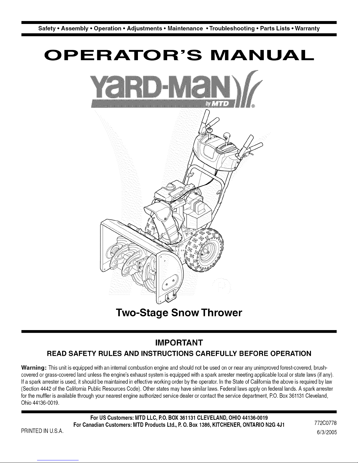
O P RA-rO R'S MANUAL
Two-Stage Snow Thrower
READ SAFETY RULES AND INSTRUCTIONS CAREFULLY BEFORE OPERATION
Warning: Thisunitisequippedwithaninternalcombustionengineandshouldnotbeusedon ornearanyunimprovedforest-covered,brush-
coveredor grass-coveredlandunlesstheengine'sexhaustsystemisequippedwitha sparkattestermeetingapplicablelocalor statelaws(if any),
If a sparkarresterisused,it shouldbemaintainedineffectiveworkingorderby the operator,IntheStateof Californiatheaboveisrequiredbylaw
(Section4442oftheCaliforniaPublicResourcesCode),Otherstatesmayhavesimilarlaws,Federallawsapplyonfederallands,A sparkattester
forthemufflerisavailablethroughyournearestengineauthorizedservicedealeror contacttheservicedepartment,P.O,Box361131Cleveland,
Ohio44136-0019,
ForUSCustomers: MTDLLC,P.O.BOX361131CLEVELAND,OHIO44136-0019
ForCanadianCustomers:MTD ProductsLtd.,P.O.Box1386,KITCHENER,ONTARION2G4J1
PRINTEDIN U,S,A,
IMPORTANT
772C0778
6/3/2005
Page 2
This Operator's Manual is an important part of your new snow thrower. It will help you assemble,
prepare and maintain the unit for best performance. Please read and understand what it says.
Table of Contents
Safety Labels ...................................................... 3
Safe Operation Practices ................................... 4
Setting Up Your Snow Thrower .......................... 6
Operating Your Snow Thrower ......................... 10
MakingAdjustments ......................................... 14
Finding and Recording Model Number
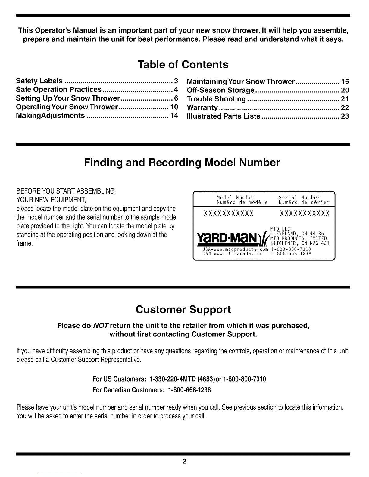
BEFOREYOU STARTASSEMBLING
YOURNEW EQUIPMENT,
please locatethe modelplate onthe equipmentand copythe
themodel number andthe serial numberto the sample model
plate providedto the right.You can locatethe modelplate by
standing atthe operatingposition and looking down atthe
frame.
Maintaining Your Snow Thrower ...................... 16
Off-Season Storage .......................................... 20
Trouble Shooting .............................................. 21
Warranty ............................................................ 22
Illustrated Parts Lists ....................................... 23
Model Number Serial Number
Num6ro de mod61e Num6ro de s6rier
XXXXXXXXXXX XXXXXXXXXXX
•,,A .... m,,,.\f CLEVELAND, OH 44136
MTD LLC
Y_IIHUIMZrIN_//MTD PRODUCTS LIMITED
........... UL KITCHENER, ON N2G 4Jl
USA-www.mtdproducts.com 1-800-800-7310
CAN-www.mtdcanada. com 1-800-668-1238
Customer Support
Please do NOTreturn the unit to the retailer from which it was purchased,
without first contacting Customer Support.
Ifyou havedifficulty assemblingthis productor haveany questionsregarding thecontrols, operationor maintenanceof this unit,
pleasecall a CustomerSupport Representative.
For US Customers: 1-330-220-4MTD (4683)or 1-800-800-7310
ForCanadian Customers: 1-800-668-1238
Pleasehaveyour unit'smodel numberand serial number readywhen you call. See previoussection to locate this information.
Youwill beaskedto enterthe serial numberin orderto processyour call.
2
Page 3
ChuteClean-out
Tool
CS00071
STOP
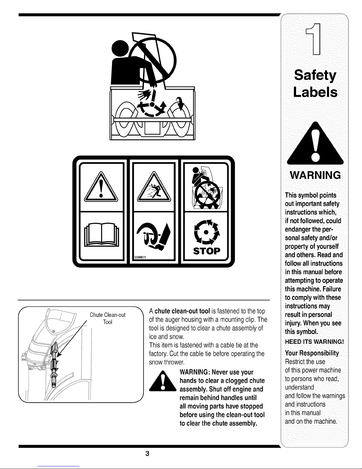
A chute clean-out tool isfastened to the top
of the auger housingwith a mountingclip. The
tool is designedto clear a chuteassembly of
ice and snow.
Thisitemis fastenedwith a cabletie at the
factory.Cut the cable tie beforeoperatingthe
snowthrower.
WARNING: Never useyour
handsto clear a clogged chute
assembly.Shut off engine and
,J
remainbehind handles until
all movingparts havestopped
beforeusing theclean-out tool
to clear the chuteassembly.
WARNING
Thissymbol points
out important safety
instructions which,
ifnotfollowed,could
endangerthe per-
sonalsafety and/or
propertyof yourself
and others.Readand
followall instructions
inthis manual before
attemptingto operate
this machine.Failure
to complywith these
instructionsmay
resultin personal
injury.Whenyou see
this symbol.
HEED ITS WARNING!
Your Responsibility
Restrictthe use
of this power machine
to persons who read,
understand
and follow thewarnings
and instructions
inthis manual
and onthe machine.
3
Page 4
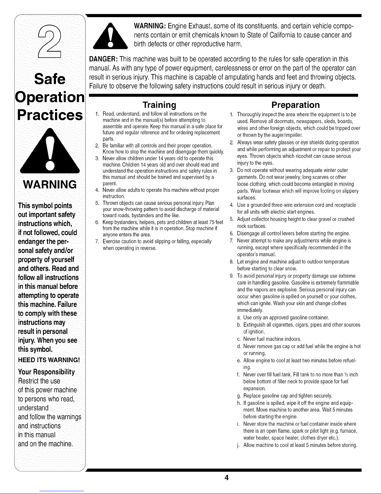
WARNING: Engine Exhaust,some of its constituents,andcertain vehiclecompo-
nentscontain or emit chemicals knownto Stateof Californiato causecancerand
birth defectsor other reproductiveharm.
DANGER: This machinewas builtto be operatedaccordingto the rulesfor safe operation inthis
manual.As with anytype of powerequipment, carelessnessor error onthe part ofthe operator can
result in seriousinjury.This machine iscapable of amputatinghands andfeet andthrowing objects.
Failureto observethe followingsafety instructionscould resultin serious injury or death.
WARNING
i out importantsafety
i instructionswhich,
i if notfollowed,could
i endangerthe per-
sonalsafetyand/or
propertyofyourself
andothers. Readand
followall instructions
inthis manual before
attemptingto operate
i this machine.Failure
! to complywith these
i instructionsmay
i result inpersonal
i injury.When you see
I this symbol.
i HEED ITS WARNING!
;;Your Responsibility
i Restricttheuse
i of this powermachine
to personswho read,
understand
andfollow the warnings
and instructions
inthis manual
andon the machine.
Training
1. Read,understand,andfollowallinstructionsonthe 1.
machineandin themanual(s)beforeattemptingto
assembleandoperate.Keepthis manualinasafe placefor
futureandregularreferenceandfor orderingreplacement
parts. 2.
2. Befamiliarwithall controlsandtheir properoperation.
Knowhowto stopthe machineanddisengagethemquickly.
3. Neverallowchildrenunder14 yearsoldto operatethis
machine.Children14yearsoldandovershouldreadand
understandtheoperationinstructionsand safetyrulesin 3.
thismanualandshouldbetrainedandsupervisedbya
parent.
4. Neverallowadultsto operatethis machinewithoutproper
instruction.
5. Thrownobjectscancauseseriouspersonalinjury.Plan 4.
yoursnow-throwingpatternto avoiddischargeof material
towardroads,bystandersandthe like.
6. Keepbystanders,helpers,petsandchildrenatleast 75feet 5.
fromthe machinewhileit isin operation.Stopmachineif
anyoneentersthearea. 6.
7. Exercisecautiontoavoidslippingor falling,especially 7.
whenoperatinginreverse.
Preparation
Thoroughlyinspectthe areawherethe equipmentisto be
used.Removealldoormats,newspapers,sleds,boards,
wiresand otherforeignobjects,whichcouldbetripped over
orthrownbythe auger/impeller.
Alwayswearsafetyglassesor eyeshieldsduringoperation
andwhile performinganadjustmentorrepairto protectyour
eyes.Thrownobjectswhich ricochetcancauseserious
injurytothe eyes.
Do notoperatewithoutwearingadequatewinterouter
garments.Donotwearjewelry,longscarvesorother
looseclothing,whichcould becomeentangledin moving
parts.Wearfootwearwhich willimprovefootingonslippery
surfaces.
Useagroundedthree-wireextensioncordand receptacle
forall unitswithelectricstartengines.
Adjustcollectorhousingheighttocleargravel orcrushed
rocksurfaces.
Disengageallcontrolleversbeforestartingthe engine.
Neverattemptto makeanyadjustmentswhileengineis
running,exceptwherespecificallyrecommendedinthe
operator'smanual.
8,
Letengineandmachineadjustto outdoortemperature
beforestartingto clearsnow.
9.
Toavoidpersonalinjuryor propertydamageuseextreme
careinhandlinggasoline.Gasolineisextremelyflammable
andthe vaporsareexplosive.Seriouspersonalinjurycan
occurwhengasolineis spilledonyourselforyour clothes,
whichcanignite.Washyourskinand changeclothes
immediately.
a. Useonlyan approvedgasolinecontainer.
b. Extinguishallcigarettes,cigars, pipesandothersources
ofignition.
c. Neverfuel machineindoors.
d. Neverremovegascap oradd fuelwhilethe engineis hot
or running.
e. Allowengineto coolat leasttwo minutesbeforerefuel-
ing.
f. Neveroverfill fueltank. Filltankto nomorethanY2inch
belowbottomoffiller neckto providespacefor fuel
expansion.
g. Replacegasolinecap andtightensecurely.
h. Ifgasolineis spilled,wipe itoff theengineand equip-
ment.Movemachinetoanotherarea.Wait5 minutes
beforestartingtheengine.
i. Neverstorethe machineorfuel containerinsidewhere
there isan openflame,sparkor pilotlight (e.g.furnace,
waterheater,spaceheater,clothesdryeretc.).
j. Allowmachinetocoolat least5 minutesbeforestoring.
4
Page 5
Operation
1. Donot puthandsorfeetnearrotatingparts,inthe
auger/impellerhousingor chuteassembly.Contactwiththe
rotatingpartscanamputatehandsandfeet.
2. The auger/impellercontrolleveris asafetydevice.Never
bypassitsoperation.Doingsomakesthe machineunsafe
andmaycausepersonalinjury.
3. The controlleversmustoperateeasilyin bothdirections
andautomaticallyreturntothe disengagedpositionwhen
released.
4. Neveroperatewitha missingor damagedchuteassembly.
Keepall safetydevicesin placeandworking.
5. Neverrunan engineindoorsor in a poorlyventilatedarea.
Engineexhaustcontainscarbonmonoxide,anodorlessand
deadlygas.
6. Donotoperatemachinewhile underthe influenceof alcohol
or drugs.
7. Mufflerandenginebecomehotandcan causeaburn.Do
nottouch.
8. Exerciseextremecautionwhenoperatingonor crossing
gravelsurfaces.Stayalert for hiddenhazardsortraffic.
9. Exercisecautionwhenchangingdirectionandwhileoperat-
ingon slopes.
10.Planyoursnow-throwingpatternto avoiddischargetowards
windows,walls,carsetc.Thus,avoidingpossibleproperty
damageor personalinjury causedbyaricochet.
11.Neverdirectdischargeatchildren,bystandersand petsor
allow anyonein frontofthe machine.
12.Donotoverloadmachinecapacitybyattemptingto clear
snowat toofast ofa rate.
13.Neveroperatethis machinewithoutgoodvisibility or light.
Alwaysbe sure of yourfootingand keepa firmholdonthe
handles.Walk,neverrun.
14.Disengagepowerto the auger/impellerwhentransportingor
notin use.
15.Neveroperatemachineat hightransportspeedsonslippery
surfaces.Lookdownandbehindand usecarewhen
backingup.
16.Ifthe machineshouldstartto vibrateabnormally,stopthe
engine,disconnectthesparkplugwireand groundit against
the engine.Inspectthoroughlyfordamage.Repairany
damagebeforestartingandoperating.
17.Disengageallcontrolleversandstopenginebeforeyou
leavethe operatingposition(behindthehandles).Wait
untilthe auger/impellercomesto a completestop before
uncloggingthe chuteassembly,makinganyadjustments,or
inspections.
18.Neverputyourhandin thedischargeor collectoropenings.
Alwaysuse the clean-outtoolprovidedto unclogthe dis-
chargeopening.Donot unclogchuteassemblywhileengine
isrunning.Shut offengineand remainbehindhandlesuntil
all movingpartshavestoppedbeforeunclogging.
19.Useonlyattachmentsandaccessoriesapprovedbythe
manufacturer(e.g.wheelweights,tire chains,cabsetc.).
20. If situationsoccurwhich arenotcoveredin this manual,use
careand goodjudgment.Call customerassistanceforthe
nameof yournearestservicingdealer.
Maintenance & Storage
1. Nevertamperwithsafetydevices.Checktheirproper
operationregularly.
2. Disengageall controlleversandstoptheengine.Waituntil
theauger/impellercometo a completestop.Disconnectthe
sparkplugwireand groundagainsttheengineto prevent
unintendedstartingbeforecleaning,repairing,orinspecting.
3. Checkbolts and screwsforpropertightnessat frequent
intervalstokeepthe machinein safeworkingcondition.
Also,visuallyinspectmachineforanydamage.
4. Do notchangethe enginegovernorsettingor over-speed
theengine.Thegovernorcontrolsthemaximumsafe
operatingspeedoftheengine.
5. Snowthrowershaveplatesand skidshoesare subjectto
wearanddamage.Foryoursafetyprotection,frequently
checkallcomponentsandreplacewith originalequipment
manufacturer's(OEM) partsonly."Useof partswhichdo
notmeetthe originalequipmentspecificationsmayleadto
improperperformanceandcompromisesafety!"
6. Checkcontrolsperiodicallytoverify theyengageand
disengageproperlyandadjust,if necessary.Referto the
adjustmentsectioninthis operator'smanualfor instructions.
7. Maintainor replacesafetyandinstructionlabels,as neces-
sary.
8. Observeproperdisposallawsandregulationsfor gas,oil,
etc.to protectthe environment.
9. Priorto storing,run machinea few minutesto clearsnow
frommachineand preventfreezeupof auger/impeller.
10.Neverstorethe machineorfuel containerinsidewhere
thereisan openflame,sparkor pilot lightsuchas a water
heater,furnace,clothesdryeretc.
11.Alwaysreferto theoperator'smanualfor properinstructions
onoff-seasonstorage.
Do not modify engine
Toavoidseriousinjuryordeath,donot modifyengineinany
way.Tamperingwiththegovernorsettingcan leadto a runaway
engineandcauseit tooperateatunsafespeeds.Nevertamper
withfactorysettingof enginegovernor.
Notice regarding Emissions
Engineswhicharecertifiedto complywithCaliforniaandfederal
EPAemissionregulationsforSORE(SmallOff RoadEquipment)
arecertifiedtooperateonregularunleadedgasoline,andmay
includethefollowingemissioncontrolsystems:EngineModifica-
tion(EM)andThreeWayCatalyst(TWC)ifso equipped.
ces
WARNING
endangerthe per-
sonalsafety and/or
property of yourself
and others. Readand
followall instructions
in this manual before
attemptingto operate
this machine. Failure
to complywith these
instructionsmay
result in personal
injury.When you see
Ihis symbol.
HEED IT'S WARNING!
_our Responsibility
Restrictthe use
ofthis powermachine
to personswho read,
understand
andfollow the warnings
and instructions
in this manua
and onthe machine.
5
Page 6
NOTE:Referencesto
rightorleftsideofthe
snowthroweraredeter-
minedfrombehindthe
unitintheoperating
position.
Figure 1
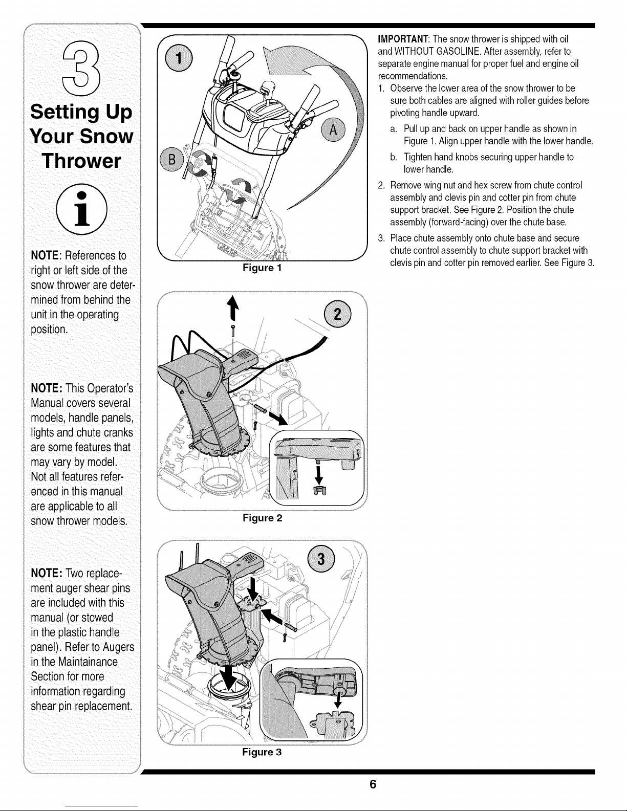
IMPORTANT:Thesnowthrowerisshippedwithoil
andWITHOUTGASOLINE.Afterassembly,referto
separateenginemanualfor properfuelandengineoil
recommendations.
1. Observethelowerareaof the snowthrowertobe
surebothcablesarealignedwithrollerguidesbefore
pivotinghandleupward,
a. Pullupand backon upperhandleas shownin
Figure1.Alignupperhandlewiththe lowerhandle,
b. Tightenhandknobssecuringupperhandleto
lowerhandle,
2. Removewingnutand hexscrewfromchutecontrol
assemblyandclevispinandcotterpinfromchute
supportbracket.SeeFigure2. Positionthechute
assembly(forward-facing)overthechutebase.
3. Placechuteassemblyontochutebaseand secure
chutecontrolassemblytochutesupportbracketwith
clevispinandcotterpin removedearlier.SeeFigure3.
NOTE:ThisOperator's
Manualcoversseveral
models,handlepanels,
i lightsandchutecranks
aresomefeaturesthat
mayvarybymodel.
Notallfeaturesrefer-
encedinthismanual
areapplicabletoall
snowthrowermodels.
I NOTE:Tworeplace-
mentaugershearpins
i areincludedwiththis
manual(orstowed
intheplastichandle
i panel).RefertoAugers
intheMaintainance
i Sectionformore
i informationregarding
shearpinreplacement.
Figure 2
Figure 3
6
Page 7
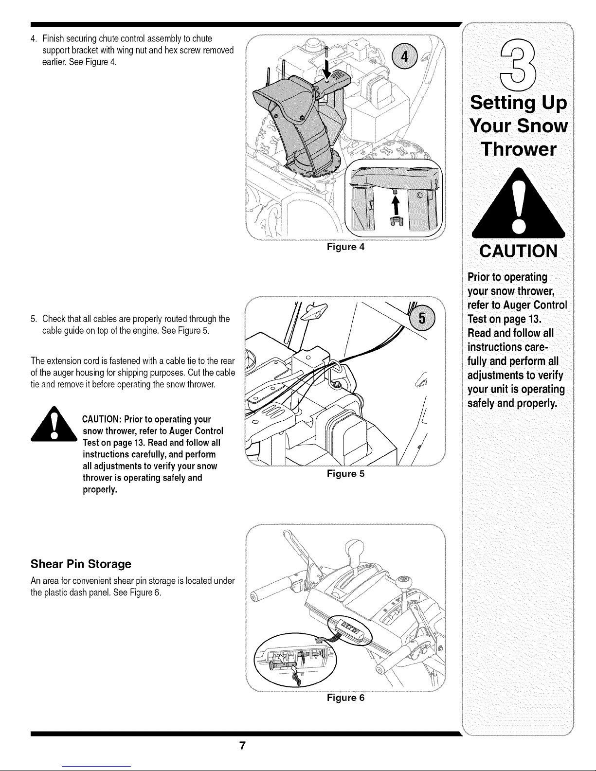
4, Finishsecuringchutecontrolassemblytochute
supportbracketwithwingnut andhexscrewremoved
earlier,SeeFigure4,
5, Checkthatall cablesareproperlyroutedthroughthe
cableguideon topoftheengine,SeeFigure5,
Theextensioncord isfastenedwitha cabletieto the rear
oftheaugerhousingforshippingpurposes,Cutthecable
tieand removeit beforeoperatingthesnowthrower,
CAUTION:Priortooperatingyour
snowthrower,refertoAugerControl
Teston page13.Readandfollow all
instructionscarefully,andperform
alladjustmentsto verifyyoursnow
throwerisoperatingsafelyand
properly.
Figure 4
Priorto operating
your snowthrower,
referto Auger Control
Teston page 13.
Read and follow all
instructionscare-
fully and perform all
adjustmentstoverify
your unit isoperating
safelyand properly.
Figure 5
Shear Pin Storage
An areafor convenientshearpin storageis locatedunder
theplasticdashpanel,SeeFigure6,
Figure 6
7
Page 8
i
WARNING
Neveruse your hands
to clean snow and
icefrom the chute
assemblyor auger
housing.
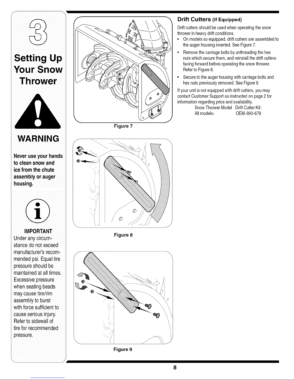
Drift Cutters (If Equipped)
Driftcuttersshouldbeusedwhenoperatingthesnow
throwerinheavydriftconditions,
• Onmodelsso equipped,driftcuttersare assembledto
theaugerhousinginverted,SeeFigure7,
• Removethecarriageboltsbyunthreadingthehex
nutswhichsecurethem,and reinstallthedriftcutters
facingforwardbeforeoperatingthesnowthrower.
Referto Figure8,
• Securetothe augerhousingwithcarriageboltsand
hexnutspreviouslyremoved,SeeFigure9,
If yourunitis notequippedwithdriftcutters,youmay
contactCustomerSupportas instructedonpage2for
informationregardingpriceand availability,
SnowThrowerModel DriftCutterKit:
Allmodels- OEM-390-679
Figure 7
IMPORTANT
Underany circum-
stance do not exceed
manufacturer'srecom-
mended psi. Equaltire
pressureshouldbe
maintainedat all times.
Excessivepressure
i when seatingbeads
maycausetire/rim
assemblyto burst
with forcesufficientto
cause seriousinjury.
i Referto sidewallof
i tire for recommended
i pressure.
Figure 8
Figure 9
8
Page 9
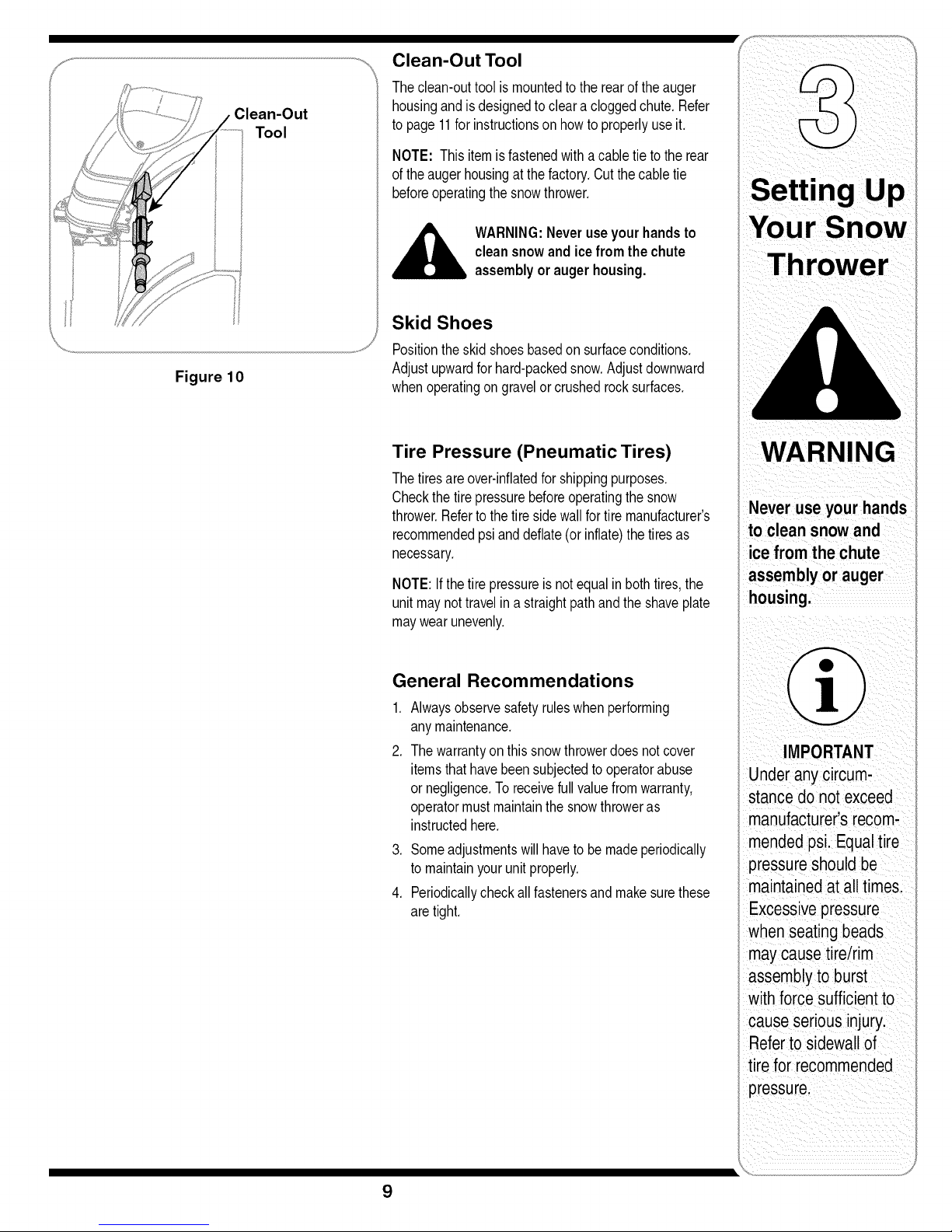
Figure 10
Clean-Out
Tool
Clean-Out Tool
Theclean-outtool is mountedtothe rearoftheauger
housingandis designedtocleara cloggedchute.Refer
topage11forinstructionson howtoproperlyuseit.
NOTE: This itemisfastenedwith acabletie tothe rear
oftheaugerhousingatthe factory.Cutthecabletie
beforeoperatingthesnowthrower.
,_ WARNING:Neveruseyourhandsto
cleansnowandice fromthe chute
assemblyor augerhousing.
Skid Shoes
Positiontheskid shoesbasedon surfaceconditions.
Adjustupwardforhard-packedsnow.Adjustdownward
whenoperatingongravelorcrushedrocksurfaces.
g
Your Snow
Tire Pressure (Pneumatic Tires)
Thetiresareover-inflatedforshippingpurposes.
Checkthetirepressurebeforeoperatingthesnow
thrower.Refertothetiresidewallfortiremanufacturer's
recommendedpsianddeflate(or inflate)thetiresas
necessary.
NOTE:If thetirepressureis notequalin bothtires,the
unitmaynottravelin astraightpathandthe shaveplate
maywearunevenly.
General Recommendations
,
Alwaysobservesafetyruleswhenperforming
anymaintenance.
2,
Thewarrantyon thissnowthrowerdoesnotcover
itemsthathavebeensubjectedtooperatorabuse
or negligence.To receivefullvaluefromwarranty,
operatormustmaintainthe snowthroweras
instructedhere.
3. Someadjustmentswillhaveto bemadeperiodically
tomaintainyourunitproperly.
4. Periodicallycheckall fastenersandmakesurethese
aretight.
WA RNING
Under anycircum,
stance do not exceed
manufactureCs recom:
mendedpsi.Equal tire
pressureshould be
maintained at all times,
when seatingbeads
maycausetire/rim
assemblytoburst
with forcesufficienttO
cause seriousinjury.
Referto sidewallOf
tire forrecommended
i I ii_ii ii i _ i i
9
Page 10

Know Your Snow Thrower
f
HeatedHandles
Switch(en option)l-
Drive Control
.ShiftLever
Four-Way
ChuteControFM
JgerControl
WARNING
Read, understand,
andfollow all instruc-
Lionsand warnings
onthe machineand
in thismanual before
operating.
Useextreme care
when handling
gasoline.Gasoline is
extremelyflammable
andthe vapors are
explosive.Neverfuel
the machine indoors
or while the engine
is hotor running.
Extinguishcigarettes,
cigars,pipes and
other sources of
ignition.
Headlig
ElectricStart
GasCa
Oil
1 If Equipped
Figure 11
Nowthatyouhavesetup yoursnowthrowerfor opera-
tion,getacquaintedwithits controlsandfeatures.These
aredescribedbelowandillustratedin Figure11.This
knowledgewillallow youto use yournewequipmentto
itsfullestpotential.
NOTE: Fordetailedstartinginstructionsandmore
informationonall enginecontrols,refertotheseparate
enginemanualpackedwithyour unit.
Shift Lever
6
Theshiftleverislocatedon therightside
ofthehandlepanel.Placetheshiftlever
intoany of eightpositionstocontrolthe
directionof travelandgroundspeed.
Forward
Yoursnowthrowerhassixforward(F)
speeds,withpositionnumberone (1)
beingtheslowestspeed.
Reverse
Yoursnowthrowerhastwo reverse(R)
speeds,withpositionnumberone (1)
beingtheslowerspeed.
5
4
3
t 2
F1
R1
R2
WheelSteering
Control
EngineControls
RecoilStarter
ElectricStarter Outlet
Primer
Ignition
Key
Choke
Control
Clean-Out
Handle
tool
Throttle
Control
Choke Control
I111
Thechokecontrolisfoundontherearof theengineand
isactivatedbyrotatingtheknobclockwise.Activatingthe
chokecontrolclosesthe chokeplateon thecarburetor
andaidsinstartingthe engine.
Throttle Control
Thethrottlecontrolis locatedonthe engine.
It regulatesthespeedoftheengineand
willshutoff theenginewhenpusheddown
completely.
Primer
Depressingthe primerforcesfuel directly
intothe engine'scarburetortoaidin cold-
weatherstarting.
Oil Fill
Engineoil levelcanbecheckedandoil
addedthroughtheoil fill.
q;::b,
J
@
10
Page 11

Auger Control
f
AUGER
CONTROL
• Tochangethe directioninwhichsnowisthrown,
squeezethe buttononthejoy-stickandpivotthe
joy-stickto the rightorto the left.
• Tochangethe angle/distancewhichsnowisthrown,
pivotthejoy-stickforwardor backward.
Wheel Steering Controls
Theleftand rightwheelsteeringcontrolsarelocatedon
theundersideofthehandles.Squeezetherightcontrolto
turnright;squeezetheleftcontroltoturnleft.
NOTE:Operatethesnowthrowerin openareasuntilyou
J
arefamiliarwiththesecontrols.
Theaugercontrolislocatedonthe left handle.Squeeze
thecontrolgripagainstthehandleto engagethe augers
andstartsnowthrowingaction.Releasetostop.
Drive Control/Auger Control Lock
f DRIVE _
CONTROL
Thedrivecontrolis locatedontherighthandle.Squeeze
thecontrolgripagainstthehandleto engagethe wheel
drive.Releasetostop.
Thedrivecontrolalsolockstheaugercontrolsoyoucan
operatethechutedirectionalcontrolwithoutinterrupting
thesnowthrowingprocess.If theaugercontrolisen-
gagedsimultaneouslywiththe drivecontrol,theoperator
canreleasetheaugercontrol(onthe lefthandle)and
theaugerswillremainengaged.Releasebothcontrolsto
stoptheaugersandwheeldrive.
IMPORTANT:Alwaysreleasethedrivecontrolbefore
changingspeeds.
Four-Way Chute Control TM
f
CHUTE DIRECTIONAL CONTROL
CHUTETILTDOWN
0
JPUSHBUTTONJ
CHUTEROTATE_.
LEFT "q
JPUSH BUTTONJ
CHUTEROTATE
RIGHT
9
_. CHUTETILTUP j
Thechutedirectionalcontrolislocatedon theleftsideof
thedash panel.
Ignition Key
Theignitionkeymustbe insertedandsnappedinplace
inorderfortheengineto start. Removetheignitionkeyto
preventunauthorizeduseof equipment.DoNOTattempt
toturnthekey.
Clean-Out Tool
WARNING:Neveruseyour handsto
clearacloggedchuteassembly.Shut
offengineandremainbehindhandles
untilall movingpartshavestopped
beforeunclogging.
,
Releaseboththe augercontroland thedrive/auger
controllock.
2. Stoptheenginebymovingthethrottletothestop
position.
3. Removetheclean-outtoolfromthe mountingclip.
4. Usethe shovel-shapedendof the clean-outtoolto
removeanysnowandice inthechuteassembly.
5. Re-fastenthe clean-outtoolto themountingclipon
therearofthe augerhousingand restartengine.
6. Whilestandingin theoperator'sposition(behindthe
snowthrower),engagethe augercontrolfora few
secondsto clearany remainingsnowor icefromthe
chuteassemblybeforecontinuingtoclearsnow.
Heated Handles Switch (If Equipped)
Thisswitchis locatedonthe rightsideofthe snow
throwerdashpanel.Toactivatetheheatedhandles,
togglethe switchto the rightto generateheatwithinthe
handlegrips.Toggletheswitchto thelefttotheOFF
positionafterusingthesnowthrower.
NOTE:Theheatedhandlesgripsarea complimentto,
nota substitutefor,propercoldweatherouterwearfor
theoperator'shands.Itis recommendedthatthe snow
throweroperatorweargloves/mittensto avoidextremities
ofwinterwhileoperatingthisequipment.
WARNING
The operation of
any snowthrower
can result inforeign
objects beingthrown
intothe eyes, which
candamage your
eyesseverely.Always
wear safetyglasses
while operating the
snowthrower,or while
performing anyadjust-
ments or repairson it.
throwerwhile starting
engineor operating
snowthrower. Never
run engine indoors or
in enclosed,poorly
ventilatedareas. En-
gine exhaustcontains
carbon monoxide,an
odorless and deadly
gas. Keep hands,feet,
hairand looseclothing
awayfrom any moving
parts onengine and
snowthrower.
11
Page 12

Servicetheenginewithgasolineandoil asinstructedin
theseparateenginemanualpackedwithyour unit,Read
instructionscarefully.
!iii i iii i ii!i/ iiii
WARNING
Starting The Engine
1, Attachsparkplugwireto sparkplug.Makecertainthe
metalloopon theendofthesparkplugwire(inside
therubberboot)is fastenedsecurelyoverthe metal
tiponthesparkplug.
2, Makecertainboththeaugercontrolanddrivecontrol
arein thedisengaged(released)position,
3, Movethrottlecontrolupto FASTposition.Insert
ignitionkeyinto slot. Makesureitsnapsintoplace.
Donotattemptto turnthe key,
Gas & Oil Fill-Up
7, Whendisconnectingtheextensioncord,always
unplugtheendat thethree-prongwalloutletbefore
unpluggingtheoppositeendfromthesnowthrower.
Recoil Starter
1, Rotatechokecontrolto FULLchokeposition(cold
enginestart),
NOTE:If the engineisalreadywarm,placechokecontrol
intheOFFpositioninsteadof FULL.
2, Pushthe primertwoor threetimesforcoldengine
start,makingsuretocoverventholeinthecenterof
theprimerwhenpushing,
NOTE:DO NOTuse primerto restartawarmengine
aftera shortshutdown.
Read, understand,
and followall instruc-
tions andwarnings
onthe machineand
in thismanual before
operating.
Useextreme care
when handling
gasoline.Gasoline is
extremelyflammable
and thevapors are
explosive.Neverfuel
the machine indoors
or while the engine
is hot or running.
Extinguishciga-
rettes, cigars, pipes
and othersources of
ignition.
Ifyour home'swiring
system is not a
three-wire grounded
system,do not use
this electricstarter
under anycondi-
tions.
Ifyour home
electricalsystem
is grounded,
but a three-hole
receptacle is not
available,do not use
your snow thrower's
electricstarter.
NOTE:The enginecannotstart unlessthe keyis
insertedintoignitionswitch,
Electric Starter
1, Determinethatyourhome'swiringis a three-wire
groundedsystem,Ask alicensedelectricianifyou are
notcertain.
WARNING:Theoptionalelectricstarter
,__is equippedwitha groundedthree-wire
If youhavea groundedthree-prongreceptacle,proceed
asfollows:
1, Plugtheextensioncordintotheoutletlocatedon the
engine'ssurface,Plugtheotherendof extensioncord
intoa three-prong120-volt,grounded,ACoutletina
well-ventilatedarea.
2, RotatechokecontroltoFULLchokeposition(fora
coldenginestart),
NOTE:Ifthe engineis alreadywarm,placechokecontrol
inthe OFFpositioninsteadofFULL.
3, Pushtheprimertwoor threetimesforcoldengine
start,makingsuretocoverventholein thecenterof
theprimerwhenpushing,
NOTE:DONOTuseprimerto restartawarmengine
aftera shortshutdown.
4, Pushstarterbuttonto start engine.
5, Oncetheenginestarts,immediatelyreleasestarter
button.
6, Astheenginewarms,slowlyrotatethechokecontrol
totheOFFposition.Iftheenginefalters,quickly
rotatethechokecontrolbackto FULLandthenslowly
intothe OFFpositionagain.
powercordandplug,andis designed
tooperateon120voltAC household
current.It mustbe usedwitha properly
groundedthree-prongreceptacleatall
timesto avoidthe possibilityofelectric
shock.Followall instructionscarefully
priorto operatingtheelectricstarter.
NOTE:Additionalprimingmaybe necessaryifthe
temperatureis below15oFahrenheit,
3, Graspthe recoilstarterhandleandslowlypullthe
ropeout,Atthepointwhereit becomesslightlyharder
topulltherope,slowlyallowthe ropeto recoil.
4, Pullthe starterhandlewitha firm,rapidstroke,Donot
releasethehandleandallowitto snapback,Keepa
firmholdon thestarterhandleandallowit to slowly
recoil,
,
Asthe enginewarms,slowlyrotatethechokecontrol
totheOFFposition.Iftheenginefalters,quicklyrotate
thechokecontrolbacktothe FULLpositionandthen
slowlyintotheOFFpositionagain.
NOTE:Allowtheenginetowarmup fora few minutes
afterstarting.Theenginewill notdevelopfull poweruntil
itreachesoperatingtemperatures.
Stopping The Engine
Runenginefor a fewminutesbeforestoppingtohelpdry
offanymoistureontheengine.
• Tohelppreventpossiblestarterfreeze-up,proceedas
follows:
Electric Starter (If Equipped)
1, Connectextensioncordto the electricstarteroutlet
ontheengine,thento 120voltACoutlet.
2, Withtheenginerunning,pushthestarterbuttonand
allowthe starterforspinforseveralseconds,The
noisemadebythestarteris normal,Theengine's
starteris not beingharmed.
3, Whendisconnectingtheextensioncord,always
unplugtheendat thethree-prongwalloutletbefore
unpluggingtheoppositeendfromthesnowthrower.
4, MovethrottlecontroltoSTOPposition.
5, Removetheignitionkey(Donotturn key)to prevent
unauthorizeduseof equipment,
6, Wipeallsnowandmoisturefromtheareaaroundthe
engineaswell as theareainandaroundthe drive
controlandaugercontrol,Also,engageandrelease
bothcontrolsseveraltimes.
12
Page 13

NOTE:Keepthekeyin asafeplace.Theenginecannot
startwithouttheignitionkey.
Recoil Starter
1. Withenginerunning,pullstarterropewitha rapid,
continuousfull arm strokethreeor fourtimes.Pulling
thestarterropewill producea loudclatteringsound,
whichisnotharmfultoengine.
2. MovethrottlecontroltoSTOPposition.
3. Removethe ignitionkey(Do notturnkey)toprevent
unauthorizeduseof equipment.
NOTE:Keepthekeyin asafeplace.Theenginecannot
startwithouttheignitionkey.
4. Wipeall snowandmoisturefromtheareaaroundthe
engineaswellas theareain andaroundthedrive
controlandaugercontrol.Also,engageand release
bothcontrolsseveraltimes.
To Engage Drive
Withtheenginerunningneartopspeed,move
shiftleverto oneof sixFORWARDpositionsor two
REVERSEpositions.Selecta speedappropriatefor
thesnowconditionsthatexist.
2. Squeezedrivecontrolagainstthe righthandleand
thesnowthrowerwillmove.Releaseitandthedrive
motionwillstop.
3. Toturnthe unitleftor right,squeezetherespective
wheelsteeringcontrol.SeeFigure11.
2. Ina well-ventilatedarea,startthesnowthrower
engineasinstructedonthepreviouspage.Makesure
thethrottleis setin the FASTposition.
3. Whilestandingin theoperator'sposition(behindthe
snowthrower),engagethe auger.
4. Allowtheaugerto remainengagedforapproximately
ten(10)secondsbeforereleasingtheaugercontrol.
Repeatthisseveraltimes.
5. Withthe throttlecontrolin theFAST(rabbit)position
andtheaugercontrolinthedisengaged"up"position,
walktothefrontofthemachine.
6. Confirmthattheaugerhascompletelystopped
rotatingandshowsNOsignsofmotion.Iftheauger
showsANYsignsofrotating,immediatelyreturnto
theoperator'spositionandshutofftheengine.Wait
forALLmovingpartsto stopbeforere-adjustingthe
augercontrol.
7. Toreadjustthecontrolcable,loosentheupperhex
nutontheaugercablebracket.
8. Positionthebracketupwardtoprovidemoreslack(or
downwardtoincreasecabletension).See Figure12.
9. Retightentheupperhexnut.
10.RepeatAugerControlTesttoverifyproperadjustment
hasbeenachieved.
WARN
Never useyour hands
to clean snow and
ice fromthe chute
The mufflerlengine
and surrounding
areas become hot
burn. Do nottouch.
To Engage Augers
1. Toengageaugersandstartsnowthrowing,squeeze
thelefthandaugercontrolagainstthe lefthandle.
Releaseto stopaugers.
2. Whiletheaugercontrolisengaged,squeezethedrive
controltomove,releasetostop.Donotshiftspeeds
whilethe driveisengaged.
NOTE:Thissameleveralsolocksaugercontrolso you
canturn the chutecontrolwithoutinterruptingthesnow
throwingprocess.
3. Releasetheaugercontrol;the interlockmechanism
shouldkeeptheaugercontrolengageduntilthe drive
controlis released.
,
Releasethedrivecontrolto stopboththe augersand
thewheeldrive.Tostoptheauger,bothleversmust
be released.
Auger Control Test
Performthefollowingtestbeforeoperatingyoursnow
throwerforthefirsttimeandatthestartofeachwinter.
Checktheadjustmentofthe augercontrolasfollows:
1. Whentheaugercontrolis releasedandin the
disengaged"up"position,thecableshouldhavevery
littleslack.It shouldNOTbetight.
Figure 12
When selectinga
Drive Speed. use the
slowerspeeds until
you are comfortable
and familiar with the
operation of the snow
NEVERrepositionthe
shift lever(change
speeds or direction
control andbringing
the snowthrower
to a complete stop,
Doing so will result in
prematurewear to the
snowthrower's drive
i
i
13
Page 14

///
Shift Cable
If the fullrangeof speeds(forwardandreverse)cannot
beachieved,refertothefiguretotheleftandadjustthe
shiftcable as follows:
1, Placethe shiftleverin thefastest forwardspeed
position,
2, Loosenthehex nuton theshiftcable indexbracket,
SeeFigure13.
3. Pivotthebracketdownwardtotakeupslack inthe
cable,
4, Retightenthehex nut,
5. Checkforcorrectadjustmentbeforeoperatingthe
snowthrower.
WARNING
Read,understand,
and followall instruc-
tions andwarnings
i on the machineand
inthis manual before
, operating.
Neverattempt to
makeanyadjust-
i mentswhile the
_engine is running,
i exceptwhere speci-
i fied in operator's
_manual.
Figure 13
Figure 14
Figure 15
Chute Control
Oncea seasonorevery25hoursofoperation,whichever
isearlier,checkwhetherthefour-waychutecontrolTM
cableshaveslackened,Ifthe chutedoesnot rotate
fullyor itspitchcannotbe movedup ordown,thechute
controlcableswillhaveto beadjusted,
Toadjustthesecables,proceedasfollows:
1. Totightencable,loosenthetop nutand tightenthe
bottomnuton thecable.
2. Adjustequallyonbothsidesby workingonboth
cables,SeeFigure14,
Drive Control & Shift Lever
Whenthedrivecontrolisreleasedandin thedisengaged
"up"position,thecableshouldhaveverylittleslack.It
shouldNOTbetight.
Checktheadjustmentofthe drivecontrolasfollows:
1, Withthedrivecontrolreleased,pushthesnowthrower
gentlyforward,Theunitshouldrollfreely.
2, Engagethedrivecontrolandgentlyattempttopush
thesnowthrowerforward.Thewheelsshouldnot turn.
Theunit shouldnotrollfreely.
3, Withthe drivecontrolreleased,movetheshiftlever
backandforthbetweentheR2positionandthe F6
positionseveraltimes,Thereshouldbeno resistance
in theshiftlever,
4, If anyofthe abovetestsfailed,thedrivecableisin
needofadjustment,Proceedasfollows:
5, Loosenthelowerhexnutonthe drivecablebracket,
if
SeeFigure15,
6, Positionthebracketupwardtoprovidemoreslack(or
downwardto increasecabletension),
7. Retightenthelowerhex nut,
Youcanalsochecktheadjustmentasfollows:
1, Withthesnowthrowertippedforward(becertainto
draingasolineorplaceplasticfilmunderthegascapif
thesnowthrowerhasalreadybeenoperated),remove
theframecoverunderneaththe snowthrowerby
removingtheself-tappingscrews,Referto Figure20
onpage 17.
14
Page 15

2. Withthe drivecontrolreleased,there mustbe 1/8"
clearancebetweenthefrictionwheelandthedrive
pulleyin all positionsof theshiftlever.
3. Withthe drivecontrolengaged,thefrictionwheelmust
contactthedrivepulley.Referto Figure28on page
18.
4. Ifadjustmentisnecessary,loosenthelowerhexnut
on thedrivecableindexbracketandpivotthebracket
upwardordownwardasnecessary.Referto Figure15.
Tightenthelowerhexnutto securethe bracketwhen
correctadjustmentisreached.
5. Reassembletheframecoverandturnthe unitbackto
its operatingposition.
NOTE:Ifyouplacedplasticunderthe gas cap,becertain
to removeit now.
Skid Shoes
Thespacebetweenthisshaveplateandthegroundcan
be adjusted.Forclosesnowremoval,placeskidshoesin
thelowposition.Usemiddleorhighpositionwhenareato
be clearedis uneven.
1.Adjustskidshoesby looseningthefourlocknuts
andcarriageboltsand movingskidshoestodesired
position.SeeFigure16Aor 16B.
2. Makecertainthe entirebottomsurfaceofskidshoes
areagainstthegroundtoavoidunevenwearon the
skidshoes.
3. Tightennutsandboltssecurely.
NOTE: Somemodelsareequippedwith reversibleskid
shoesandmaybeturnedoverto increasetheirlifespan.
See Figure16B.
Auger Control
Toadjusttheaugercontrol,referto page13.
Figure 16A- Standard Skid Shoe
//"
/
Figure 16B - Reversible Skid Shoe
IMPORTANT
It is not recommended
that you operatethis
snowthrower on gravel
as loose gravelcan be
easilypicked up and
thrownby the auger
causingpersonalinjury
ordamageto the snow
thrower.
Iffor some reason,
you haveto operate
thesnowthrower on
_ravel keepthe skid
shoe inthe highest
)ositionfor maximum
clearancebetweenthe
groundand the shave
)late.
15
Page 16

:WARNING
i
,_ WARNING:Alwayswearsafety
Engine
Refertotheseparateenginemanualpackedwithyour
unitfor all enginemaintenance.
glassesduringoperationorwhile
performinganyadjustmentsor
repairs.
Lubrication
Gear (Hex) Shaft
Oncea season,lubricatethe hexshaftwitha penetrat-
ingoil,butnotgrease. RefertoFigure17.
Wheels
Atleastoncea season,removebothwheels.Cleanand
coattheaxleswitha multipurposeautomotivegrease
beforereinstallingwheels.
Auger Shaft
Atleastoncea season,removetheshearpinson auger
shaft.Spraylubricantinsideshaft,aroundthe spacers.
Alsolubricatethe flangebearingsfoundateitherendof
theshaft.SeeFigure24.
Gear Case
Theaugergearcasehasbeenfilled withgreaseat
thefactory.Ifdisassembledforanyreason,lubricate
withtwoouncesof grease(Part Number737-0168).
Beforereassembling,removeoldsealantandapplynew
sealant.
Figure 17
oradjustment on
Avoid oil spillageon
rubberfrictionwheel
and aluminumdrive
plate:
Do notoverfill thegear
casel Damageto the
sealscould result.
NOTE:Donot overfillthegearcase. Damagetothe
sealscouldresult.Besurethe ventplugisfreeof
greaseinorderto relievepressure.
Drive Mechanism
Removerearcover.Oilanychains,sprockets,gears,
bearings,shafts,andshiftingmechanismat leastonce
a season.Useengineoilor a spraylubricant.Avoid
gettingoil on rubberfrictionwheelandaluminumdrive
plate.
Engine
Refertotheseparateenginemanualpackedwithyour
unitfor all enginelubricationinstructions.
Drive/Auger Control Lock
Thecamon theendsofthecontrolrodswhichinterlock
thedriveandaugercontrolsmustbelubricatedatleast
oncea seasonorevery25hoursofoperationusing
a multi-purposeautomotivegrease.Thecamcan be
accessedbeneathhandlepanel.
Shave Plate and Skid Shoes
Theshaveplateand skidshoesonthebottomofthe
snowthroweraresubjecttowear.Theyshouldbe
checkedperiodicallyandreplacedwhennecessary.
Toremoveskidshoes:
1. Removethefourcarriageboltsandhexflangenuts
whichsecurethemtothesnowthrower.
2. Reassemblenewskidshoeswiththefourcarriage
bolts(twooneachside)andhexflangenuts.Refer
toFigures18Aor 18B.
Figure 18A- Standard Skid Shoe
Figure 18B - Reversible Skid Shoe
Toremoveshaveplate:
1. Removethecarriageboltsand hexnutswhichattach
itandtheskidshoesto thesnowthrowerhousing.
2. Reassemblenewshaveplate,makingsureheadsof
carriageboltsaretotheinsideofhousing.Tighten
securely.
16
Page 17

!
Auger Belt Replacement
Toremoveandreplaceyoursnowthrower'saugerbelt,
proceedasfollows:
1. Removethe plasticbeltcoveronthe frontofthe
enginebyremovingthetwoself-tappingscrews.
Figure 19
NOTE:Drainthegasolinefromthesnowthrower,or
placea pieceof plasticunderthegascap.
2. Carefullypivotthesnowthrowerup andforwardso
,J
thatit restsonthe augerhousing.Removetheframe
coverfromtheundersideofthesnowthrowerby
removingfourself-tappingscrewswhichsecureit.
3. Rolltheaugerbeltoff theenginepulley.
4. a. Loosenandremovetheshoulderscrewwhich
actsas a beltkeeper.
b. Unhookthesupportbracketspringfromthe
frame.
5. Removethe beltfromaroundtheaugerpulley,and
slipthe beltbetweenthesupportbracketandthe
augerpulley.Reassembleaugerbeltbyfollowing
instructionsin reverseorder.
Maintaining
Your Snow
Thrower
NOTE:Although
multi-viscosityoils
(5W30,10W30etc.)
improvestarting incold
weather,thesemulti-
viscosity oils also result
in higheroil consump-
tion when usedabove
32°F(0°C). Checkyour
NOTE:DoNOTforgetto reinstallthe shoulderscrew
Figure 20
f
andreconnectthespringtotheframeafterinstalling
a replacementaugerbeltandto removethepieceof
plasticfromunderthegascap.
snow thrower'sengine
oil level morefrequently
to avoid possible
enginedamagefrom
runninglow onoil.
NOTE: Donot sand-
blastspark plug. Spark
plugshould becleaned
byscraping orw=re
brushingand washing
with a commercial
solvent.
Figure 21
Figure 22
IMPORTANT
NEVER replacethe
_ugershear pinswith
standardpins.Any
damageto theauger
gearboxor other com-
3onents,as a resultof
doing so,will NOTbe
coveredby yoursnow
thrower'swarranty.
Figure 23
17
Page 18

;now
Augers
. Theaugersaresecuredtothespiralshaftwithtwo
shearpinsandcotterpins,If theaugershouldstrike
a foreignobjector icejam,thesnowthroweris
designedsothatthe pinsmayshear,
• If theaugerswillnotturn,checkto seeifthepins
havesheared,Onesetof replacementshearpins
hasbeenprovidedwiththe snowthrower.When
replacingpins,sprayanoil lubricantintoshaft before
insertingnewpins,
Pin Spacers
Figure 24
I
Bearing
WARNING
Alwaysstop engine,
disconnectspark
plug, andground
against engine before
cleaning,lubricating
or doing any kind
of maintenanceor
adjustments onyour
_machine.
Drive Belt Replacement 2,
Toremoveand replaceyoursnowthrower'sauger
belt,proceedasfollows:
1, Removetheplasticbeltcoveronthefrontof the
enginebyremovingthetwoself-tappingscrews.
° Drainthegasolinefromthesnowthrower,orplace
a pieceof plasticunderthegascap,
° Carefullypivotthesnowthrowerupandforwardso
that it restson theaugerhousing. °
Removetheframecoverfromthe undersideofthe
snowthrowerbyremovingfourself-tappingscrews
whichsecureit,
3, a, Grasptheidlerpulleyandpivotit towardtheright.
b, Rollthe augerbeltoff theenginepulley.
c, Liftthedrivebeltoffenginepulley.
4, Slipthe drivebeltoff the pulleyandbetweenfriction
wheelandfrictionwheeldisc.
Removeandreplacebeltinthe reverseorder.
Figure 25
/
Figure 26
\ J
Figure 27
in
fi s
Figure 28
18
Page 19

Figure 29
Figure 30
Friction Wheel Removal
If the snowthrowerfailstodrivewiththedrivecontrol
engaged,and performingthedrivecontrolcableadjust-
menton page12failsto correcttheproblem,thefriction
wheelmayneedtobe replaced.Followtheinstructions
below.Examinethefrictionwheelfor signsof wearor
crackingandreplaceifnecessary.
• Placetheshiftleverin thirdForward(F3)position.
• Drainthegasolinefromthesnowthrower,or placea
pieceof plasticunderthegas cap.
• Carefullypivotthesnowthrowerup andforwardso
thatit restsonthe augerhousing.
1. a. Removetheframecoverfromthe undersideofthe
snowthrowerbyremovingfourself-tappingscrews
whichsecureit.
b. Removethe right-handwheelbyremovingthe
screwandcuppedwasherwhichsecureit to the
axle.
2. Carefullyremovethehex nutandwasherwhich
securesthehexshafttothesnowthrowerframeand
lightlytaptheshaft'sendtodislodgethe ballbearing
fromthe rightsideofthe frame.
3. Carefullypositionthehexshaftdownwardandto the
leftbeforecarefullyslidingthefrictionwheelassembly
offtheshaft.
NOTE:Ifyou'rereplacingthefrictionwheelassembly
asa whole,discardthewornpartand slidethenewpart
ontothe hex shaft.Followthestepsabovein reverse
orderto reassemblecomponents.Ifyou'redisassembling
thefrictionwheeland replacingonlytherubberring,
proceedasfollows:
4. Removethefour screwswhichsecurethefriction
wheel'ssideplatestogether.
• Removethe rubberringfrombetweentheplates.
J
• Reassembletheside plateswitha newrubberring.
• Slidethefrictionwheelassemblybackontothe hex
shaftandfollowthestepsabovein reverseorderto
reassemblecomponents.
f
Maintaining
Your Snow
Thrower
When reassembling
the frictionwheel as-
sembly,tighten each
screw only one rota-
tion beforeturning the
wheelclockwise and
proceedingwith the
nextscrew.Repeat
this processseveral
timesto ensurethe
platesare secured
with equalforce.
IMPORTANT
NEVERreplacethe
auger shearpins with
standardpins. Any
damageto the auger
gearboxor othercom-
ponents,as a resultof
doing so,will NOTbe
covered byyour snow
thrower'swarranty.
Figure 31
J _, J
Figure 32
19
Page 20

WARNING
Neverstore snow
thrower withfuel
intank indoors or
in poorlyventilated
areas, wherefuel
fumes may reach an
openflame, spark
or pilot lightas on a
furnace, water heater,
clothes dryer or gas
appliance.
Observethefollowing,whenpreparingyoursnowthrower
foroff-seasonstorage:
* Drainfuelinto anapprovedcontaineroutdoors,away
fromanyopenflame.Allowengineto cool.Extinguish
cigarettes,cigars,pipesandothersourcesof ignition
priorto drainingfuel.Fuelleft inengineduringwarm
weatherdeterioratesandwillcauseseriousstarting
problems.
* If unitisto bestoredover30 days,prepareforstorage
as instructedin theseparateenginemanualpacked
with yourunit.
* Runengineuntilfueltankisemptyandenginestops
due to lackoffuel.
• Removegasolinefromcarburetorandfueltankto
preventgumdepositsfromformingon thesepartsand
causingpossiblemalfunctionofengine.
• Draincarburetorbypressingupwardonbowldrain,
locatedbelowthecarburetorcover.
* Fuelstabilizers,suchasSTA-BIL®,areanacceptable
alternativeinminimizingthe formationoffuel gum
depositsduringstorage.Donotdraincarburetorif
usinga fuelstabilizer.
* Wipeequipmentwithanoiledragto preventrust.
* Removesparkplugandpourone ounceofengineoil
throughsparkplugholeintocylinder.Coversparkplug
holewith rag.Crankengineseveraltimestodistribute
oil. Replacesparkplug.
* Followthelubricationrecommendationsfoundinthe
MaintenanceSection.
* Alwaysstorethe snowthrowerin a clean,dryarea.
Drainfuel intoan
approved container
outdoors,away from
any open flame. Be
certain engineis
cool. Do not smoke.
Fuel left in engine
duringwarm weather
deterioratesand will
cause serious
starting problems.
Do notdrain
carburetor if
usingfuel stabilizer.
Never useengineor
carburetor cleaning
products inthe fuel
tank or permanent
damage mayoccur.
20
Page 21

Problem Cause Remedy
Enain failsto t rt ChokenotnONposton MovechoketoONposton
e sa :
2. Sparkplugwiredisconnected, 2. Connectwiretosparkplug.
3 FueltankemptyorStalefuel. 31 Fi!!tankwithclean,freshgasoiinel
Engine not primed, 41 ,Primeengineasinstructedin
OpeiatingYourSnowTh[owe[
5 Faulty sparkplug 5. Clean, adjustgap,or replace.
&Blocked fUellinel 6. Clean fuelline,
7: Safetykeynotin ignitionon enginel 7_Insert keyfu!lyintothe switch.
81Fue! shuFffValveClose&(If EquiPped)Open fuelshut,offValve,
Engineruns erratic 1. UnitrunningonCHOKE. 1. MovechokelevertoOFFposition.
2. Blockedfuellineor stalefuel.
3. Waterordirt infuelsystem.
4. Carburetoroutofadjustment.
Engine overheats i carburetoi notadjustedproper!yl ii c0ntactserviCeCenteil
2. Cleanfuelline;fill tankwithclean,
freshgasoline.
3. Drainfueltank.Refillwith
freshfuel.
4. ContactServiceCenter.
Excessive 1. Loosepartsordamagedauger. 1. Stopengineimmediatelyand
Vibration disconnectsparkplugwire.Tighten
all boltsandnuts.If vibration
continues,haveunitservicedbya
ServiceCenter.
Lossof power 1. Sparkpug w re oose. 1. Connectandtightensparkplug
wire.
2 Gascapventholepugged. 2 Removeiceandsnowfromgas
. 3. Exhaustportplugged. 3. ContactServiceCenter.
Unitfails 1. Drivecontrolcablein needofadjust- 1. Adjustdrivecontrolcable.Referto
to propel itself ment. "MakingAdjustments".
2. Drivebeltlooseor damaged. 2. Replacedrivebelt.
NOTE This section
addresses minor
service issues.For
further details,
customer assistancel
Unitfails , 1. Chuteassemblyclogged.
3. Augercontrolcableinneedofadjust- 3 Referto "AugerContro Test"on
ment. page13.
4 Augerbet ooseor damaged 4. Referto Mantenancesecton
5. Shearpin(s)sheared. 5. Replacewithnewshearpin(s).
1. Stopengineimmediatelyand
21
Page 22

MANUFACTURER'S LIMITED WARRANTY
Thelimitedwarrantysetforthbelowis givenbyMTDLLCwithrespect
tonewmerchandisepurchasedandusedin theUnitedStatesand/orits
territoriesandpossessions,andbyMTDProductsLimitedwithrespectto
newmerchandisepurchasedandusedin Canadaand/oritsterritoriesand
possessions(eitherentityrespectively,"MTD").
MTDwarrantsthisproduct(excludingits normalwearpartsasdescribed
below)againstdefectsinmaterialandworkmanshipfora periodoftwo
(2) yearscommencingonthedateoforiginalpurchaseandwill,at its
option,repairor replace,freeofcharge,any partfoundtobe defective
in materialsor workmanship.Thislimitedwarrantyshallonlyapplyif
thisproducthasbeenoperatedandmaintainedin accordancewiththe
Operator'sManualfurnishedwiththeproduct,andhasnotbeensubjectto
misuse,abuse,commercialuse,neglect,accident,impropermaintenance,
alteration,vandalism,theft,fire,water,ordamagebecauseofother perilor
naturaldisaster.Damageresultingfromthe installationor useof anypart,
accessoryorattachmentnotapprovedbyMTDfor usewiththeproduct(s)
coveredbythismanualwillvoidyourwarrantyastoanyresultingdamage.
Normalwearpartsarewarrantedto befreefromdefectsinmaterialand
workmanshipfora periodofthirty (30)daysfromthedateof purchase.
Normalwearpartsinclude,butare notlimitedto itemssuchas: batteries,
belts,blades,bladeadapters,grassbags,riderdeckwheels,seats,snow
throwerskidshoes,frictionwheels,shaveplates,augerspiralrubberand
tires.
HOWTOOBTAINSERVICE:Warrantyserviceisavailable,WITH
PROOFOFPURCHASE,throughyourlocalauthorizedservicedealer.To
locatethedealerin yourarea;
Inthe U.S.A.:
CheckyourYellowPages,orcontactMTD LLCat EO.Box361131,
Cleveland,Ohio44136-0019,orcall1-800-800-7310or 1-330-220-4683
or logonto ourWebsiteat www.mtdproducts.com.
In Canada:
ContactMTDProductsLimited,Kitchener,ONN2G4J1,or call1-800-
668-1238or logon toourWebsiteatwww.mtdcanada.com.
Thislimitedwarrantydoesnotprovidecoverageinthe followingcases:
a. Theengineor componentpartsthereof.Theseitemsmaycarrya
separatemanufacturer'swarranty.Refertoapplicablemanufacturer's
warrantyfortermsandconditions.
b. Logsplitterpumps,valves,andcylindershavea separateone-year
warranty.
c. Routinemaintenanceitemssuchaslubricants,filters,blade
sharpening,tune-ups,brakeadjustments,clutchadjustments,deck
adjustments,andnormaldeteriorationoftheexteriorfinishdueto use
orexposure.
d. Servicecompletedbysomeoneotherthananauthorizedservice
dealer.
e. MTDdoesnotextendany warrantyforproductssoldor exported
outsideofthe UnitedStatesand/orCanada,andtheirrespectivepos-
sessionsandterritories,exceptthosesoldthroughMTD'sauthorized
channelsofexportdistribution.
f. Replacementpartsthatarenot genuineMTDparts.
g. Transportationchargesandservicecalls.
h. If Productsareusedcommercially.(MTDmayseparatelyofferLimited
CommercialWarrantiesoncertainselectproducts.Askyourdealeror
retailerfordetailsorcontactMTDServicefor moreinformation.)
No implied warranty, including anyimplied warranty of merchant-
ability of fitness for a particular purpose, applies after the applicable
period of expresswritten warranty above as to the parts as identi-
fied. No other expresswarranty, whether written or oral, except as
mentioned above,given by anyperson or entity, including adealer
or retailer, with respect to anyproduct, shall bind MTD.Duringthe
period of the warranty,the exclusive remedy is repairor replacement
of the product as setforth above.
Theprovisionsas setforthin thiswarrantyprovidethe soleand
exclusiveremedyarisingfrom thesale.MTDshallnot beliable
for incidentalorconsequentiallossor damageincluding,without
limitation,expensesincurredfor substituteorreplacementlawncare
servicesor for rentalexpensestotemporarilyreplacea warranted
product.
Somejurisdictionsdonotallowtheexclusionorlimitationof incidentalor
consequentialdamages,or limitationsonhowlonganimpliedwarranty
lasts,sotheaboveexclusionsor limitationsmaynotapplytoyou.
Innoeventshallrecoveryofanykindbegreaterthantheamountof the
purchasepriceof the productsold.Alteration of safetyfeatures of the
product shall void thiswarranty. Youassumetheriskandliabilityfor
loss,damage,or injurytoyouandyourpropertyand/ortoothersandtheir
propertyarisingout of themisuseor inabilityto use theproduct.
Thislimitedwarrantyshallnotextendto anyoneotherthantheoriginal
purchaseror to thepersonforwhomitwaspurchasedasa gift.
HOWLOCALLAWSRELATETOTHISWARRANTY:Thislimitedwar-
rantygivesyouspecificlegalrights,andyoumayalso haveotherrights
thatvary indifferentjurisdictions.
IMPORTANT:OwnermustpresentOriginalProofof Purchasetoobtain
warrantycoverage.
MTD LLC, P.O.BOX 361131CLEVELAND,OHIO 44136-0019; Phone: 1-800-800-7310
MTD ProductsLtd., P.O. BOX1386, KITCHENER,ON N2G 4J1; Phone:1-800-668-1238
22
Page 23

31AH5GLG 634-04145 16 x 4.8 x 8 LH X-Trac 734-2038 634-04173 738-041 80
31AH5KLH 634-04146 16 x 4.8 x 8 RH X-Trac 734-2038 634-04173
31AH6GLF 634-04145 16 x 4.8 x 8 LH X-Trac 734-2038 634-04173 738-041 80
31AH6KLG 634-04146 16 x 4.8 x 8 RH X-Trac 734-2038 634-04173
31AH6GLN
31AH5MLH 634-04136 16 x 6.5 x 8 LH X-Trac 734-2031 634-04174 738-041 80
31AH51Q4 634-04137 16 x 6.5 x 8 RH X-Trac 734-2031 634-04174 738-041 80
31AH5M LH
31BE6M LO 634-04136 16 x 6.5 x 8 LH X-Trac 734-2031 634-04174 738-04168
634-04137 16 x 6.5 x 8 RH X-Trac 734-2031 634-04174 738-04168
31AA6AKD
31AA6AH E
634-04144A 13 x 4 Snow Hog 734-1732 634-04172A 738-041 81
31AE5G KF
31AE5KLF
31AS6LEF
31AE6G KF
31AE6G KG
31AE6M KH
31AE6FH F
31AE6LHG
31AE6LKG
31AS6LCG
31AS6FEE
31AE6M KH
31AE6LKG
31AE6LH H
31AH6DQ3
AUGER HOUSING COMPONENTS/COMPOSANTS DU LOGEMENT DES TARI_cRES
TARIERES TARIERES PLATE VIS SANS FIN
22 684-04067 "k 711-04286 790-00117 618-04170 N/A
634-04141 16 x 4.8 Snow Hog 734-1530 634-04173 738-04168
634-04142A
634-04135
634-04147A
634-04148A
15 X5 Snow Hog
16 X 6.5 Snow Hog
15 X 5 X 6 LH X-Trac
15 X 5 X 6 RH X-Trac
734-1859
734-1525
734-0401 2
634-04151A
634-04174
634-04172A
634-04172A
738-04168
738-04168
738-04168
24 684-04069 "k 711-04285 790-00120 618-04171 731-04870 (1)
26 684-04071 "k 711-04284 790-00121 618-04172 731-04870 (2)
26 684-04072 • 711-04284 790-00121 618-04172 731-04870 (2)
28 684-04073 "k 711-04283 790-00118 618-04173 731-04870 (3)
28 684-04074 • 711-04283 790-00118 618-04173 731-04870 (3)
30 684-04063 "k 711-04282 790-00119 618-04165 731-04871 (2)
30 684-04075 • 711-04282 790-00119 618-04165 731-04871 (2)
_i, Serrated/Dentel6e
-k Plain/Ordinaire
23
Page 24

,_4_
\
/
/
\ _J
24
Page 25

REF PART
NO. NO.
N ° DE N° DE
REF PIECE
1 710-1652
2 731-05353
3 732-0708
4 711-1268B
5 746-04229
6 732-0209
7 790-00207
8 684-04156
9 750-04474
10 714-0126
11 710-0602
12 717-04210
13 712-04063
14 741-0245
15 790-00206
16 756-0625
17 738-0924
18 618-04288
18 618-04287
19 726-04012
20 750-04477
21 790-00156
22 732-04311
23 731-05297
24 716-0104
26 736-0188
26 736-0626
27 741-04076
28 738-04180
29 731-04873
30 710-0654A
31 710-0788
32 790-00185
33
34 736-0242
35 710-0627
36 684-04154
37 790-00096
38 748-0190
39 738-04184A
40 790-00226
41 656-04028
42 618-04283
42A 711-04416
42B 618-04284
42C 717-1209A
42D 736-0502
42E 736-0336
42F 717-1210A
42G 618-04285
42H 716-0194
43 684-04159
43A 735-04054
43B 790-00174
44 716-0136
45 726-0221
46 790-00183
47 756-04109
48 736-0505
49 710-1245B
50 736-0119
51 790-00230
52 741-0919
53 750-04571
54 732-04308A
55 710-0672
56 756-04179
57 754-04088
58 710-0809
59 790-00208
60 748-04112
61 732-0264
62 712-0413
63 750-04303
64 756-04113
65 736-0247
66 710-0191
67 748-04053
68 746-0956A
69 790-00186
70 750-0767
71 712-04065
72 754-04050
73 710-0751
74 790-00217
75 790-00218
76 712-04064
DESCRIPTION
Hex Wash Hd TT Scr. 1/4-20 x .625
Belt Cover
Cable Control Wire
Drive Shaft Actuator
Drive Clutch Cable 44.83" Lg.
Extension Spring .47 OD x 2.03 Lg.
Guide Bracket - Drive Cable
Shift Rod Ass'y
Axle Support Tube
#9 HI-Pro Key 3/16 x 3/4 Dia HT
Hex Wash Hd Tapp Scr 5/16-18 x 1.OO
Gear, 56T
Flange Lock-Nut 5/16-18 Gr. F Nylon
Hex. Flange Bearing.751" ID
Guide Bracket - Auger Cable
Cable Guide Roller
Hex Shld.Scr.1/4-28 x .375
Dogg Assembly - LH
Dogg Assembly - RH
Push Nut
Spacer .340 x .750 x .360" Lg.
Shift Spacer Bracket
Torsion Spring .750 ID x .968" Lg.
Spacer
Retaining Ring
Flat Washer .760 ID x 1.49 OD
Flat Washer .580 x 1.125 x .080
Ball Bearing
Axle
Spacer
Hex Wash HD Tap Scr 3/8-16 x .88
Hex Bolt 1/4-20 x 1.OO
Shaft Retainer - LH
See chart on page 23.
Cupped Washer .345 ID x .88 OD x .060
Hex L-Bolt 5/16-24 x .75 Gr. 5
Friction Wheel Support Brkt Ass'y
Auger Cable Guide Bracket
Spacer .513 ID x 1 .O
Shoulder Screw .373 x. 105:TT 1/4-20
Frame Cover
Friction Wheel Disc Assembly
Drive Shaft Assembly (w/o Friction Wheel Ass'y)
Hex Drive Shaft (500)
Planetary Carrier Ass'y
Gear 12T
Flat Washer .58 x 1.12 x .02
Flat Washer 5/8 ID x 1.O OD
Gear 18T
Ring Planetary Gear Ass'y (500)
Retaining Ring 1.56 diam.
Friction Wheel Assembly
Friction Wheel Rubber
Friction Plate
Retainer Ring
Cap Speed Nut 1/4 Rod
Wheel Drive Frame
Auger Pulley
Flat Washer .34 x 1.50 x .150
Hex Bolt 5/16-24 x 0.875
L-Wash 5/16 ID
Bearing Sleeve
Ball Bearing 20 x 47 x 14:6204:DS
Spacer
Torsion Spring .850 ID x .354" Lg.
Hex HD. Cap Scr. 5/16-24 x 1.25 Lg.
Pulley HalfL 1/4Vx 1.50D
Belt 33.0" Lg.
Hex Bolt 1/4-20 x 1.25
Wheel Drive Idler Bracket
Shoulder Spacer
Extension Spring 3/80D x 2.50
Jam L-Nut 5/8-18 Gr. 5 Nylon
Spacer .875 ID x 1.185 OD
Pulley Half
Flat Washer .40 ID x 1.25 OD x .160
Hex Screw 3/8-24 x 1.25
Pulley Adapter
Steering Cable
Shaft Retainer - RH
Axle Spacer
Flange Lock-Nut 3/8-16 Gr. F Nylon
Belt .5 x 35.0" Lg.
Hex Bolt 1/4-20 x .62 Gr. 5
Pivot Bracket
Shift Bracket
Flange Lock-Nut 1/4-20 Gr. F Nylon
DESCRIPTION
Vis taraudee 1/4-20 x 0,625
Couvre-courroie
Fil de commande de la c&ble
Regulateur
C&ble de I'entra_nement 44,83 pc de Ig.
Ressort d'extension 0,47 DE x 2,03 pc de Ig.
Support - c&ble de I'entra_nement
Tige de changement de la vitesses
Tuyau de support de I'essieu
Clavette HI-Pro no. 9 - 3/16 x 3/4 dia.
Vis auto-fileteuse & t6te hex et rondelle 5/16-18
Engrenage 56 dents
Contre-ecrou & embase 5/16-18Qual. F nylon
Roulement & bride a six pans 0,751 DI
Support - C&ble de tari_re
Guide du c&ble
Vis & epaulement 1/4-28 x 0,375
CG - cliquet
CD - cliquet
Ecrou a enfoncer
Entretoise 0,340 x 0,750 x 0,360 pc de Ig.
Support d'espacement
Ressort de torsion 0,750 DI x 0,968 pc de Ig.
Entretoise
Anneau de retenue
Rondelle plate 0,760 DI x 1,49 DE
Rondelle plate 0,580 x 1,125 x 0,080
Roulement a billes
Essieu
Entretoise
Vis autotaraudee 3/8-16 x 0,88
Vis & t6te hex. 1/4-20 x 1,OO
Retenue d'arbre CG
Voir tableau de la page 23.
Rondelle creuse 0,345 DI x 0,88 DE x 0,060
Boulon hex. 5/16-24 x 0,75 Qual. 5
Support de la roue du friction
Support, guide de la c&ble de la tari@e
Entretoise 0,513 DI x 1,O
Vis & epaulement 0,373 x 0,105:1/4-20
Couvercle
Disque de roue du friction
Arbre d'entra;nement (sans ensemble de la roue frottement)
Arbre d'entra;nement (500)
Porte-roue
Engrenage 12 dents
Rondelle plate 0,58 x 1,12 x 0,02
Rondelle plate 5/8 DI x 1,0 DE
Engrenage 18 dents
Ensemble de I'engrenage (500)
Bague de retenue 1,56 diam.
Ensemble de la roue de frottement
Roue du friction en caoutchouc
Plaque du friction
Bague de retenue
Chapeau & enfoncer
Ch&ssis de I'entra;nement de roue
Poulie de la tari_re
Rondelle plate 0,34 x 1,50 x 0,150
Boulon hex. 5/16-24 x 0,875
Rondelle frein 5/16 DI
Roulement
Roulement & billes 20 x 47 x 14:6204:DS
Entretoise
Ressort de torsion 0,850 DI x 0,354 pc de Ig.
Vis & t6te hexagonal 5/16-24 x 1,25 pc de Ig
Poulie, demi 1,5 DE
Courroie trapezofdale 33,0 pc de Ig.
Boulon hex. 1/4-20 x 1,25
Support
Entretoise epaul6e
Ressort d'extension 3/8 DE x 2,50
Ecrou de blocage 5/8-18 Qual. 5 Nylon
Entretoise 0,875 DI x 1,185 DE
Moitie poulie
Rondelle plate 0,40 DI x 1,25 DE x 0,160
Vis & t6te hexagonale 3/8-24 x 1,25
Adaptateur de la poulie
C&ble
Retenue d'arbre CD
Entretoise - essieu
Contre-ecrou & embase 3/8-16 Qual. F nylon
Courroie 0,5 x 35,0 pc de Ig.
Boulon hexagonale 1/4-20 x 0,62 Qual. 5
Support de pivot
Support de changement de la vitesses
Contre-ecrou & embase 1/4-20 Qual. F nylon
316-5003
7.21.05
25
Page 26

1
jr
36
J
40
\
141
4
16
43
J
22
14
"12
21
%.
9
17
NOTE:Housing maynot be exactlyas shown.
REMARQUE' L'habitaclepeut _tre legerement
different.
/65
53
45 /_
62
54
58
/
/
47
56 5952
46
51
50
11
30
26
20
34
Page 27

REF
NO.
N° DE
RI_F
10
11
12
13
14
15
16
17
18
19
20
21
22
23
24
25
26
27
28
29
30
31
32
33
34
35
36
37
38
39
40
41
42
43
44
45
46
47
48
49
5O
51
52
53
54
55
56
57
58
59
6O
61
62
63
64
65
66
1
2
3
4
5
6
7
8
9
PART
NO.
N° DE
PII_CE
731-2643
684-04057
710-0347
710-0451
710-0703
710-0604A
712-04063
712-04064
712-04065
714-0149B
731-04871
726-04012
731-04705
732-0611
736-0174
731-02625
738-0143
738-0281
738-04124A
741-0245
741-0309
756-0981A
790-00075
790-00080
684-04107
684-04108
714-04040
736-0188
738-04124A
741-0493A
790-00087A
790-00138A
710-04071
720-0284
731-04354A
731-04869
731-04912
736-0159
741-0475
784-5647
784-5580
719-0319
719-0320
721-0179
741-0662
710-0642
714-0161
715-04021
717-04126
717-0528A
718-04071
721-0325
721-0327
736-0351
736-3084
741-0663
746-0897
741-0661A
731-04870
737-3000
790-00091
790-00181
DESCRIPTION
Clean-Out Tool
Impeller Ass'y 12 po
Hex Screw 3/8-16 x 1.75
Carriage Bolt 5/16-18 x .75 Gr. 1
Carriage Screw 1/4-20 x .75 Gr. 5
Hex Wash HD AB Tap Scr 5/16-18 x .625
Flange Locknut 5/16-18 Gr. F Nylon
Hex L-Flanged Nut 1/4-20 Gr. F Nylon
Hex L-Flanged Nut 3/8-16 Gr. F Nylon
Internal Cotter Pin
Spacer 1.25 x .75 x 3/16" Lg.
Push-on Nut .25 dia.
Chute Adapter
Extension Spring
Wave Washer .660 ID x .88 OD x .010
Cleanout Tool Mount
Shld. Scr..500 Dia. x .335" Lg.
Shoulder Scr .625 Dia x .170
Shear Pin .25 x 1.5 Gr. 2
Hex. Flange Brg..751" I.D.
Self-aligning bearing
Flat Idler Pulley 2.75" OD
Bearing Housing 1.85 ID
Auger Idler Brake Bracket
See chart on page 23.
See chart on page 23.
Spiral Ass'y LH
Spiral Ass'y RH
Bow Tie Cotter Pin
See chart on page 23.
Flat Washer .760 ID x 1.49 OD
Shear Pin .25 x 1.5 Gr. 2
Flange Bushing
Bushing Housing
Bushing Housing (w/grease fitting hole)
See chart on page 23.
Carriage Bolt 5/16-18 x 1.0
Handle Knob Assembly
Upper Chute
Chute Flange Keeper
Lower Chute
Flat Washer .349 ID x .879 OD x .063
Plastic Bushing .380 ID
Chute Crank Brkt.
Slide Shoe
RH Reduced Auger Housing
LH Reduced Auger Housing
Oil Seal 3/4 ID
Flange Bearing .75 ID x 1.00 OD x .50
Thd Forming Scr. 1/4-20 x .75
See chart on page 23.
Hi Pro Key 3/16 x 5/8
Dowel Pin .25 OD x 1.2
Worm Shaft .75 OD
Worm Gear 20T
Thrust Collar
Plug, 1/4 x .437
Oil Seal .75x 1x .131
Flat Washer .76 ID x 1.50D x .03
FI. Washer .510 x 1.120 x .060
Flange Bearing .75 ID x 1.00D x .925
Auger Clutch Cable (w/"Z" fitting)
Flange Bearing.75 ID x 1.00D x .975
Spacer 1.25 x .75 x 1.00
Grease Fitting (optional)
Reversible Slide Shoe
Drift Cutter - Optional
DESCRIPTION
Outil de d6gagement de la goulotte
Ventilateur
Vis b,t_te hex 3/8-16 x 1,75
Boulon ordinaire 5/16-18 x 0,75 Qual. 1
Boulon ordinaire 1/4-20 x 0,75 Qual. 5
Vis taraud6e 5/16 x 0,625
Contre-6crou & embase 5/16-18 Qual. F nylon
Contre-6crou a embase 1/4-20 Qual. F nylon
Contre-ecrou a embase 3/8-16 Qual. F nylon
Goupille fendue interne
Entretoise 1,25 x 0,75 x 3/16 po de Ig.
E_croupousser 0,25 diam.
Adaptateur de goulotte d'6jection
Ressort d'extension
Rondelle ondul6e 0,660 DI x 0,88 DE x 0,010
Montage de la outil de d6gagement de la goulotte
Vis a 6paulement dia. 0,500 pox 0,335 po de Ig.
Vis b,6paulement dia 0,625 x 0,170 po
Boulon de cisaillement 0,25 x 1,5 Qual 2.
Roulement 0,75 DI
Roulement auto-aligneur
Poulie tendeur 2,75 DE
Carter de la roulement 1,85 DI
Support
Voir tableau de la page 23.
Voir tableau de la page 23.
Tari@e CG
Tari@e CD
Goupille fendue
Voir tableau de la page 23.
Rondelle plate 0,760 DI x 1,49 DE
Goupille de cisaillement 0,25 x 1,5 po de Ig
Collet a bride
Carter de la collet
Carter de la collet (avec trou pour raccord de graissage)
Voir tableau de la page 23.
Boulon ordinaire 5/16-18 x 1,0
Bouton
Goulotte sup@ieur
Garde-bride de la goulotte
Goulotte inf@ieur
Rondelle plate 0,349 DI x 0,879 DE x 0,063
Manchon en plastique de 0,38 po de D.I.
Support du bras de goulotte d'ejection
Sabot coulissant
Carter de I'engrenage CD
Carter de I'engrenage CG
Joint d'etanch6it6 d'huile 3/4 DI
Roulement 0,75 DI x 1,00 DE x 0,50
Vis taraud6e 1/4-20 x 0,75
Voir tableau de la page 23.
Cl6 3/16 x 5/8
Goupille 0,25 x 1,2
Arbre 0,75 DE
Arbre 20 dents
Collet
Bouchon 1/4 x 0,437
Joint d'huile 0,75 DI x 1 x 0,131
Rondelle plate 0,76 DI x 1,5 DE x 0,03
Rondelle frein 0,510 x 1,120 x 0,060
Roulement 0,75 DI x 1,0 DE x 0,925
Cb,ble de tari@e (avec extr6mite en -Z_>)
Roulement 0,75 DI x 1,0 DE x 0,975
Entretoise 1,25 x 0,75 x 1,00 po de Ig.
Raccord de graissage (en option)
Patin r6versible
Virole de reglage - en option
31A-6002
7.12.05
27
Page 28

StylesH,K,L,P & Q
* With heated grips only/Avec poignees chauffees seulement.
4219
!
Model Number/
Numero de modele
31AE6GKF500
Style
15
32
52
43
27
40
_11
7
41
34
39
38
56
44
25 *
8
35
18
60
18
35
28
Page 29

REF PART
NO. NO.
N° DE N ° DE
REF PIECE
1 631-04180
1 631-04185
1 631-04183
2 631-04133
3 631-04134A
4 684-04105A
5 684-04106A
6 710-04326
7 710-04354
8 710-0837
9 710-1026
10 710-1233
11 711-04287
12 710-0224
13 712-0693
14 712-04064
15 712-04081A
16 714-0104
17 716-0398
18 720-0274
19 720-04039
19 720-04045
20 725-04213
21 725-04214
22 725-04216A
23 725-1649
24 725-1756
25 725-1757
26 726-0470
27 731-04894B
28 731-04896A
29 732-0193
30 732-04219
31 732-04238
32 735-0199A
33 736-0226
34 736-0262
35 738-04122
36 738-04125
37 746-0778
38 746-04227
39 746-0605
40 790-00203
42 736-0463
41 790-00140
43 710-0449
44 747-04263
45 720-0201A
46 726-0100
47 735-0234
48 684-04104
49 736-0185
51 749-04142
51 749-04191
52 749-04141
52 749-04190
53 720-04065
54 736-0451
55 710-1260A
56 749-04138
57 716-04036
58 725-0157
59 731-04913
60 738-04126
65 716-04046
66 631-04181
DESCRIPTION
Handle Panel Ass'y - Yellow
Handle Panel Ass'y - Black
Handle Panel Ass'y-Black w/Chute Control
LH Clutch Lock Handle Ass'y
RH Clutch Lock Handle Ass'y
Engagement Handle Assembly LH
Engagement Handle Assembly RH
Screw #8-16 x .50
Screw 1/4-20 x .375
Oval HD C-Sunk Scr #10 x 5/8
Hex TT-Tap Scr 1/4-20 x 1.75
Oval C-Sunk Hd Screw 10-24 x 1.375
Pivot Rod
Screw #10-16 x .50
Hex Nut
Hex L-Flanged Nut 1/4-20 Gr. F Nylon
Hex Shoulder Nut 1/4-20
Int. Cotter Pin .072 x 1.13" Lg.
Lock Ring - Toggle Switch
Grip
Shift Knob
Shift Knob - Yellow
Lamp #1295
Wire Harness
Heated Grip Wire Harness
Socket
Toggle Switch - Single Throw
Heated Grip
Cable Tie 19 x 8.39"
Lock Plate
Clutch Lock Cam
Compression Spring .38 ID x .88 Lg
Spring: Clutch Lock
Torsion Spring .8156 x .3038
Rubber Bumper
Flat Washer .469 ID x .88 OD x .063
Flat Washer .38 ID x .87 OD x .09
Shoulder Screw 1/4-20 x 1.345
Shoulder Screw .374 Dia. x 1.05 Lg.
Z Fitting
Selector Speed Cable
Cable Barrel Holder
Shift Lever
Flat Washer .25 x .63 x .050
Panel Support
Carriage Bolt 5/16-18 x 2.25
Chute Crank Eye Bolt Special
Knob 1.0 x 3.2
Push Nut 3/8" Rod
Grommet
Chute Crank Assembly
Flat Washer .406" I.D. x .75" O.D.
Upper Handle LH
Upper Handle LH (Heated Grips)
Upper Handle RH
Upper Handle RH (Heated Grips)
Handle Knob Assembly
Saddle Wash..320 ID x .937 OD
Hex Wash HD Lo Tap Scr 5/16 x .75
Lower Handle
E Ring
Cable Tie
Steering Control
Pin 3/16
E-Ring 0.76
Handle Panel Ass'y - Troy-Bilt
DESCRIPTION
Panneau - jaune
Panneau - noir
Panneau - noir avec comm. de la goulotte
Poign6e d'embrayage CG
Poign6e d'embrayage CD
Poign6e d'entrai'nement CG
Poign6e d'entrai'nement CD
Vis no. 8-16 x 0,50
Vis 1/4-20 x 0,375
Visa t@e goutte de suif no. 10 x 5/8
Vis taraudee 1/4-20 x 1,75
Vis 10-24 x 1,375
Tige de pivot
Vis no. 10-16 x 0,50
Ecrou a six pans
Contre-ecrou a embase 1/4-20 Qual. F nylon
Ecrou 1/4-20
Goupille fendue int. 0,072 x 1,13 pc de Ig.
Bague - commutateur a culbuteur
Poign6e
Bouton
Bouton - jaune
Ampoulle no. 1295
Faisceau de fil
Faisceau de fil - poign6e chauff6e
Douille
Commutateur a culbuteur
Poignee chauff6e
Attache-c&ble 19 x 8,39 pc
Palastre de serrure
Came
Ressort de compression 0,38 DI x 0,88 pc de Ig.
Ressort: Verrou d'embrayage
Ressort de torsion 0,8156 x 0,3038
Pare - chocs en caoutchouc
Rondelle plate 0,469 DI x 0,88 DE x 0,063
Rondelle plate 0,38 DI x 0,87 DE x 0,09
Vis a epaulement 1/4-20 x 1,345
Visa epaulement 0,374 dia. x 1,05 pc de Ig.
Extr6mit6 en -Z_>
C&ble
Support de la c&ble
Levier de changement de la vitesse
Rondelle plate 0,25 x 0,63 x 0,05
Support de panneau de bord
Boulon ordinaire 5/16-18 x 2,25
Boulon b,ceil special
Bouton 1,0 x 3,20
Ecrou pour tige de 3/8 pc
Grummet
Manivelle de la goulotte
Rondelle plate 0,406 DI x 0,75 DE
Goulotte sup@ieur CG
Guidon sup@ieur CG (poign6e chauff6e)
Guidon sup@ieur CD
Guidon sup@ieur CD (poignee chauffee)
Bouton
Rondelle sell6 0,320 DI x 0,937 DE
Vis taraud6e 5/16 x 0,75
Guidon inf@ieur
Bague en -E_>
Attache-c&ble
Commande d'orientation
Goupille 3/16
Bague en -E_>0,076
Panneau - Troy-Bilt
31A-6006
7.15.05
29
Page 30

28
\
4
\
15\
15
13j
16
21
6 /
2 Way Chute Control/
Commande de la goulotte & 2 fonctions
REF
NO.
N°DE
R_:F
1
2
3
4
5
6
7
8
9
10
11
12
13
14
15
16
17
18
19
20
21
22
23
24
25
26
27
28
29
30
PART
NO.
N°DE
PIECE
731-04131A
731-04861A
684-04117
684-04116A
710-0262
710-04071
1710-04187
710-0451
738-04194
710-0895
711-04469A
714-04040
712-04063
712-03087
731-04425A
731-1313C
731-04869
738-04135
741-0475
749-04155
784-5594
712-04064
784-5647
790-00131
736-0159
684-04162
710-04187
710-0606
710-0627
736-0463
DESCRIPTION
Lower Chute (2 Way)
Lower Chute (4 Way)
2 Way Chute Control Assembly
4 Way Chute Control Assembly
Carriage Bolt 5/16-18 x 1.50 Gr. 2
Carriage Screw 5/I 6-18 x 1.0
Hi-Lo Screw 1/4-15 x .5
Carriage Bolt 5/16-18 x .75" Lg
Shoulder Screw .312 x 1.7:1/4-20
Hex Tapp Scr 1/4 x .75" Lg.
Clevis Pin 3/8 x 1.87
Bow Tie Cotter Pin
Flange Locknut 5/16-18 Gr. F Nylon
Wing Nut 1/4-20
Upper Chute w/Export Label, Remote
Cable Guide
Chute Flange Keeper
Shoulder Screw .25 x .50:10-24
Plastic Bushing .380 ID
Chute Support Tube
Cable Bracket Chute Tilt
Hex L-Flanged Nut 1/4-20 Gr. F Nylon
Chute Crank Brkt.
Bracket: Chute Control
Flat Washer .349 ID x .879 OD x .063
Support Bracket
Hi-Lo Screw 1/4-15 x .50
Hex Hd. Cap Screw 1/4-20 x 1.5 Gr. 5
Hex Hd. Cap Screw 5/16-24 x .75
Flat Washer .25 ID x .63 OD x .0515
4 Way Chute Control/
Commande de la goulotte & 4 fonctions
DESCRIPTION
Goulotte inf6rieur (2 fonctions)
Goulotte inf6rieur (4 fonctions)
Ens. - commande de la goulotte a 2 fonctions
Ens. - commande de la goulotte a 4 fonctions
Boulon ordinaire 5/16-18 x 1,50 Qual. 2
Vis ordinaire 5/16-18 x 1,0
Vis 1/4-15 x 0,5
Boulon ordinaire de 5/16-18 x 0,75 po de Ig
Vis epaulement 0,312 x 1,7:1/4-20
Vis taraud6e a t6te hex. de 1/4 x 0,75 po de Ig
Axe de chape 3/8 x 1,87
Goupille fendue
Contre-6crou b.embase 5/16-18 Qual. F nylon
Ecrou en oreilles 1/4-20
Goulotte sup.,6tiquette d'exp., comm. a distance
Guide de la c&ble
Garde-bride de la goulotte
Visa epaulement 0,25 x 0,50:10-24
Manchon en plastique de 0,38 po de D.I.
Tuyau de support de la goulotte
Support de c&ble
Contre-ecrou a embase 1/4-20 Qual. F nylon
Support du bras de goulotte d'ejection
Support: Commande de la goulotte
Rondelle plate 0,349 DI x 0,879 DE x 0,063
Support
Vis 1/4-15 x 0,50
Visa t6te hex. 1/4-20 x 1,5 Qual. 5
Visa t6te hex. 5/16-24 x 0,75
Rondelle plate 0,25 DI x 0,63 x 0,0515
31A-6004
7.14.05
3O
 Loading...