

Page 1
Safety • Set-Up • Operation • Adjustments • Maintenance • Troubleshooting • Parts Lists • Warranty
Two-Stage Snow Thrower
READ SAFETY RULES AND iNSTRUCTiONS CAREFULLY BEFORE OPERATION
Warning: Thisunitis equippedwithan internalcombustionengineandshouldnot beusedon or nearany unimprovedforest-covered,brush-
coveredor grass-coveredlandunlesstheengine'sexhaustsystemisequippedwithasparkarrestermeetingapplicablelocalorstatelaws(if any).
If a sparkarresterisused,it shouldbemaintainedineffectiveworkingorderbythe operator.IntheStateofCaliforniatheaboveis requiredbylaw
(Section4442ofthe CaliforniaPublicResourcesCode).Otherstatesmayhavesimilarlaws.Federallawsapplyonfederallands.A sparkarrester
forthe mufflerisavailablethroughyournearestengineauthorizedservicedealeror contacttheservicedepartment,RO.Box361131Cleveland,
Ohio44136-0019.
ForUSCustomers:MTDLLC,P.O.BOX361131CLEVELAND,OHIO44136-0019
PRINTEDIN U.S.A. ForCanadianCustomers:MTDProductsLtd.,P.O.BOX1386,KITCHENER,ONTARION2G4J1 769-03501
iMPORTANT
09/20/07
Page 2
This Operator's Manual is an important part of your new snow thrower, it will help you assemble,
prepare and maintain the unit for best performance. Please read and understand what it says.
Table of Contents
Safety Labels ...................................................... 3
Safe Operation Practices ................................... 4
Setting UpYour Snow Thrower .......................... 6
Operating Your Snow Thrower ......................... 10
MakingAdjustments ......................................... 14
Finding and Recording Model Number
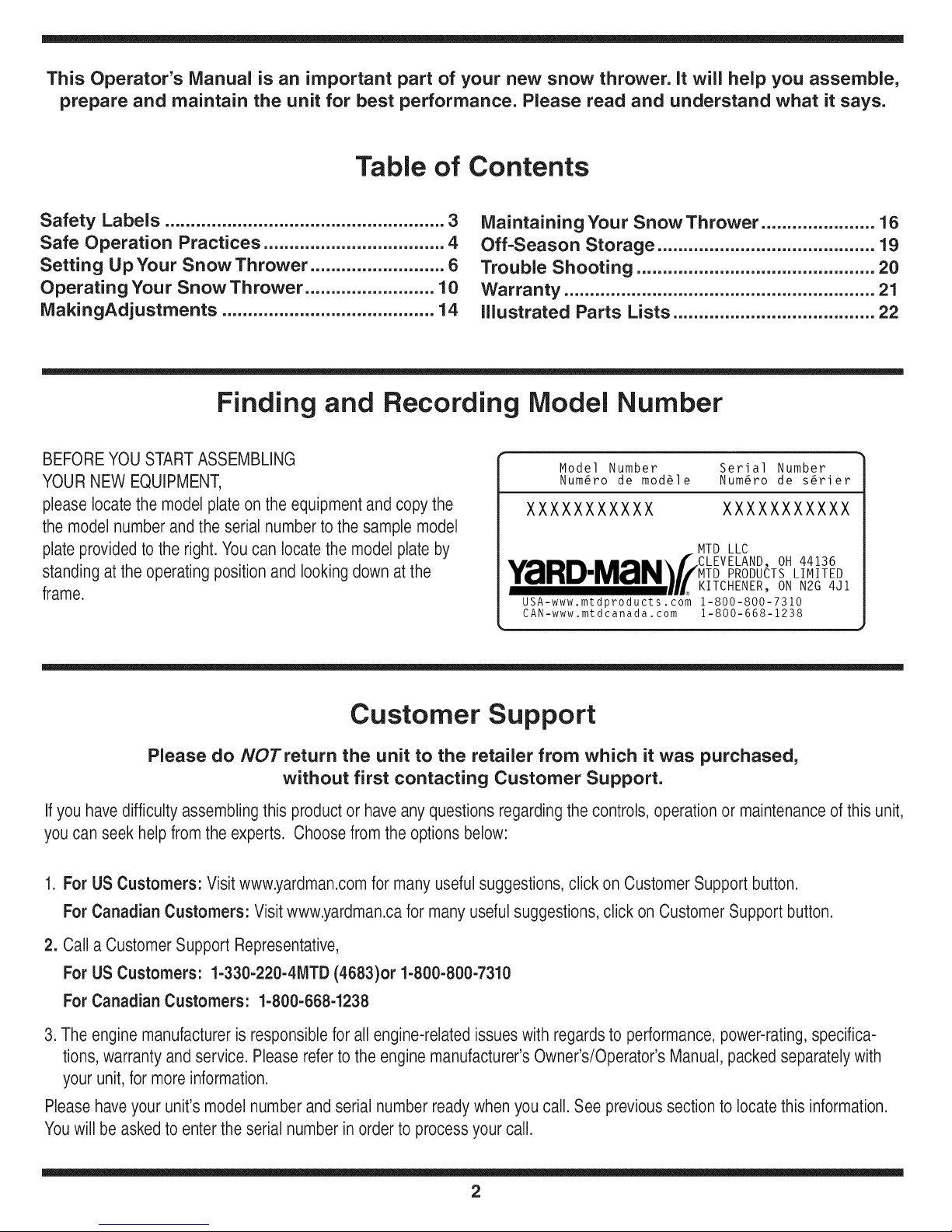
BEFOREYOU STARTASSEMBLING
YOURNEW EQUIPMENT,
please locatethe modelplate onthe equipmentand copythe
the modelnumber andthe serialnumbertothe sample model
plate providedto the right.You can locatethe model plate by
standing atthe operatingposition and looking downatthe
frame.
Maintaining Your Snow Thrower ...................... 16
Off-Season Storage .......................................... 19
Trouble Shooting .............................................. 20
Warranty ............................................................ 21
illustrated Parts Lists ....................................... 22
Model Number Serial Number
Num6ro de mod61e Num6ro de s6rier
XXXXXXXXXXX XXXXXXXXXXX
MTD LLC
PRODUCTS LIMITED
KITCHENER, ON N2G 4J1
USA-www.mtdproducts.com 1-800-800-7310
CAN-www.mtdcanada.com 1-800-668-1238
OH 44136
Customer Support
Please do NOTreturn the unit to the retailer from which it was purchased,
without first contacting Customer Support.
Ifyou havedifficulty assemblingthis productor haveanyquestions regardingthecontrols, operation or maintenanceof this unit,
youcan seek helpfromthe experts. Choose from the options below:
1. ForUSCustomers: Visit www.yardman.comfor many usefulsuggestions,click on CustomerSupport button.
ForCanadian Customers: Visit www.yardman.cafor manyusefulsuggestions,click on CustomerSupport button.
2. Call a CustomerSupport Representative,
ForUSCustomers: 1-330-220-4MTD (4683)or 1-800-800-7310
ForCanadianCustomers: 1-800-668-1238
3. The engine manufactureris responsiblefor allengine-relatedissueswith regardsto performance,power-rating,specifica-
tions,warranty andservice. Please referto the engine manufacturer'sOwner's/Operator's Manual,packedseparatelywith
your unit, for more information.
Pleasehaveyour unit's model number andserial numberreadywhenyou call. See previoussectionto locatethis information.
Youwill be askedto enter theserialnumber in order to processyour call.
2
Page 3
222
ChuteClean-out
Tool
CS00071
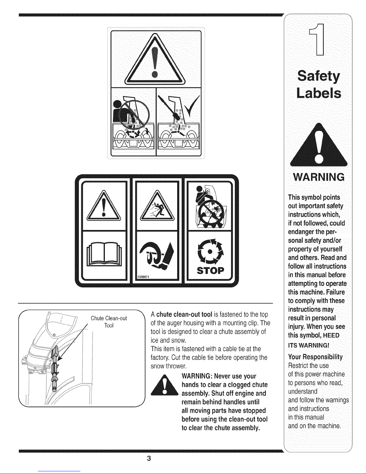
A chute clean-out tool isfastenedto the top
of the auger housingwith a mountingclip. The
tool isdesignedtoclear a chuteassembly of
ice and snow.
Thisitem is fastenedwitha cable tie atthe
factory.Cut the cable tie before operatingthe
snowthrower.
_ WARNING: Never use your
J
,m#
mmmmmmmmm
handsto clear a clogged chute
assembly. Shut off engine and
remain behind handles until
all moving parts havestopped
before using the clean-out tool
to clear the chute assembly.
STOP
WARNING
This symbol points
out importantsafety
instructionswhich,
ifnot followed, could
endanger the per-
sonal safety and/or
propertyof yourself
and others. Readand
follow all instructions
inthis manual before
_ttempting to operate
this machine. Failure
to comply with these
instructionsmay
result inpersonal
injury.When you see
this symbol, HEED
iTS WARNING!
four Responsibility
::restrictthe use
ofthis power machine
to persons who read,
understand
and follow thewarnings
and instructions
inthis manual
and on the machine.
3
Page 4
WARNING: EngineExhaust,some of its constituents, andcertain vehiclecompo-
nentscontain or emit chemicals knownto Stateof Californiato cause cancer and
birth defects or other reproductiveharm.
DANGER: This machinewas builtto beoperatedaccordingto the safeoperation practices in this
manual.As with any type of powerequipment,carelessnessor error onthe part ofthe operatorcan
result in seriousinjury.This machine is capable of amputatinghands andfeet andthrowing objects.
Failureto observethe followingsafety instructionscould resultin serious injuryordeath.
WARNING
Thissymbolpoints
outimportantsafety
instructionswhich,
ifnotfollowed, could
endangerthe per-
sonalsafetyand/or
propertyof yourself
andothers.Readand
followallinstructions
inthismanualbefore
attemptingto operate
thismachine.Failure
i to complywiththese
instructionsmay
; resultin personal
injury.Whenyou see
this symbol, HEED
iTS WARNING!
Your Responsibility
Restrictthe use
of this powermachine
to personswho read,
understand
I andfollow the warnings
and instructions
inthis manual
and on the machine.
Training
1. Read,understand,andfollowall instructionson the
machineandin themanual(s)beforeattemptingto
assembleandoperate.Keepthis manualina safe placefor
futureandregularreferenceandfor orderingreplacement
parts.
2. Befamiliarwithall controlsandtheirproperoperation.
Knowhowto stopthe machineanddisengagethemquickly.
3. Neverallowchildrenunder14yearsoldto operatethis
machine.Children14yearsold andovershouldreadand
understandtheinstructionsandsafeoperationpractices
inthismanualand onthemachineandbetrainedand
supervisedbyan adult.
4. Neverallowadultsto operatethis machinewithoutproper
instruction.
5. Thrownobjectscancauseseriouspersonalinjury.Plan
yoursnow-throwingpatternto avoiddischargeof material
towardroads,bystandersandthe like.
6. Keepbystanders,helpers,petsandchildrenat least75feet
fromthe machinewhileit isin operation.Stopmachineif
anyoneentersthearea.
7. Exercisecautiontoavoidslippingor falling,especially
whenoperatingin reverse.
Preparation
1. Thoroughlyinspectthe areawherethe equipmentisto be
used.Removealldoormats,newspapers,sleds,boards,
wiresand otherforeignobjects,whichcouldbetripped
overor thrownbythe auger/impeller.
2. Alwayswearsafetyglassesor eyeshieldsduring
operationandwhileperforminganadjustmentor repair
toprotectyoureyes.Thrownobjectswhich ricochetcan
causeseriousinjurytothe eyes.
3. Do notoperatewithoutwearingadequatewinteroutergar-
ments.Donotwearjewelry,longscarvesor otherloose
clothing,whichcouldbecomeentangledin movingparts.
Wearfootwearwhichwillimprovefootingonslippery
surfaces.
4. Useagroundedthree-wireextensioncordand receptacle
forall unitswithelectricstartengines.
5. Adjustcollectorhousingheightto cleargravel orcrushed
rocksurfaces.
6. Disengageallcontrolleversbeforestartingthe engine.
7. Neverattemptto makeanyadjustmentswhileengineis
running,exceptwherespecificallyrecommendedinthe
operator'smanual.
8. Letengineandmachineadjusttooutdoortemperature
beforestartingtoclearsnow.
Safe Handling of Gasoline
Toavoidpersonalinjuryorpropertydamageuseextremecare
in handlinggasoline.Gasolineisextremelyflammableandthe
vaporsareexplosive.Seriouspersonalinjurycanoccurwhen
gasolineisspilled onyourselfor yourclothes,whichcanignite.
Washyourskin andchangeclothesimmediately.
a. Useonlyanapprovedgasolinecontainer.
b. Extinguishallcigarettes,cigars,pipesandothersources
ofignition.
c. Neverfuelmachineindoors.
d. Neverremovegascap oraddfuelwhilethe engineis hot
or running.
e. Allowengineto coolat leasttwo minutesbeforerefuel-
ing.
f. Neveroverfill fueltank. Filltankto nomorethanY2inch
belowbottomoffiller neckto providespacefor fuel
expansion.
g. Replacegasolinecap andtightensecurely.
h. If gasolineis spilled,wipe itoff theengineand equip-
ment.Movemachinetoanotherarea.Wait5 minutes
beforestartingtheengine.
i. Neverstorethe machineorfuel containerinside where
there isan openflame,sparkor pilotlight(e.g.furnace,
waterheater,spaceheater,clothesdryeretc.).
j. Allowmachinetocoolat least5 minutesbeforestoring.
4
Page 5

Operation
1. Donot puthandsorfeetnearrotatingparts,inthe
auger/impellerhousingor chuteassembly.Contactwiththe
rotatingpartscanamputatehandsandfeet.
2. The auger/impellercontrolleveris asafetydevice.Never
bypassitsoperation.Doingso makesthe machineunsafe
andmaycausepersonalinjury.
3. The controlleversmustoperateeasilyin bothdirections
andautomaticallyreturntothe disengagedpositionwhen
released.
4. Neveroperatewitha missingor damagedchuteassembly.
Keepall safetydevicesinplaceandworking.
5. Neverrunan engineindoorsor in apoorlyventilatedarea.
Engineexhaustcontainscarbonmonoxide,anodorlessand
deadlygas.
6. Donotoperatemachinewhileunderthe influenceofalcohol
or drugs.
7. Mufflerandenginebecomehotandcan causea burn.Do
nottouch.
8. Exerciseextremecautionwhenoperatingonor crossing
gravelsurfaces.Stayalertfor hiddenhazardsortraffic.
9. Exercisecautionwhenchangingdirectionandwhileoperat-
ingonslopes.
10.Planyoursnow-throwingpatternto avoiddischargetowards
windows,walls,carsetc.Thus,avoidingpossibleproperty
damageor personalinjury causedby aricochet.
11.Neverdirectdischargeatchildren,bystandersand petsor
allow anyoneinfrontofthe machine.
12.Donotoverloadmachinecapacitybyattemptingto clear
snowattoofast of arate.
13.Neveroperatethis machinewithoutgoodvisibility or light.
Alwaysbe sureofyourfootingandkeepa firmholdonthe
handles.Walk,neverrun.
14.Disengagepowerto the auger/impellerwhentransportingor
notinuse.
15.Neveroperatemachineat hightransport speedsonslippery
surfaces.Lookdownand behindandusecare when
backingup.
16.Ifthe machineshouldstartto vibrateabnormally,stopthe
engine,disconnectthesparkplugwireand groundit against
the engine.Inspectthoroughlyfordamage.Repairany
damagebeforestartingandoperating.
17.Disengageallcontrolleversandstopenginebeforeyou
leavethe operatingposition(behindthe handles).Wait
untilthe auger/impellercomestoa completestopbefore
uncloggingthe chuteassembly,makinganyadjustments,or
inspections.
18.Neverputyourhandin thedischargeor collectoropenings.
Alwaysuse theclean-outtoolprovidedtounclogthe dis-
chargeopening.Donot unclogchuteassemblywhileengine
isrunning.Shut offengineandremainbehindhandlesuntil
all movingpartshavestoppedbefore unclogging.
19.Useonly attachmentsandaccessoriesapprovedbythe
manufacturer(e.g.wheelweights,tirechains,cabsetc.).
20. Ifsituationsoccurwhich arenotcoveredin thismanual,use
careand goodjudgment.Callcustomerassistanceforthe
nameof yournearestservicingdealer.
Maintenance & Storage
1. Nevertamperwithsafetydevices.Checktheir proper
operationregularly.Refertothe maintenanceandadjust-
mentsectionsofthis manual.
2. Beforecleaning,repairing,orinspectingmachinedisengage
allcontrolleversandstopthe engine.Waituntilthe
auger/impellercometo a completestop.Disconnectthe
sparkplugwireand groundagainsttheengineto prevent
unintendedstarting.
3. Checkbolts andscrewsfor propertightnessatfrequent
intervalstokeepthe machineinsafeworkingcondition.
Also,visuallyinspectmachinefor anydamage.
4. Do notchangetheenginegovernorsettingor over-speed
theengine.The governorcontrolsthemaximumsafe
operatingspeedoftheengine.
5. Snowthrowershaveplatesandskidshoesaresubjectto
wearanddamage.Foryoursafetyprotection,frequently
checkallcomponentsandreplacewith originalequipment
manufacturer's(OEM) partsonly."Useof partswhichdo
notmeetthe originalequipmentspecificationsmayleadto
improperperformanceandcompromisesafety!"
6. Checkcontrolsperiodicallytoverify theyengageand
disengageproperlyandadjust,if necessary.Referto the
adjustmentsectioninthis operator'smanualfor instructions.
7. Maintainor replacesafetyandinstructionlabels,as neces-
sary.
8. Observeproperdisposallawsandregulationsfor gas,oil,
etc.toprotectthe environment.
9. Priorto storing,runmachineafew minutestoclearsnow
frommachineandpreventfreezeupof auger/impeller.
10.Neverstorethemachineorfuel containerinsidewhere
thereisan openflame,sparkor pilotlightsuchas a water
heater,furnace,clothesdryeretc.
11.Alwaysreferto theoperator'smanualforproperinstructions
onoff-seasonstorage.
Do not modify engine
Toavoidseriousinjuryordeath,donot modifyengineinany
way.Tamperingwiththegovernorsettingcan leadto a runaway
engineandcauseit tooperateat unsafespeeds.Nevertamper
withfactorysettingofenginegovernor.
Notice regarding Emissions
Engineswhicharecertifiedto complywithCaliforniaandfederal
EPAemissionregulationsforSORE(SmallOff RoadEquipment)
arecertifiedto operateonregularunleadedgasoline,andmay
includethefollowingemissioncontrolsystems:EngineModifica-
tion(EM)andThreeWayCatalyst(TWO)ifso equipped.
Average Useful Life
Accordingto the ConsumerProductsSafetyCommission
(CPSC)andthe U.S.EnvironmentalProtectionAgency(EPA),
thisproducthasanAverage UsefulLife ofseven(7)years,or
60hoursof operation.Attheend oftheAverage UsefulLife,
buya newmachineorhavethe machineinspectedannuallyby
anauthorizedservicedealertoensurethat all mechanicaland
safetysystemsare workingproperlyandnotwornexcessively.
Failuretodosocanresultin accidents,injuriesordeath.
WARNING
This symbol points
out important safety
instructions,which
if not followed, could
endanger the per-
sonalsafety and/or
property of yourself
and others. Read and
follow all instructions
in this rnanuai before
attempting to operate
this machine. Failure
to complywith these
instructionsmay
result in personal
injury.When you see
this symbol, HEED
IT'S WARNING!
Your Responsibility
Restrictthe use
ofthis powermachine
to personswho read,
understand
and followthe warnings
and instructions
in this manual
and on the machine.
5
Page 6
NOTE:Referencesto
rightorleftsideofthe
snowthroweraredeter-
minedfrombehindthe
unitintheoperating
position.
Figure 3-1
IMPORTANT:Thesnowthrowerisshippedwithoil
andWITHOUTGASOLINE.Afterassembly,referto
separateenginemanualfor properfuelandengineoil
recommendations.
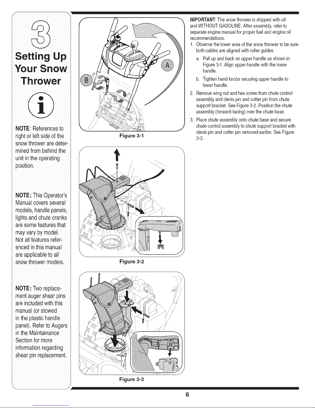
1. Observethelowerareaof thesnowthrowerto be sure
bothcablesarealignedwithrollerguides.
a. Pullupand backon upperhandleas shownin
Figure3-1.Alignupperhandlewiththelower
handle.
b. Tightenhandknobssecuringupperhandleto
lowerhandle.
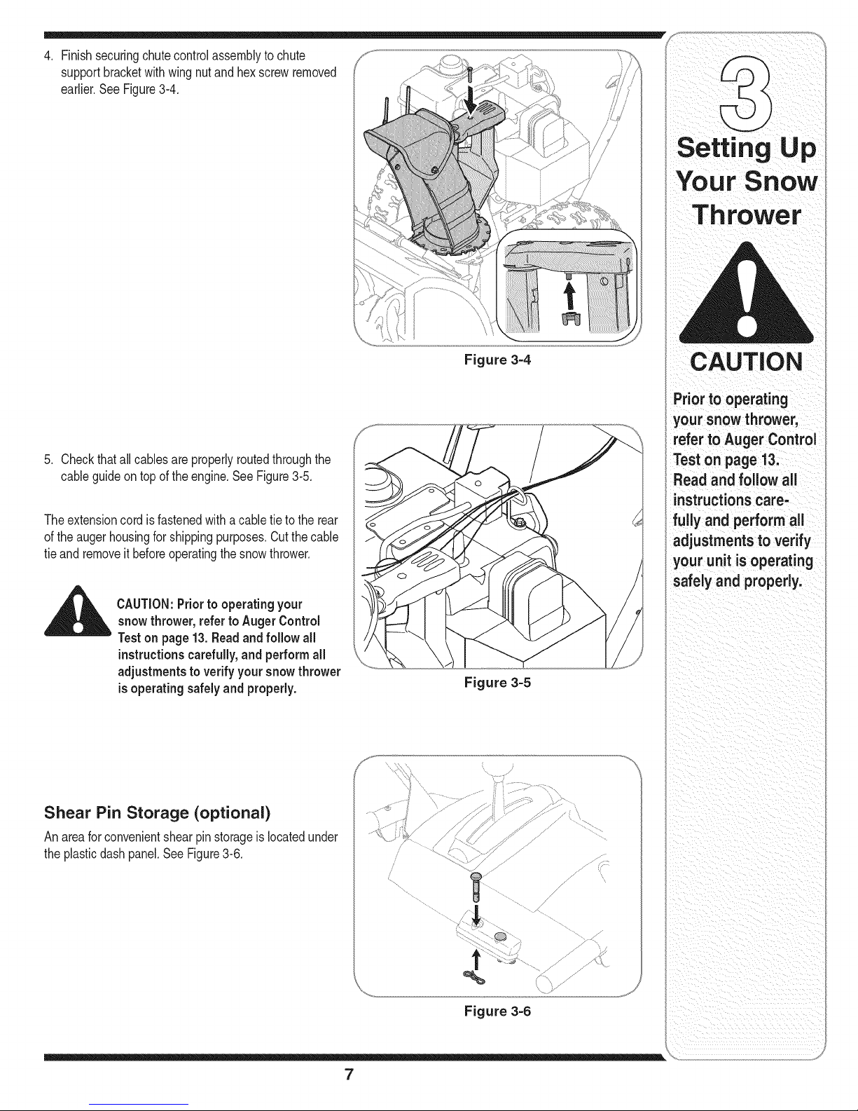
2. Removewingnutand hexscrewfromchutecontrol
assemblyandclevispinandcotter pinfromchute
supportbracket.SeeFigure3-2.Positionthechute
assembly(forward-facing)overthechutebase.
3. Placechuteassemblyontochutebaseand secure
chutecontrolassemblytochutesupportbracketwith
clevispinandcotterpin removedearlier.SeeFigure
3-3.
NOTE:ThisOperator's
Manualcoversseveral
models,handlepanels,
lightsandchutecranks
aresomefeaturesthat
mayvarybymodel.
Notallfeaturesrefer-
encedinthismanual
areapplicabletoall
snowthrowermodels.
NOTE:Tworeplace-
mentaugershearpins
areincludedwiththis
manual(orstowed
i intheplastichandle
panel).RefertoAugers
, intheMaintainance
i Sectionformore
informationregarding
shearpinreplacement.
Figure 3=2
Figure 3=3
6
Page 7
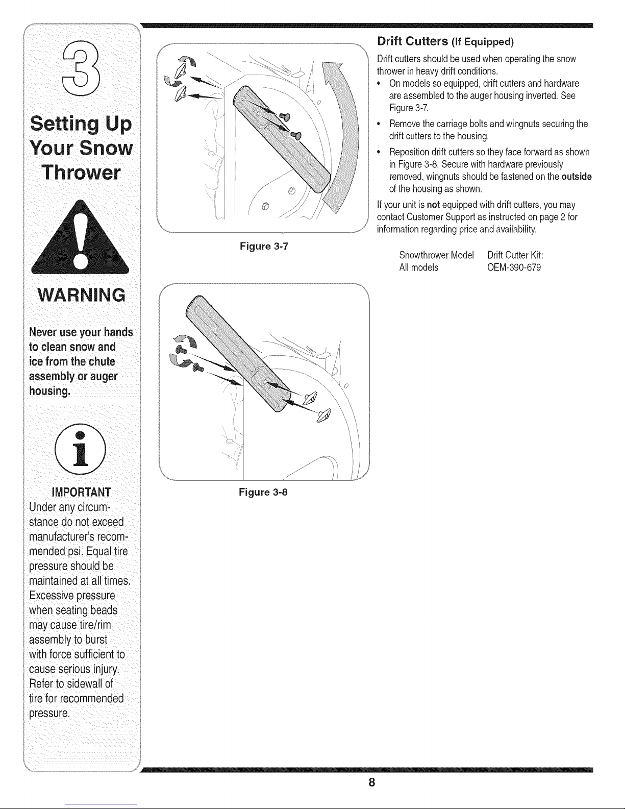
4. Finishsecuringchutecontrolassemblytochute
supportbracketwithwingnutandhexscrewremoved
earlier.SeeFigure3-4.
Setting U p
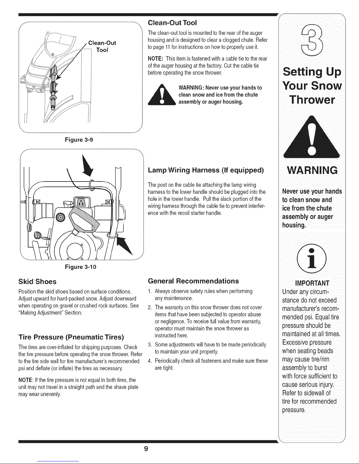
5. Checkthatall cablesareproperlyroutedthroughthe
cableguideon topofthe engine.SeeFigure3-5.
Theextensioncordis fastenedwitha cabletieto the rear
ofthe augerhousingforshippingpurposes.Cutthecable
tieand removeit beforeoperatingthesnowthrower.
CAUTION:Priorto operating your
snowthrower, referto AugerControl
Teston page13. Readand follow all
instructionscarefully,and performall
adjustments to verify your snowthrower
isoperating safely and properly.
Figure 3=4
Figure 3=5
CAUTION
Priorto operating
your snow thrower,
refer to Auger Control
Test on page 13.
Read and follow all
instructionscare-
fully and perform all
adjustments to verify
your unit is operating
safely and properly.
Shear Pin Storage (optional)
An areaforconvenientshearpin storageis locatedunder
theplasticdashpanel.SeeFigure3-6.
/
/Y
,%
Figure 3=6
7
Page 8
WARNING
Neveruseyourhands
to cleansnowand
icefromthe chute
assemblyorauger
housing.
Figure 3=7
Drift Cutters (If Equipped)
Driftcuttersshouldbeusedwhenoperatingthesnow
throwerinheavydriftconditions.
Onmodelssoequipped,driftcuttersand hardware
areassembledto theaugerhousinginverted.See
Figure3-7.
• Removethecarriageboltsandwingnutssecuringthe
driftcutterstothe housing.
• Repositiondriftcutterssotheyfaceforwardas shown
in Figure3-8.Securewithhardwarepreviously
removed,wingnutsshouldbefastenedon theoutside
ofthe housingasshown.
If yourunit isnot equippedwithdrift cutters,youmay
contactCustomerSupportas instructedonpage2 for
informationregardingpriceand availability.
SnowthrowerModel Drift CutterKit:
Allmodels 0EM-390-679
iMPORTANT
Underany circum-
stance do not exceed
manufacturer'srecom-
mendedpsi. Equaltire
pressureshouldbe
maintainedat all times.
i Excessivepressure
whenseatingbeads
maycausetire/rim
assemblyto burst
with forcesufficientto
cause seriousinjury
Referto sidewallof
tirefor recommended
pressure.
Figure 3=8
8
Page 9
Clean=Out
Tool
Clean-Out Tool
Theclean-outtool ismountedtotherearof theauger
housingandis designedtocleara cloggedchute.Refer
topage11for instructionson howtoproperlyuseit.
NOTE: This itemisfastenedwithacabletie to therear
ofthe augerhousingatthefactory.Cutthecabletie
beforeoperatingthesnowthrower.
Figure 3-9
_ ARNING:Neveruse yourhandsto
_jJ_
clean snowand ice from the chute
assembly or auger housing.
Lamp Wiring Harness (If equipped)
Theposton the cabletie attachingthelampwiring
harnessto the lowerhandleshouldbe pluggedintothe
holeinthelowerhandle. Pullthe slackportionofthe
wiringharnessthroughthecabletieto preventinterfer-
encewiththe recoilstarterhandle.
ThrOWer
WARNING
Never use your hands
to clean snow and
ice from the chute
assembly or auger
housing,
Figure 3-10
Skid Shoes
Positiontheskidshoesbasedon surfaceconditions. 1.
Adjustupwardforhard-packedsnow.Adjustdownward
whenoperatingon gravelorcrushedrocksurfaces.See 2.
"MakingAdjustment"Section.
Tire Pressure (Pneumatic Tires)
Thetiresareover-inflatedforshippingpurposes.Check
thetire pressurebeforeoperatingthesnowthrower.Refer
tothe tiresidewallfor tiremanufacturer'srecommended
psianddeflate(or inflate)thetiresas necessary.
NOTE:Ifthetire pressureisnot equalinbothtires, the
unitmaynottravelina straightpathandtheshaveplate
maywearunevenly.
General Recommendations
Alwaysobservesafetyruleswhenperforming
anymaintenance.
Thewarrantyon thissnowthrowerdoesnotcover
itemsthathavebeensubjectedtooperatorabuse
or negligence.Toreceivefullvaluefromwarranty,
operatormustmaintainthe snowthroweras
instructedhere.
3. Someadjustmentswillhaveto bemadeperiodically
tomaintainyourunitproperly.
4. Periodicallycheckall fastenersand makesurethese
aretight.
i _ i i i
iMPORTANT
Underanycircum:
stance do not exceed
manufactureCs recom_
mended psL EqUaltire
pressure shouldbe
maintainedat alltimes:
Excessive pressure
when seating beads
may causetireirim
assembly toburSt
with forcesufficientto
cause seriousinjuryl
Refer tosidewallof
tire for rec0mmended
pressure:
9
Page 10

ThrOWer
WARNING
Read,understand,
andfollow allinstruc-
tions andwarnings
onthe machineand
inthis manualbefore
operating.
Useextreme care
hen handling
gasoline.Gasoline is
extremelyflammable
andthe vapors are
explosive.Neverfuel
the machineindoors
or while the engine
is hot or running.
Extinguishcigarettes,
cigars,pipes and
other sourcesof
ignition.
HeatedHandles
Switch (en option)l-
Headlight_ WheelSteering
Electric Start
GasCa
Oil EngineControls
]ool
1 If Equipped Shoe Control
Figure 4-1
Nowthatyouhavesetup yoursnowthrowerfor opera-
tion,getacquaintedwithits controlsandfeatures.These
aredescribedbelowandillustrated in Figure4-1.This
knowledgewillallow youto useyournewequipmentto
itsfullestpotential.
NOTE: Fordetailedstartinginstructionsandmore
informationonall enginecontrols,refertothe separate
enginemanualpackedwithyour unit.
Shift Lever
Theshiftleveris locatedon therightside
ofthe handlepanel.Placetheshift lever
intoany ofeightpositionstocontrolthe 4,
directionof travelandgroundspeed.
Forward 3
Yoursnowthrowerhassixforward(F)
speeds,withpositionnumberone (1) t 2
beingtheslowestspeed.
Reverse 1
Yoursnowthrowerhastwo reverse(R)
speeds,withpositionnumberone (1) R 1
beingtheslowerspeed.
6
Choke Control
Thechokecontrolis foundonthe rearofthe engineand
isactivatedby rotatingtheknobclockwise.Activatingthe
chokecontrolclosesthe chokeplateon thecarburetor
andaidsinstartingtheengine.
Throttle Control
Thethrottlecontrolis locatedonthe engine.
it regulatesthespeedof theengineand
willshutoff the enginewhenpusheddown
completely.
Primer
Depressingthe primerforcesfueldirectly
intothe engine'scarburetortoaidin cold-
weatherstarting.
Oil Fill
Engineoil levelcanbecheckedandoil
addedthroughtheoil fill.
R2
Drive Control
.Shift Lever
Four-Way
Chute ControlTM
uger Control
Control 1
RecoilStarter
Handle
ElectricStarterOutlet
Ignition
Key
X
Choke
Control
Throttle
• J
III
10
Page 11
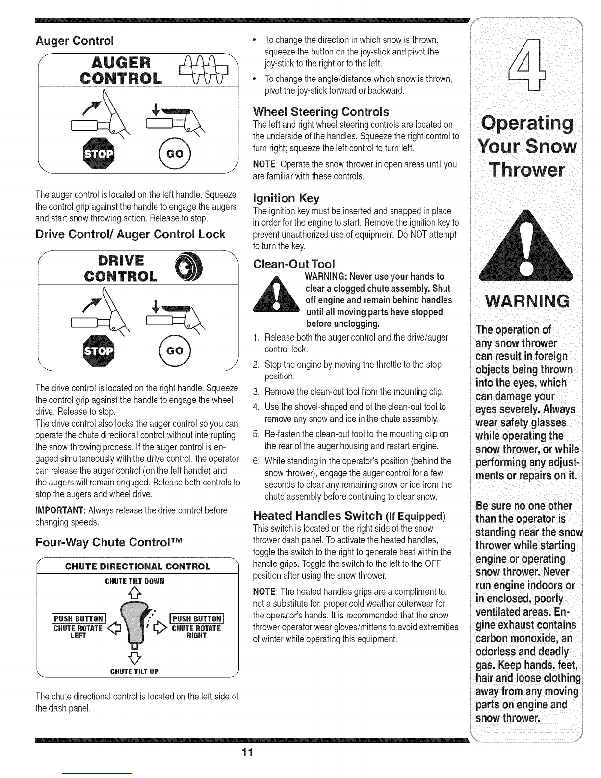
Auger Control
f
* Tochangethedirectioninwhichsnowis thrown,
squeezethe buttononthejoy-stickandpivotthe
joy-stickto the rightorto theleft.
* Tochangetheangle/distancewhichsnowisthrown,
pivotthejoy-stickforwardor backward.
Wheel Steering Controls
Theleftand rightwheelsteeringcontrolsare locatedon
theundersideofthe handles.Squeezetherightcontrolto
turnright;squeezetheleftcontroltoturnleft.
NOTE:Operatethesnowthrowerinopenareas untilyou
arefamiliarwiththesecontrols.
Operating
Snow
Throwe r
Theaugercontrolis locatedontheleft handle.Squeeze
thecontrolgripagainstthe handletoengagetheaugers
andstartsnowthrowingaction.Releasetostop.
Drive Control/Auger Control Lock
f DRIVE -X
CONTROL
Thedrivecontrolislocatedonthe righthandle.Squeeze
thecontrolgripagainstthe handletoengagethewheel
drive.Releasetostop.
Thedrivecontrolalsolockstheaugercontrolsoyoucan
operatethechutedirectionalcontrolwithoutinterrupting
thesnowthrowingprocess.Ifthe augercontrolisen-
gagedsimultaneouslywiththedrivecontrol,theoperator
canreleasetheaugercontrol(onthe lefthandle)and
theaugerswillremainengaged.Releasebothcontrolsto
stoptheaugersandwheeldrive.
iMPORTANT:Alwaysreleasethedrivecontrolbefore
changingspeeds.
Four-Way Chute Control TM
f
CHUTE DiRECTiONAL CONTROL
CHUTETILTDOWN
jPUSH BUTTOHi
CHUTEROTATE
RIGHT
CHUTETiLTUP j
Thechutedirectionalcontrolislocatedon theleftside of
thedash panel.
Ignition Key
Theignitionkeymustbe insertedandsnappedinplace
inorderforthe enginetostart. Removetheignitionkeyto
preventunauthorizeduseof equipment.DoNOTattempt
toturn thekey.
Clean-Out Tool
WARNING:Neveruseyour handsto
clear aclogged chute assembly.Shut
off engine and remain behind handles
until ail moving partshavestopped
before unclogging.
1.
Releaseboththe augercontroland thedrive/auger
controllock.
2.
Stoptheenginebymovingthethrottleto thestop
position.
3.
Removethe clean-outtoolfromthe mountingclip.
4.
Usetheshovel-shapedendofthe clean-outtoolto
removeanysnowandice inthechuteassembly.
5.
Re-fastentheclean-outtoolto themountingclipon
therearof theaugerhousingand restartengine.
6.
Whilestandingin theoperator'sposition(behindthe
snowthrower),engagethe augercontrolfora few
secondsto clearanyremainingsnoworicefromthe
chuteassemblybeforecontinuingtoclearsnow.
Heated Handles Switch (if Equipped)
Thisswitchis locatedonthe rightside ofthe snow
throwerdashpanel.Toactivatethe heatedhandles,
togglethe switchtothe rightto generateheatwithinthe
handlegrips.Toggletheswitchtothe lefttothe OFF
positionafterusingthe snowthrower.
NOTE:Theheatedhandlesgripsarea complimentto,
nota substitutefor,propercoldweatherouterwearfor
theoperator'shands.Itis recommendedthatthesnow
throweroperatorweargloves/mittensto avoidextremities
ofwinterwhile operatingthis equipment.
WARNING
The operation of
any snow thrower
can result inforeign
objects being thrown
intothe eyes, which
can damage your
eyes severely. Always
wear safety glasses
while operating the
snow thrower, or while
performing any adjust-
ments or repairs on it.
Besure no oneother
than the operator is
standing near the sno_
thrower while starting
engine or operating
snow thrower. Never
run engine indoors or
in enclosed, poorly
ventilated areas. En-
gine exhaust contains
carbon monoxide, an
odorless and deadly
gas. Keep hands, feet,
hair and loose clothing
away from any moving
parts on engine and
snow thrower.
11
Page 12

WARNING
Gas & Oil Fill-Up
Servicetheenginewithgasolineandoil asinstructedin
theseparateenginemanualpackedwithyourunit.Read
instructionscarefully.
Starting The Engine
1. Attachsparkplugwireto sparkplug.Makecertainthe
metalloopon theendof thesparkplugwire (inside
therubberboot)isfastenedsecurelyoverthe metal
tiponthe sparkplug.
2. Makecertainboththeaugercontrolanddrivecontrol
arein thedisengaged(released)position.
3. Movethrottlecontrolupto FASTposition.Insert
ignitionkeyinto slot.Makesureitsnapsintoplace.
Donotattempttoturn thekey.
7. Whendisconnectingtheextensioncord,always
unplugtheendat thethree-prongwalloutletbefore
unpluggingtheoppositeendfromthe snowthrower.
Recoil Starter
1. Rotatechokecontrolto FULLchokeposition(cold
enginestart).
NOTE:If theengineis alreadywarm,placechokecontrol
intheOFFpositioninsteadof FULL.
2. Pushthe primertwoor threetimesforcoldengine
start,makingsureto coverventholeinthecenterof
theprimerwhenpushing.
NOTE:DO NOTuseprimerto restarta warmengine
aftera shortshutdown.
Read, understand,
and follow all instruc-
tions and warnings
on the machineand
inthis manual before
operating.
Useextreme care
when handling
gasoline.Gasoline is
extremelyflammable
and the vapors are
explosive.Neverfuel
the machine indoors
or while the engine
is hot or running.
Extinguishciga-
rettes, cigars, pipes
and other sources of
ignition.
Ifyour home'swiring
systemis not a
three-wire grounded
system,do not use
this electric starter
under any condi-
tions.
If your home
electricalsystem
is grounded,
but a three-hole
receptacleis not
available, do not use
yoursnow throweCs
electricstarter.
NOTE:The enginecannotstartunlessthe keyis
insertedintoignitionswitch.
Electric Starter
1. Determinethatyourhome'swiringis a three-wire
groundedsystem.Ask a licensedelectricianifyouare
notcertain.
WARNING:Theoptional electricstarter
isequippedwith a grounded three-wirepowercordand plug,and is designed
to operate on 120voltAC household
current.It must beused with a properly
grounded three-prong receptacle atall
times to avoidthe possibilityof electric
shock.Followall instructionscarefully
priorto operating the electric starter,
ifyouhavea groundedthree-prongreceptacle,proceed
asfollows:
1. Plugtheextensioncordintothe outletlocatedon the
engine'ssurface.Plugtheotherendofextensioncord
intoa three-prong120-volt,grounded,ACoutletina
well-ventilatedarea.
2. RotatechokecontroltoFULLchokeposition(fora
coldenginestart).
NOTE:Ifthe engineisalreadywarm,placechokecontrol
inthe OFFpositioninsteadofFULL.
3. Pushtheprimertwoor threetimesforcoldengine
start,makingsureto coverventholein thecenterof
theprimerwhenpushing.
NOTE:DONOTuseprimertorestartawarmengine
aftera shortshutdown.
4. Pushstarterbuttonto startengine.
5. Oncetheenginestarts,immediatelyreleasestarter
button.
6. As theenginewarms,slowlyrotatethechokecontrol
tothe OFFposition.Ifthe enginefalters,quickly
rotatethechokecontrolbackto FULLand thenslowly
intothe OFFpositionagain.
NOTE:Additionalprimingmaybe necessaryifthe
temperatureis below150Fahrenheit.
3. Graspthe recoilstarterhandleandslowlypullthe
ropeout.Atthe pointwhereitbecomesslightlyharder
topullthe rope,slowlyallowthe ropeto recoil.
4. Pullthe starterhandlewithafirm,rapidstroke.Donot
releasethehandleandallowitto snapback.Keepa
firmholdon thestarterhandleandallowitto slowly
recoil.
.
Asthe enginewarms,slowlyrotatethe chokecontrol
tothe OFFposition.Ifthe enginefalters,quicklyrotate
thechokecontrolbackto the FULLpositionandthen
slowlyintotheOFFpositionagain.
NOTE:Allowtheengineto warmup fora few minutes
afterstarting.Theenginewill notdevelopfull poweruntil
itreachesoperatingtemperatures.
Stopping The Engine
Runenginefor a fewminutesbeforestoppingtohelpdry
offanymoistureontheengine.
Tohelppreventpossiblestarterfreeze-up,proceedas
follows:
Electric Starter (if Equipped)
1. Connectextensioncordtothe electricstarteroutlet
ontheengine,thento 120voltACoutlet.
2. Withthe enginerunning,pushthestarterbuttonand
allowthe starterforspinfor severalseconds.The
noisemadebythe starteris normal.Theengine's
starteris notbeingharmed.
3. Whendisconnectingtheextensioncord,always
unplugtheendat thethree-prongwalloutletbefore
unpluggingtheoppositeendfromthe snowthrower.
4. MovethrottlecontroltoSTOPposition.
5. Removetheignitionkey(Donotturnkey)to prevent
unauthorizeduseof equipment.
6. Wipeallsnowandmoisturefromtheareaaroundthe
engineaswell asthe areainandaroundthedrive
controlandaugercontrol.Also,engageandrelease
bothcontrolsseveraltimes.
12
Page 13

NOTE:Keepthe keyin a safeplace.Theenginecannot
startwithouttheignitionkey.
Recoil Starter
1. Withenginerunning,pullstarterropewitha rapid,
continuousfull armstrokethreeor fourtimes.Pulling
thestarterropewillproducea loudclatteringsound,
whichisnotharmfultoengine.
2. MovethrottlecontroltoSTOPposition.
3. Removethe ignitionkey(Donotturnkey)to prevent
unauthorizeduseof equipment.
NOTE:Keepthe keyin a safeplace.Theenginecannot
startwithouttheignitionkey.
4. Wipeall snowandmoisturefromtheareaaroundthe
engineaswellasthe areain andaroundthedrive
controlandaugercontrol.Also,engageand release
bothcontrolsseveraltimes.
To Engage Drive
Withtheenginerunningneartop speed,move
shiftleverto oneof sixFORWARDpositionsor two
REVERSEpositions.Selecta speedappropriatefor
thesnowconditionsthatexist.
2. Squeezedrivecontrolagainstthe righthandleand
thesnowthrowerwill move.Releaseitandthedrive
motionwillstop.
3. Toturnthe unitleftorright,squeezetherespective
wheelsteeringcontrol.SeeFigure4-1.
2. Ina well-ventilatedarea,startthesnowthrower
engineasinstructedonthe previouspage.Makesure
thethrottleissetin the FASTposition.
3. Whilestandingin theoperator'sposition(behindthe
snowthrower),engagethe auger.
4. Allowtheaugerto remainengagedforapproximately
ten(10)secondsbeforereleasingtheaugercontrol.
Repeatthisseveraltimes.
5. Withthe throttlecontrolin the FAST(rabbit)position
andtheaugercontrolinthe disengaged"up"position,
walktothe frontofthe machine.
6. Confirmthattheaugerhascompletelystopped
rotatingandshowsNOsignsofmotion.Iftheauger
showsANYsignsofrotating,immediatelyreturnto
theoperator'spositionandshutofftheengine.Wait
forALLmovingpartsto stopbeforere-adjustingthe
augercontrol.
7. To readjustthecontrolcable,loosentheupperhex
nutonthe augercablebracket.
8. Positionthebracketupwardtoprovidemoreslack(or
downwardtoincreasecabletension).SeeFigure4-2.
9. Retightentheupperhex nut.
10.RepeatAugerControlTesttoverifyproperadjustment
hasbeenachieved.
WARNING
Never use your hands
tocleansnowand
ice from the chute
assembly orauger
The muffler, engine
and surrounding
areas become hot
and can cause a
burn, Do not touch,
To Engage Augers
1. Toengageaugersandstartsnowthrowing,squeeze
thelefthandaugercontrolagainstthe left handle.
Releaseto stopaugers.
2. Whiletheaugercontrolis engaged,squeezethe drive
controltomove,releasetostop.Donotshiftspeeds
whilethe driveis engaged.
NOTE:Thissameleveralsolocksaugercontrolsoyou
canturn thechutecontrolwithoutinterruptingthesnow
throwingprocess.
3. Releasetheaugercontrol;the interlockmechanism
shouldkeeptheaugercontrolengageduntilthedrive
controlis released.
.
Releasethedrivecontrolto stopboththeaugersand
thewheeldrive.Tostoptheauger,bothleversmust
be released.
Auger Control Test
Performthefollowingtestbeforeoperatingyoursnow
throwerforthe firsttimeandat thestartofeachwinter.
Checktheadjustmentofthe augercontrolasfollows:
1. Whentheaugercontrolis releasedandinthe
disengaged"up"position,thecableshouldhavevery
littleslack.It shouldNOTbetight.
When selecting a
Drive Speed, usethe
slower speeds until
!ou are comfortable
and familiar with the
operation of the snow
thrower.
Figure 4=2
NEVERreposition the
shift lever(change
speeds or direction
of travel) without first
releasing the drive
control and bringing
the snow thrower
to a complete stop.
Doingso will result in
_remature wear to the
snow thrower's drive
system.
13
Page 14

Shift Cable
If thefull rangeofspeeds(forwardandreverse)cannot
beachieved,refertothe figureto theleftandadjustthe
shiftcable asfollows:
1. Placetheshiftleverin the fastest forwardspeed
position.
2. Loosenthehex nuton the shiftcableindexbracket.
SeeFigure5-1.
3. Pivotthe bracketdownwardtotakeupslackinthe
cable.
4. Retightenthehex nut.
5. Checkforcorrectadjustmentbeforeoperatingthe
snowthrower.
WARNING
Read, understand,
and follow all instruc-
tions and warnings
on the machine and
inthis manual before
operating.
i Never attempt to
make any adjust-
i merits whilethe
engine is running,
i exceptwhere speci-
fied in operator's
' manual.
Figure 5=1
Figure 5=2
Figure 5=3
Chute Control
Oncea seasonorevery25hoursofoperation,whichever
isearlier,checkwhetherthe four-waychutecontroFM
cableshaveslackened,ifthechutedoesnotrotate
fullyor itspitchcannotbe movedupordown,the chute
controlcableswillhavetobeadjusted.
Toadjustthesecables,proceedasfollows:
1. Totightencable,loosenthetopnutand tightenthe
bottomnuton thecable.
2. Adjustequallyon bothsidesby workingonboth
cables.SeeFigure5-2.
Drive Control & Shift Lever
Whenthedrivecontrolis releasedandin thedisengaged
"up"position,thecableshouldhaveverylittleslack.It
shouldNOTbetight.
Checktheadjustmentofthe drivecontrolas follows:
1. Withthe drivecontrolreleased,pushthesnowthrower
gentlyforward.Theunitshouldrollfreely.
2. Engagethedrivecontrolandgentlyattemptto push
thesnowthrowerforward.Thewheelsshouldnotturn.
Theunit shouldnot rollfreely.
3. Withthe drivecontrolreleased,movetheshiftlever
backandforthbetweentheR2 positionandtheF6
positionseveraltimes.Thereshouldbeno resistance
in theshift lever.
4. If anyofthe abovetestsfailed,thedrivecable isin
needofadjustment.Proceedasfollows:
5. Loosenthelowerhexnutonthedrivecablebracket.
SeeFigure5-3.
6. Positionthebracketupwardtoprovidemoreslack(or
downwardto increasecabletension).
7. Retightenthelowerhexnut.
Youcanalsocheckthe adjustmentasfollows:
1. Withthe snowthrowertippedforward(becertainto
draingasolineorplace plasticfilmunderthe gascap if
thesnowthrowerhasalreadybeenoperated),remove
theframecoverunderneaththesnowthrowerby
J
removingtheself-tappingscrews. SeeFigure6-5on
page17.
14
Page 15
2. Withthe drivecontrolreleased,theremustbe 1/8"
clearancebetweenthefrictionwheelandthe drive
pulleyin all positionsof theshiftlever.
3. Withthe drivecontrolengaged,thefrictionwheelmust
contactthedrive pulley.SeeFigure6-8.
4. Ifadjustmentisnecessary,loosenthelowerhexnut
on thedrivecableindexbracketandpivotthe bracket
upwardordownwardasnecessary.Referto Figure
5-3.Tightenthe lowerhexnutto securethebracket
whencorrectadjustmentisreached.
5. Reassembletheframecoverandreturntheunitback
to itsoperatingposition.
NOTE:if youplacedplasticunderthe gascap,becertain
to removeit now.
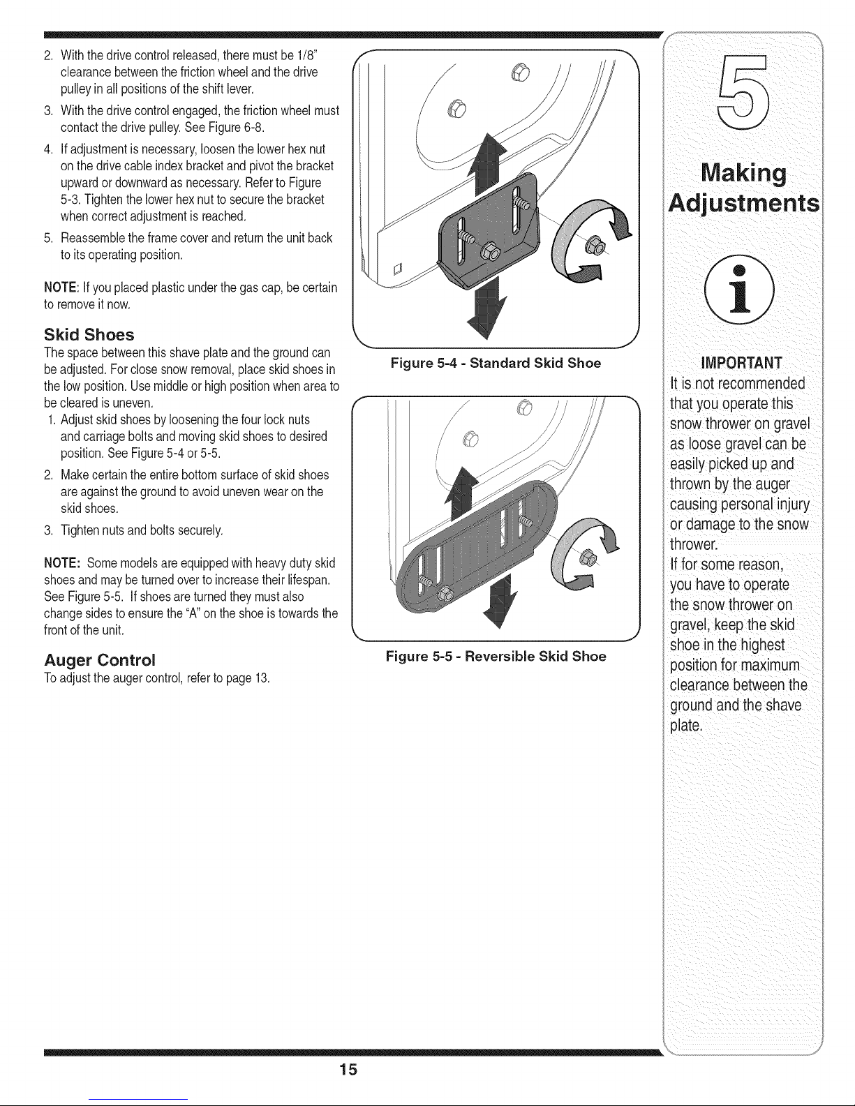
Skid Shoes
Thespacebetweenthisshaveplateandthegroundcan
be adjusted.Forclosesnowremoval,placeskidshoesin
thelowposition.Usemiddleorhighpositionwhenareato
be clearedis uneven.
1.Adjustskidshoesby looseningthefourlocknuts
andcarriageboltsand movingskidshoesto desired
position.SeeFigure5-4 or5-5.
2. Makecertainthe entirebottomsurfaceofskidshoes
areagainstthegroundto avoidunevenwearon the
skidshoes.
3. Tightennutsandboltssecurely.
NOTE: Somemodelsareequippedwith heavydutyskid
shoesandmaybeturnedoverto increasetheirlifespan.
See Figure5-5. If shoesareturnedtheymustalso
changesidesto ensurethe "A"onthe shoeis towardsthe
frontofthe unit.
Auger Control
Toadjustthe augercontrol,referto page13.
Figure 5-4 - Standard Skid Shoe
Figure 5-5 - Reversible Skid Shoe
Mak ng
i
AdjuStments
IMPORTANT
It is not recommended
that you operatethis
snowthrower on gravel
as loose gravelcan be
easilypicked up and
thrownby the auger
causingpersonal injury
ordamageto thesnow
thrower,
Iffor some reason.
you haveto operate
the snowthroweron
gravel,keepthe skid
shoe inthe highest
positionfor maximum
clearance betweenthe
groundand the shave
plate.
15
Page 16
Maintainin,
Engine
Refertothe separateenginemanualpackedwithyour
unitfor all enginemaintenance.
Lubrication
Engine
Refertothe separateenginemanualpackedwithyour
unitfor all enginelubricationinstructions.
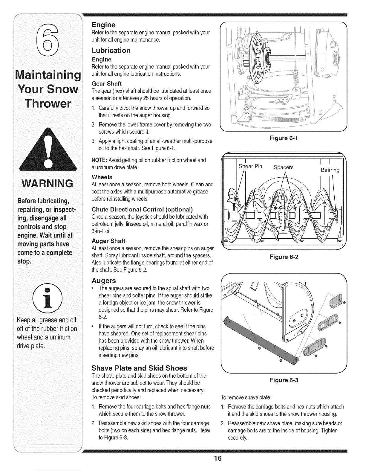
Gear Shaft
Thegear(hex) shaftshouldbelubricatedatleastonce
a seasonor afterevery25 hoursof operation.
1. Carefullypivotthesnowthrowerupand forwardso
thatit restson theaugerhousing.
2. Removethelowerframecoverbyremovingthetwo
screwswhichsecureit.
3.
Applya lightcoatingofan all-weathermulti-purpose
oilto thehexshaft.SeeFigure6-1.
NOTE:Avoidgettingoil on rubberfrictionwheeland
aluminumdriveplate.
Wheels
Atleastonce a season,removeboth wheels.Cleanand
coattheaxleswitha multipurposeautomotivegrease
beforereinstallingwheels.
=,
Figure 6-1
Keepall greaseandoil
Offof therubber friction
wheeland aluminum
drive ,
i
Chute Directional Control (optional)
Oncea season,thejoystickshouldbelubricatedwith
petroleumjelly,linseedoil, mineraloil,paraffinwaxor
3-in-1oil.
Auger Shaft
Atleastonce a season,removethe shearpinson auger
shaft.Spraylubricantinsideshaft,aroundthe spacers.
Alsolubricatethe flangebearingsfoundat eitherendof
theshaft.SeeFigure6-2.
Augers
• Theaugersaresecuredtothespiralshaftwithtwo
shearpinsandcotterpins.If the augershouldstrike
a foreignobjector icejam,thesnowthroweris
designedsothatthepinsmayshear.RefertoFigure
6-2.
If theaugerswillnotturn,checkto seeif thepins
havesheared.Onesetof replacementshearpins
hasbeenprovidedwiththesnowthrower.When
replacingpins,sprayanoil lubricantintoshaftbefore
insertingnewpins.
Shave Plate and Skid Shoes
Theshaveplateand skidshoesonthebottomofthe
snowthroweraresubjectto wear.Theyshouldbe
checkedperiodicallyandreplacedwhennecessary.
Toremoveskidshoes:
.
Removethefourcarriageboltsandhexflangenuts
whichsecurethemtothe snowthrower.
2.
Reassemblenewskidshoeswiththe fourcarriage
bolts(twooneachside)andhexflange nuts.Refer
toFigure6-3.
Figure 6=2
J
Figure 6=3
Toremoveshaveplate:
1. Removethecarriageboltsand hexnutswhichattach
itandthe skidshoesto the snowthrowerhousing.
2. Reassemblenewshaveplate,makingsureheadsof
carriageboltsareto theinsideof housing.Tighten
securely.
16
Page 17
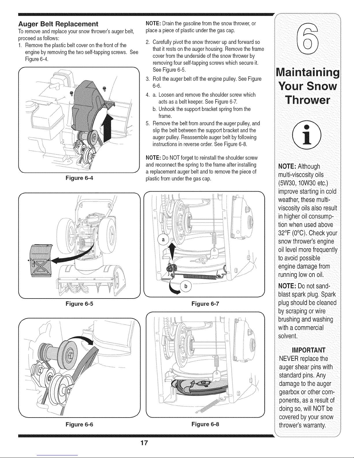
Auger Belt Replacement
Toremoveandreplaceyoursnowthrower'saugerbelt,
proceedasfollows:
1. Removetheplasticbeltcoveronthe frontofthe
enginebyremovingthe two self-tappingscrews. See
Figure6-4.
/
Figure 6-4
i
NOTE:Drainthegasolinefromthesnowthrower,or
placea pieceofplasticunderthegas cap.
.
Carefullypivotthesnowthrowerup andforwardso
thatit restson theaugerhousing.Removetheframe
coverfromtheundersideofthe snowthrowerby
removingfourself-tappingscrewswhichsecureit.
SeeFigure6-5.
.
Rollthe augerbeltoff the enginepulley.SeeFigure
6-6.
4.
a. Loosenand removetheshoulderscrewwhich
actsas a beltkeeper.SeeFigure6-7.
b. Unhookthesupportbracketspringfromthe
frame.
.
Removethe beltfromaroundtheaugerpulley,and
slipthe beltbetweenthe supportbracketandthe
augerpulley.Reassembleaugerbeltby following
instructionsin reverseorder.SeeFigure6-8.
NOTE:Do NOTforgettoreinstallthe shoulderscrew
andreconnectthespringtotheframeafterinstalling
a replacementaugerbeltandto removethepieceof
plasticfromunderthe gascap.
i _ ii i
Maintaining
You rSnow
Th rower
NOTE: Although
multi-viscosityoils
(5W30, 10W30etc.)
improvestarting incold
weather,these multi-
viscosity oils also result
in higher oil consump-
tion when usedabove
32°F (O°C).Check your
snowthrower's engine
oil levelmorefrequently
to avoidpossible
enginedamagefrom
runninglow onoil.
Figure 6-5
\
Figure 6-6
17
Figure 6-7
Figure 6-8
NOTE: Do notsand-
blastspark plug. Spark
plugshould be cleaned
by scraping or wire
brushingand washing
with a commercial
solvent.
IMPORTANT
NEVERreplacethe
auger shear pins with
standardpins.Any
damageto the auger
gearboxor othercom-
ponents as a resultof
(Jongso,wil NOTbe
J
covered byyoursnow
thrower'swarranty.
Page 18
NEVER replacethe
auger shear pinswith
standardhex pins.
Anydamage to the
auger gearboxor
other components
as a resultd failing
to do sowill NOT be
coveredby your snow
thrower'swarranty.
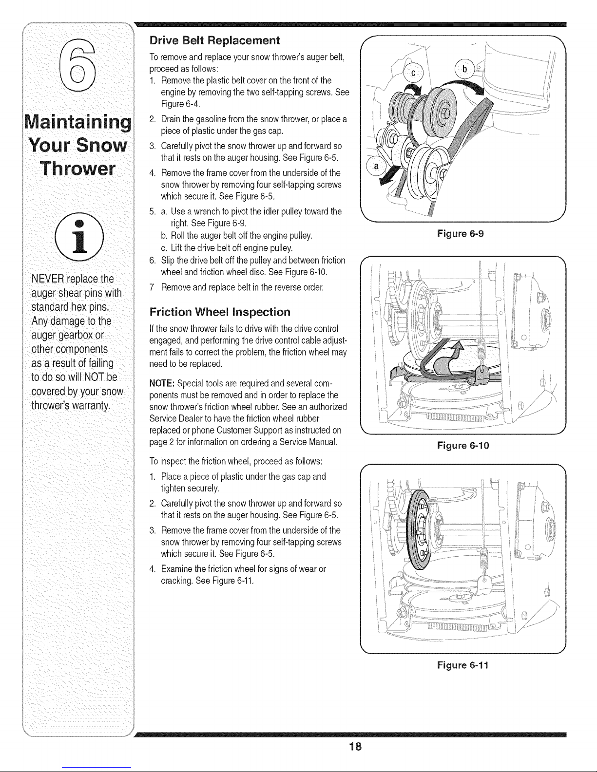
Drive Belt Replacement
Toremoveandreplaceyoursnowthrower'saugerbelt,
proceedasfollows:
1. Removetheplasticbeltcoveron thefrontofthe
enginebyremovingthetwoself-tappingscrews.See
Figure6-4.
2. Drainthegasolinefromthe snowthrower,or placea
pieceof plasticunderthe gascap.
3. Carefullypivotthesnowthrowerupand forwardso
thatit restson theaugerhousing.SeeFigure6-5.
4. Removetheframecoverfromthe undersideofthe
snowthrowerbyremovingfourself-tappingscrews
whichsecureit.See Figure6-5.
5. a. Useawrenchtopivottheidlerpulleytowardthe
right.SeeFigure6-9.
b. Rolltheaugerbeltoff theenginepulley.
c. Liftthedrivebeltoffenginepulley.
6. Slipthe drivebeltoff thepulleyandbetweenfriction
wheelandfrictionwheeldisc.SeeFigure6-10.
7 Removeandreplacebeltinthe reverseorder.
Friction Wheel Inspection
If thesnowthrowerfailsto drivewiththedrivecontrol
engaged,andperformingthedrivecontrolcableadjust-
mentfailstocorrecttheproblem,thefrictionwheelmay
needtobereplaced.
NOTE:Specialtoolsarerequiredand severalcom-
ponentsmustberemovedandinorderto replacethe
snowthrower'sfrictionwheelrubber.Seeanauthorized
ServiceDealerto havethefrictionwheel rubber
replacedorphoneCustomerSupportasinstructedon
page2 forinformationon orderinga ServiceManual.
Toinspectthefrictionwheel,proceedasfollows:
1. Placea pieceof plasticunderthe gascapand
tightensecurely.
2. Carefullypivotthesnowthrowerupand forwardso
thatit restson theaugerhousing.SeeFigure6-5.
3. Removetheframecoverfromthe undersideofthe
snowthrowerbyremovingfourself-tappingscrews
whichsecureit.See Figure6-5.
4. Examinethefrictionwheelforsignsof wearor
cracking.See Figure6-11.
Figure 6=9
Figure 6=10
Figure 6=11
18
Page 19

Observethefollowing,whenpreparingyoursnowthrower
foroff-seasonstorage:
* Drainfuelintoanapprovedcontaineroutdoors,away
fromanyopenflame.Allowengineto cool.Extinguish
cigarettes,cigars,pipesandothersourcesofignition
priortodrainingfuel.Fuelleft inengineduringwarm
weatherdeterioratesand willcauseseriousstarting
problems.
* Ifunitistobestoredover30days,prepareforstorage
asinstructedinthe separateenginemanualpacked
withyourunit.
* Runengineuntilfueltankisemptyandenginestops
dueto lackof fuel.
* Removegasolinefromcarburetorandfueltankto
preventgumdepositsfromformingonthesepartsand
causingpossiblemalfunctionofengine.
* Draincarburetorbypressingupwardonbowldrain,
locatedbelowthe carburetorcover.
* Fuelstabilizers,suchas STA-BIL®,are anacceptable
alternativeinminimizingtheformationoffuel gum
depositsduringstorage.Donotdraincarburetorif
usinga fuel stabilizer.
* Wipeequipmentwithan oiledragto preventrust.
* Removesparkplugandpouroneounceofengineoil
throughsparkplugholeintocylinder.Coversparkplug
holewith rag.Crankengineseveraltimestodistribute
oil. Replacesparkplug.
* Followthelubricationrecommendationsfoundinthe
MaintenanceSection.
* Alwaysstorethe snowthrowerin aclean,dryarea.
WARNING
Never store snow
thrower with fuel
in tank indoorsor
in poorly ventilated
areas, where fuel
fumes may reach an
open flame, spark
or pilot light as on a
furnace, water heater,
clothes dryer or gas
appliance.
Drain fuel intoan
approved container
outdoors, away from
any open flame. Be
certain engine is
cool. Donot smoke.
Fuel left in engine
during warm weather
deteriorates and wiii
cause serious
starting problems.
Do not drain
carburetor if
usingfuel stabilizer.
Never use engine or
carburetor cleaning
products in the fuel
tank or permanent
damage mayoccur.
19
Page 20
I
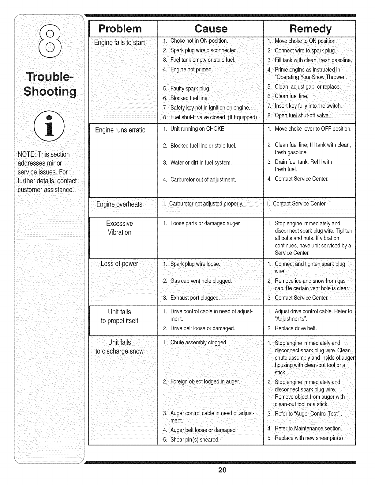
Problem Cause Remedy
Enr,inefails to start - 1. ChokenotinONposition. 1 MovechoketoONpost on
3. Fueltankemptyorstalefuel. 3. Filltankwithclean freshgasoline.
2. Sparkplugwiredisconnected, 2. Connectwireto sparkplug.
4. Enginenot primed. 4. Primeengineasinstructedin
Ible-
_,.w, L,__hOo_lr_n 5 Clean,adjustgap,orreplace
Engineruns erratic 1. UnitrunningonCHOKE. 1. MovechokelevertoOFFposition.
NOTE:This section freshgasoline.
addressesminor 3. Waterordirt infuelsystem. 3. Drainfueltank.Refillwith
service issues. For freshfuel.
further details,contact 4. Carburetoroutofadjustment. 4. ContactServiceCenter.
customerassistance.
5. Fauty sparkpug. • •
6. Blockedfuelline, 6, Cleanfuelline.
7. Safetykeynotin ignitionon engine. 7. Insertkeyfully intotheswitch.
I 8. Fuelshut-ffvalveclosed,(If Equipped) 8. Openfuelshut-offvalve.
2. Blockedfuellineor stalefuel. 2. Cleanfuelline;fill tankwithclean,
OperatingYourSnowThrower.
Engineoverheats 1. Carburetornotadjustedproperly. 1. ContactServtceCenter.
Excessive 1. Loosepartsordamagedauger. 1. Stopengineimmediatelyand
Vibration disconnectsparkplugwire.Tighten
all boltsandnuts.Ifvibration
continues,haveunitservicedbya
ServiceCenter.
Lossof power 1. Sparkplugwireloose. 1. Connectandtightensparkplug
wire.
2. Gascapventholepugged. 2. Removeiceandsnowfromgas
cap.Be certainventholeisclear.
. 3. Exhaustportplugged. 3. ContactServiceCenter.
Unit fails
to propelitself
1. Drivecontrolcable in needofadjust-
ment.
2. Drivebeltlooseor damaged.
1. Adjustdrivecontrolcable.Referto
"Adjustments".
2. Replacedrivebelt.
1. Stopengineimmediatelyand
disconnectsparkplugwire.Clean
chuteassemblyandinsideof auger
housingwith clean-outtoolora
stick.
2. Stopengineimmediatelyand
disconnectsparkplugwire.
Removeobjectfromaugerw th
5. Shearpin(s) sheared.
clean-outtoolora stick,
3. Referto AugerControlTest .
4. Referto Maintenancesection.
5. Replacewith newshearpin(s).
20
Page 21
MANUFACTURER'S LIMITED WARRANTY
Thelimitedwarrantysetforthbelowis givenby MTDLLCwithrespect
tonewmerchandisepurchasedandusedin theUnitedStatesand/orits
territoriesandpossessions,andby MTDProductsLimitedwithrespectto
newmerchandisepurchasedandusedin Canadaand/oritsterritoriesand
possessions(eitherentityrespectively,"MTD").
MTDwarrantsthisproduct(excludingits normalwearpartsasdescribed
below)againstdefectsinmaterialandworkmanshipfor a periodoftwo
(2) yearscommencingon thedate oforiginalpurchaseandwill,at its
option,repairor replace,freeof charge,anypartfoundto be defective
in materialsor workmanship.Thislimitedwarrantyshallonlyapplyif
thisproducthasbeenoperatedand maintainedin accordancewiththe
Operator'sManualfurnishedwiththeproduct,andhasnotbeensubjectto
misuse,abuse,commercialuse,neglect,accident,impropermaintenance,
alteration,vandalism,theft,fire,water,or damagebecauseof otherperilor
naturaldisaster.Damageresultingfromthe installationor use ofanypart,
accessoryorattachmentnotapprovedbyMTDforusewiththeproduct(s)
coveredbythismanualwillvoid yourwarrantyasto anyresultingdamage.
Normalwearpartsarewarrantedto befreefromdefectsinmaterialand
workmanshipfora periodof thirty(30)daysfromthedateof purchase.
Normalwearpartsinclude,butare notlimitedto itemssuchas: batteries,
belts,blades,bladeadapters,grassbags,riderdeckwheels,seats,snow
throwerskidshoes,frictionwheels,shaveplates,augerspiralrubberand
tires.
HOWTOOBTAINSERVICE:Warrantyserviceis available,WITH
PROOFOFPURCHASE,throughyourlocalauthorizedservicedealer.To
locatethedealerin yourarea;
Inthe U.S.A.:
CheckyourYellowPages,or contactMTD LLCat EO.Box361131,
Cleveland,Ohio44136-0019,orcall1-800-800-7310or 1-330-220-4683
or logontoourWeb siteat www.mtdproducts.com.
In Canada:
ContactMTDProductsLimited,Kitchener,ONN2G4J1,or call1-800-
668-1238or logon toourWebsiteatwww.mtdcanada.com.
Thislimitedwarrantydoesnotprovidecoveragein thefollowingcases:
a. Theengineor componentpartsthereof.Theseitemsmaycarrya
separatemanufacturer'swarranty.Refertoapplicablemanufacturer's
warrantyfortermsandconditions.
b. Logsplitterpumps,valves,andcylindershavea separateone-year
warranty.
c. Routinemaintenanceitemssuchaslubricants,filters,blade
sharpening,tune-ups,brakeadjustments,clutchadjustments,deck
adjustments,andnormaldeteriorationof theexteriorfinishdueto use
orexposure.
d. Servicecompletedbysomeoneotherthananauthorizedservice
dealer.
e. MTDdoesnotextendanywarrantyforproductssoldor exported
outsideofthe UnitedStatesand/orCanada,andtheirrespectivepos-
sessionsandterritories,exceptthosesoldthroughMTD'sauthorized
channelsofexportdistribution.
f. Replacementpartsthatarenot genuineMTDparts.
g. Transportationchargesandservicecalls.
h. If Productsare usedcommercially.(MTDmayseparatelyoffer Limited
CommercialWarrantiesoncertainselectproducts.Askyourdealeror
retailerfordetailsorcontactMTDServicefor moreinformation.)
No implied warranty, including anyimplied warranty of merchant-
ability of fitness for a particular purpose, applies after the applicable
period of express written warranty aboveas to the parts as identi-
fied. Noother expresswarranty,whetherwritten or oral, exceptas
mentioned above,given by anyperson or entity, including a dealer
or retailer, with respect to any product, shall bind MTD.Duringthe
period of the warranty, the exclusiveremedyis repair or replacement
of the product as set forth above.
Theprovisionsas setforth in thiswarrantyprovidethe soleand
exclusiveremedyarisingfrom thesale.MTDshallnot be liable
for incidentalorconsequentiallossor damageincluding,without
limitation,expensesincurredfor substituteorreplacementlawncare
servicesor for rentalexpensestotemporarilyreplacea warranted
product.
Somejurisdictionsdonotallowthe exclusionorlimitationof incidentalor
consequentialdamages,or limitationson howlonganimpliedwarranty
lasts,sothe aboveexclusionsor limitationsmaynotapplyto you.
Innoeventshall recoveryof anykind begreaterthantheamountof the
purchasepriceof theproductsold.Alteration of safety features of the
product shallvoid this warranty. Youassumetheriskandliabilityfor
loss,damage,orinjurytoyouandyourpropertyand/ortoothersandtheir
propertyarisingout ofthe misuseorinabilityto usetheproduct.
Thislimitedwarrantyshallnotextendto anyoneotherthanthe original
purchaseror tothe personforwhomitwaspurchasedasa gift.
HOWLOCALLAWSRELATETOTHIS WARRANTY:Thislimitedwar-
rantygivesyouspecificlegalrights,andyoumayalso haveotherrights
thatvary indifferentjurisdictions.
IMPORTANT:OwnermustpresentOriginalProofof Purchasetoobtain
warrantycoverage.
MTD LLC, P.O.BOX 361131CLEVELAND,OHIO 44136-0019; Phone: 1-800-800-7310
MTD Products Ltd., P.O. BOX1386, KITCHENER, ON N2G 4J1; Phone: 1-800-668-1238
21
Page 22

__Tk
/
/
22
Page 23

REF
NO.
N ° DE
REF
18B
42A
42B
42C
42D
42E
42G
42H
43A
43B
18A
42F
PART
NO.
N ° DE
PIECE
1
7t0-t652
2
73t-04792A
73t-05353
3
732-0705
4
71t-t268B
5
746-04229
6
732-04345
7
790-00207A
8
684-04156A
9
750-04474
10
7t4-0t26
11
710-0602
12
7t7-042t0
13
712-04063
14
741-0245
15
790-00206A
16
756-0625
t7
738-0924A
6t8-04288
6t8-04287
19
726-04012
20
750-04477
2t
748-0234
22
732-04311
23
73t-05297
24
7t6-0t04
25
736-0t88
26
736-0626
27
741-04076
28
738-04180
29
73t-04873
30
710-0654A
3t
710-0788
32
790-00185
33
34
736-0242
35
7t0-0627
36
684-04154
37
790-00096
38
748-0t90
39
738-04184A
40
790-00316
41
656-04025A
42
618-04283A
7tt-04416A
618-04284
7t7-t209A
736-0502
736-0336
7t7-t2t0A
6t8-04285
7t6-0t94
43
684-04159
735-04054
790-00174
44
7t6-0t36
45
726-022t
46
790-00t83B
47
756-04109
48
736-0505
49
7t0-t245B
50
736-0tt9
51
790-00230
52
741-09t9
53
750-04571
54
732-04308A
55
7t0-0672
56
756-04252
57
754-0367
58
710-0809
59
790-00208A
60
748-041t2A
6t
732-0264
62
7t2-0413
63
750-04303
64
756-04113
65
736-0247
66
7t0-0t9t
67
748-04053A
68
746-0956A
69
790-00186
70
750-0767
7t
712-04065
72
754-04050
73
710-075t
74
790-002t7A
75
790-002t8A
76
712-04064
77
7t0-0896
78
736-0t73
79
736-0320
80
735-04100
81
735-04099
82
736-30t5
83
790-00289A
84
746-04230
Hex Wash Hd TT Scr. 1/4-20 x .625
Belt Cover (w/4 Way Chute Control)
Belt Cover (Std.)
Cable Control Wire
Drive Shaft Actuator
Drive Clutch Cable 44.83" Lg.
Extension Spring .50D x t.71 Lg.
Guide Bracket - Drive Cable
Shift Rod Ass'y
Axle Support Tube
#9 HI-Pro Key 3/t6x 3/4 Dia HT
Hex Wash Hd Tapp Scr 5/16-18 x 1.00
Gear, 56T
Flange Lock-Nut 5/t6-18 Gr. F Nylon
Hex. Flange Bearing.751" ID
Guide Bracket - Auger Cable
Cable Guide Roller
Hex Shld.Scr.t/4-28 x .375
Dogg Assembly - LH
Dogg Assembly - RH
Push Nut
Spacer .340 x .750 x .360" Lg.
Shoulder Spacer
Torsion Spring .750 ID x .968" Lg.
Spacer
Retaining Ring
Flat Washer .760 ID x 1.49 OD
Flat Washer .580 x 1.125 x .080
Ball Bearing
Axle
Spacer
Hex Wash HD Tap Scr 3/8-16 x .88
Hex Bolt t/4-20 x t.00
Shaft Retainer - LH
See chart on page 30.
Cupped Washer .345 ID x .88 OD x .060
Hex L-Bolt 5/t6-24 x .75 Gr. 5
Friction Wheel Support Brkt Ass'y
Auger Cable Guide Bracket
Spacer .513 ID x 1.0
Shoulder Screw .373 x. 105:TT 1/4-20
Frame Cover
Friction Wheel Disc Assembly
Drive Shaft Assembly (w/o Friction Wheel Ass'y)
Hex Drive Shaft (500)
Planetary Carrier Ass'y
Gear t 2T
Fiat Washer .58 x t .t 2 x .02
Flat Washer 5/8 ID x 1.00D
Gear 18T
Ring Planetary Gear Ass'y (500)
Retaining Ring 1.56 diam.
Friction Wheel Assembly
Friction Wheel Rubber
Friction Plate
Retainer Ring
Cap Speed Nut 1/4 Rod
Wheel Drive Frame
Auger Pulley
Fiat Washer .34 x t .50 x .150
Hex Bolt 6/16-24 x 0.875
L-Wash 5/161D
Bearing Sleeve
Ball Bearing 20 x 47 x 14:6204:DS
Spacer
Torsion Spring .850 ID x .354" Lg.
Hex HD. Cap Scr. 5/16-24 x 1.25 Lg.
Pulley Half
Belt 3/8 X 34.4" Lg.
Hex Bolt 1/4-20 x 1.25
Wheel Drive Idler Bracket
Shoulder Spacer
Extension Spring 3/80D x 2.50
Jam L-Nut 5/8-18 Gr. 5 Nylon
Spacer .875 ID x 1.185 OD
Pulley Half
Fiat Washer .40 ID x 1.25 OD x .160
Hex Screw 3/8-24 x 1.25
Pulley Adapter
Steering Cable
Shaft Retainer - RH
Axle Spacer
Flange Lock-Nut 3/8-16 Gr. F Nylon
Belt .5 x 35.0" Lg.
Hex Bolt t/4-20 x .62 Gr. 5
Pivot Bracket
Shift Bracket
Flange Lock-Nut 1/4-20 Gr. F Nylon
Hex Wash. Hd. TT Scr. t/4-t4 x .625
Flat Washer .28 ID x .74 DE x .063
Flat Washer .38 x 1.38 x .t 25
(Rear left hole)(w/Tec. 318-358 cc engine)
Plug 1/2"
Plug 3/8"
Flat Washer .469 x .875 x .t05
Cover Plate (optional)
Auger Clutch Cable 47.23" Lg.
DESCRiPTiON
DESCRiPTiON
Vis taraudee 1/4_20 x 0,625
Couvre-courroie(avec comm. de la goulotte _ 4 fonctions)
Couvre-courroie (Std.)
Fil de commande de lac&ble
Regulateur
C&ble de t'entrainement 44,83 pc de Ig.
Ressort d'extension 0,5 DE x t,71 pc de Ig.
Support - cgible de I'entrainement
Tige de changement de la vitesses
Tuyau de support de I'essieu
Clavette HI-Pro no. 9 - 3/t6 x 3/4 dia.
Vis autofileteuse & t@e hex et rondelle 5/16-18
Engrenage 56 dents
Contre-ecrou _ embase 5/16-18Qual. F nylon
Roulement & bride & six pans 0,751 DI
Support - C&ble de tari@e
Guide du c&ble
Vis & epaulement t/4-28 x 0,375
CG - cliquet
CD - ctiquet
Ecrou & enfoncer
Entretoise 0,340 x 0,750 x 0,360 pc de Ig.
Entretoise & epaulement
Ressort de torsion 0,750 DI x 0,968 pc de Ig.
Entretoise
Anneau de retenue
Rondelte plate 0,760 DI x 1,49 DE
Rondelle plate 0,580 x 1,125 x 0,080
Roulement & billes
Essieu
Entretoise
Vis autotaraudee 3/8-t6 x 0,88
Vis & t@e hex. t/4-20 x 1,00
Retenue d'arbre CG
Voir tableau de ta page 30.
Rondelle creuse 0,345 DI x 0,88 DE x 0,060
Boulon hex. 5/t6-24 x 0,75 Qual. 5
Support de la roue du friction
Support, guide de la c&ble de latari@e
Entretoise 0,513 DI x 1,0
Vis & epaulement 0,373 x 0,105:1/4-20
Couvercle
Disque de roue du friction
Arbre d'entrainement (sans ensemble de la roue frottement)
Arbre d'entrainement (500)
Porte-roue
Engrenage t2 dents
Rondelle plate 0,58 x t ,12 x 0,02
Rondelle plate 5/8 DIx 1,0 DE
Engrenage 18 dents
Ensemble de I'engrenage (500)
Bague de retenue 1,56 diam.
Ensemble de la roue de frottement
Roue du friction en caoutchouc
Plaque du friction
Bague de retenue
Chapeau & enfoncer
Ch&ssis de I'entratnement de roue
Poulie de la tari@e
Rondelle plate 0,34 x 1,50 x 0,150
Bouton hex. 5/t6-24 x 0,875
Rondelle frein 5/t6 DI
Routement
Roulement & billes 20 x 47 x 14:6204:DS
Entretoise
Ressort de torsion 0,850 DI x 0,354 pc de Ig.
Vis & t_te hexagonal 5/16-24 x 1,25 pc de Ig
Poulie, demi
Courroie trapezoi'dale 3/8 X 34,4 pc de Ig.
Boulon hex. 1/4-20 x 1,25
Support
Entretoise epaul6e
Ressort d'extension 3/8 DE x 2,50
Ecrou de blocage 5/8-t8 Qual. 5 Nylon
Entretoise 0,875 DI x t,185 DE
Moitie poulie
Rondelle plate 0,40 DI x t,25 DE x 0,160
Vis _ t_te hexagonale 3/6-24 x 1,25
Adaptateur de la poulie
C_ble
Retenue d'arbre CD
Entretoise - essieu
Contre-ecrou & embase 3/8-16 Qual. F nylon
Courroie 0,5 x 35,0 pc de Ig.
Boulon hexagonale 1/4-20 x 0,62 Qual. 5
Support de pivot
Support de changement de la vitesses
Contre-ecrou & embase t/4-20 Qual. F nylon
Vis taraudee t/4-14 x 0,625
Rondelle frein 0,28 DI x 0,74 DE x 0,063
Rondelle plate 0,38 x 1,28 x 0,125 (arriere gauche trou)
(avec Tec. 3t8-358 cc moteur)
Bouchon t/2 pc
Bouchon 3/8 pc
Rondelle plate 0,469 x 0,875 x 0,105
Plaque (en option)
C&ble de la tari@e 47,23 pc de Ig.
31A-5003
09.27.07
23
Page 24

9\
22
4
14
9
17
35
53
33 46
11 51
50
41 11 30
/ _32
NOTE:Housing maynot be exactlyas shown.
REMARQUE' L'habitaclepeut_tre legerement
different.
"®_"7
24
Page 25

REF
NO.
N° DE
REF
10
11
12
13
14
15
16
17
18
19
20
21
22
23
24
25
26
27
28
29
30
31
32
33
34
35
38
39
40
41
42
43
44
45
46
47
48
49
5O
51
52
53
54
55
56
57
58
59
60
61
62
63
64
65
1
2
3
4
5
7
8
9
PART
NO.
N° DE
PII_CE
731-2643
684-04057A
710-0347
710-0451
710-0703
712-04063
712-04064
712-04065
725-0157
731-04871
726-04012
731-04705
732-04460
736-0174
731-2635
738-0143
738-0281
720-0284
741-0245
741-0309
756-0981B
790-00075
790-00080A
710-04484
684-04107
684-04108
714-04040
736-0188
738-04124A
741-0493A
790-00087A
790-00138A
790-00181
790-00091
737-3000
731-04870
741-0661A
746-04230
784-5580
719-04291
719-04292
721-0338
741-0662
710-0642
714-0161
715-04021
717-04126
718-04071
721-0325
721-0327
736-0351
736-3084
741-0663
736-0242
721-0328
737-0168
731-05984
710-0451
710-0276
DESCRIPTION
Clean-Out Tool
Impeller Ass'y 12 po
Hex Screw 3/8-16 x 1.75
Carriage Bolt 5/16-18 x .75
Carriage Screw 1/4-20 x .75 Gr. 5
Flange Locknut 5/16-18 Gr. F Nylon
Hex L-Flanged Nut 1/4-20 Gr. F Nylon
Hex L-Flanged Nut 3/8-16 Gr. F Nylon
Cable Tie
Spacer 1.25 x .75 x 3/16" Lg.
Push-on Nut .25 dia.
Chute Adapter
Extension Spring .38 OD x 4.59" Lg.
Wave Washer .660 ID x .88 OD x .010
Cleanout Tool Mount
Shld. Scr..500 Dia. x .335" Lg.
Shoulder Scr .625 Dia x .170
Hand Knob
Hex. Flange Brg..751" I.D.
Self-aligning bearing
Flat Idler Pulley 2.75" OD
Bearing Housing 1.85 ID
Auger Idler Brake Bracket
Hex TT Screw 3/8-16 x .75
See chart on page 30.
Spiral Ass'y LH
Spiral Ass'y RH
Bow Tie Cotter Pin
See chart on page 30.
Flat Washer .760 ID x 1.49 OD
Shear Pin .25 x 1.5 Gr. 2
Flange Bushing
Bushing Housing
Bushing Housing (w/grease fitting hole)
See chart on page 30.
Drift Cutter - Optional
Reversible Slide Shoe (steel)
Grease Fitting (optional)
Spacer 1.25 x .75 x 1.00
Flange Bearing.75 ID x 1.00D x .975
Auger Clutch Cable
Slide Shoe
RH Reduced Auger Housing
LH Reduced Auger Housing
Oil Seal .75 x 1.0 x .125
Flange Bearing .75 ID x 1.00 OD x .50
Thd Forming Scr. 1/4-20 x .75
See chart on page 30.
Hi Pro Key 3/16 x 5/8
Dowel Pin .25 OD x 1.2
Worm Shaft .75 OD
See chart on page 30.
Thrust Collar
Plug, 1/4 x .437
Oil Seal .75x 1 x .131
Flat Washer .76 ID x 1.50D x .03
FI. Washer .510 x 1.120 x .060
Flange Bearing .75 ID x 1.00D x .925
Cupped Washer .345 ID x .88 OD x .060
Loctite Sealant 5699
Grease - AIvania EP Lead Free
Reversible Slide Shoe (plastic)
Carriage Bolt 5/16-18 x .75 (w/steel
slide shoes)
Carriage Bolt 5/16-18 x 1.0 (w/plastic
slide shoes)
DESCRIPTION
Outil de d6gagement de la goulotte
Ventilateur
Visa t_te hex 3/8-16 x 1,75
Boulon ordinaire 5/16-18 x 0,75
Boulon ordinaire 1/4-20 x 0,75 Qual. 5
Contre-6crou a embase 5/16-18 Qual. Fnylon
Contre-6crou a embase 1/4-20 Qual. F nylon
Contre-ecrou a embase 3/8-16 Qual. F nylon
Attache c_ble
Entretoise 1,25 x 0,75 x 3/16 po de Ig.
Ecrou pousser 0,25 diam.
Adaptateur de goulotte d'6jection
Ressort d'extension 0,38 DE x 4,59 po de Ig.
Rondelle ondul6e 0,660 DI x 0,88 DE x 0,010
Montage de la outil de d6gagement de lagoulotte
Visa 6paulement dia. 0,500 pox 0,335 po de Ig.
Vis a epaulement dia 0,625 x 0,170 po
Bouton
Roulement 0,75 DI
Roulement auto-aligneur
Poulie tendeur 2,75 DE
Carter de la roulement 1,85 DI
Support
Vis taraud6e 3/8-16 x 0,75
Voir tableau de la page 30.
Tari@e CG
Tari@e CD
Goupille fendue
Voir tableau de la page 30.
Rondelle plate 0,760 DI x 1,49 DE
Goupille de cisaillement 0,25 x 1,5 po de Ig
Collet a bride
Carter de la collet
Carter de la collet (avec trou pour raccord de graissage)
Voir tableau de la page 30.
Virole de reglage - en option
Patin reversible (acier)
Raccord de graissage (en option)
Entretoise 1,25 x 0,75 x 1,00 po de Ig.
Roulement 0,75 DI x 1,0 DE x 0,975
C_ble de tari@e
Sabot coulissant
Carter de I'engrenage CD
Carter de I'engrenage CG
Joint d'etanch6it6 d'huile 0,75 x 1,0 x 0,125
Roulement 0,75 DI x 1,00 DE x 0,50
Vis taraud6e 1/4-20 x 0,75
Voir tableau de la page 30.
CI6 3/16 x 5/8
Goupille 0,25 x 1,2
Arbre 0,75 DE
Voir tableau de la page 30.
Collet
Bouchon 1/4 x 0,437
Joint d'huile 0,75 DI x 1 x 0,131
Rondelle plate 0,76 DI x 1,5 DE x 0,03
Rondelle frein 0,510 x 1,120 x 0,060
Roulement 0,75 DI x 1,0 DE x 0,925
Rondelle creuse 0,345 DI x 0,88 DE x 0,060
Loctite
Graisseur
Patin reversible (plastique)
Boulon ordinaire 5/16-18 x 0,75 (avec sabot
coulissant acier)
Boulon ordinaire 5/16-18 x 1,0 (avec sabot
coulissant acier)
31A-6002
6.21.07
25
Page 26

StylesH,K,L,P & Q
* With heated grips only/Avec poign6es chauff_es seuJement.
5
15
52
12
43
27
40
_ 24
_11
41
34
Model Number/
Numero de modele
31AE6GKF500
t
Style
18
60
25 *
8
35
18
35
44
26
Page 27
REF PART
NO. NO.
N° DE N° DE
RI_F PII_CE DESCRiPTiON DESCRiPTiON
1 631-04180
1 631-04185
1 631-04183
2 631-04133A
3 631-04134B
4 684-04105B
5 684-04106B
6 710-04326
7 710-04354
8 710-0837
9 710-04586
10 710-1233
11 684-04250
14 712-04064
15 712-04081A
16 714-0104
18 720-0274
19 720-04039
720-04045
20 725-04213
725-1629
21 625-04039
22 725-04216A
23 725-1649
24 725-04393
25 725-1757
26 726-0470
725-0157
27 731-04894C
28 731-04896B
29 732-0193
30 732-04219A
31 732-04238
32 735-0199A
34 736-0267
35 738-04122
36 738-04125
38 746-04396
40 790-00311
41 790-00248A
43 710-0449
44 747-04263
45 720-0201A
46 726-0100
47 735-0234
48 684-04104
49 736-0185
50 631-04181
51 749-04142A
51 749-04191A
52 749-04141A
52 749-04190A
53 720-0284
55 710-04484
56 749-04138A
57 716-04036
59 731-04913
60 738-04126
Handle Panel Ass'y - Yellow
Handle Panel Ass'y - Black
Handle Panel Ass'y-Black w/Chute Control
LH Clutch Lock Handle Ass'y
RH Clutch Lock Handle Ass'y
Engagement Handle Assembly LH
Engagement Handle Assembly RH
Screw #8-16 x .50
Screw 1/4-20 x .375
Oval HD C-Sunk Scr #10 x 5/8
Hex -l-T-Tap Scr 1/4-20 x 1.625
Oval C-Sunk Hd Screw 10-24 x 1.375
Pivot Rod
Hex L-Flanged Nut 1/4-20 Gr. F Nylon
Hex Shoulder Nut 1/4-20
int. Cotter Pin .072 x 1.13" Lg.
Grip
Shift Knob
Shift Knob - Yellow
Lamp #1295 (w/heated grips)
Lamp
Wire Harness
Heated Grip Wire Harness
Socket
Switch
Heated Grip
Cable Tie 19 x 8.39" (w/plug)
Cable Tie (w/heated grips)
Lock Plate
Clutch Lock Cam
Compression Spring .38 iD x .88 Lg
Spring: Clutch Lock
Torsion Spring .8156 x .3038
Rubber Bumper
Flat Washer .38 ID x .87 OD x .09
Shoulder Screw 1/4-20 x 1.345
Shoulder Screw .374 Dia. x 1.05 Lg.
Selector Speed Cable
Shift Lever
Panel Support
Carriage Bolt 5/16-18 x 2.25
Chute Crank Eye Bolt Special
Knob 1.0 x 3.2
Push Nut 3/8" Rod
Grommet
Chute Crank Assembly
Flat Washer .406" i.D. x .75" O.D.
Handle Panel Ass'y - Troy-Bilt
Upper Handle LH
Upper Handle LH (Heated Grips)
Upper Handle RH
Upper Handle RH (Heated Grips)
Handle Knob Assembly
Hex TT Screw 3/8-16 x .75
Lower Handle
E Ring
Steering Control
Pin 3/16
Panneau - jaune
Panneau - noir
Panneau - noir avec comm. de la goulotte
Poignee d'embrayage CG
Poignee d'embrayage CD
Poignee d'entraTnement CG
Poignee d'entraTnement CD
Vis no 8-16 x 0,50
Vis 1/4-20 x 0,375
Vis & t@e goutte de suif no. 10 x 5/8
Vis taraudee 1/4-20 x 1,625
Vis 10-24 x 1,375
Tige de pivot
Contre-ecrou a embase 1/4-20 Qual. F nylon
I_crou 1/4-20
Goupitle fendue int. 0,072 x 1,13 pc de Ig.
Poignee
Bouton
Bouton - jaune
Ampoulte no 1295 (avec poignees chauffees)
Ampoulle
Faisceau de fil
Faisceau de fil - poignee chauffee
Douille
Contracteur
Poignee chauffee
Attache-c&ble 19 x 8,39 pc
Attache-c&bte (avec poignee chauffee)
Palastre de serrure
Came
Ressort de compression 0,38 DIx 0,88 pc de Ig.
Ressort: Verrou d'embrayage
Ressort de torsion 0,8156 x 0,3038
Pare - chocs en caoutchouc
Rondetle plate 0,38 Di x 0,87 DE x 0,09
Visa epaulement 1/4-20 x 1,345
Visa epaulement 0,374 dia. x 1,05 pc de Ig.
C&bte
Levier de changement de la vitesse
Support de panneau de bord
Boulon ordinaire 5/16-18 x 2,25
Bouton & ceil special
Bouton 1,0 x 3,20
#crou pour tige de 3/8 pc
Grummet
Manivelte de la goulotte
Rondelte plate 0,406 DIx 0,75 DE
Panneau - Troy-Bilt
Goutotte superieur CG
Guidon superieur CG (poignee chauffee)
Guidon superieur CD
Guidon superieur CD (poignee chauffee)
Bouton
Vis taraudee 3/8-16 x 0,75
Guidon inferieur
Bague en ,<E,_
Commande d'orientation
Goupille 3/16
31A-6006
6.22.07
27
Page 28

13 /
/15
Manual Chute Control/
Commande de la goulotte
manuelle
/4
/41
/
4 Way Chute Control/
Commande de la
,//' _,
/
/ 24
goulotte & 4 fonctions
55
15
30
/12
../11
28
Page 29
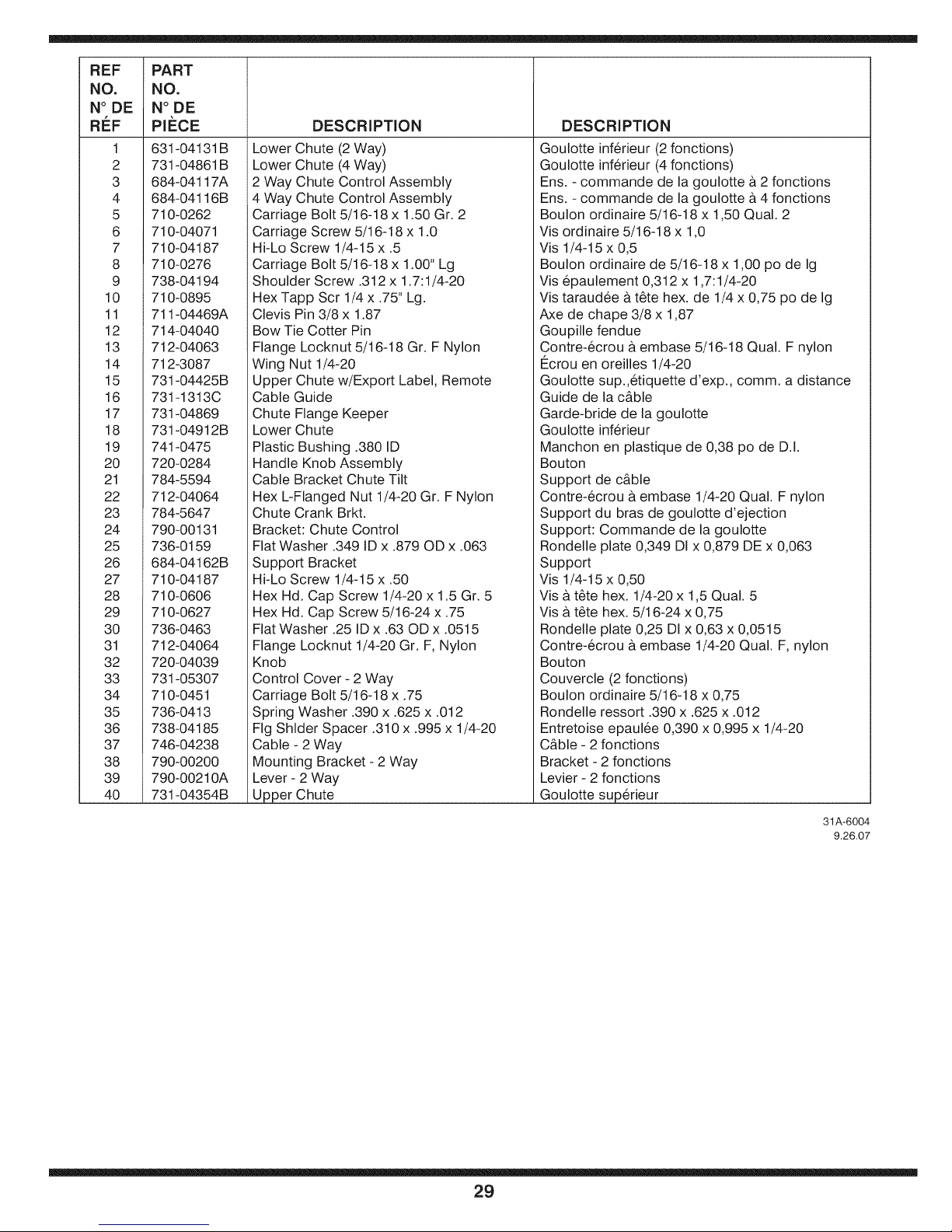
REF
NO.
N° DE
RI_F
1
2
3
4
5
6
7
8
9
10
11
12
13
14
15
16
17
18
19
20
21
22
23
24
25
28
27
28
29
30
31
32
33
34
35
36
37
38
39
4O
PART
NO.
N°DE
PIECE
631-04131B
731-04861 B
684-04117A
684-04116B
710-0262
710-04071
710-04187
710-0276
738-04194
710-0895
711-04469A
714-04040
712-04063
712-3087
731-04425B
731-1313C
731-04869
731-04912B
741-0475
720-0284
784-5594
712-04064
784-5647
790-00131
736-0159
684-04162B
710-04187
710-0608
710-0627
736-0483
712-04064
720-04039
731-05307
710-0451
738-0413
738-04185
746-04238
790-00200
790-00210A
731-04354B
DESCRiPTiON
Lower Chute (2 Way)
Lower Chute (4 Way)
2 Way Chute Control Assembly
4 Way Chute Control Assembly
Carriage Bolt 5/18-18 x 1.50 Gr. 2
Carriage Screw 5/16-18 x 1.0
Hi-Lo Screw 1/4-15 x .5
Carriage Bolt 5/16-18 x 1.00" Lg
Shoulder Screw .312 x 1.7:1/4-20
Hex Tapp Scr 1/4 x .75" Lg.
Clevis Pin 3/8 x 1.87
Bow Tie Cotter Pin
Flange Locknut 5/16-18 Gr. F Nylon
Wing Nut 1/4-20
Upper Chute w/Export Label, Remote
Cable Guide
Chute Flange Keeper
Lower Chute
Plastic Bushing .380 ID
Handle Knob Assembly
Cable Bracket Chute Tilt
Hex L-Flanged Nut 1/4-20 Gr. F Nylon
Chute Crank Brkt.
Bracket: Chute Control
Flat Washer .349 ID x .879 OD x .063
Support Bracket
Hi-Lo Screw 1/4-15 x .50
Hex Hd. Cap Screw 1/4-20 x 1.5 Gr. 5
Hex Hd. Cap Screw 5/18-24 x .75
Flat Washer .25 ID x .63 OD x .0515
Flange Locknut 1/4-20 Gr. F, Nylon
Knob
Control Cover - 2 Way
Carriage Bolt 5/16-18 x .75
Spring Washer .390 x .625 x .012
Fig Shlder Spacer .310 x .995 x 1/4-20
Cable - 2 Way
Mounting Bracket - 2 Way
Lever - 2 Way
Upper Chute
DESCRiPTiON
Goulotte inferieur (2 fonctions)
Goulotte inferieur (4 fonctions)
Ens. - commande de la goulotte & 2 fonctions
Ens. - commande de la goulotte & 4 fonctions
Boulon ordinaire 5/16-18 x 1,50 Qual. 2
Vis ordinaire 5/18-18 x 1,0
Vis 1/4-15 x 0,5
Boulon ordinaire de 5/16-18 x 1,00 po de Ig
Vis epaulement 0,312 x 1,7:1/4-20
Vis taraudee & t_te hex. de 1/4 x 0,75 po de Ig
Axe de chape 3/8 x 1,87
Goupille fendue
Contre-ecrou & embase 5/16-18 Qual. F nylon
I_crou en oreilles 1/4-20
Goulotte sup.,etiquette d'exp., comm. a distance
Guide de la c&ble
Garde-bride de la goulotte
Goulotte inferieur
Manchon en plastique de 0,38 po de D.I.
Bouton
Support de c&ble
Contre-ecrou & embase 1/4-20 Qual. F nylon
Support du bras de goulotte d'ejection
Support: Commande de la goulotte
Rondelle plate 0,349 DI x 0,879 DE x 0,063
Support
Vis 1/4-15 x 0,50
Vis & t&te hex. 1/4-20 x 1,5 Qual. 5
Vis & t_te hex. 5/18-24 x 0,75
Rondelle plate 0,25 DI x 0,63 x 0,0515
Contre-ecrou & embase 1/4-20 Qual. F, nylon
Bouton
Couvercle (2 fonctions)
Boulon ordinaire 5/16-18 x 0,75
Rondelle ressort .390 x .625 x .012
Entretoise epaulee 0,390 x 0,995 x 1/4-20
C&ble - 2 fonctions
Bracket - 2 fonctions
Levier - 2 fonctions
Goulotte superieur
31A-6004
9.26.07
29
Page 30

Assembly
Modele Ensemble de roue Description Roue- Jante Essieu
31AE6GLF590 634-04145 16 x 4.8 x 8 LH X-Trac 734-2038 634-041 73 738-041 68
31AE6GLF596 634-04146 16 x 4.8 x 8 RH X-Trac 734-2038 634-041 73
31AE6GLF597
31AH6KLG
31AH6NKG
31AH51Q4
31AH5MLH
31AH5NQ5
31AE5KLG
31AE6M LG
31AS6ACE
31AE6FFF
31AE6FHF
31AS6LCG
31AE6G KG
31AE6MFH
31AE6M KH
31AE6LHG
31AS6FEE
31AS6FEF
31AE6LHH
31AE5LKH
31AE63KE
31AH6DLE
31AH6DQ3
31AE6GLF501
634-04136
634-04137
634-04141
634-04136
634-04137
634-04144A
634-04141
634-04142A 15 X 5 Snow Hog 734-1 859 634-041 72A
634-04135
634-04135
634-04147A
634-04148A
16 x 6.5 x 8 LH X-Trac
16 x 6.5 x 8 RH X-Trac
16 x4.8 Snow Hog
16 x 6.5 x 8 LH X-Trac
16 x 6.5 x 8 RH X-Trac
13 x4 Snow Hog
16 x4,8 Snow Hog
16 X 6.5 Snow Hog
16 X 6.5 Snow Hog
15 X 5 X 6 LH X-Trac
15 X 5 X 6 RH X-Trac
734-2031
734-2031
734-1530
734-2031
734-2031
734-1732
734-1530
734-1525
734-1525
734-04012
634-041
634-041
634-041
634-041
634-041
634-041
634-041
634-041 74
634-041 74
634-041 72A
634-041 72A
74 738-041 80
74 738-041 80
73 738-04180
74 738-04168
74 738-04168
72A 738-04168
73 738-041 68
738-041 68
738-04168
738-04180
738-041 68
8.21.07
AUGER HOUSING COMPONENTS/COMPOSANTS DU LOGEMENT DES TARIE'RES
I _ I I I
SIZE AUGER HOUSING/ AUGERAXLE/ SHAVE PLATE , GEARBOXASS'Y/ SPACERS/ , WORM GEAR!
TAILLE, LOGEMENTDES , ESSIEUDES LAME, ENSEMBLEDE LA , ENTRETOISE ENGRENAGE
24 684-04065 711-04285 790-00120 618-04171A 731-04870 (1) 717-04449
26 684-04264 711-04284 790-00121 618-04172A 731-04870 (2) 717-04449
28 684-04268 711-04283 790-00118 618-04173A 731-04870 (3) 717-0528A
30 684-04067 711-04282 790-00119 618-04165A 731-04871 (2) 717-0528A
TARIERES TARIERES ' PLATE ' VISSANSFIN ' '
3O
 Loading...