

Page 1
Operator’s Manual
2-Cycle Gas Cultivator
YM121
TABLE OF CONTENTS
Service Information . . . . . . . . . . . . . . . . . . . . . . . . . . . . . . . . . . . . .1
Rules for Safe Operation . . . . . . . . . . . . . . . . . . . . . . . . . . . . . . . . .2
Know Your Unit . . . . . . . . . . . . . . . . . . . . . . . . . . . . . . . . . . . . . . . .4
Assembly Instructions . . . . . . . . . . . . . . . . . . . . . . . . . . . . . . . . . . .4
Oil and Fuel Information . . . . . . . . . . . . . . . . . . . . . . . . . . . . . . . . .4
Starting/Stopping Instructions . . . . . . . . . . . . . . . . . . . . . . . . . . . .4
Operating Instructions . . . . . . . . . . . . . . . . . . . . . . . . . . . . . . . . . . .5
Maintenance & Repair Instructions . . . . . . . . . . . . . . . . . . . . . . . . .5
Cleaning and Storage . . . . . . . . . . . . . . . . . . . . . . . . . . . . . . . . . . .6
Troubleshooting Chart . . . . . . . . . . . . . . . . . . . . . . . . . . . . . . . . . . .6
Specifications . . . . . . . . . . . . . . . . . . . . . . . . . . . . . . . . . . . . . . . . .6
Warranty Information . . . . . . . . . . . . . . . . . . . . . . . . . . . . . . . . . . .E8
All information, illustrations, and specifications in this manual are based
on the latest product information available at the time of printing. We
reserve the right to make changes at any time without notice.
Copyright© 2009 MTD SOUTHWEST INC, All Rights Reserved.
For service call 1-800-800-7310, or 1-800-668-1238 in Canada to
obtain a list of authorized service dealers near you. For more details
about your unit, visit our website at www.mtdproducts.com/
www.mtdproducts.ca.
If you have difficulty assembling this product or have any questions
regarding the controls, operation or maintenance of this unit, please
call the Customer Support Department.
DO NOT RETURN THE UNIT TO THE RETAILER. PROOF OF
PURCHASE WILL BE REQUIRED FOR WARRANTY SERVICE.
THIS PRODUCT IS COVERED BY ONE OR MORE U.S. PATENTS.
OTHER PATENTS PENDING.
Service on this unit both within and after the warranty period should be
performed only by an authorized and approved service dealer.
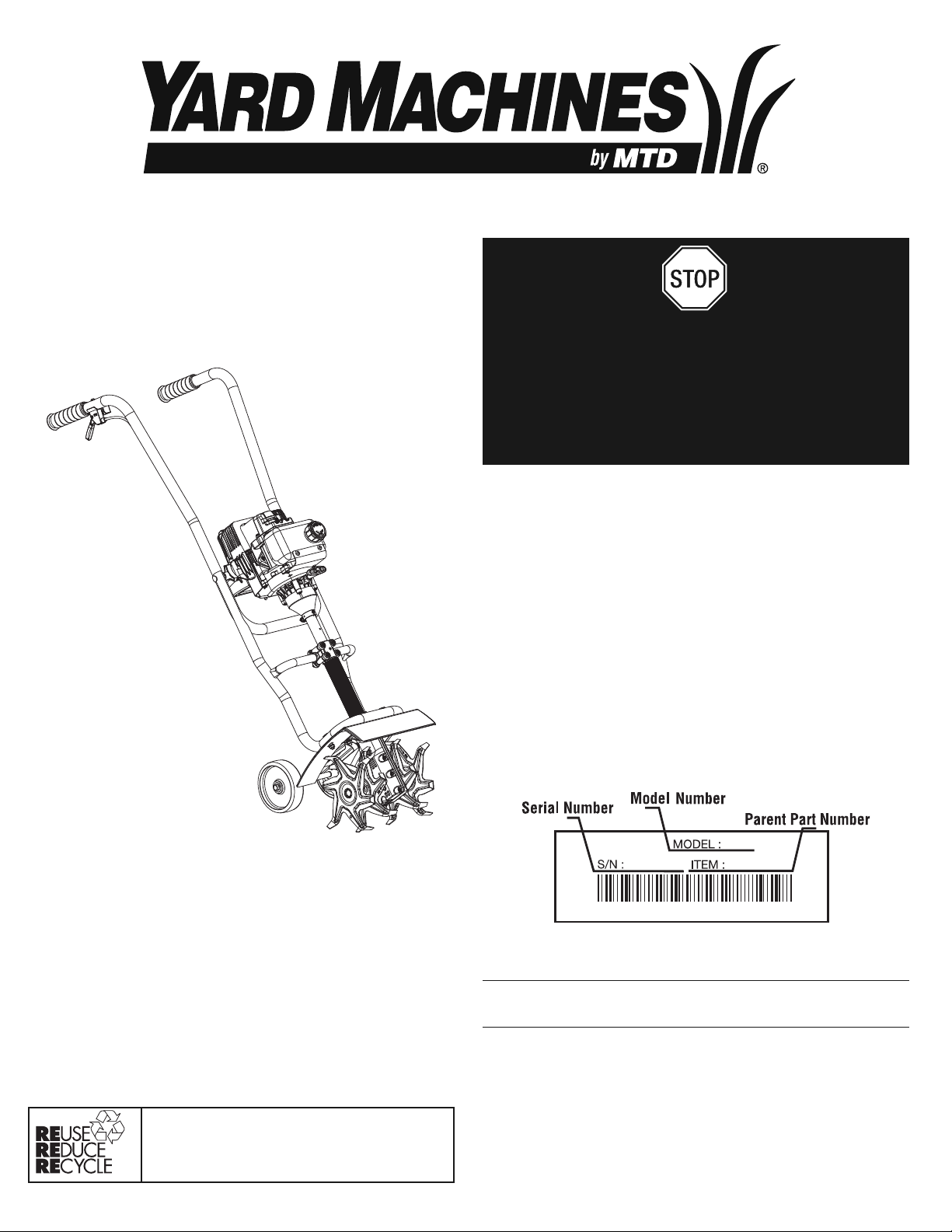
Before beginning, locate the unit’s model plate. It lists the model and
serial numbers of your unit. Refer to the sample plate below and copy
the information for future reference.
Copy the serial number here:
Copy the model and parent part number here:
PART NO. 769-04260 P00 (4/09)
In an effort to reduce the impact on the forests,
and reduce carbon and greenhouse gas
emissions, MTD is using less paper by reducing
the text size of this manual.
DO NOT RETURN
THIS PRODUCT
For Assistance please call 1-800-800-7310 (U.S.) or
1-800-668-1238 (Canada) or visit www.mtdproducts.com/
www.mtdproducts.ca
SAVE THESE INSTRUCTIONS
Page 2

2
RULES FOR SAFE OPERATION
READ ALL INSTRUCTIONS BEFORE OPERATING
• Read the instructions carefully. Be familiar with the controls and proper
use of the unit.
• Do not operate this unit when tired, ill, or under the influence of alcohol,
drugs, or medication.
• Children and teens under the age of 15 must not use the unit, except
for teens guided by an adult.
• All guards and safety attachments must be installed properly before
operating the unit.
• Inspect the unit before use. Replace damaged parts. Check for fuel
leaks. Make sure all fasteners are in place and secure. Replace parts
that are cracked, chipped, or damaged in any way. Do not operate the
unit with loose or damaged parts.
• Carefully inspect the area before starting the unit. Remove all debris
and hard or sharp objects such as glass, wire, etc.
• Be aware of the risk of injury to the head, hands and feet.
• Clear the area of children, bystanders, and pets. At a minimum, keep
all children, bystanders, and pets outside a 50 feet (15 m.) radius; there
still may be a risk to bystanders from thrown objects. Bystanders
should be encouraged to wear eye protection. If you are approached,
stop the unit immediately.
• Squeeze the throttle control and check that it returns automatically to
the idle position. Make all adjustments or repairs before using unit.
SAFETY WARNINGS FOR GAS UNITS
• Store fuel only in containers specifically designed and approved for the
storage of such materials.
• Avoid creating a source of ignition for spilled fuel. Do not start the
engine until fuel vapors dissipate.
• Always stop the engine and allow it to cool before filling the fuel tank.
Never remove the cap of the fuel tank, or add fuel, when the engine is
hot. Never operate the unit without the fuel cap securely in place.
Loosen the fuel tank cap slowly to relieve any pressure in the tank.
• Mix and add fuel in a clean, well-ventilated outdoor area where there
are no sparks or flames. Slowly remove the fuel cap only after stopping
engine. Do not smoke while fueling or mixing fuel. Wipe up any spilled
fuel from the unit immediately. Always wipe unit dry before using.
• Move the unit at least 30 feet (9.1 m) from the fueling source and site
before starting the engine. Do not smoke or allow sparks and open
flames near the area while adding fuel or operating the unit.
WHILE OPERATING
• Never start or run the unit inside a closed room or building. Breathing
exhaust fumes can kill. Operate this unit only in a well ventilated
outdoor area.
• Wear safety glasses or goggles that are marked as meeting ANSI
Z87.1-1989 standards. Also wear ear/hearing protection when
operating this unit. Wear a face or dust mask if the operation is dusty.
Long sleeve shirts are recommended.
• Wear heavy, long pants, boots and gloves. Do not wear loose clothing,
jewelry, short pants, sandals or go barefoot. Secure hair above
shoulder level.
• This unit has a clutch. The tines remains stationary when the engine is
idling. If it does not, have the unit adjusted by an authorized service
technician.
•
Be sure the tines are not in contact with anything before starting the unit.
• Use the unit only in daylight or good artificial light.
• Avoid accidental starting. The operator and unit must be in a stable
position while starting. See Starting/Stopping Instructions.
• Use the right tool. Only use this tool for the purpose intended.
• Use extreme caution when reversing or pulling the unit towards you.
• Do not overreach. Always keep proper footing and balance. Take extra
care when working on steep slopes or inclines.
• Always hold the unit with both hands when operating. Keep a firm grip
on the grips.
• Keep hands, face, and feet at a distance from all moving parts. Do not
touch or try to stop the tines when they are rotating.
• Do not touch the engine or muffler. These parts get extremely hot from
operation. They remain hot for a short time after you turn off the unit.
• Do not operate the engine faster than the speed needed to cultivate.
Do not run the engine at high speed when you are not cultivating.
• Always stop the engine when cultivating is delayed or when walking
from one location to another.
The purpose of safety symbols is to attract your attention to possible
dangers. The safety symbols, and their explanations, deserve your
careful attention and understanding. The safety warnings do not by
themselves eliminate any danger. The instructions or warnings they
give are not substitutes for proper accident prevention measures.
NOTE: Advises you of information or instructions vital to the
operation or maintenance of the equipment.
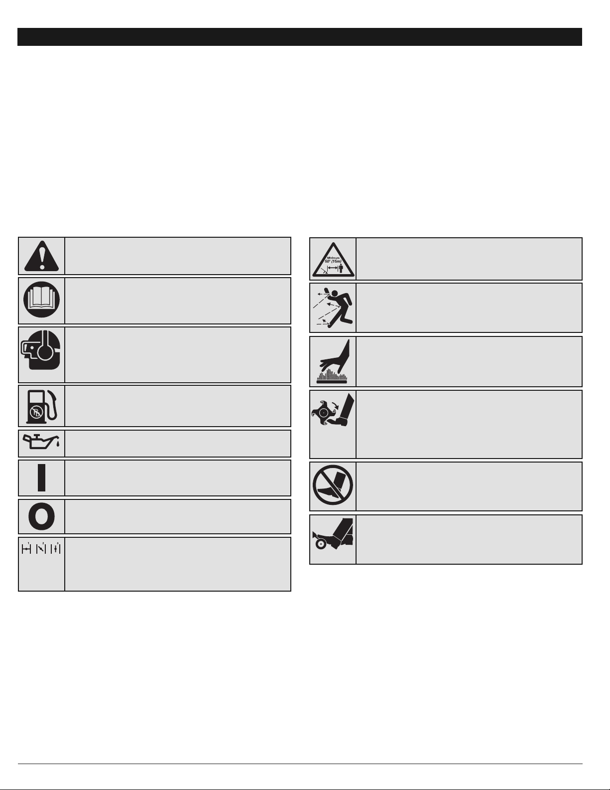
SYMBOL MEANING
• IMPORTANT SAFETY INSTRUCTIONS •
Read the Operator’s Manual and follow all warnings and safety
instructions. Failure to do so can result in serious injury to the operator
and/or bystanders.
FOR QUESTIONS, CALL 1-800-800-7310 IN U.S.
OR 1-800-668-1238 in CANADA
SPARK ARRESTOR NOTE
NOTE: For users on U.S. Forest Land and in the states of California,
Maine, Oregon and Washington. All U.S. Forest Land and the state of
California (Public Resources Codes 4442 and 4443), Oregon and
Washington require, by law that certain internal combustion engines
operated on forest brush and/or grass-covered areas be equipped with a
spark arrestor, maintained in effective working order, or the engine be
constructed, equipped and maintained for the prevention of fire. Check with
your state or local authorities for regulations pertaining to these
requirements. Failure to follow these requirements could subject you to
liability or a fine. This unit is factory equipped with a spark arrestor. If it
requires replacement, ask your LOCAL SERVICE DEALER to install the
Accessory Part #753-04926 Muffler Assembly.
CALIFORNIA PROPOSITION 65 WARNING
WARNING
THE ENGINE EXHAUST FROM THIS PRODUCT CONTAINS
CHEMICALS KNOWN TO THE STATE OF CALIFORNIA TO CAUSE
CANCER, BIRTH DEFECTS OR OTHER REPRODUCTIVE HARM.
WARNING:
Gasoline is highly flammable, and its vapors
can explode if ignited. Take the following precautions:
WARNING:
When using the unit, you must follow the safety
rules. Please read these instructions before operating the unit in
order to ensure the safety of the operator and any bystanders.
Please keep these instructions for later use.
SAFETY ALERT:
Indicates danger, warning or caution.
Attention is required in order to avoid serious personal
injury. May be used in conjunction with other symbols or
pictographs.
DANGER:
Failure to obey a safety warning will result in
serious injury to yourself or to others. Always follow the
safety precautions to reduce the risk of fire, electric shock
and personal injury.
WARNING:
Failure to obey a safety warning can result
in injury to yourself and others. Always follow the safety
precautions to reduce the risk of fire, electric shock and
personal injury.
CAUTION:
Failure to obey a safety warning may result in
property damage or personal injury to yourself or to others.
Always follow the safety precautions to reduce the risk of
fire, electric shock and personal injury.
Page 3
3
RULES FOR SAFE OPERATION
• SAFETY ALERT SYMBOL
Indicates danger, warning or caution. May be used in
conjunction with other symbols or pictographs.
• HOT SURFACE WARNING
Do not touch a hot muffler or cylinder. You may get
burned. These parts get extremely hot from operation.
When turned off they remain hot for a short time.
• WARNING - READ OPERATOR'S MANUAL
Read the operator’s manual(s) and follow all warnings and
safety instructions. Failure to do so can result in serious
injury to the operator and/or bystanders.
• WEAR EYE AND HEARING PROTECTION
WARNING: Thrown objects and loud noise can cause
severe eye injury and hearing loss. Wear eye protection
meeting ANSI Z87.1-1989 standards and ear protection when
operating this unit. Use a full face shield when needed.
• KEEP BYSTANDERS AWAY
WARNING: Keep all bystanders, especially children
and pets, at least 50 feet (15 m.) from the operating area.
• THROWN OBJECTS AND ROTATING CUTTER CAN
CAUSE SEVERE INJURY
WARNING: Small objects can be propelled at high
speed, causing injury. Keep away from the rotating rotor.
SYMBOL MEANING
• CHOKE CONTROL
1. • FULL choke position
2. • PARTIAL choke position
3. • RUN choke position
• UNLEADED FUEL
Always use clean, fresh unleaded fuel
• ON/OFF STOP CONTROL
ON / START / RUN
• ON/OFF STOP CONTROL
OFF or STOP
• If you strike or become entangled with a foreign object, stop the engine
immediately and check for damage. Do not operate before repairing
damage. Do not operate the unit with loose or damaged parts.
• Stop and switch the engine to off for maintenance, repair, or to install or
remove the tines.
•
Use only original equipment manufacturer replacement parts and
accessories for this unit. These are available from your authorized service
dealer. Use of any unauthorized parts or accessories could lead to
serious injury to the user, or damage to the unit, and void your warranty.
• Keep unit clean of vegetation and other materials. They may become
lodged between the tines.
• To reduce fire hazard, replace faulty muffler and spark arrestor, keep
the engine and muffler free from grass, leaves, excessive grease or
carbon build up.
• SAFETY AND INTERNATIONAL SYMBOLS •
This operator's manual describes safety and international symbols and pictographs that may appear on this product. Read the operator's manual
for complete safety, assembly, operating, maintenance, and repair information.
SYMBOL MEANING
OTHER SAFETY WARNINGS
• Never store the unit, with fuel in the tank, inside a building where fumes
may reach an open flame or spark.
• Allow the engine to cool before storing or transporting. Be sure to
secure the unit while transporting.
• Store the unit in a dry area, locked up or up high
to prevent unauthorized use or damage, out of the reach of children.
• Never douse or squirt the unit with water or any other liquid. Keep
handles dry, clean and free from debris. Clean after each use. See the
Cleaning and Storage instructions.
• Keep these instructions. Refer to them often and use them to instruct
other users. If you loan someone this unit, also loan them these
instructions.
SAVE THESE INSTRUCTIONS
• OIL
Refer to operator’s manual for the proper type of oil.
• GARDEN CULTIVATORS – ROTATING TINES CAN
CAUSE SEVERE INJURY
WARNING: Stop the engine/motor and allow the
tines to stop before installing or removing tines, or
before cleaning or performing any maintenance. Keep
hands and feet away from rotating tines.
• NO STEP
Always keep proper footing and balance. Do not
overreach, take extra care when working on steep
slopes or inclines.
• PLACE LEFT FOOT HERE
Avoid accidental starting. Stand in the starting position
whenever pulling the starter rope. The operator and unit
must be in a stable position while starting.
Page 4
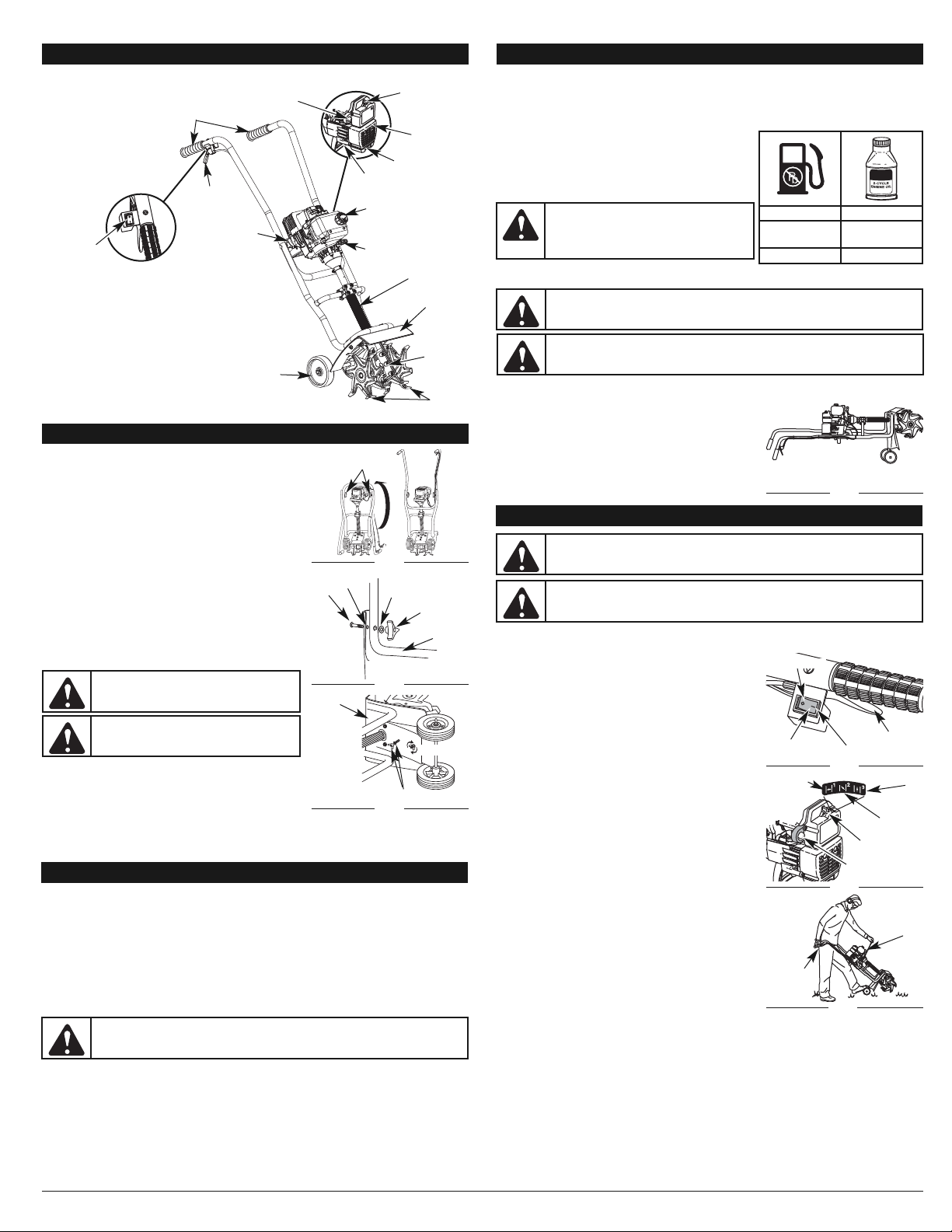
USING FUEL ADDITIVES
The bottle of 2-cycle oil that came with your unit contains a fuel additive which will help inhibit corrosion
and minimize the formation of gum deposits. It is recommended that you use our 2-cycle oil with this unit.
If unavailable, use a good 2-cycle oil designed for air-cooled engines along with a fuel additive, such as
STA-BIL® Gas Stabilizer or an equivalent. Add 0.8 oz. (23 ml.) of fuel additive per gallon of fuel
according to the instructions on the container. NEVER add fuel additives directly to the unit's fuel tank.
Thoroughly mix the proper ratio of 2-cycle engine oil with
unleaded gasoline in a separate fuel can. Use a 40:1 fuel/oil
ratio. Do not mix them directly in the engine fuel tank. See the
table below for specific gas and oil mixing ratios.
NOTE: One gallon (3.8 liters) of unleaded gasoline mixed with
one 3.2 oz. (95 ml.) bottle of 2-cycle oil makes a 40:1
fuel/oil ratio.
NOTE: Dispose of the old fuel/oil mix in accordance to
Federal, State and Local regulations.
FILLING THE FUEL TANK
Make sure the cultivator is in a horizontal position when filling or
adding fuel to the tank. (Fig. 4)
OIL AND FUEL MIXING INSTRUCTIONS
Old and/or improperly mixed fuel are the main reasons for the unit not running properly. Be sure to use
fresh, clean unleaded fuel. Follow the instructions carefully for the proper fuel/oil mixture.
DEFINITION OF BLENDED FUELS
Today's fuels are often a blend of gasoline and oxygenates such as ethanol, methanol, or MTBE (ether).
Alcohol-blended fuel absorbs water. As little as 1% water in the fuel can make fuel and oil separate. It
forms acids when stored. When using alcohol-blended fuel, use fresh fuel (less than 60 days old).
USING BLENDED FUELS
If you choose to use a blended fuel, or its use is unavoidable, follow recommended precautions:
• Always use the fresh fuel mix explained in your operator's manual
• Always agitate the fuel mix before fueling the unit
• Drain the tank and run the engine dry before storing the unit
4
OIL AND FUEL INFORMATION
STARTING/STOPPING INSTRUCTIONS
STARTING INSTRUCTIONS
1. Mix gas with oil. Fill fuel tank with fuel/oil mixture. Refer to Oil and Fuel Mixing Instructions.
2. Fully press and release the primer bulb 10 times, slowly. Some
amount of fuel should be visible in the primer bulb and fuel lines
(Fig. 6).
If fuel is not visible in the bulb, press and release the
bulb until fuel is visible.
3. Place the choke lever in Position 1 (Fig. 6).
4. Stand between the handlebars and support the unit by
placing your left foot on the wheel bracket assembly and
gripping the handlebar grip with your right hand (Fig. 7).
NOTE: Tilt the unit back slightly to bring the tines off the ground
when starting.
5. While squeezing the throttle control, grasp the starter rope grip
with your left hand. Pull the rope briskly 5 times.
NOTE: The throttle control should be kept squeezed throughout
the remainder of these steps.
6. Move the blue choke lever to Position 2. (Fig. 6)
7. While squeezing the throttle control, pull the starter rope 3 to
5 times to start the engine.
8. Keep the throttle squeezed and allow the engine to warm up
for 30 to 60 seconds.
NOTE: Engine may take longer to warm up and reach maximum
operating speed at colder temperatures.
9.
While continuing to squeeze the throttle control, move the
blue choke lever in Position 3 (Fig. 6) and continue warming
the engine for an additional 60 seconds. During this time the
unit may be used.
NOTE: Unit is properly warmed up when engine accelerates
without hesitation.
IF... The engine does not start, go back to step 2.
IF... The engine fails to start after a few attempts, place the
choke lever in Position 3 and squeeze the throttle control.
Pull the starter rope briskly 3 to 8 times. The engine
should start. If not, repeat.
IF WARM... If the engine is already warm, make sure the On/Off
control is in the ON (I) position and start the unit with the
choke lever in Position 2. After the unit starts, move the blue
choke lever to Position 3.
STOPPING INSTRUCTIONS
1. Release your hand from the throttle control. Allow the engine
to cool down by idling.
2. Press and hold the On/Off Control in the STOP (O) position until the engine comes to a complete
stop.
WARNING:
Remove fuel cap slowly to avoid injury from fuel spray. Never operate the
unit without the fuel cap securely in place.
WARNING:
Add fuel in a clean, well ventilated outdoor area. Wipe up any spilled fuel
immediately. Avoid creating a source of ignition for spilt fuel. Do not start the engine until
fuel vapors dissipate.
WARNING:
Remove fuel cap slowly to avoid injury from fuel spray. Never operate the
unit without the fuel cap securely in place.
WARNING:
Avoid accidental starting. Make sure you are in the starting position when
pulling the starter rope (Fig. 7). To avoid serious injury, the operator and unit must be
in a stable position while starting.
Stop/Off (O)
On/Off
Control
Start/On (I)
Fig. 5
Position 1
Position 3
Position 2
Choke
Lever
Fig. 6
Starting Position
Starter
Rope
Throttle
Control
Fig. 7
Primer Bulb
KNOW YOUR UNIT
APPLICATION
• Cultivating sod and light to
medium soil
• Cultivating in garden areas,
around trees, etc.
Choke
Lever
Throttle
Control
Handgrip
Handlebar
Knob
Primer Bulb
Air Filter/
Muffler
Cover
Spark Plug
Gear Box
Starter Rope
Grip
Muffler
On/Off Stop
Control
Wheel Bracket
Assembly
Shaft Tube Grip
Fuel Cap
ASSEMBLING THE UNIT
Before operating, position the unit’s handlebars.
NOTE: You may also need to reposition the wheel height before
using the cultivator. Refer to the Adjusting Tine Depth
section.
Begin by carefully unpacking the contents and making sure that
nothing is damaged.
POSITIONING THE HANDLEBARS
1. Loosen the two knobs on the inside of the handlebars (Fig. 1).
2. With the unit upright, swing the handlebars up into the
operating position (Fig. 1).
NOTE: Take care not to pinch the throttle cable or switch wires
when positioning the handlebar.
3. Tighten the knobs to secure the handlebars in place.
NOTE: Do not over-tighten the knobs.
4. Readjust the throttle cable and switch the wires so they are
smooth and tight against the handlebar assembly. This will
help prevent them from catching or snagging during normal
operation.
INSTALLING THE WHEEL BRACKET ASSEMBLY
If the wheel bracket assembly is not installed, or if you ever need
to remove or reinstall it, follow the ensuing instructions.
1. With the unit on its side, place the wheel bracket assembly
on the underside of the tine guard (Fig. 3).
2. Install a carriage bolt through each of the slotted holes in the
wheel bracket and into the tine guard.
3. On the TOP side of the tine guard, install a lock washer and a
wing nut onto each of the bolts (Fig. 3).
4. Make sure the square shoulder of the bolts is pushed through the slotted holes in the wheel bracket.
Tighten the wing nuts (Fig. 3).
NOTE: Do not over-tighten the wing nuts. Loosen the wing nuts to adjust wheel height.
ASSEMBLY INSTRUCTIONS
Handlebar
Knob
Fig. 1
Bolt
Washer
Hole
Handlebar
Knob
Fig. 2
Tine
Guard
Wing Nut & Lock Washer
Fig. 3
CAUTION:
For proper engine operation and maximum reliability, pay strict attention to
the oil and fuel mixing instructions on the 2-cycle oil container. Using improperly mixed fuel
can severely damage the engine.
WARNING:
Gasoline is extremely flammable.
Ignited vapors may explode. Always stop the engine
and allow it to cool before filling the fuel tank. Do not
smoke while filling the tank. Keep sparks and open
flames at a distance from the area.
Tines
Tine Guard
WARNING:
To avoid injury from the tines,
wear heavy gloves and a long sleeve shirt when
installing the wheel bracket assembly.
WARNING:
To prevent serious personal injury,
the wheel bracket assembly must be installed
when operating the unit.
Tighten
Handlebars
OIL AND FUEL INFORMATION
Fig. 4
Throttle Control
MIXING RATIO - 40:1
UNLEADED GAS 2 CYCLE OIL
1 GALLON
(3.8 LITERS)
3.2 FL. OZ.
(95 ml)
1 LITER 25 ml
Page 5
5
OPERATING INSTRUCTIONS
OPERATING TIPS
1. Move the cultivator to the work area prior to starting the
engine. Transport the cultivator by pushing it on its wheels.
2. Start the unit as described in the Starting Instructions.
3. With the engine running and the tines off the ground,
depress the throttle control to increase the engine speed.
4. Holding both of the handlebar grips firmly, slowly lower the
cultivator until the tines make contact with the ground (Fig. 8).
5. As cultivating action begins, pull back on the cultivator so
that the tines can penetrate the ground.
6. Once the ground has been broken, continue at a moderate pace until you are familiar with the
controls and the handling of the cultivator.
7. Pull the cultivator backwards to improve the depth of cultivation and reduce your effort.
8. If the tines are digging too deep or not deep enough, adjust them according to Adjusting Tine Depth.
WARNING:
Dress properly to reduce the risk of injury when operating this unit. Do not
wear loose clothing or jewelry. Wear eye and ear/hearing protection. Wear heavy long
pants, boots and gloves. Do not wear short pants, sandals or operate barefoot.
MAINTENANCE AND REPAIR INSTRUCTIONS
MAINTENANCE SCHEDULE
Perform these required maintenance procedures at the frequency stated in the table. These procedures
should also be a part of any seasonal tune-up.
NOTE: Some maintenance procedures may require special tools or skills. If you are unsure about
these procedures take your unit to any non-road engine repair establishment, individual or
authorized service dealer.
NOTE: Maintenance, replacement, or repair of the emission control devices and system may be
performed by any non-road engine repair establishment, individual or authorized service dealer.
In order to assure peak performance of your engine, inspection of the engine exhaust port may be necessary
after 50 hours of operation. If you notice lost RPM, poor performance or general lack of acceleration, this
service may be required. If you feel your engine is in need of this inspection, refer service to any non-road
engine repair establishment, individual or authorized service dealer for repair. DO NOT attempt to perform this
process yourself as engine damage may result from contaminants involved in the cleaning process for the port.
WARNING:
To prevent serious injury, never perform maintenance or repairs with unit
running. Always service and repair a cool unit. Disconnect the spark plug wire to ensure that
the unit cannot start.
FREQUENCY MAINTENANCE REQUIRED SEE
Before starting engine Fill fuel tank with fresh fuel mix p. 4
Every 10 hours Clean and re-oil air filter p. 5
Every 25 hours Check and clean spark arrestor
Check spark plug condition and gap
p. 5
p. 6
Every 50 hours Inspect exhaust port and spark arrestor screen for clogging
or obstruction to assure maximum performance levels.
p. 5
6. Replace the air filter inside the muffler cover (Fig. 13).
NOTE: Operating the unit without the air filter and cover
assembly will VOID the warranty.
Reinstalling the Air filter/Muffler Cover
1. Place the air filter/muffler cover over the back of the
carburetor and muffler.
NOTE: The blue choke lever must be in Postion 2 (Fig. 12) to
remove the air filter/ muffler cover.
2. Insert the four (4) screws into the holes in the air filter/ muffler
cover (Fig. 12) and tighten. Use a # T20 Torx bit screwdriver.
Do not over tighten. Do not force.
SPARK ARRESTOR MAINTENANCE
1. Remove air filter/muffler cover. Refer to Removing the Air
Filter/Muffler Cover.
2. Locate the muffler, but do not remove it. Find the screw on
the bottom of the muffler (Fig. 17). Remove the screw using
either a torx #20 or flat blade screwdriver.
3. Carefully pry up the left side spark arrestor hood. Two tabs
act as hinges on the right side of the hood. Flip open the
spark arrestor hood like a door and then pull its tabs out of
the muffler slots.
4. Using a small flat blade screwdriver, carefully pry the spark
arrestor screen out from the inside of the spark arrestor
hood.
5. Clean the spark arrestor screen with a wire brush. Replace it
if it is damaged, or if you are unable to clean it thoroughly.
6. Reinstall the spark arrestor screen snugly back into the spark
arrestor hood.
7. Reinstall the two hood tabs into the two muffler slots and flip
the spark arrestor hood closed.
8. Replace the screw you removed in Step 2 and tighten it
securely.
9. Reinstall the air filter/muffler cover.
CARBURETOR ADJUSTMENTS
The engine’s idle speed adjuster is adjustable through the air
filter/muffler cover (Fig 18).
NOTE: Careless adjustments can seriously damage your unit.
An authorized service dealer should make carburetor
adjustments.
Check Fuel Mixture
Old and/or improperly mixed fuel is usually the reason for the unit
not running properly. Drain and refill the tank with fresh, properly
mixed fuel prior to making any adjustments. Refer to Oil and Fuel
Information.
Clean Air Filter
The condition of the air filter is important to the operation of the unit. A dirty air filter will restrict air flow
and change the air/fuel mixture. This is often mistaken for an out of adjustment carburetor. Check the
condition of the air filter before adjusting the idle speed adjuster. Refer to Air Filter Maintenance.
Adjust Idle Speed Adjuster
If after checking the fuel mixture and cleaning the air filter the
engine still will not idle, adjust the idle speed screw as follows:
1. Start the engine and let it run for about 2-3 minutes at a high
speed (full throttle) to warm up. Refer to the
Starting/Stopping Instructions.
NOTE: Ensure the tines are not in contact with the ground when
adjusting the idle.
2. Release the throttle control and let the engine idle. If the engine stops, insert a small phillips
screwdriver into the hole in the muffler cover (Fig. 18). Turn the idle speed screw clockwise 1/8 of a
turn at a time (as needed) until the engine idles smoothly.
NOTE: The tines should not rotate during engine idle.
3. If the tines rotate when the engine idles, turn the idle speed screw counterclockwise 1/8 of a turn
at a time (as needed), to reduce idle speed.
Checking the fuel mixture, cleaning the air filter, and adjusting the idle speed screw should solve most
engine problems. If not and all the following are true:
• The engine will not idle
• The engine hesitates or stalls on acceleration
• There is a loss of engine power
Have the carburetor adjusted by an authorized service dealer.
WARNING:
If the exhaust deflector assembly
is not tightened securely, it could fall off causing
damage to the unit and possible serious
personal injury.
TINE REMOVAL AND REPLACEMENT
NOTE: All installation instructions are explained from the
operating postion.
All 4 tines should be replaced at the same time because they will
wear evenly through normal use. Work on one side at a time.
1. Press and hold the On/Off Stop Control in the STOP (O)
position and disconnect the spark plug wire.
2. Lay the cultivator back on a flat level surface with the
handles touching the ground so that the cultivator is in a
horizontal postion.
NOTE: It may be necessary to wash any dirt off the tines and
shaft for easier tine removal.
3. Remove the click pin from each end of the tine shaft. Slide
the tines off of the shaft (Fig. 10).
4. Clean and oil the shaft.
5.
Slide on the new tines with the hubs facing in towards each other.
Making sure that the rotation arrows are facing the gearbox when
installing the tines on left tine shaft and away from the gearbox for
the right tine shaft. (Fig. 11)
6. Secure the new tines to the shaft with click pins. (Fig. 10)
AIR FILTER MAINTENANCE
Removing the Air Filter/Muffler Cover
1. Place the blue choke lever in Position 2.
NOTE: The blue choke lever must be in Position 2 (Fig. 12) to
remove the air filter/ muffler cover.
2. Remove the four (4) screws securing the air filter/muffler
cover (Fig. 12). Use a # T20 Torx bit screwdriver.
3. Pull the cover from the engine. Do not force.
Cleaning the Air Filter
Clean and re-oil the air filter every 10 hours of operation. It is an
important item to maintain. Failure to maintain your air filter properly
can result in poor performance or can cause permanent damage to
your engine.
1. Remove the air filter/muffler cover. Refer to the Removing the
Air filter/Muffler Cover section.
2. Remove the air filter from inside the air filter/muffler cover
(Fig. 13).
3. Wash the filter in detergent and water (Fig. 14). Rinse the filter
thoroughly. Squeeze out excess water. Allow it to dry completely.
4. Apply enough SAE 30 oil to lightly coat the filter (Fig. 15).
5. Squeeze the filter to spread and remove extra oil (Fig. 16).
ADJUSTING TINE DEPTH
Tine adjustment will vary depending on the type of soil being cultivated and how it will be used.
Generally, adjusting the tines to break the soil 4 to 6 inches is recommended for most gardens. Adjust
the tines as follows:
1. Stop the engine and disconnect the spark plug wire.
2. Loosen (do not remove) the two wing nuts on the tine guard (Fig. 9).
3. Slide the wheel bracket assembly down for shallower penetration, and up for deeper tine
penetration.
4. Once the tines are in the desired position, tighten the wing nuts, making sure that the carriage bolts
are seated properly through the bracket.
5. If the tine depth is incorrect, repeat steps 2 to 4.
6. Reconnect the spark plug wire and continue use.
TRANSPORTING THE UNIT
1. Stop the engine.
2. Slide the wheel bracket assembly all the way down.
3. Tilt the unit back until the tines clear the ground.
4. Push or pull the unit to the next location.
CAUTION:
To prevent serious personal injury,
never pick-up or carry the unit while the engine is
running.
WARNING:
To prevent serious personal injury,
always wear heavy gloves when handling the
tines.
WARNING:
To prevent serious personal injury,
always stop the engine when operation is
delayed or when transporting the unit from one
location to another
WARNING:
To prevent serious personal injury, use extreme caution when reversing or
pulling the unit towards you.
Fig. 8
Fig. 9
Fig. 14
Fig. 15
Air Filter
Inside Muffler Cover
Fig. 13
Blue Choke
Lever
Screws
Position 2
Fig. 12
Screws
Fig. 16
Slots
Spark
Arrestor
Hood
Screw
Fig. 17
Tab s
Spark Arrestor
Screen
Engine
Muffler
Idle Speed Screw
Fig. 18
WARNING:
To avoid serious personal injury,
always turn your unit off and allow it to cool
before you clean or service it.
WARNING:
The unit will still run during idle
speed adjustments. Wear protective clothing and
observe all safety instructions to prevent serious
personal injury.
Gearbox
Left Tine
Shaft
Fig. 11
Right Tine Shaft
Fig. 10
Click Pin
Tine
Left Tine Shaft
Page 6

CAUSE ACTION
Old or improperly mixed fuel Drain gas tank and add fresh fuel mixture
Dirty air filter Clean or replace the air filter
Plugged spark arrestor Clean or replace spark arrestor
CAUSE ACTION
Old or improperly mixed fuel Drain gas tank and add fresh fuel mixture
Fouled spark plug Replace or clean the spark plug
Plugged spark arrestor Clean or replace spark arrestor
6
TROUBLESHOOTING
CAUSE ACTION
On/Off control in the OFF position Turn On/Off control to ON
Empty fuel tank Fill fuel tank with properly mixed fuel
Primer bulb wasn't pressed enough
Press primer bulb fully and slowly 10 times
Engine is flooded
Place choke lever into position 3, squeeze the
throttle trigger and pull the starter rope
Old or improperly mixed fuel Drain gas tank and add fresh fuel mixture
Fouled spark plug Replace or clean the spark plug
Plugged spark arrestor Clean or replace spark arrestor
CAUSE ACTION
Air filter is plugged Replace or clean the air filter
Old or improperly mixed fuel Drain gas tank and add fresh fuel mixture
Improper carburetor adjustment
Adjust according to the Carburetor Adjustments
section or take to an authorized service dealer for
an adjustment
If further assistance is required, contact your authorized service dealer.
ENGINE WILL NOT START
ENGINE WILL NOT IDLE
ENGINE WILL NOT ACCELERATE
ENGINE*
DRIVE SHAFT & CUTTING ATTACHMENT*
Engine Type. . . . . . . . . . . . . . . . . . . . . . . . . . . . . . . . . . . . . . . . . . . . . . . . . . . . . . . . . . Air-Cooled, 2-Cycle
Displacement . . . . . . . . . . . . . . . . . . . . . . . . . . . . . . . . . . . . . . . . . . . . . . . . . . . . . . . . . . . . . . . . . . . 31 cc
Idle Speed RPM. . . . . . . . . . . . . . . . . . . . . . . . . . . . . . . . . . . . . . . . . . . . . . . . . . . . . . . . . 2,600-3,600 rpm
Operating RPM. . . . . . . . . . . . . . . . . . . . . . . . . . . . . . . . . . . . . . . . . . . . . . . . . . . . . . . . . . . . . . 7,800+ rpm
Clutch Type . . . . . . . . . . . . . . . . . . . . . . . . . . . . . . . . . . . . . . . . . . . . . . . . . . . . . . . . . . . . . . . . . Centrifugal
Ignition Type . . . . . . . . . . . . . . . . . . . . . . . . . . . . . . . . . . . . . . . . . . . . . . . . . . . . . . . . . . . . . . . . . Electronic
On/Off Stop Control . . . . . . . . . . . . . . . . . . . . . . . . . . . . . . . . . . . . . . . . . . . . . . . . . . . . . . . Rocker Switch
Spark Plug Gap . . . . . . . . . . . . . . . . . . . . . . . . . . . . . . . . . . . . . . . . . . . . . . . . . . . . 0.025 inch (0.635 mm)
Lubrication. . . . . . . . . . . . . . . . . . . . . . . . . . . . . . . . . . . . . . . . . . . . . . . . . . . . . . . . . . . . . . Fuel/Oil Mixture
Fuel/Oil Ratio . . . . . . . . . . . . . . . . . . . . . . . . . . . . . . . . . . . . . . . . . . . . . . . . . . . . . . . . . . . . . . . . . . . . . 40:1
Carburetor. . . . . . . . . . . . . . . . . . . . . . . . . . . . . . . . . . . . . . . . . . . . . . . . . . . . . . . . Diaphragm, All-Position
Starter. . . . . . . . . . . . . . . . . . . . . . . . . . . . . . . . . . . . . . . . . . . . . . . . . . . . . . . . . . . . . . . . . . . . Auto Rewind
Muffler. . . . . . . . . . . . . . . . . . . . . . . . . . . . . . . . . . . . . . . . . . . . . . . . . . . . . . . . . . . . . . . Baffled with Guard
Throttle . . . . . . . . . . . . . . . . . . . . . . . . . . . . . . . . . . . . . . . . . . . . . . . . . . . . . . . . . . . . . . . . . . Spring Return
Fuel Tank Capacity. . . . . . . . . . . . . . . . . . . . . . . . . . . . . . . . . . . . . . . . . . . . . . . . . . . . . 14 ounces (415 ml)
Drive Shaft Tube. . . . . . . . . . . . . . . . . . . . . . . . . . . . . . . . . . . . . . . . . . . . . . . . . . . . . . . . . . . . . . Steel Tube
Throttle Control. . . . . . . . . . . . . . . . . . . . . . . . . . . . . . . . . . . . . . . . . . . . . . . . . . . . . . . . . Finger-Tip Trigger
Cultivating Path Width (Maximum). . . . . . . . . . . . . . . . . . . . . . . . . . . . . . . . . . . . . . . . 9 inches (22.86 cm)
Cultivating Depth (Maximum) . . . . . . . . . . . . . . . . . . . . . . . . . . . . . . . . . . . . . . . . . . . . 6 inches (15.24 cm)
Approximate Weight (no fuel) . . . . . . . . . . . . . . . . . . . . . . . . . . . . . . . . . . . . . . . . . . . . . . . . . 26 lb. (12 kg)
SPECIFICATIONS
MAINTENANCE AND REPAIR INSTRUCTIONS
REPLACING THE SPARK PLUG
Use a Champion RDJ7Y spark plug (or equivalent). The correct air gap is 0.025 in. (0.635 mm). Remove
the plug after every 25 hours of operation to check its condition.
1. Stop the engine and allow it to cool. Grasp the plug wire firmly and pull the cap from the spark plug.
2. Clean dirt from around the spark plug. Remove the spark
plug from the cylinder head by turning a 5/8 in. socket
counterclockwise.
NOTE: Replace a cracked, fouled or dirty spark plug.
3. Set the air gap at 0.025 in. (0.635 mm) using a feeler gauge
(Fig. 19).
4. Install a correctly gapped spark plug in the cylinder head.
Tighten by turning the 5/8 in. socket clockwise until snug.
If using a torque wrench torque to: 110-120 in.•lb. (12.3-13.5 N•m) Do not over tighten.
CLEANING THE UNIT
• Use a small brush to clean off the outside of the unit and to keep the air vents free of obstructions.
• Do not use strong detergents or petroleum based cleaners, like kerosene. Some household cleaners
contain aromatic oils such as pine and lemon that can damage the plastic housings or handles. Wipe
off any moisture with a soft cloth.
STORAGE
• Never store a fueled unit where fumes may reach an open flame or spark.
• Allow the engine to cool before storing.
• Store the unit in a locked up area to prevent
unauthorized use or damage.
• Store the unit in a dry, well-ventilated area.
• Store the unit out of the reach of children.
LONG TERM STORAGE
If you plan to store the unit for an extended time:
1. Drain all fuel from the fuel tank into a container. Do not use fuel that has been stored for more than
60 days. Dispose of the old fuel in accordance to local regulations.
2. Start the engine and allow it to run until it stalls. This ensures
that all fuel has been drained from the carburetor.
3. Allow the engine to cool. Remove the spark plug and put 1
oz. (30 ml) of high quality motor oil into the cylinder. Pull the
starter rope slowly to distribute the oil. Reinstall the spark
plug.
NOTE: Remove the spark plug and drain all of the oil from the
cylinder before attempting to start the unit after storage.
4. Thoroughly clean the unit and inspect for any loose or
damaged parts. Repair or replace damaged parts and tighten
loose screws, nuts or bolts. The unit is ready for storage.
TRANSPORTING
• Allow the engine to cool before transporting.
• Secure the unit while transporting.
• Drain the fuel tank before transporting.
• Tighten fuel cap before transporting.
MOVING THE UNIT
1. Allow the unit to cool before moving.
2. Loosen the knobs on the handlebar.
3. Fold the handlebars down as shown (Fig. 20).
4. Either carry the unit by the shaft tube grip or grasp the center
of the handlebar to use it as a carrying handle (Fig. 21).
5. After the unit has been moved, reposition the handlebars and
continue operation.
WARNING:
To avoid serious personal injury, always turn your unit off and allow it to
cool before you clean or service it.
WARNING:
Do not sand blast, scrape or clean
electrodes. Grit in the engine could damage the
cylinder.
0.025 in.
(0.635 mm)
Fig. 19
Shaft Tube
Grip
Fig. 21
Handlebar
Knobs
Fig. 20
ENGINE LACKS POWER OR STALLS WHEN CULTIVATING
Page 7

7
NOTES
Page 8

8
NOTES
Page 9

Operator’s Manual
Cultivateur de Jardin á 2-temps
YM121
TABLE DES MATIÈRES
Service technique . . . . . . . . . . . . . . . . . . . . . . . . . . . . . . . . . . . . . .8
Consignes de sécurité . . . . . . . . . . . . . . . . . . . . . . . . . . . . . . . . . . .9
Familiarisez-vous avec votre appareil . . . . . . . . . . . . . . . . . . . . . .11
Instructions de montage . . . . . . . . . . . . . . . . . . . . . . . . . . . . . . . .11
Informations sur l'huile et le carburant . . . . . . . . . . . . . . . . . . . . .11
Instructions de démarrage et d'arrêt . . . . . . . . . . . . . . . . . . . . . . .11
Mode d'emploi . . . . . . . . . . . . . . . . . . . . . . . . . . . . . . . . . . . . . . .12
Entretien et réparations . . . . . . . . . . . . . . . . . . . . . . . . . . . . . . . . .12
Nettoyage et entreposage . . . . . . . . . . . . . . . . . . . . . . . . . . . . . . .13
Tableau de dépannage . . . . . . . . . . . . . . . . . . . . . . . . . . . . . . . . .14
Caractéristiques . . . . . . . . . . . . . . . . . . . . . . . . . . . . . . . . . . . . . .14
Garantie . . . . . . . . . . . . . . . . . . . . . . . . . . . . . . . . . . . . . . . . . . . . .28
Toutes les informations, illustrations et spécifications contenues dans ce
manuel tiennent compte des dernières informations techniques disponibles au
moment de mettre sous presse. Nous nous réservons le droit d'y apporter
des modifications à tout moment, sans préavis.
Copyright © 2009 MTD SOUTHWEST INC., Tous droits réservés.
CONSERVEZ CES INSTRUCTIONS
Obtenez la liste des concessionnaires agréés appelez le 1-800-800-7310
aux États-Unis ou le 1-800-668-1238 au Canada. Pour de plus amples
informations à propos de votre appareil, visitez www.mtdproducts.com/
www.mtdproducts.ca.
NE RETOURNEZ PAS L'APPAREIL AU DÉTAILLANT CHEZ QUI VOUS
L'AVEZ ACHETÉ. TOUT SERVICE SOUS GARANTIE NÉCESSITE UNE
PREUVE D'ACHAT.
CE PRODUIT EST COUVERT PAR UN OU PLUSIEURS BREVETS
AMÉRICAINS, ET D’AUTRES SONT EN INSTANCE.
Tout entretien effectué sur cet appareil pendant et après la période de
garantie doit être fait par un concessionnaire agréé uniquement.
Avant de commencer, trouver la plaque indiquant le modèle de l’appareil.
Vous y trouverez le modèle et les numéros de série de votre appareil.
Consultez l’exemple de plaque ci-dessous et copiez les informations pour
toute référence future.
Copiez le numéro de série ici :
Copiez le numéro de modèle / pièce mère ici :
PART NO. 769-04260 P00 (4/09)
Dans un effort de réduire l’impact sur les forets et
réduire les émissions de gaz carbonique ainsi
que les émissions de gaz à effet de serre, MTD
utilise moins de papier en réduisant la taille du
texte de ce manuel.
NE RETOURNEZ
PAS CE PRODUIT
Pour une assistance, veuillez appeler le 1-800-800-7310
(E.U.) ou le 1-800-668-1238 (Canada) ou visitez le site :
www.mtdproducts.com/ www.mtdproducts.ca
SAVE THESE INSTRUCTIONS
Page 10

F2
CONSIGNES DE SÉCURITÉ
LIRE TOUTES LES INSTRUCTIONS AVANT UTILISATION
• Veuillez lire les instructions avec soin. Familiarisez-vous avec les
commandes et l'utilisation correcte de cet appareil.
• N'utilisez pas l'appareil si vous êtes fatigué, malade ou sous l'effet de
l'alcool, de drogues ou de médicaments.
• Les enfants et adolescents de moins de 15 ans ne doivent pas utiliser
l'appareil exceptés les adolescents assistés d'un adulte.
• Inspectez l'appareil avant utilisation. Remplacez les pièces
endommagées. Regardez s'il y a des fuites de carburant. Assurezvous que les fixations sont solidement en place. Remplacez les pièces
qui sont fendillées, ébréchées ou endommagées. N’utilisez pas
l'appareil avec des pièces desserrées ou endommagées.
•
Soyez conscient des risques de blessure à la tête, aux mains et aux pieds.
• Appuyez sur la manette des gaz et assurez-vous qu'elle revient
automatiquement en position de ralenti. Procédez à tous les réglages
ou réparations avant d'utiliser l'appareil.
• Éloignez enfants, spectateurs et animaux de la zone. Tenez-les à au
moins 15 m (50 pi) de là mais sachez que les spectateurs risquent
quand même d'être atteints par des objets projetés. Conseillez-leur de
porter des protecteurs oculaires. Arrêtez immédiatement l’appareil si
quelqu'un s'approche de vous.
AVERTISSEMENTS DE SÉCURITÉ CONCERNANT L’APPAREIL À GAZ
• Ne stockez le carburant que dans des contenants spécialement
conçus et homologués pour le stockage de ce type de matières.
•
Arrêtez toujours le moteur et laissez-le refroidir avant de remplir le réservoir
de carburant. N'enlevez jamais le bouchon du réservoir et n'ajoutez jamais
de carburant pendant que le moteur est chaud. Ne faites jamais
fonctionner l'appareil sans que le bouchon de carburant soit bien mis.
Desserrez lentement le bouchon afin de réduire la pression du réservoir.
• Évitez de créer une source d'allumage pour le carburant déversé. Ne
démarrez pas le moteur avant que les vapeurs de carburant ne se
soient dissipées.
• Mélangez et ajoutez le carburant dans un endroit bien aéré et propre
en plein air à l'abri des étincelles ou des flammes. N'enlevez lentement
le bouchon du réservoir d'essence qu'après avoir arrêté le moteur. Ne
fumez pas pendant le remplissage ou le mélange de carburant.
Essuyez immédiatement tout déversement de carburant de l'appareil.
• Éloignez l'appareil d'au moins 9.1 m (30 pi) de la source de
ravitaillement en carburant avant de démarrer le moteur. Ne fumez pas
et éloignez toute source d'étincelles ou de flammes vives du lieu de
ravitaillement ou de fonctionnement de l'appareil.
PENDANT L'UTILISATION DE L'APPAREIL
• Évitez de démarrer ou de faire marcher l'appareil à l'intérieur d'une
pièce ou d'un bâtiment fermé. La respiration de fumées
d'échappement peut tuer. Ne faites fonctionner cet appareil qu'à
l'extérieur dans un endroit bien aéré.
•
Portez des lunettes de sécurité conformes aux normes ANSI Z87.1 ainsi
que des protège-oreilles durant l'utilisation de l'appareil. Portez un masque
facial ou antipoussières si vous travaillez dans un lieu poussiéreux.
• Portez des pantalons épais et longs, des bottes, des gants et une
chemise à manches longues. Ne marchez pas pieds nus et évitez les
pantalons courts et les sandales.
• Pour réduire le risque de blessure dû à des objets happés par des
pièces rotatives, évitez de porter des vêtements lâches, des bijoux ou
des foulards, etc. Relevez les cheveux au-dessus des épaules.
• N'utilisez l'appareil qu'en plein jour ou avec un bon éclairage artificiel.
• Toutes les surfaces extérieures doivent être exemptes d’huile et de
carburant.
• Cet appareil est muni d'un embrayage. Les dents restent immobiles
lorsque le moteur est au ralenti. Si ce n'est pas le cas, faites régler
l'appareil par un technicien agréé.
• Avant de démarrer l'appareil, assurez-vous que les dents ne touchent
aucun objet.
• Évitez tout démarrage accidentel. Mettez-vous en position de
démarrage chaque fois que vous tirez sur la corde de démarrage.
L'opérateur et l'appareil doivent tous deux être en position stable à ce
moment-là. Voir les Instructions de démarrage et d'arrêt.
• Ne vous étirez pas. Tenez-vous toujours bien sur vos pieds en position
d'équilibre.
• IMPORTANTES CONSIGNES DE SÉCURITÉ •
Lisez le(s) manuel(s) de l'utilisateur et suivez tous les avertissements
et consignes de sécurité. Vous pourriez à défaut entraîner des
blessures graves pour vous ou d'autres personnes.
SI VOUS AVEZ DES QUESTIONS, APPELEZ LE 1-800-800-7310
PARE-ÉTINCELLES
REMARQUE: à l'intention des utilisateurs opérant dans les terres
forestières des États-Unis et dans les états de Californie, du Maine,
de l'Orégon et de Washington. Toutes les terres forestières des États-Unis
et de l'état de Californie (Codes sur les ressources publiques 4442 et 4443),
de l'Orégon et de Washington exigent de par la loi que certains moteurs à
combustion interne utilisés dans des zones couvertes de taillis ou d'herbe
soient équipés d'un pare-étincelles en parfait état de fonctionnement, ou
qu'ils soient conçus, équipés et entretenus pour la prévention des
incendies. Renseignez-vous auprès des autorités de votre province ou de
votre municipalité concernant la réglementation en vigueur. Vous pourriez
être passible d'une amende ou être tenu responsable si vous ne respectez
pas cette réglementation. Cet appareil est équipé d'un pare-étincelles en
usine. Si l'écran pare-étincelles, réf. 753-04925, doit être remplacé,
communiquez avec le service technique.
PROPOSITION 65 DE CALIFORNIE
AVERTISSEMENT
LES GAZ D'ÉCHAPPEMENT DU MOTEUR DE CET APPAREIL
CONTIENNENT DES PRODUITS CHIMIQUES CONSIDÉRÉS PAR
L'ÉTAT DE CALIFORNIE COMME POUVANT CAUSER LE CANCER,
DES MALFORMATIONS CONGÉNITALES OU D'AUTRES EFFETS
NOCIFS SUR L'APPAREIL DE REPRODUCTION.
WARNING:
Gasoline is highly flammable, and its vapors
can explode if ignited. Take the following precautions:
WARNING:
When using the unit, you must follow the safety
rules. Please read these instructions before operating the unit in
order to ensure the safety of the operator and any bystanders.
Please keep these instructions for later use.
AVERTISSEMENT:
le non-respect d’un avertissement
peut causer dommages matériels ou blessures graves pour
tous. Respectez les consignes de sécurité afin de réduire les
risques d'incendie, d'électrocution et de blessures.
MISE EN GARDE:
le non-respect d’un avertissement peut
causer dommages matériels ou blessures graves pour tous.
Respectez toujours les consignes de sécurité afin de réduire les
risques d'incendie, d'électrocution et de blessures.
Les symboles de sécurité attirent votre attention sur des dangers potentiels.
Ces symboles et leurs détails explicatifs méritent que vous les lisiez et
compreniez bien. Les avertissements de sécurité ne peuvent éviter les dangers
de par eux-mêmes. Les consignes ou mises en garde qu'ils donnent ne
remplacent pas des mesures préventives appropriées contre les accidents.
SYMBOLE SIGNIFICATION
ALERTE DE SÉCURITÉ:
indique un danger, un
avertissement ou une mise en garde. Soyez vigilant afin
d'éviter toute blessure grave. Ce symbole peut être
combiné à d'autres symboles ou pictogrammes.
REMARQUE: donne des informations ou des instructions vitales
pour le fonctionnement ou l'entretien de l'équipement.
DANGER:
l e non-respect d’un avertissement peut causer
dommages matériels ou blessures graves pour tous.
Respectez les consignes de sécurité afin de réduire les
risques d'incendie, d'électrocution et de blessures.
Page 11

F3
CONSIGNES DE SÉCURITÉ
• SYMBOLE ALERTE DE SÉCURITÉ
Indique un danger, un avertissement ou une mise en
garde. Ce symbole peut être combiné à d'autres
symboles ou pictogrammes.
• SURFACE CHAUDE
AVERTISSEMENT : Ne touchez pas un silencieux
ou un cylindre chaud. Vous pourriez vous brûler. Ces
pièces deviennent très chaudes à l'utilisation. Elles
restes chaudes brièvement après l'arrêt.
•
LISEZ LE MANUEL DE L'UTILISATEUR
AVERTISSEMENT : Lisez le manuel de l'utilisateur
et suivez tous les avertissements et consignes de
sécurité. Vous pourriez à défaut entraîner des blessures
graves pour vous ou d'autres personnes.
• PORTEZ DES PROTECTIONS (YEUX ET OREILLES)
AVERTISSEMENT: les objets projetés et les
bruits forts peuvent endommager la vue et l’ouïe.
Portez une visière de norme ANSI Z87.1-1989 et des
protège-oreilles pendant l'utilisation.
• ÉLOIGNEZ LES SPECTATEURS
AVERTISSEMENT: éloignez tout spectateur, les
enfants et les animaux domestiques en particulier,
d'au moins 15 m (50 pi) de la zone de coupe.
• LES OBJETS PROJETÉS ET LA TÊTE ROTATIVE
PEUVENT CAUSER DES BLESSURES GRAVES
AVERTISSEMENT: ne faites pas fonctionner sans
protecteur de sécurité en plastique. Tenez-vous à
l'écart de l'accessoire de coupe rotatif.
SYMBOLE SIGNIFICATION
• ETRANGLEUR
1 • Position d’étranglement MAXIMUM
2 • Position d’étranglement PARTIEL
3 • Position de MARCHE
• CARBURANT SANS PLOMB
Utilisez toujours du carburant sans plomb frais et propre.
• COMMANDE MARCHE/ARRÊT
ALLUMAGE/DÉMARRAGE/MARCHE
• COMMANDE MARCHE/ARRÊT
ARRÊT ou STOP
• Ne forcez pas l’appareil. Il posera moins de risques de blessures et
fonctionnera mieux à la vitesse pour laquelle il a été conçu.
• Soyez très prudent lorsque vous faites marche arrière ou que vous tirez
l’appareil vers vous.
• Ne vous étirez pas et faites très attention sur des pentes abruptes.
Tenez-vous toujours en équilibre.
• Tenez toujours l'appareil des deux mains lorsqu’il est en marche.
Agrippez fermement les deux poignées du guidon.
• Gardez les mains, le visage et les pieds éloignés des pièces mobiles.
Ne touchez pas les dents et n'essayez pas de les arrêter lorsqu'elles
tournent. Ne faites pas fonctionner l’appareil sans les protections.
• Ne touchez pas le moteur, le silencieux ou la boîte d'engrenages. Ces
pièces deviennent très chaudes à l'utilisation. Elles restent chaudes
brièvement après l'arrêt.
• Ne faites pas tourner le moteur à un régime supérieur à celui
nécessaire pour la tâche. Ne faites pas tourner le moteur à haut régime
lorsqu’il ne sert pas.
• Arrêtez toujours le moteur lorsque vous suspendez la coupe ou lorsque
vous vous déplacez d'un lieu de travail vers un autre.
• Arrêtez le moteur en cas d’entretien, de réparation, d’installation ou de
retrait des dents. L’appareil et les dents doivent être arrêtés pour éviter
toute blessure.
• Les dents deviennent très tranchantes à l’usage. Portez toujours des
gants lorsque vous manipulez, retirez, installez ou nettoyez les dents.
SYMBOLES DE SÉCURITÉ ET INTERNATIONAUX
Ce manuel de l'utilisateur décrit les symboles et pictogrammes de sécurité et internationaux pouvant apparaître sur ce produit. Consultez le
manuel de l'utilisateur pour les informations concernant la sécurité, le montage, le fonctionnement, l'entretien et les réparations.
SYMBOLE SIGNIFICATION
• N'utilisez que des pièces de équipement original rechange et
accessoires d'origine pour cet appareil. Elles sont disponibles auprès
de votre concessionnaire agréé. L'utilisation de pièces ou accessoires
autres que ceux de éqiupement original peut causer des blessures
graves, endommager l’appareil et annuler sa garantie.
• Gardez l'appareil exempt d'accumulation de végétation ou autres
matières. Celles-ci peuvent rester logées entre les dents, la boîte
d'engrenages ou le protecteur.
• Afin de diminuer les risques d'incendie, remplacez tout
silencieux ou pare-étincelles défectueux et conservez le moteur et le
silencieux exempts d'herbe, de feuilles et d'accumulation excessive de
graisse ou de carbone.
AUTRES AVERTISSEMENTS DE SÉCURITÉ
•
N'entreposez jamais l'appareil rempli de carburant dans un édifice où les
vapeurs peuvent atteindre une source de flammes vives ou d'étincelles.
• Laissez le moteur se refroidir avant de l'entreposer ou de le transporter.
Attachez bien l'appareil pendant le transport.
•
Rangez l'appareil dans un endroit verrouillé et sec, ou élevé et sec, hors de
portée des enfants, pour éviter une utilisation indésirable ou un accident.
•
Ne trempez et n'arrosez jamais l'appareil avec de l'eau ou tout autre
liquide. Gardez les poignées sèches, propres et exemptes de débris.
Nettoyez après chaque usage. Voir les sections Nettoyage et Entreposage.
• Conservez ces instructions. Consultez-les souvent et
servez-vous en pour instruire d'autres usagers. Si vous prêtez l'appareil
à quelqu'un, prêtez-lui également ces instructions.
CONSERVER CES INSTRUCTIONS
• NIVEAU D'HUILE
Voir le manuel de l'utilisateur pour le type d'huile approprié.
• CULTIVATEURS – LES DENTS ROTATIVES
PEUVENT BLESSER GRIÈVEMENT
AVERTISSEMENT : Arrêtez le moteur et laissez
les dents s’arrêter avant d’en installer ou en retirer, ou
d’entreprendre un nettoyage ou entretien. Gardez les
mains et les pieds éloignés des dents en rotation.
• NE PAS MARCHER
Tenez-vous toujours en équilibre. Ne vous étirez pas
et faites très attention lorsque vous travaillez sur des
pentes ou inclinaisons abruptes.
• PLACEZ LE PIED GAUCHE ICI
Évitez tout démarrage accidentel. Mettez-vous en
position de démarrage chaque fois que vous tirez sur
la corde de démarrage. L’appareil et vous devez être
en position stable.
Page 12

Utilisation d'additifs de carburant
La bouteille d'huile 2-temps livrée avec l’appareil contient un additif permettant d'empêcher la corrosion
et de minimiser la formation de résidus de gomme. Nous vous recommandons d’utiliser ce type d’huile
uniquement.
Si cela n’est pas disponible, utilisez une bonne huile 2-temps conçue pour les moteurs à 2-temps refroidis
par air en y ajoutant un additif, tel que le stabilisant de gaz STA-BIL ou un produit équivalent Ajoutez 23
ml (0,8 oz) d'additif par 4 litres (1 gallon) de carburant selon les instructions du récipient. N'ajoutez JAMAIS
d'additifs directement dans le réservoir de l'appareil.
Mélangez soigneusement l'huile moteur 2-temps avec de
l'essence sans plomb dans un bidon séparé. Utilisez un rapport
40:1 d'essence/huile. Ne les mélangez pas directement dans le
réservoir de carburant. Voir le tableau ci-dessous pour les
rapports de mélange d’essence et d’huile.
REMARQUE : 3,8 litres (1 gallon) d'essence sans plomb
mélangés avec une bouteille de 95 ml (3.2 oz) d'huile
2-temps donnent un rapport d’essence/huile de 40:1.
REMARQUE : Éliminez le vieux mélange de carburant
conformément aux règlements fédéral, provincial et
municipal en vigueur.
REMPLIR LE RÉSERVOIR DE CARBURANT
Remplissez le réservoir ou ajouter du carburant seulement
lorsque le cultivateur est à l’horizontale (Fig. 5).
MÉLANGE D'HUILE ET DE CARBURANT
En général, si l'appareil ne fonctionne pas correctement, c'est que le carburant est vieux ou mal mélangé.
Prenez soin d'utiliser de l’essence sans plomb fraîche et propre. Suivez à la lettre les instructions de
mélange de carburant et d'huile.
Définition des carburants mélangés
Les carburants d'aujourd'hui sont souvent un mélange d'essence et d'oxygénés comme l'éthanol, le
méthanol ou l'éther MTBE. Un carburant mélangé à l'alcool absorbe l'eau. Il suffit de 1 % d'eau pour
séparer le carburant et l'huile. Cela forme de l’acide pendant le stockage. Si vous devez utiliser ce type
de carburant, servez-vous de carburant frais (moins de 60 jours).
Usage de carburants mélangés
Si vous choisissez d'utiliser ou ne pouvez éviter d'utiliser un carburant mélangé, suivez les conseils suivants :
• Utilisez toujours un mélange de carburant frais selon le manuel de l'utilisateur.
• Agitez toujours le mélange de carburant avant
d'alimenter l'appareil.
• Videz le réservoir et faites marcher le moteur jusqu'à l’assécher avant d'entreposer l'appareil.
F4
INFORMATIONS SUR L'HUILE ET LE CARBURANT
INSTRUCTIONS DE DÉMARRAGE ET ARRÊT
INSTRUCTIONS DE DÉMARRAGE
1. Mélangez l'essence avec l'huile et remplissez-en le réservoir. Voir les Instructions de
mélange.
2. Mettez la commande Marche/Arrêt en position de
DÉMARRAGE (I) (Fig. 5).
3. Pressez et relâchez la poire d’amorçage à 10 reprises,
lentement. Une certaine quantité de carburant devrait
être visible dans la poire d’amorçage et les conduites de
carburant (Fig. 6). Si vous n’apercevez pas de carburant
dans la poire, pressez et relâchez la poire autant de fois
que nécessaire jusqu’à ce que vous aperceviez du
carburant dans cette dernière.
4. Mettez le levier bleu en Position 1 (Fig. 6).
5. Tenez-vous entre les poignées et soutenez l’appareil
en plaçant le pied gauche sur le support de roue et en
tenant le guidon de la main droite (Fig. 7).
REMARQUE : Au démarrage, inclinez légèrement l’appareil
vers l’arrière pour décoller les dents du sol.
6. Tout en appuyant sur la manette des gaz, pour la mettre
à pleins gaz, saisissez la corde de démarrage de la main
gauche et tirez dessus brusquement 5 fois de suite.
7. Mettez le levier bleu en Position 2.
8. Tout en appuyant sur la manette des gaz, tirez sur la
corde 1 à 5 fois jusqu’à ce que le moteur démarre.
9. Laissez-le tourner pendant 30 à 60 secondes.
REMARQUE : Il se peut que le moteur mette plus longtemps
à chauffer et à atteindre sa vitesse maximum
d’opération lorsque la température est basse.
10. Une fois que le moteur est chauffé, placez le levier bleu
d’étranglement en Position 3 (Fig. 6). Mettez la manette
des gaz en position de ralenti et commencez le travail.
REMARQUE : La machine est bien chauffée lorsque le
moteur accélère sans hésitation.
SI... Le moteur ne démarre pas, retournez à l’étape 3.
SI...
Le moteur ne démarre pas après quelques tentatives,
placez le levier bleu en Position 3 et appuyez sur la
manette des gaz. Tirez fermement sur le cordon de
démarrage entre 3 et 8 fois. Le moteur devrait
démarrer. S’il ne démarre pas, recommencez.
SI CHAUD… Le moteur est déjà chaud, assurez-vous que
l’interrupteur Marche/Arrêt est en position ON et démarrez la machine avec le levier bleu
en Position 2. Après que la machine ait démarré, mettez le levier bleu en Position 3.
INSTRUCTIONS DE D’ARRÉT
1. Relâchez la manette des gaz. Laissez le moteur refroidir au ralenti.
2. Mettez la commande Arrêt/Marche en position ARRÊT (O).
AVERTISSEMENT:
Enlevez le bouchon du réservoir lentement pour ne pas être
blessé par les jets d'essence. Ne faites pas marcher l'appareil sans que le bouchon soit
bien mis.
AVERTISSEMENT:
Ajoutez du carburant dans un lieu propre et bien aéré en plein air.
Essuyez immédiatement tout déversement de carburant. Évitez de mettre le feu au
carburant déversé. Ne démarrez pas le moteur avant dissipation des vapeurs de carburant.
AVERTISSEMENT:
n’utiliser l’outil qu’à l’extérieur, dans un endroit bien aéré. Les
émanations d’oxyde de carbone dans un endroit confiné peuvent être mortelles.
AVERTISSEMENT:
évitez tout démarrage accidentel. Tenez-vous en position de
démarrage lorsque vous tirez sur la corde de démarrage (Fig. 7). L'opérateur et l'appareil
doivent tous deux être en position stable pour éviter des blessures graves.
Arrêt (O)
Commande
Marche/Arrêt
Démarrage (I)
Fig. 5
Position 1
Position 3
Position 2
Levier bleu
Fig. 6
Starting Position
Corde de
démarrage
Manette
des gaz
Fig. 7
Poire d'amorçage
SAVOIR VOTRE UNITE
Usage
Cet appareil sert à travailler le
sol avant de le gazonner ainsi
que des sols à texture légère
ou moyenne. Il peut aussi être
utilisé pour cultiver dans les
jardins, autour des arbres, etc.
Blue Choke
Lever
Throttle
Control
Handgrip
Handlebar
Knob
Primer Bulb
Air Filter/
Muffler
Cover
Spark Plug
Gear Box
Starter Rope
Grip
Muffler
On/Off Stop
Control
Wheel Bracket
Assembly
Shaft Tube Grip
Fuel Cap
MONTAGE DE L’APPAREIL
Votre cultivateur de jardin est entièrement monté. Le guidon doit
être positionné correctement avant d'utiliser l'appareil.
REMARQUE : Vous devrez ajuster la hauteur de la roue avant
toute utilisation. Voir Réglage de la profondeur des dents.
Déballez soigneusement le contenu et assurez-vous que rien
n’est endommagé.
POSITIONNEMENT DES POIGNÉES
1. Desserrez les deux boutons à l’intérieur des poignées (Fig. 1).
2. Tenez l'appareil droit et placez les poignées en position de
fonctionnement (Fig. 1).
REMARQUE : Prenez soin de ne pas pincer le câble de la
manette ni les fils du contact d'allumage lorsque vous
positionnez les poignées.
3. Vissez les boutons pour maintenir les poignées en place.
REMARQUE : Évitez de trop serrer les boutons.
4. Réajustez le câble de la manette et les fils du contact
d'allumage afin qu’ils soient bien serrés contre le guidon.
Cela permettra d’éviter de les accrocher par accident durant
le fonctionnement normal.
INSTALLATION DU SUPPORT DE ROUE
Si le support de roue n'est pas installé, ou si vous devez jamais
l'enlever ou réinstaller, suivez les instructions suivantes.
1. L’appareil étant sur le côté, placez le support de roue sur le
dessous du protecteur des dents (Fig. 3).
2. Introduisez un boulon de carrosserie à travers chacun des
trous allongés dans le support de roue et dans le protecteur.
3. Installez, sur le dessus du protecteur, une rondelle de blocage et un écrou papillon sur chacun des
boulons (Fig. 3).
4. Assurez-vous que l’épaulement droit des boulons traverse les trous allongés du support de roue.
Serrez les écrous papillon (Fig. 4).
REMARQUE : Évitez de trop serrer les écrous papillon pour pouvoir ajuster la hauteur de la roue.
INSTRUCTIONS DE MONTAGE
Handlebar
Knob
Fig. 1
Bolt
Washer
Hole
Handlebar
Knob
Fig. 2
Tine
Guard
Wing Nut & Lock Washer
Fig. 3
MISE EN GARDE:
Pour assurer un bon fonctionnement et une fiabilité maximale du
moteur, suivez à la lettre les instructions de mélange d'huile et de carburant du récipient d'huile
2-temps. L'emploi de carburant mal mélangé peut endommager le moteur sérieusement.
AVERTISSEMENT:
L'essence est
extrêmement inflammable et les vapeurs qui s'en
dégagent peuvent exploser si on y met le feu.
Arrêtez toujours le moteur et laissez-le refroidir
avant de remplir le réservoir. Ne fumez pas en
remplissant le réservoir. Éloignez toute source
d'étincelles ou de flammes vives de la zone.
Tines
Tine Guard
AVERTISSEMENT:
Pour éviter de vous
blesser avec les dents, portez des gants épais et
une chemise à manches longues lorsque vous
installez le support de roue.
AVERTISSEMENT:
Pour éviter de causer
des blessures graves, installez le support de
roue avant d'utiliser l’appareil.
Tighten
Handlebars
INFORMATIONS SUR L'HUILE ET LE CARBURANT
Fig. 4
Manette des gaz
MIXING RATIO - 40:1
UNLEADED GAS 2 CYCLE OIL
1 GALLON
(3.8 LITERS)
3.2 FL. OZ.
(95 ml)
1 LITER 25 ml
Page 13

F5
MODE D'EMPLOI
CONSEILS D'UTILISATION
1. Déplacez le cultivateur vers le lieu de travail avant de
démarrer le moteur. Vous pouvez le transporter sur ses roues.
2.
Démarrez l’appareil conformément aux instructions de démarrage.
3. Pendant que le moteur tourne et que les dents ne touchent
pas le sol, appuyez sur la manette des gaz pour augmenter
le régime du moteur.
4. Tenez les poignées du guidon fermement et abaissez
lentement le cultivateur jusqu’à ce que les dents touchent le
sol (Fig. 9).
5. Dès que vous commencez à cultiver, tirez l’appareil vers vous pour faire pénétrer les dents dans le sol.
6. Une fois le sol entamé, continuez le travail d’un rythme modéré jusqu’à ce que vous vous sentiez à
l’aise avec les commandes et la manipulation du cultivateur.
AVERTISSEMENT:
Portez des vêtements appropriés pour diminuer les risques de
blessures durant l'utilisation de l'appareil. Ne portez pas de vêtements amples ni de bijoux.
Portez des lunettes de sécurité et des protège-oreilles. Portez des pantalons épais et longs, des
bottes et des gants. Ne marchez pas pieds nus et évitez les pantalons courts et les sandales.
ENTRETIEN ET RÉPARATIONS
FRÉQUENCE ENTRETIEN REQUIS RÉFÉRENCE
Avant démarrage
Remplissez le réservoir du mélange d'essence/huile approprié
Page F8
Toutes les 10 heures Nettoyez le filtre à air et lubrifiez-le de nouveau Page F12
Toutes les 25 heures Vérifiez le pare-étincelles et nettoyez-le
Vérifiez l'état de la bougie et l'écartement des électrodes
Page F12
Page F13
Toutes les 50 heures Examinez l’orifice d’échappement et l’écran pare-
étincelles pour détecter tout bouchage ou obstruction,
afin d’assurer des niveaux de performance maximum.
Page F12
2. Retirez le filtre à air de l’intérieur du couvercle du filtre à
air/silencieux (Fig. 14).
3. Lavez le filtre dans un mélange d'eau et de détergent (Fig. 14).
Rincez le filtre abondamment. Essorez l'excédent d'eau.
Laissez sécher complètement.
4. Appliquez assez d'huile propre SAE 30 pour enduire
légèrement le filtre (Fig. 15).
5. Pressez le filtre pour répartir et drainer l'excédent d'huile (Fig. 15).
6. Replacez le filtre à air à l’intérieur du couvercle du filtre à
air/silencieux (Fig. 14).
REMARQUE : l'utilisation de l'appareil sans filtre à air et sans
ensemble filtre à air/couvercle du silencieux ANNULERA
la garantie.
Réinstallation du filtre à air/couvercle du silencieux
1. Placez le filtre à air/couvercle du silencieux sur l'endos du
carburateur et du silencieux.
REMARQUE : pour installer le filtre à air/couvercle du silencieux,
le levier bleu doit être en Position 2 (Fig. 13).
2. Insérez les quatre vis dans les trous du filtre à air/couvercle
du silencieux et vissez sans trop serrer.
ENTRETIEN DU PARE-ÉTINCELLES
1. Retirez le couvercle du filtre à air/silencieux. Voir Retrait du
couvercle du filtre à air/silencieux.
2. Situez le pot d’échappement sans le retirer. Trouvez le vis sur
la partie inférieure du pot d’échappement (Fig. 16.) Retirez le
vis en vous servant soit d’un tournevis torx #20 ou d’un
tournevis plat.
3. Soulevez gentiment la couverture du pare-étincelles du côté
gauche. Deux pattes servent de charnières sur le côté droit
de la couverture. Ouvrez le couvercle du pare-étincelles
comme une porte et faites sortir ses pattes des fentes dans
le pot d'échappement.
4. En vous servant d'un petit tournevis plat, faites sortir
gentiment l'écran du pare-étincelle de l'intérieur de la
couverture du pare-étincelles.
5. Nettoyez l’écran du pare-étincelles à l’aide d’une brosse
métallique. Remplacez-le s’il est endommagé ou si vous
n’arrivez pas à le nettoyer complètement.
5. Réinstallez l'écran du pare-étincelles dans la couverture du
pare-étincelles de façon à ce qu'il soit bien encastré.
6. Réinstallez les deux pattes de la couverture dans les fentes
du pot d'échappement et fermez la couverture du pareétincelles
8.
Revissez le vis que vous avez retirées à l’étape 2 et serrez-le bien.
9. Replacez le couvercle du filtre à air/silencieux.
RÉGLAGE DU CARBURATEUR
Le régime ralenti du moteur est réglable par le couvercle du filtre à air/silencieux (Fig. 17).
REMARQUE : des réglages non soigneux peuvent endommager
sérieusement l'appareil. Les réglages de carburateur
doivent être faits par un concessionnaire agréé.
Vérification du mélange de carburant
En général, si l'appareil ne fonctionne pas correctement, c'est que
le carburant est vieux ou mal mélangé. Videz puis remplissez le
réservoir de carburant frais et bien mélangé avant d'effectuer des
réglages. Voir la section Informations sur l'huile et le carburant,.
Nettoyage du filtre à air
L'état du filtre à air est très important pour le fonctionnement de
l'appareil. Un filtre à air sale restreint le débit d'air et affecte le
mélange de carburant/air. On confond cela souvent avec un
mauvais réglage du carburateur. Vérifiez l'état du filtre à air avant de régler la vis de réglage de ralenti.
Voir Entretien du filtre à air.
Réglage de la vis de ralenti
Si le moteur ne se met toujours pas au ralenti après vérification du mélange de carburant et du
nettoyage du filtre à air, réglez la vis de ralenti comme suit:
1. Démarrez le moteur et laissez-le tourner à haut régime (à pleins gaz) pendant 2 à 3 minutes pour se
réchauffer. Voir Instructions de démarrage et d'arrêt.
REMARQUE : Assurez-vous que les dents ne touchent aucun objet lors du réglage du ralenti.
2. Relâchez le levier d'accélérateur et laissez le moteur au ralenti. Si le moteur s'arrête, insérez un petit
tournevis à embout cruciforme dans le trou du filtre à air/couvercle du silencieux (Fig. 17). Vissez la vis
de ralenti de 1/8 de tour à la fois (selon le besoin) jusqu'à ce que le moteur se mette bien au ralenti.
AVERTISSEMENT:
si l’ensemble déflecteur
d’échappement n’est pas solidement assujetti, il
risque de tomber et d’endommager l’outil et de
causer des blessures graves.
RETRAIT ET REMPLACEMENT DES DENTS
REMARQUE :
Toutes les instructions d’installations sont décrites du
point de vue de la position d’utilisation.Vous devez remplacer
les 4 dents en même temps parce qu’elles s’usent de
manière égale. Commencez par un côté à la fois.
1. Mettez la commande Marche/Arrêt en position ARRÊT (O).
Positionnez et déconnectez le câble de la bougie.
2. Couchez la motobineuse sur une sur une surface plane et de
niveau avec les poignées touchant par terre de sorte que la
motobineuse soit en position horizontale.
REMARQUE : Il peut s’avérer nécessaire d'enlever les saletés des
dents des couteaux et de l’arbre pour un retrait plus facile.
3. Retirez le cliquet situé à chaque extrémité de l’axe des
couteaux. Retirez les couteaux de l’axe en les glissant (Fig. 10).
4. Nettoyez et huilez l’axe.
5. Glissez les nouveaux couteaux sur l’axe avec les moyeux
vers l’intérieur de façon à ce qu’ils fassent face. Assurezvous que les flèches de rotation sont dirigées vers le train
d’engrenages sur le côté gauche de l’axe et à l’opposé du
train d’engrenages du côté droit de l’axe. (Fig. 11)
6.
Maintenez les nouvelles dents en place avec les goupilles à cliquet.
(Fig. 10)
RETRAIT ET INSTALLATION DU FILTRE À AIR/COUVERCLE
DU SILENCIEUX
Retrait du filtre à air/couvercle du silencieux
1. Mettez le levier bleu en Position 2.
REMARQUE : pour enlever le filtre à air/couvercle du silencieux,
le levier bleu doit être en Position 2 (Fig. 13).
2.
Retirez les quatre vis retenant le filtre à air/couvercle du silencieux
(Fig. 13). Servez-vous d'un tournevis à mèche no. 20 Torx.
3. Retirez le couvercle du moteur. Ne forcez pas.
ENTRETIEN DU FILTRE À AIR
Nettoyez et relubrifiez le filtre à air à toutes les 10 heures de
fonctionnement. C'est l'un des éléments les plus importants pour
l'entretien. Tout manquement à l’entretien du filtre à air peut
entraîner une baisse de performances ou causer des dégâts
permanents à votre moteur.
1. Retirez le filtre à air/couvercle du silencieux. Voir Retrait et
installation du filtre à air/couvercle du silencieux.
7. Tirez le cultivateur vers l’arrière pour améliorer la profondeur de culture et gaspiller moins d’efforts.
8. Si les dents mordent trop profondément ou pas assez, réglez selon les instructions de la section
Réglage de la profondeur des dents.
RÉGLAGE DE LA PROFONDEUR DES DENTS
Le réglage des dents varie selon le type de sol cultivé et de son utilisation. On recommande généralement,
pour la plupart des jardins, de régler les dents pour une profondeur de 10 à 15 cm (4 à 6 pouces). Réglez les
dents ainsi :
1. Arrêtez le moteur et débranchez le câble de bougie.
2. Desserrez (sans les retirer) les deux écrous papillon du protecteur des dents (Fig. 10).
3. Glissez le support de roue vers le bas pour réduire la pénétration, vers le haut pour l’augmenter.
4. Une fois les dents ajustées, serrez les écrous papillon en vous assurant que les boulons de
carrosserie sont bien assis sur le support.
5. Si la profondeur des dents n’est pas correcte, répétez les étapes 2 à 4.
6. Rebranchez le câble de la bougie et continuez à utiliser l’appareil.
TRANSPORT DE L’APPAREIL
1. Arrêtez le moteur.
2. Glissez le support de roue complètement vers le bas.
3. Inclinez l’appareil vers l’arrière jusqu’à ce que les dents
décollent du sol.
4. Poussez ou tirez l’appareil pour aller au lieu de travail suivant.
AVERTISSEMENT:
Pour éviter des blessures
graves, ne soulevez et ne transportez jamais
l'appareil lorsque le moteur est en marche.
AVERTISSEMENT:
Pour éviter des
blessures graves, portez toujours des gants
épais lorsque vous manipulez les dents.
AVERTISSEMENT:
Pour éviter des blessures
graves, arrêtez toujours le moteur si le travail est
retardé ou si vous transportez l’appareil d’un lieu à
l’autre.
AVERTISSEMENT:
Pour éviter des blessures graves, faites très attention lorsque
vous faites marche arrière ou que vous tirez l’appareil vers vous.
Fig. 8
Fig. 9
Fig. 14
Fig. 15
Filtre à air
Protection du silencieux
Fig. 13
Levier bleu
Vis
Position 2
Fig. 12
Vis
Fig. 16
Fentes
Hottre
pare-
étincelles
Vis
Fig. 17
Pattes
Écran pare-
étincelles
Moteur
Silencieux
Vis de réglage de ralenti
Fig. 18
AVERTISSEMENT:
Pour éviter des blessures
graves, éteignez toujours l'appareil et laissez-le
refroidir avant tout nettoyage ou entretien.
AVERTISSEMENT:
L’appareil fonctionnera pendant le réglage de la vitesse de ralenti.
Portez des vêtements protecteurs et respectez toutes les consignes de sécurité pour
éviter des blessures graves.
Gearbox
Left Tine
Shaft
Fig. 11
Right Tine Shaft
Fig. 10
Click Pin
Tine
Left Tine Shaft
PROGRAMME D'ENTRETIEN
L'entretien doit respecter la fréquence indiquée dans le tableau ci-dessous. Il doit également faire
partie de toute mise au point saisonnière.
REMARQUE :
certaines procédures d'entretien nécessitent des compétences ou des outils particuliers. Si vous
n'êtes pas sûr de pouvoir les entreprendre, emmenez votre appareil dans un atelier, chez un technicien ou
un concessionnaire agréé spécialisé dans les réparations de moteurs d’outils mécaniques de plein air.
REMARQUE : l'entretien, le remplacement ou la réparation des dispositifs et systèmes antipollution
peuvent être effectués par tout atelier, technicien ou concessionnaire agréé spécialisé dans les
réparations de moteurs d’outils mécaniques de plein air.
Afin d’assurer une performance optimale du moteur, il est conseillé d’examiner l’orifice d’échappement du moteur
après 50 heures de fonctionnement. Si vous remarquez une perte de tours par minute, une pauvre performance ou
un manque général d’accélération, cet entretien peut s’avérer nécessaire. Si vous pensez que le moteur a besoin de
ce type d’inspection, apportez-le pour réparation auprès d’un atelier, technicien ou concessionnaire agréé spécialisé
dans les réparations de moteurs d’outils mécaniques de plein air. N’essayez PAS de le faire vous-même car un
endommagement du moteur pourrait résulter de la présence d’impuretés provenant du nettoyage de l’orifice.
AVERTISSEMENT:
pour éviter tout accident, n’effectuez jamais l’entretien ou des
réparations quand l’appareil fonctionne. Effectuez-les toujours lorsqu’il est froid.
Débranchez le câble de la bougie pour prévenir la mise en route.
Page 14

CAUSE SOLUTION
Carburant vieux ou mal mélangé Drainez le réservoir/ajoutez du carburant frais
Filtre à air bouché Remplacez ou nettoyez-le
Pare-étincelles colmaté Nettoyez ou remplacez le pare-étincelles
CAUSE SOLUTION
Carburant vieux ou mal mélangé Drainez le réservoir/ajoutez du carburant frais
Bougie encrassée Remplacez ou nettoyez-la
Pare-étincelles colmaté Nettoyez ou remplacez le pare-étincelles
F6
DÉPANNAGE
CAUSE SOLUTION
La commande Marche/Arrêt Stop est en position
ARRÊT
Mettez-la en position MARCHE
Réservoir de carburant vide Remplissez-le de carburant bien mélangé.
La poire d'amorçage n'a pas été pressée assez fort Pressez-la complètement et lentement de 10 fois
Moteur noyé
Placez le levier de l’étrangleur en position 3, appuyez
sur la manette des gaz et tirez le cordon du démarreur.
Carburant vieux ou mal mélangé Drainez le réservoir/ajoutez du carburant frais
Bougie encrassée Remplacez ou nettoyez-la
Pare-étincelles colmaté Nettoyez ou remplacez le pare-étincelles
CAUSE SOLUTION
Filtre à air bouché Remplacez ou nettoyez-le
Carburant vieux ou mal mélangé Drainez le réservoir/ajoutez du carburant frais
Mauvais réglage du carburateur
Ajustez en suivant les indications de la section
Réglages du carburateur ou déposez l’appareil chez
un réparateur agréé pour une mise au point.
Si vous avez besoin d'aide, contactez votre concessionnaire agréé.
LE MOTEUR REFUSE DE DÉMARRER
LE MOTEUR REFUSE DE SE METTRE AU RALENTI
LE MOTEUR REFUSE D’ACCÉLÉRER
MOTEUR*
ARBRE D'ENTRAÎNEMENT et CULTIVATEUR*
Type de moteur. . . . . . . . . . . . . . . . . . . . . . . . . . . . . . . . . . . . . . . . . . . . . . . . . . . Refroidi par air, 2-temps
Cylindrée. . . . . . . . . . . . . . . . . . . . . . . . . . . . . . . . . . . . . . . . . . . . . . . . . . . . . . . . . . . . . . . . . . . . . . . 31 cc
Régime ralenti . . . . . . . . . . . . . . . . . . . . . . . . . . . . . . . . . . . . . . . . . . . . . . . . . . . . . . . . 2.600-3.600 tr/min
Régime de fonctionnement . . . . . . . . . . . . . . . . . . . . . . . . . . . . . . . . . . . . . . . . . . . . . . . . . . 7,800+ tr/min
Type d'embrayage . . . . . . . . . . . . . . . . . . . . . . . . . . . . . . . . . . . . . . . . . . . . . . . . . . . . . . . . . . . . Centrifuge
Type d'allumage . . . . . . . . . . . . . . . . . . . . . . . . . . . . . . . . . . . . . . . . . . . . . . . . . . . . . . . . . . . . Électronique
Commande Marche/Arrêt Stop . . . . . . . . . . . . . . . . . . . . . . . . . . . . . . . . . . . . . . . . . . Interrupteur berceau
Écartement de la bougie . . . . . . . . . . . . . . . . . . . . . . . . . . . . . . . . . . . . . . . . . . . . . . . . 0,5 mm (0,020 po)
Lubrification . . . . . . . . . . . . . . . . . . . . . . . . . . . . . . . . . . . . . . . . . . . . . . . . . . . . . . Mélange carburant/huile
Rapport carburant/huile . . . . . . . . . . . . . . . . . . . . . . . . . . . . . . . . . . . . . . . . . . . . . . . . . . . . . . . . . . . . 40:1
Carburateur . . . . . . . . . . . . . . . . . . . . . . . . . . . . . . . . . . . . . . . . . . . . . . . . . . . Membrane, toutes positions
Démarreur . . . . . . . . . . . . . . . . . . . . . . . . . . . . . . . . . . . . . . . . . . . . . . . . . . . . . Rembobinage automatique
Silencieux . . . . . . . . . . . . . . . . . . . . . . . . . . . . . . . . . . . . . . . . . . . . . . . . . . . . . . . Chicane avec protection
Accélérateur . . . . . . . . . . . . . . . . . . . . . . . . . . . . . . . . . . . . . . . . . . . . . . . . . . . . . . . . . . Rappel par ressort
Capacité du réservoir de carburant . . . . . . . . . . . . . . . . . . . . . . . . . . . . . . . . . . . . . . . . . . . 415 ml (14 oz)
Tube de l'arbre d'entraînement . . . . . . . . . . . . . . . . . . . . . . . . . . . . . . . . . . . . . . . . . . . . . . . . Tube en acier
Manette des gaz. . . . . . . . . . . . . . . . . . . . . . . . . . . . . . . . . . . . . . . . . . . . . . . . . . Détente à portée du doigt
Largeur du chemin de culture (maximum) . . . . . . . . . . . . . . . . . . . . . . . . . . . . . . . . . . . . . 22,86 cm (9 po)
Profondeur de culture (maximum) . . . . . . . . . . . . . . . . . . . . . . . . . . . . . . . . . . . . . . . . . . . 15,24 cm (6 po)
Poids (sans carburant) . . . . . . . . . . . . . . . . . . . . . . . . . . . . . . . . . . . . . . . . . . . . . . . . . . . . . . . 12 kg (26 lb)
CARACTÉRISTIQUES
ENTRETIEN ET RÉPARATIONS
REMARQUE : Les dents ne doivent pas tourner lorsque le moteur est au ralenti.
3. Si les dents tournent lorsque le moteur est au ralenti, dévissez la vis de ralenti de 1/8 de tour à la
fois (selon le besoin) pour réduire la vitesse de ralenti.
La vérification du mélange de carburant, le nettoyage du filtre à air et le réglage de la vis de ralenti
devraient résoudre la plupart des problèmes de moteur. Dans le cas contraire et si:
• Le moteur ne se met pas au ralenti
• Le moteur hésite ou se cale lors d'une accélération
• Le moteur perd de la puissance
Faites régler le carburateur par un concessionnaire agréé.
REMPLACEMENT DE LA BOUGIE
Utilisez une bougie Champion RDJ7Y (ou modèle équivalent). L'écartement correct est de 0,5 mm
(0,020 po). Retirez la bougie après 50 heures de fonctionnement
et vérifiez son état.
1. Arrêtez le moteur et laissez-le refroidir. Saisissez fermement
le câble de bougie et retirez le capuchon de celle-ci.
2. Nettoyez le pourtour de la bougie. Retirez la bougie de la
culasse en tournant la douille de 5/8 po à gauche.
REMARQUE : Remplacez toute bougie fendillée, encrassée ou
sale.
3. Réglez l'écartement à 0,5 mm (0,020 po) à l'aide d'une jauge d'épaisseur (Fig. 18).
4. Installez la bougie ajustée dans la culasse. Tournez la douille de 5/8 po à droite jusqu'à la bien
visser.
Si vous utilisez une clé dynamométrique vissez selon les valeurs suivantes :
12,3-13,5 N•m (110-120 po•lb).
Évitez de trop serrer
NETTOYAGE DE L’APPAREIL
• Nettoyez les évents ou l’extérieur de l’appareil avec une petite brosse.
• N'employez pas de détergents concentrés ou de nettoyants à base de pétrole tel le kérosène.
Certains nettoyants ménagers contenant des huiles aromatiques tel que le pin et le citron peuvent
endommager les boîtiers ou poignées en plastique. Essuyez toute trace d'humidité à l'aide d'un tissu
doux.
ENTREPOSAGE
• Ne rangez jamais l'appareil plein de carburant dans un lieu où les vapeurs peuvent atteindre une
flamme vive ou des étincelles.
• Laissez le moteur se refroidir avant de l'entreposer.
• Rangez l'appareil dans un lieu verrouillé pour éviter toute utilisation ou accident indésirable.
• Rangez l'appareil dans un lieu sec et bien aéré.
• Rangez l'appareil hors de la portée des enfants.
ENTREPOSAGE DE LONGUE DURÉE
Si vous comptez entreposer l'appareil pendant une longue période:
1. Videz tout le carburant du réservoir dans un récipient. N'utilisez pas de carburant stocké pendant
plus de 60 jours. Éliminez le vieux carburant conformément aux règlements en vigueur.
2. Démarrez le moteur, puis laissez-le tourner jusqu'à ce qu'il
cale. Cela permet de s'assurer que le carburateur s'est vidé
de son carburant.
3. Laissez le moteur refroidir. Retirez la bougie et versez environ
30 ml (1 oz) d'huile moteur de qualité dans le cylindre. Tirez
lentement sur la corde de démarrage pour bien distribuer
l'huile. Replacez la bougie.
REMARQUE : Retirez la bougie et videz toute l'huile du cylindre
avant de mettre en marche la appareil après une période
d'entreposage.
4. Nettoyez soigneusement l'appareil et vérifiez qu'il ne
comporte pas de pièces desserrées ou endommagées.
Réparez ou remplacez les pièces endommagées, puis serrez
les vis, écrous et boulons desserrés. L'appareil est alors prêt
pour l'entreposage.
TRANSPORT
• Laissez le moteur refroidir avant le transport.
• Attachez bien l'appareil lors du transport.
• Videz tout le carburant du réservoir avant le transport.
• Serrez le bouchon du réservoir avant le transport.
DÉPLACEMENT DE L’APPAREIL
1. Laissez l’appareil refroidir avant de le déplacer.
2. Desserrez les boutons du guidon.
3. Pliez les poignées comme indiqué (Fig. 19).
4. Transportez l’appareil en le tenant par la prise du tube de
l'arbre ou bien saisissez le centre de la barre pour l’utiliser comme poignée de transport (Fig. 20).
5. Après avoir déplacé l’appareil, replacez les poignées et recommencez à utiliser l’appareil.
AVERTISSEMENT:
pour éviter des blessures graves, éteignez toujours la
désherbeuse et laissez-la refroidir avant tout nettoyage ou entretien.
MISE EN GARDE:
évitez de sabler, gratter
ou nettoyer les électrodes car de la saleté dans
le moteur pourrait endommager le cylindre.
0.635 mm
(0.025 in.)
Fig. 19
Prise du tube
de l'arbre
Fig. 21
Boutons
du guidon
Fig. 20
LE MOTEUR MANQUE DE PUISSANCE OU SE CALE DURANT LA COUPE
Page 15

F7
DÉCLARATION DE GARANTIE DU CONTRÔLE DES ÉMISSIONS EPA / CALIFORNIE
Vos droits et obligations au regard de la garantie
La Commission des ressources en air de Californie, l’Agence de protection de l’environnement (EPA) et MTD LLC ( MTD) ont le plaisir de définir la garantie du système de contrôle des émissions pour votre modèle de petit
moteur hors-route pour l’année 208 et suivantes. En Californie et dans les 49 États, les nouveaux petits moteurs hors-route doivent être conçus, construits et équipés pour respecter les normes anti-smog strictes de l’État.
MTD doit garantir le système de contrôle des émissions de votre petit moteur hors-route pour les périodes indiquées ci-dessous sous réserve qu’il n’y ait eu aucun abus, négligence ou maintenance inadéquate de votre
petit moteur hors-route.
Votre système de contrôle d’émissions peut comporter des pièces telles que le carburateur ou un système d’injection, un système d’allumage, et un pot catalytique. Peuvent être également inclus des tuyaux flexibles,
courroies, connecteurs et autres assemblages liés aux émissions.
Lorsqu’une défaillance relevant de la garantie survient, MTD réparera votre petit moteur hors-route sans frais y compris pour le diagnostic, les pièces et la main d’œuvre.
Les petits moteurs hors-route de l’année 2008 et suivantes sont garantis pour deux ans. Si une pièce liée aux émissions de votre moteur est défectueuse, la pièce sera réparée ou remplacée par MTD.
Responsabilités du propriétaire au regard de la garantie
En tant que propriétaire du petit moteur hors-route, vous êtes responsable de la maintenance telle qu’indiquée dans votre manuel du propriétaire. MTD vous conseille de conserver toutes les factures relatives à l’entretien
de votre petit moteur hors-route mais MTD ne peut refuser une garantie au seul motif de l’absence de factures ou de votre manquement à effectuer toutes les maintenances prévues.
En tant que propriétaire d’un petit moteur hors-route, vous devez cependant être informé(e) que MTD peut refuser la couverture de garantie si votre petit moteur hors-route ou une pièce est défaillante en raison d’un
abus, d’une négligence, d’une maintenance inadéquate ou de modifications non approuvées.
Il vous incombe de déposer votre petit moteur hors-route au Centre de services MTD agréé dès que survient un problème. Les réparations en vertu de la garantie doivent être effectuées dans un délai raisonnable, ne
pouvant excéder 30 jours.
Si vous avez des questions quant à vos droits et responsabilités au regard de la garantie, veuillez composer le 1-800-800-7310.
Couverture de la garantie du fabricant
• La période de garantie commence à la date à laquelle le moteur ou l’équipement est livré à l’acheteur.
• Le fabricant garantit au propriétaire initial ainsi qu’à tout acheteur ultérieur, pour une période de deux ans, que le moteur est exempt de défauts relatifs aux matériaux et à la fabrication qui pourraient causer la
défaillance d’une pièce garantie.
• La réparation ou le remplacement de la pièce garantie sera effectué sans frais à la charge du propriétaire dans un Centre de services MTD agréé. Pour trouver le centre le plus proche veuillez contacter MTD au : 1-
800-800-7310.
• Toute pièce garantie, dont le remplacement n’est pas prévu au titre de la maintenance exigée ou pour laquelle il est seulement prévu une inspection régulière aux fins de « réparer ou remplacer si nécessaire », bénéficie de
la période de garantie. Toute pièce garantie dont le remplacement est prévu au titre de la maintenance exigée sera garantie pour la période courante jusqu’à la première date de remplacement prévue pour cette pièce.
• Le propriétaire ne sera pas facturé pour le diagnostic conduisant à la conclusion qu’une pièce garantie est défectueuse, si le travail de diagnostic est effectué dans un Centre de services MTD agréé.
• Le fabricant est responsable des dommages à d’autres composants du moteur causés par la défaillance d’une pièce garantie bénéficiant encore de la garantie.
• Les défaillances résultant d’un abus, d’une négligence ou d’une maintenance inadéquate ne sont pas couvertes par la garantie.
• L’utilisation de pièces ajoutées ou modifiées peut aboutir au refus d’une demande de garantie. Le fabricant n’est pas tenu de garantir les défaillances des pièces garanties causées par l’utilisation de pièces ajoutées
ou modifiées.
• Afin de déposer une demande, rendez-vous au Centre de services MTD agréé le plus proche. Des services ou réparations au titre d’une garantie seront fournis dans tous les Centres de services MTD agréés.
• Toute pièce de remplacement approuvée par le fabricant peut être utilisée pour la maintenance ou la réparation au titre de la garantie des pièces relatives aux émissions et sera fournie sans frais au propriétaire. Toute pièce de
remplacement équivalente en performance ou durabilité peut être utilisée dans le cadre d’une maintenance ou réparation hors garantie et ne réduira pas les obligations de garantie du fabricant.
Listes de pièces soumises à la garantie d’émission
Les composants suivants sont compris dans la garantie relative aux émissions du moteur, filtre à air, carburateur, amorceur, conduits d’essence, capteur de carburant/filtre à carburant, module d’allumage, bougie
d’allumage et pot d’échappement.
DÉCLARATION DE GARANTIE DU CONTRÔLE DES ÉMISSIONS PAR ÉVAPORATION DE LA CALIFORNIE
Vos droits et obligations en vertu de la garantie
La Commission des ressources en air de Californie et MTD LLC ( MTD) ont le plaisir de définir la garantie du système de contrôle des émissions par évaporation pour votre modèle de petit moteur hors-route (type pour équipement)
pour l’année 2008 et suivantes. En Californie, de nouveaux équipements utilisant des petits moteurs hors-route doivent être conçus, construits, et équipés pour satisfaire aux normes anti-smog strictes de l’État. MTD doit garantir le
système de contrôle des émissions par évaporation de votre petit moteur hors-route d’appareil de jardinage pour la période indiquée ci-dessous sous réserve qu’il n’y ait eu aucun abus, négligence ou maintenance inadéquate de
votre équipement.
Votre système de contrôle des émissions par évaporation peut comprendre des pièces telles que : carburateurs, réservoirs de carburant, conduits d’essence, bouchons de réservoir, valves, absorbeurs de vapeurs, filtres,
tuyaux à vapeur, pinces, connecteurs, et autres composants associés. Pour les moteurs inférieurs ou égaux à 80 cc, seul le réservoir est soumis aux exigences de la garantie de contrôle des émissions par
évaporation de cette section. La cylindrée de votre petit moteur hors-route est inférieure à 80 cc.
Couverture de la garantie du fabricant
Le système de contrôle des émissions d’évaporation est garanti pendant deux ans. Si une pièce de votre équipement relative à l’émission est défectueuse, la pièce sera réparée ou remplacée par MTD Southwest inc.
Responsabilités du propriétaire au regard de la garantie
• En tant que propriétaire du petit moteur hors-route de votre appareil de jardinage, vous êtes responsable de la maintenance exigée telle qu’indiquée dans votre manuel du propriétaire. MTD vous conseille de
conserver toutes les factures relatives à la maintenance de votre moteur d’appareil de jardinage mais MTD ne peut refuser une garantie au seul motif de l’absence de factures.
• En tant que propriétaire du petit moteur hors-route de votre appareil de jardinage, vous devez cependant être informé(e) que MTD peut refuser d’honorer la garantie si votre réservoir de carburant est défectueux en raison
d’un abus, d’une négligence, d’une maintenance inadéquate ou de modifications non approuvées.
• Il vous incombe de déposer le réservoir de carburant de votre appareil de jardinage auprès du centre de distribution ou du centre de services de MTD dès que survient le problème. Les réparations en vertu de la garantie
doivent être effectuées dans un délai raisonnable, ne pouvant excéder 30 jours. Si vous avez des questions quant à votre couverture de garantie, vous devez contacter MTD au 1-800-800-7310.
Conditions de la garantie pour les défauts
(a) La période de garantie commence à la date à laquelle le moteur ou l’équipement est livré à l’acheteur final.
(b) Couverture générale de garantie des émissions par évaporation. Le réservoir de carburant doit comporter la garantie pour l’acheteur final et tout propriétaire ultérieur, que le système de contrôle d’émissions
d’évaporation, lorsqu’il a été installé était :
(1) Conçu, construit et équipé afin de se conformer à toutes les réglementations en vigueur ; et
(2) Exempt de défauts quant aux matériaux et à la fabrication causant la défaillance d’une pièce garantie et ce pour une période de deux ans.
(c) La garantie sur les pièces relatives aux émissions par évaporation sera interprétée comme suit :
(1) Toute pièce garantie dont le remplacement n’est pas prévu dans le cadre de la maintenance exigée dans les instructions écrites doit être garantie pour la période définie à la sous-section (b) (2). Si une pièce est
défaillante pendant la période de couverture de garantie, elle doit être réparée ou remplacée par MTD. Une telle pièce réparée ou remplacée en vertu de la garantie doit être garantie pour une période qui ne
saurait être inférieure à la période restante de garantie.
(2) Toute pièce garantie pour laquelle les instructions écrites conseillent uniquement une inspection régulière doit être garantie pour la période définie à la sous-section (b) (2). Un énoncé dans lesdites instructions
écrites aux fins de « réparer ou remplacer si nécessaire » ne réduira pas la période de garantie. Une telle pièce réparée ou remplacée en vertu de la garantie doit être garantie pour une période qui ne saurait
être inférieure à la période restante de garantie.
(3) Toute pièce garantie dont le remplacement est prévu au titre de la maintenance exigée dans les instructions écrites doit être garantie pour la période antérieure à la première date de remplacement prévue pour
cette pièce. Si la pièce est défaillante avant le premier remplacement prévu, la pièce doit être réparée ou remplacée par MTD. Une telle pièce réparée ou remplacée en vertu de la garantie doit être garantie
pour une durée qui ne saurait être inférieure à la période restante avant la première date prévue pour le remplacement de la pièce.
(4) La réparation ou le remplacement de toute pièce garantie en vertu des dispositions de garantie de cet article doit être effectuée sans frais pour le propriétaire dans un centre de réparations pour appareils sous
garantie.
(5) Nonobstant les dispositions de la sous-section (4) ci-dessus, les services ou réparations sous garantie doivent être assurés aux centres de distribution qui sont franchisés pour réparer les moteurs ou
l’équipement en question.
(6) Le propriétaire ne doit pas être facturé pour le travail de diagnostic conduisant à la conclusion qu’une pièce garantie est en fait défectueuse, sous réserve qu’un tel travail de diagnostic soit effectué dans un
centre de réparations pour appareils sous garantie.
(7) Au cours de la période de garantie du système de contrôle des émissions par évaporation indiquée dans la sous-section (b) (2), MTD doit maintenir un stock suffisant de pièces garanties afin de répondre à la
demande prévue pour de telles pièces.
(8) Les pièces de remplacement approuvées par le fabricant doivent être utilisées pour les maintenances ou les réparations pendant la période de garantie et doivent être fournies sans frais au propriétaire. Une
telle utilisation ne réduira pas les obligations de garantie du fabricant accordant la garantie.
(9) L’utilisation de toutes pièces ajoutées ou modifiées entraînera le rejet d’une demande de garantie en accord avec le présent article. En vertu du présent article, le fabricant accordant la garantie ne sera pas
tenu responsable de garantir les défaillances causées par l’utilisation d’une pièce ajoutée ou modifiée.
(10) MTD fournira tous documents décrivant les procédures ou politiques de garantie dans un délai de cinq jours ouvrés à compter de la demande par la Commission des ressources en air.
Listes de pièces soumises à la garantie d’émission
(1) Réservoir de carburant
Des instructions écrites pour la maintenance et l’utilisation du système de contrôle des émissions par évaporation seront fournies au propriétaire avec chaque nouveau moteur ou équipement.
Page 16

F8
NOTES
Page 17

Manual del Operador
Cutivador de 2 Ciclos a Gasolina
YM121
INDICE DE CONTENIDOS
Llamadas a apoyo al cliente . . . . . . . . . . . . . . . . . . . . . . . . . . . . .16
Normas para una operación segura . . . . . . . . . . . . . . . . . . . . . . .17
Conozca su unidad . . . . . . . . . . . . . . . . . . . . . . . . . . . . . . . . . . . .19
Instrucciones de ensamble . . . . . . . . . . . . . . . . . . . . . . . . . . . . . .19
Información del aceite y del combustible . . . . . . . . . . . . . . . . . . .19
Instrucciones de arranque y apagado . . . . . . . . . . . . . . . . . . . . . .19
Instrucciones de operación . . . . . . . . . . . . . . . . . . . . . . . . . . . . . .20
Instrucciones de mantenimiento y reparación . . . . . . . . . . . . . . .20
Limpieza y almacenamiento . . . . . . . . . . . . . . . . . . . . . . . . . . . . .21
Cuadro de solución de problemas . . . . . . . . . . . . . . . . . . . . . . . .22
Especificaciones . . . . . . . . . . . . . . . . . . . . . . . . . . . . . . . . . . . . . .22
Garantía . . . . . . . . . . . . . . . . . . . . . . . . . . . . . . . . . . . . . . . . . . . . .28
Toda la información, las ilustraciones y las especificaciones contenidas en
este manual se basan en la información más reciente disponible en el
momento de impresión del manual. Nos reservamos el derecho de hacer
cambios en cualquier momento sin aviso previo.
Copyright © 2009 MTD SOUTHWEST INC. Todos los derechos reservados.
Llame 1-800-800-7310 en EE.UU. o al 1-800-668-1238 en Canada para
obtener una lista de distribuidores de servicio localizados cerca de usted.
Para obtener más detalles sobre su unidad, visite nuestro sitio en
www.mtdproducts.com/ www.mtdproducts.ca.
NO REGRESE SU UNIDAD AL VENDEDOR. PARA SOLICITAR SERVICIO
POR LA GARANTIA, DEBERA PRESENTAR PRUEBA DE SU COMPRA.
ESTE PRODUCTO ESTA CUBIERTO POR UNA O MAS PATENTES DE
EE.UU., OTRAS PATENTES EN TRAMITE.
El servicio de esta unidad, ya sea durante o después del período cubierto por
la garantía, debe ser realizado solamente por un proveedor de servicios
autorizado y aprobado.
Antes de que empiece a ensamblar su nuevo equipo, por favor ubique la placa
que contiene el modelo de la unidad y escriba esa información en el espacio
en blanco aquí debajo. Aquí debajo se explica la muestra de una placa del
modelo.
Copie el número de serie aquí:
Copie el número del modelo/ pieza del fabricante aquí:
PART NO. 769-04260 P00 (4/09)
En un esfuerzo por reducir el impacto en los
bosques, y reducir las emisiones de carbono y de
gas de efecto invernadero, MTD está utilizando
menos papel reduciendo el tamaño del texto de
este manual.
CONSERVE ESTAS INSTRUCCIONES
NO DEVUELVA ESTE
PRODUCTO
Para asistencia, llame al 1-800-800-7310 (EE.UU.) o
al 1-800-668-1238 (Canadá) o visite
www.mtdproducts.com/ www.mtdproducts.ca
MODEL :
S/N :
ITEM :
Page 18

E2
NORMAS PARA UNA OPERACION SEGURA
LEA TODAS LAS INSTRUCCIONES ANTEST DE LA OPERACIÓN
• Lea todas las instrucciones con cuidado. Conozca bien los controles y
el uso correcto de la unidad.
• No opere esta unidad si está cansado, enfermo, o bajo los efectos del
alcohol, drogas o medicamentos.
• Los niños y los adolescentes menores de 15 años no deben operar las
unidades, excepto por los adolescentes guiados por un adulto.
• Inspeccione la unidad antes de utilizarla. Cambie las partes dañadas.
Verifique si existen pérdidas de combustible. Asegúrese de que los
sujetadores estén bien colocados y asegurados. Cambie las partes
que estén quebradas, cascadas o dañadas de cualquier forma. No
opere esta unidad con piezas flojas ni dañadas.
• Tenga en cuenta el riesgo de lesiones en la cabeza, manos y pies.
• Aleje a todos los niños, espectadores y animales domésticos.
Mantenga a todos los niños, espectadores y animales domésticos a
un radio de por lo menos 50 pies (15 m); aún así, puede existir un
riesgo de objetos despedidos contra los espectadores. Debe sugerir a
los espectadores que usen protección ocular. Si alguien se le acerca,
pare la unidad de inmediato.
• Oprima el control del regulador y verifique que regrese
automáticamente a la posición de mínima. Haga todos los ajustes o
reparaciones antes de usar la unidad.
ADVERTENCIAS DE SEGURIDAD PARA LAS UNIDADS A GASOLINA
• Guarde el combustible en envases que hayan sido
diseñados y aprobados para el almacenamiento de dichos materiales.
• Antes de llenar el tanque de combustible, apague siempre el motor y
espere que se enfríe. No retire nunca la tapa del tanque de
combustible ni cargue combustible mientras el motor esté caliente. No
opere nunca la unidad sin la tapa del combustible colocada
firmemente en su lugar. Afloje la tapa del combustible lentamente para
disipar la presión del tanque.
• Evite crear una fuente de encendido por combustible
derramado. No arranque el motor hasta que se hayan
disipado los vapores del combustible.
• Mezcle y cargue el combustible en un área exterior bien ventilada
donde no haya chispas ni llamas. Quite lentamente la tapa del
combustible sólo después de apagar el motor. No fume mientras carga
o mezcla el combustible. Limpie de inmediato todo el combustible que
se haya derramado.
• Aleje la unidad a por lo menos 9,1 m (30 pies) del lugar de carga de
combustible antes de arrancar el motor. No fume, mantenga las
chispas y las llamas abiertas lejos del área mientras carga el
combustible u opera la unidad.
DURANTE LA OPERACIÓN
• No arranque ni opere la unidad en una sala o edificio
cerrado. Los gases de escape de monóxido de carbono pueden ser
letales en un área cerrada. Opere esta unidad sólo en un área exterior
bien ventilada.
• Use lentes o gafas de protección que cumplan con las
normas ANSI Z87.1, y protección para sus oídos/audición mientras
opere esta unidad. Use siempre una máscara
facial o para protegerse contra el polvo si la operación levanta polvo.
• Use pantalones largos y gruesos, guantes y camisa de manga larga.
No use pantalones cortos, sandalias ni trabaje descalzo.
• Para reducir el riesgo de lesiones causadas por objetos absorbidos por
las partes giratorias, no use ropa holgada, alhajas, pañuelos en el
cuello, etc. Recoja su cabello sobre el nivel de sus hombros.
• Use la unidad únicamente con la luz del día o con buena luz artificial.
• Mantenga las superficies externas libres de aceite y
combustible.
• Esta unidad cuenta con un embrague. Las púas no se mueven
mientras el motor está en mínima. Si se mueven, haga que un técnico
de servicio autorizado ajuste la unidad.
• Verifique que las púas no hagan contacto con ningún objeto antes de
arrancar la unidad.
• Evite arrancar la unidad accidentalmente. Colóquese en posición de
inicio siempre que tire de la cuerda de arranque. El operador y la
unidad deben estar en una posición estable al comenzar. Lea las
Instrucciones de Arranque y Apagado.
• Use la herramienta adecuada. No use esta unidad para ninguna tarea
para la cual no ha sido diseñada.
• IMPORTANTE INFORMACION DE SEGURIDAD •
WARNING:
Gasoline is highly flammable, and its vapors
can explode if ignited. Take the following precautions:
WARNING:
When using the unit, you must follow the safety
rules. Please read these instructions before operating the unit in
order to ensure the safety of the operator and any bystanders.
Please keep these instructions for later use.
PARACHISPAS
NOTA: Para los usuarios en tierras forestales de los EE.UU. y en los
estados de California, Maine, Oregon y Washington. Todos los terrenos
forestales de los EE.UU. y el estado de California (Códigos de Recursos
Públicos 4442 y 4443), Oregon y Washington, requieren por decreto, que
ciertos motores de combustión interna que se hagan funcionar en zonas
boscosas y/o zonas cubiertas por pastizales, estén equipados con un
parachispas, que sean mantenidos en buen estado de funcionamiento o
que el motor sea construido, esté equipado y sea mantenido para evitar
incendios. Consulte los reglamentos pertinentes a esos requisitos con las
autoridades estatales o locales. El incumplimiento de esos requisitos puede
responsabilizarle o someterle a la imposición de una multa. Esta unidad
fue equipada en la fábrica con un parachispas. Si requiere sustitución,
hay una Pantalla Parachispas disponible, Pieza #753-05709 al contactar el
departamento de servicio.
PROPOSICIÓN 65 DE CALIFORNIA
ADVERTENCIA
LAS EMISIONES DEL MOTOR DE ESTE PRODUCTO CONTIENEN
SUBSTANCIAS QUIMICAS QUE EL ESTADO DE CALIFORNIA
CONOCE COMO CAUSANTES DECANCER, DEFECTOS DE
NACIMIENTO U OTROS DAÑOS REPRODUCTIVOS.
Lea el manual del operador y siga todas las advertencias e instrucciones
de seguridad. De no hacerlo, el operador y/o los espectadores pueden
sufrir graves lesiones.
SI TIENE PREGUNTAS, LLAME AL 1-800-800-7310 en EE.UU. o al
1-800-668-1238 en Canada
ADVERTENCIA:
El no seguir una advertencia de seguridad
puede conducir a que usted u otras personas sufran lesiones.
Siga siempre las precauciones de seguridad para reducir el riesgo
de incendio, descarga eléctrica y lesiones personales.
PRECAUCIÓN:
El no seguir una advertencia de seguridad
puede conducir a daño patrimonial o a que usted u otras personas
sufran lesiones personales. Siga siempre las precauciones de
seguridad para reducir el riesgo de incendio, descarga eléctrica y
lesiones personales.
Los símbolos de seguridad se utilizan para llamar su atención sobre posibles
peligros. Los símbolos de seguridad y sus explicaciones merecen toda su
atención y comprensión. Los símbolos de seguridad no eliminan ningún
peligro por sí mismos. Las instrucciones o advertencias que ofrecen no
substituyen las medidas adecuadas de prevención de accidentes.
SIMBOLO SIGNIFICADO
NOTA: Le ofrece información o instrucciones que son esenciales
para la operación o mantenimiento del equipo.
PELIGRO:
El no obedecer una advertencia de seguridad puede
conducir a que usted u otras personas sufran graves lesiones. Siga
siempre las precauciones de seguridad para reducir el riesgo de
incendio, descarga eléctrica y lesiones personales.
ALERTA DE SEGURIDAD:
Indica peligro, advertencia o
precaución. Debe prestar atención para evitar sufrir graves
lesiones personales. Puede ser utilizado junto con otros símbolos
o figuras.
Page 19

E3
NORMAS PARA UNA OPERACION SEGURA
• SIMBOLO DE ALERTA DE SEGURIDAD
IIndica peligro, advertencia o precaución. Puede ser
utilizado junto con otros símbolos o figuras.
• ADVERTENCIA DE SUPERFICIE CALIENTE
No toque un silenciador ni un cilindro caliente. Puede
quemarse. Estas partes se calientan mucho con el uso. Luego
de apagarse permanecen calientes durante un corto tiempo.
• ADVERTENCIA - LEA EL MANUAL DEL OPERADOR
Lea el manual del operador y siga todas las advertencias e
instrucciones de seguridad. De no hacerlo, el operador y/o
los espectadores pueden sufrir graves lesiones.
• USE PROTECCION OCULAR Y AUDITIVA
ADVERTENCIA:
Los objetos arrojados por la unidad y
el ruido fuerte pueden causar graves lesiones oculares y
pérdida auditiva. Utilice protección ocular que cumpla con
las normas ANSI Z87.1 y protección auditiva cuando opere
esta unidad. Use una careta completa cuando la necesite.
• MANTENGA ALEJADOS A LOS ESPECTADORES
ADVERTENCIA:
Mantenga a todos los espectadores,
en especial a niños y animales domésticos a por lo menos
50 pies (15 m.) del área de corte.
• LOS OBJETOS DESPEDIDOS Y LA CUCHILLA
ROTATIVA PUEDEN CAUSAR GRAVES LESIONES
ADVERTENCIA:
No opere esta unidad si la
protección plástica de línea no está colocada en su lugar.
Manténgase alejado del accesorio de corte giratorio.
SIMBOLO SIGNIFICADO
• CONTROL DEL OBTURADOR
1 • Posición de OBTURACIÓN COMPLETA
2 • Posición de OBTURACIÓN PARCIAL
3 • Posición de MARCHA
• COMBUSTIBLE SIN PLOMO
Use siempre combustible limpio, nuevo y sin plomo.
• CONTROL DE ENCENDIDO Y APAGADO
ENCENDIDO /ARRANQUE /MARCHA
• CONTROL DE ENCENDIDO Y APAGADO
APAGADO o PARADO
• No fuerce la unidad. Realizará una mejor tarea y con menor posibilidad
de causar lesiones si se usa a la velocidad para la que ha sido
diseñada.
• Tenga mucho cuidado cuando invierta o mueva la unidad hacia usted.
• No se extienda demasiado, tenga mucho cuidado cuando trabaje en
pendientes marcadas o inclinadas. Mantenga siempre una posición y
equilibro adecuados.
• Sostenga siempre la unidad con ambas manos durante la operación.
Mantenga un buen agarre en los mangos del manubrio.
• Mantenga las manos, la cara y los pies lejos de todas las partes
móviles. No toque ni intente detener las púas mientras están girando.
No opere la unidad sin las protecciones colocadas en su lugar.
• No toque el motor, el silenciador ni la caja de engranajes. Estas partes
se calientan mucho durante la operación. Permanecen calientes
durante un breve período luego de apagar la unidad.
• No opere el motor a una velocidad mayor que la necesaria para realizar
la tarea. No haga funcionar el motor a alta velocidad cuando no lo use.
• Pare siempre el motor cuando la operación se demore o cuando
camine entre zonas de trabajo.
• Apague el motor para realizar el mantenimiento, reparaciones, para
instalar o sacar las púas. La unidad debe estar apagada y las púas
deben haberse detenido para evitar lesiones.
• Con el uso, las púas se afilan demasiado. Use siempre guantes
gruesos cuando maneje, retire, instale o limpie las púas.
SIMBOLOS DE SEGURIDAD E INTERNACIONALES
Este manual del operador describe los símbolos y figuras de seguridad e internacionales que pueden aparecer en este producto. Lea el
manual del operador para obtener información completa acerca de la seguridad, ensamble, operación y mantenimiento y reparación.
SIMBOLO SIGNIFICADO
• Use sólo piezas y accesorios de repuesto del fabricante del equipo
original para esta unidad. Puede obtenerlos en su proveedor de
servicio autorizado. El uso de piezas y accesorios que no son
fabricante del equipo original puede causar graves lesiones al
operador o el daño de su unidad, y la cancelación de su garantía.
• Mantenga la unidad libre de vegetación y otros materiales. Pueden
trabarse entre las púas y la caja de engranajes o la protección.
• Para reducir el riesgo de incendio, cambie los silenciadores y
amortiguadores de chispas defectuosos, mantenga el motor y el
silenciador libre de pasto, hojas, grasa excesiva o acumulaciones de
carbono.
OTRAS ADVERTENCIAS DE SEGURIDAD
• No guarde nunca la unidad con combustible en el tanque en un edificio
donde los gases puedan llegar a una llama abierta o a una chispa.
• Espere que el motor se enfríe antes de guardar o transportar la unidad.
Asegúrese de que la unidad esté segura al transportarla.
• Guarde la unidad bajo llave en un lugar adecuado y seco para evitar
que sea usada por personas no autorizadas y se dañe, fuera del
alcance de los niños.
• Nunca moje ni rocíe la unidad con agua ni con ningún otro líquido.
Mantenga las manijas secas, limpias y sin residuos. Limpie la unidad
luego de cada uso, lea las instrucciones de Limpieza y
Almacenamiento.
• Guarde estas instrucciones. Consúltelas con frecuencia y utilícelas
para enseñar a otros usuarios. Si le presta esta unidad a alguien,
préstele también estas instrucciones.
CONSERVE ESTAS INSTRUCCIONES
• INDICADOR DE ACEITE
Consulte el manual del operador para obtener información
acerca del tipo correcto de aceite.
• CULTIVADORES PARA JARDINES – LAS PUAS
GIRATORIAS PUEDEN CAUSAR GRAVES LESIONES
ADVERTENCIA:
Apague el motor y espere que las
púas se detengan antes de instalar o sacar las púas, o
antes de realizar la limpieza o todo tipo de mantenimiento.
Mantenga las manos y los pies lejos de las púas giratorias.
• NO SE PARE
Mantenga siempre una posición y equilibrio adecuados.
No se estire demasiado, tenga mucho cuidado cuando
trabaje en declives y pendientes empinadas.
• COLOQUE SU PIE IZQUIERDO AQUI
Evite los arranques accidentales. Colóquese en posición de
inicio siempre que tire de la cuerda de arranque. El operador
y la unidad deben estar en una posición estable al comenzar.
Page 20

Uso de aditivos en el combustible
La botella de aceite de 2 ciclos que vino con su unidad contiene un aditivo en el combustible que ayudará a inhibir
la corrosión y a reducir la formación de depósitos de goma. Se recomienda que use sólo el aceite de 2 ciclos con
esta unidad.
Si es inevitable, use un buen aceite de 2 ciclos elaborado para motores enfriados por aire junto con un aditivo para
el combustible como por ejemplo el estabilizador de gasolina STA-BIL® o similar. Agregue 23 mL (0,8 onzas) de
aditivo de combustible por galón de combustible de acuerdo con las
instrucciones del envase. NUNCA agregue aditivos directamente en el
tanque de combustible de la unidad.
Mezcle bien la proporción correcta de aceite para motor de 2 ciclos y
gasolina sin plomo en una lata de combustible por separado. Use una
proporción de 40:1 de combustible y aceite. No los mezcle
directamente en el tanque de combustible de la unidad. Consulte las
proporciones específicas de mezcla de gasolina y aceite en la tabla
siguiente.
NOTA: 3,8 litros (un galón) de gasolina sin plomo mezclada con una botella de 95 mL (3,2 onzas) de
aceite de 2 ciclos es una proporción de 40:1 de combustible y aceite.
NOTA: Elimine la mezcla vieja de aceite y combustible de
acuerdo con los reglamentos federales, estatales y
locales.
CARGA DEL TANQUE DE COMBUSTIBLE
Cargue o agregue combustible al tanque sólo cuando el
cultivador está en posición horizontal (Fig. 5).
INSTRUCCIONES PARA MEZCLAR EL ACEITE Y EL COMBUSTIBLE
El combustible viejo o mal mezclado son los motivos principales del mal funcionamiento de la unidad.
Asegúrese de usar combustible nuevo, limpio y sin plomo. Siga las instrucciones en detalle para
mezclar correctamente el aceite y el combustible.
Definición de los combustibles de mezcla
Los combustibles actuales con frecuencia son una mezcla de gasolina y oxigenantes como por ejemplo
etanol, metanol o MTBE (éter). El combustible mezclado con alcohol absorbe agua. Una cantidad tan
pequeña como el 1% de agua en el combustible puede causar la separación del combustible y el
aceite. Forma ácidos cuando está almacenado. Cuando use combustible mezclado con alcohol, use
combustible nuevo (de menos de 60 días).
Uso de combustibles de mezcla
Si usted opta por usar un combustible de mezcla o si su uso es inevitable, tome las precauciones
recomendadas.
• Use siempre una mezcla fresca de combustible según lo indica su manual del operador.
• Agite siempre la mezcla de combustible antes de cargarlo en la unidad.
• Drene el tanque y haga funcionar el motor en seco antes de guardar la unidad.
E4
INFORMACION DEL ACEITE Y DEL COMBUSTIBLE
INSTRUCCIONES DE ARRANQUE Y APAGADO
INSTRUCCIONES DE ARRANQUE
1. Mezcle la gasolina con el aceite. Llene el tanque de combustible con la mezcla de
combustible y aceite. Lea las instrucciones de mezcla
de aceite y combustible.
2. Coloque el control de encendido y apagado On/Off
en posición de ARRANQUE (I) (Fig. 6).
3. Oprima completamente el cebador y suéltelo 10
veces. Hágalo lentamente. Se deberá ver un poco de
combustible en el cebador y en las tuberías de
alimentación de combustible (Fig. 7). Si no puede ver
el combustible en el cebador, oprímalo y suéltelo
tantas veces como sea necesario hasta que vea
combustible en el mismo.
4. Coloque la palanca azul en Posición 1. (Fig. 6).
5. Párese entre las barras del manubrio y sostenga la
unidad colocando su pie izquierdo en el ensamble de
soporte de la rueda y sosteniendo el mango del
manubrio con su mano derecha (Fig. 8).
NOTA: Incline la unidad ligeramente hacia atrás para
levantar las púas del suelo al arrancar.
6. Mientras oprime el control del regulador en la posición
más abierta (regulación máxima), tome el mango de la
cuerda de arranque con su mano izquierda y tire de la
cuerda de arranque rápidamente 5 veces.
7. Coloque la palanca azul en Posición 2.
8. Mientras oprime el control del regulador, tire de la
cuerda de arranque de 1 a 5 veces hasta que el motor
arranque.
9. Déjelo funcionar de 30 a 60 segundos.
NOTA: A temperaturas más frías, el motor puede tardar
más en calentarse y en alcanzar la velocidad
máxima de funcionamiento.
10. Une fois que le moteur est chauffé, placez le levier
bleu d’étranglement en Posición 3 (Fig. 6). Suelte el
control del regulador a la posición de mínima y
comience la operación.
NOTA: La unidad se ha calentado debidamente cuando
el motor acelera sin titubear.
SI... El motor no arranca, regrese al paso 3.
SI... El motor no arranca después de varios intentos,
coloque la palanca azul en la Posición 3 y oprima el control del regulador. Hale la cuerda
del arranque con fuerza de 3 a 8 veces. El motor deberá arrancar. Si no sucede así,
repita el procedimiento.
SI SE CALIENTA... El motor ya está caliente, cerciórese de que el control de Encendido/
Apagado esté en la posición de ARRANQUE (I) y arranque la unidad con la palanca azul
en la Posición 2. Después de que la unidad arranque, mueva la palanca azul a la
Posición 3.
INSTRUCCIONES DE APAGADO
1. Saque la mano del control del regulador. Espere que el motor se enfríe en marcha lenta.
2. Coloque el control de encendido y apagado en posición de APAGADO (O).
ADVERTENCIA:
Use esta unidad sólo en un área exterior bien ventilada. Los gases de
escape de monóxido de carbono pueden ser letales en un área cerrada.
ADVERTENCIA:
Evite los arranques accidentales. Colóquese en posición de inicio
cuando tire de la cuerda de arranque (Fig. 7). El operador y la unidad deben estar en una
posición estable al arrancar la unidad para evitar graves lesiones personales.
Stop/Off (O)
On/Off Stop
Control
Start/On (I)
Fig. 5
Position 1
Position 3
Position 2
Blue Choke
Lever
Fig. 6
Starting Position
Starter
Rope
Throttle
Control
Fig. 7
Primer Bulb
CONOZCA SU UNIDAD
APLICACION
Use esta unidad para cultivar
tierra herbosa y tierra negra
ligera a mediana. También se
utiliza para cultivar áreas de
jardines, alrededor de árboles,
etc.
Blue Choke
Lever
Throttle
Control
Handgrip
Handlebar
Knob
Primer Bulb
Air Filter/
Muffler
Cover
Spark Plug
Gear Box
Starter Rope
Grip
Muffler
On/Off Stop
Control
Wheel Bracket
Assembly
Shaft Tube Grip
Fuel Cap
ENSAMBLE DE LA UNIDAD
Su cultivador para jardines ha sido completamente ensamblado.
El manubrio deberá colocarse en la posición adecuada antes de
la operación.
NOTA: Antes de su operación, es posible que deba cambiar la
posición de la altura de la rueda. Lea Ajuste de la
Profundidad de las Púas.
Desembale con cuidado el contenido y verifique que no haya
piezas dañadas.
COLOCACION DEL MANUBRIO
1. Afloje las dos perillas del lado interior del manubrio (Fig. 1).
2. Con la unidad en posición vertical, gire el manubrio hacia
arriba hasta la posición de operación (Fig. 1).
NOTA: Tenga cuidado de no pellizcar el cable del regulador o
los cables del interruptor cuando coloque el manubrio.
3. Ajuste las perillas para asegurar el manubrio en su lugar.
NOTA: No ajuste las perillas demasiado.
4. Vuelva a ajustar el cable del regulador y los cables del
interruptor de modo que queden parejos y estirados contra
el ensamble del manubrio. Esto evitará que se aprisionen o
se desbarben durante la operación normal.
INSTALACION DEL ENSAMBLE DE SOPORTE DE LA RUEDA
Si el montaje de soporte de la rueda no está instalado, o si usted
necesita siempre quitarlo o reinstalar, siga las instrucciones que
sobrevienen.
1. Con la unidad sobre su lado, coloque el ensamble de
soporte de la rueda en el lado inferior de la protección de las
púas (Fig. 3).
2. Instale un perno de carro a través de cada uno de los orificios ranurados del soporte de la rueda y
en la protección de las púas.
3. Instale una arandela de seguridad y una tuerca de mariposa en cada uno de los pernos de la parte
superior de la protección de las púas (Fig. 3).
4. Verifique que el hombro cuadrado de los pernos haya atravesado los orificios ranurados del soporte
de la rueda. Ajuste las tuercas de mariposa (Fig. 4).
NOTA: No ajuste demasiado las tuercas de mariposa. Aflojar las tuercas de mariposa permite ajustar el
peso de la rueda.
INSTRUCCIONES DE ENSAMBLE
Handlebar
Knob
Fig. 1
Bolt
Washer
Hole
Handlebar
Knob
Fig. 2
Tine
Guard
Wing Nut & Lock Washer
Fig. 3
PRECAUCION:
Para que el motor funcione correctamente y con la mayor fiabilidad, preste
mucha atención a las instrucciones de mezcla de aceite y combustible del envase de aceite de 2
ciclos. El uso de combustible mezclado en forma incorrecta puede dañar seriamente el motor.
ADVERTENCIA:
La gasolina es muy inflamable.
Los gases pueden explotar si se encienden. Apague
siempre el motor y espere que se enfríe antes de
cargar el tanque de combustible. No fume mientras
llena el tanque. Mantenga las chispas y las llamas
lejos del área.
Tines
Tine Guard
ADVERTENCIA:
Para evitar lesionarse con
las púas, use guantes gruesos y una camisa de
mangas largas cuando instale el ensamble de
soporte de la rueda.
ADVERTENCIA:
Para evitar graves lesiones
personales, el ensamble de soporte de la rueda
deberá estar instalado cuando opere la unidad.
Tighten
Handlebars
INFORMACION DEL ACEITE Y DEL COMBUSTIBLE
Fig. 4
Throttle Control
MIXING RATIO - 40:1
UNLEADED GAS 2 CYCLE OIL
1 GALLON
(3.8 LITERS)
3.2 FL. OZ.
(95 ml)
1 LITER 25 ml
ADVERTENCIA:
Saque la tapa del combustible lentamente para evitar lesionarse con
el rociado del combustible. No opere nunca la unidad sin la tapa del combustible
firmemente colocada en su lugar.
ADVERTENCIA:
Cargue el com-bustible en un área exterior limpia y bien ventilada.
Limpie de inmediato todo combustible que se haya derramado. Evite crear una fuente de
encendido con el combustible derramado. No arranque el motor hasta que se hayan
evaporado los gases del combustible.
Page 21

E5
INSTRUCCIONES DE OPERACION
CONSEJOS PARA LA OPERACION
1. Transporte el cultivador hacia el área de trabajo antes de arrancar el motor. Puede transportar el
cultivador empujándolo sobre ruedas.
2. Arranque la unidad siguiendo las instrucciones de arranque.
3. Con el motor en marcha y las púas sin tocar el suelo, oprima
el control del regulador para aumentar la velocidad del motor.
4. Mientras sostiene ambos mangos del manubrio, baje
lentamente el cultivador hasta que las púas hacen contacto
con el suelo (Fig. 9).
5. A medida que comienza la actividad de cultivo, mueva el
cultivador hacia atrás de modo que las púas puedan penetrar en la tierra.
6. Una vez que se ha abierto la tierra, continúe a un ritmo moderado hasta que conozca bien los
controles y el manejo del cultivador.
7. Mueva el cultivador hacia atrás para mejorar la profundidad de cultivo y reducir su esfuerzo.
ADVERTENCIA:
Vista en forma adecuada para reducir el riesgo de lesiones cuando opere
esta unidad. No use ropa holgada ni alhajas. Use protección ocular y auditiva. Use pantalones
largos y gruesos, botas y guantes. No use pantalones cortos, sandalias ni trabaje descalzo.
INSTRUCCIONES DE MANTENIMIENTO Y REPARACION
PROGRAMA DE MANTENIMIENTO
Estos procedimientos requeridos para el mantenimiento deben ser realizados con la frecuencia
indicada en la tabla. Deben ser incluidos como parte de toda puesta a punto de cada temporada.
NOTA: Algunos procedimientos de mantenimiento pueden requerir el uso de herramientas o habilidades
especiales. Si no está seguro acerca de estos procedimientos, lleve su unidad a un establecimiento
de reparación, persona o distribuidor de servicio autorizado que arregle motores para uso fuera de
la carretera.
NOTA: El mantenimiento, la sustitución o arreglo de dispositivos para el control de emisiones y sistemas
pueden ser hechos por cualquier establecimiento de reparación, persona o proveedor de servicio
autorizado que arregle motores para uso fuera de la carretera.
A fin de garantizar el máximo desempeño del motor, puede ser necesario inspeccionar la lumbrera de escape del
motor después de 50 horas de funcionamiento. Si usted observa pérdida de RPM, funcionamiento deficiente o
falta general de aceleración, es posible que sea necesario realizar este mantenimiento. Si usted considera que su
motor necesita esta inspección, haga que un establecimiento de reparación, persona o proveedor de servicio
autorizado que arregle motores para uso fuera de la carretera le preste el servicio. NO intente realizar este
proceso usted mismo ya que puede ocasionar daños al motor producto de los contaminantes que se encuentran
en el proceso de limpieza de la lumbrera.
ADVERTENCIA:
Nunca realice manteni-miento ni reparaciones con la unidad funcionando.
Realice siempre el mantenimiento y las reparaciones con la unidad fría. Desconecte el cable de la
bujía de encendido para cerciorarse de que la unidad no arrancará.
Nettoyage du Filtre a Aire
Limpie y vuelva a aceitar el filtro de aire cada 10 horas de operación. Es
una de las partes cuyo mantenimiento es importante. No mantener
debidamente su filtro de aire puede resultar en funcionamiento
inadecuado o puede causar daño permanente a su motor.
1. Saque la cubierta del silenciador / filtro de aire. Lea la sección
de Remoción e Instalación de la cubierta del silenciador / filtro
de aire.
2. Saque el filtro de aire del interior de la cubierta del
silenciador /filtro de aire (Fig. 14).
3. Lave el filtro con agua y detergente (Fig. 14). Enjuague bien el
filtro. Escurra el exceso de agua. Déjelo secar por completo.
4. Aplique suficiente aceite SAE 30 limpio como para recubrir
ligeramente el filtro (Fig. 15).
5.
Apriete el filtro para esparcir y retirar el exceso de aceite (Fig. 15).
6. Vuelva a colocar el filtro de aire en el interior de la cubierta
del silenciador /filtro de aire (Fig. 14).
NOTA: Si opera la unidad sin el filtro de aire y el ensamble de la
cubierta del silenciador / filtro de aire, su garantía
quedará ANULADA.
Reinstalación de la cubierta del silenciador / filtro de aire
1. Coloque la cubierta del silenciador / filtro de aire sobre la
parte posterior del carburador y del silenciador.
NOTA: La palanca azul debe estar en Posición 2 (Fig. 13) para
instalar la cubierta del silenciador / filtro de aire.
2. Inserte los cuatro (4) tornillos en los orificios de la cubierta del
silenciador / filtro de aire y ajústelos. No los ajuste demasiado.
MANTENIMIENTO DEL PARACHISPAS
1. Quite el filtro de aire / tapa del silenciador. Ver Remoción de
la Tapa del Filtro / Silenciador.
2. Localice el silenciador, pero no lo quite. Busque el tornillo en
la parte inferior del silenciador (Fig. 16). Quite el tornillo
usando una llave torx No. 20 o un destornillador plano.
3.
Levante cuidadosamente haciendo palanca el lado izquierdo de la
cubierta del parachispas. Dos lengüetas actúan como bisagras en
el lado derecho de la cubierta. Abra con un golpe rápido la cubierta
del parachispas, como si fuera una puerta, y después hale las
lengüetas para sacarlas de las ranuras del silenciador.
4. Con un destornillador de punta plana, levante
cuidadosamente haciendo palanca la rejilla del parachispas,
sacándola del interior de la cubierta del parachispas.
5. Limpie la rejila del parachispas con un cepillo de cerdas
metálicas. Cámbiela si está dañada o si no la puede limpiar
completamente.
6. Reinstale la rejilla del parachispas, ajustándola en forma
ceñida de nuevo en la cubierta del parachispas.
7. Reinstale las dos lengüetas de la cubierta en las dos ranuras
y cierre la cubierta del parachispas con un golpe rápido.
8. Vuelva a colocar el tornillo que quitó en el Paso 2 y apriétele
firmemente.
9. Reinstale la tapa del filtro de aire / silenciador.
AJUSTE DEL CARBURADOR
La velocidad lenta del motor puede ser ajustada por la cubierta
del silenciador / filtro de aire (Fig. 17).
NOTA: Los ajustes realizados sin cuidado pueden dañar
seriamente su unidad. Los ajustes del carburador deben
ser realizados por un proveedor de servicio autorizado.
Controle la mezcla del combustible
Una mezcla incorrecta o vieja de combustible es en general el motivo por el cual la unidad no funciona
adecuadamente. Drene y vuelva a llenar el tanque con combustible nuevo y bien mezclado antes de
hacer ningún ajuste. Lea la Información del Aceite y Combustible.
Limpie el filtro de aire
La condición del filtro de aire es importante para la operación de la unidad. Un filtro de aire sucio
limitará el flujo de aire y cambiará la mezcla de combustible y aire en el carburador. Esto con frecuencia
se confunde con un carburador mal ajustado. Verifique la condición del filtro de aire antes de ajustar el
tornillo de marcha lenta. Lea Mantenimiento del filtro de aire.
ADVERTENCIA:
Si el conjunto del deflector
de emisiones no se aprieta fijamente se puede
caer y causarle daño a la unidad y posibles
lesiones personales graves.
REMOCION Y REPOSICION DE LAS PUAS
NOTA: Todas las instrucciones de instalación se explican desde
la posición de funcionamiento.
Las 4 púas deben cambiarse al mismo tiempo debido a que se
desgastarán en forma pareja con el uso normal. Trabaje en un
lado por vez.
1. Coloque el control de encendido y apagado en la posición de
APAGADO (O) y desconecte el cable de la bujía de encendido.
2. Coloque la parte posterior de la cultivadora sobre una
superficie plana con las manijas tocando el suelo de manera
que la cultivadora quede en posición horizontal.
NOTA:
Para poder sacar los dientes más fácilmente, es posible que
sea necesario lavar los dientes y el eje para quitar la suciedad.
3. Quite el pasador de trinquete de cada uno de los extremos
del eje de dientes. Saque los dientes deslizándolos del eje
(Fig. 10).
4. Limpie y engrase el eje.
5. Coloque los dientes nuevos deslizándolos en su lugar con los
núcleos mirando uno hacia el otro. Asegurándose de que las
flechas de rotación queden mirando hacia la caja de engranajes
al instalar los dientes en el eje de dientes izquierdo y en sentido
contrario a la caja de engranajes en el caso del eje de dientes
derecho. (Fig. 11)
6. Asegure los nuevos dientes al árbol con chavetas de trinquete.
(Fig. 10)
MANTENIMIENTO DEL FILTRO DE AIRE
Remoción de la cubierta del silenciador / filtro de aire
1. Coloque la palanca del obturador en Posición 2.
NOTA: La palanca azul debe estar en Posición 2 (Fig. 13) para sacar la cubierta del silenciador / filtro
de aire.
2. Saque los cuatro (4) tornillos que sostienen la cubierta del silenciador / filtro de aire (Fig. 13). Use un
destornillador de broca Torx N° T20.
3. Saque la cubierta del motor. No la fuerce.
8. Si las púas están cavando a una profundidad excesiva o insuficiente, ajuste las púas de acuerdo a
la sección Ajuste de la profundidad de las púas.
AJUSTE DE LA PROFUNDIDAD
El ajuste de las púas podrá variar de acuerdo al tipo de tierra que cultiva y el modo en que será usado.
En general, se recomienda ajustar las púas para abrir la tierra de 4 a 6 pulgadas para la mayoría de los
jardines. Ajuste las púas de este modo:
1. Pare el motor y desconecte el cable de la bujía de encendido.
2. Afloje (no retire) las dos tuercas de mariposa de la protección de las púas (Fig. 10).
3. Deslice el ensamble del soporte de la rueda hacia abajo para lograr una penetración más superficial, y
hacia arriba para lograr una penetración más profunda.
4. Una vez que las púas se encuentran en la posición deseada, ajuste las tuercas de mariposa, verificando
que los pernos de carro están bien sentados a través del soporte.
5. Si la profundidad de las púas no es correcta, repita los pasos 2 a 4.
6. Vuelva a conectar el cable de la bujía de encendido y continúe su uso.
Transporte de la Unidad
1. Apague el motor.
2. Deslice el ensamble del soporte de la rueda totalmente hacia
abajo.
3. Incline la unidad hacia atrás hasta que las púas desmalezan
la tierra.
4. Empuje o lleve la unidad hasta el próximo lugar que deba
cultivar.
ADVERTENCIA:
Para evitar graves lesiones
personales, nunca levante ni transporte la unidad
con el motor en marcha.
ADVERTENCIA:
Para evitar graves lesiones
personales, use siempre guantes gruesos
cuando maneje las púas.
ADVERTENCIA:
Para evitar graves lesiones
personales, apague siempre el motor cuando
demore la operación o mientras transporta la
unidad entre áreas de trabajo.
ADVERTENCIA:
Para evitar graves lesiones personales, tenga mucho cuidado
cuando invierta o gire la unidad hacia usted.
Fig. 8
Fig. 9
Fig. 14
Fig. 15
Air Filter
Inside Muffler Cover
Fig. 13
Blue Choke
Lever
Screws
Position 2
Fig. 12
Screws
Fig. 16
Slots
Spark
Arrestor
Hood
Screw
Fig. 17
Tab s
Spark Arrestor
Screen
Engine
Muffler
ADVERTENCIA:
Para evitar graves lesiones
personales, apague siempre su recortador y
espere que se enfríe antes de limpiarlo o realizar
todo tipo de mantenimiento.
Gearbox
Left Tine
Shaft
Fig. 11
Right Tine Shaft
Fig. 10
Click Pin
Tine
Left Tine Shaft
FRECUENCIA MANTENIMIENTO REQUERIDO CONSULTE
Antes de arrancar el
motor
Llene el tanque de combustible con la mezcla correcta
de aceite y combustible
Página E8
Cada 10 horass Limpie y vuelva a aceitar el filtro de aire Página E12
Cada 25 horass Examine el parachispas y límpielo
Inspeccione la condición y la separación de la bujía de
encendido
Página E13
Página E14
Cada 50 horas Inspeccione si la lumbrera de escape y la rejilla del
parachispas están tupidas u obstruidas para garantizar
los niveles máximos de rendimiento
Página E13
Page 22

CAUSA ACCIÓN
El combustible es viejo o está mal mezclado
Drene el tanque de gasolina / Agregue mezcla de
combustible nueva
El filtro de aire está sucio Limpie o cambie el filtro de aire
Parachispas obstruido Limpie o cambie el parachispas
CAUSA ACCIÓN
El combustible es viejo o está mal mezclado
Drene el tanque de gasolina / Agregue mezcla de
combustible nueva
La bujía de encendido está arruinada Cambie o limpie la bujía de encendido
Parachispas obstruido Limpie o cambie el parachispas
E6
RESOLUCION DE PROBLEMAS
CAUSA ACCIÓN
El control de apagado On/Off está en posición de OFF
Gire el control de apagado On/Off a ON
El tanque de combustible está vacío Llene el tanque con combustible bien mezclado
La bombilla de cebado no fue oprimida lo suficiente
Oprima la bombilla de cebado total de 10 veces
El motor está inundado
Coloque la palanca del obturador en la posición 3,
oprima el gatillo del regulador y tire de la cuerda
de arranque.
El combustible es viejo o está mal mezclado
Drene el tanque de gasolina / Agregue mezcla de
combustible nueva
La bujía de encendido está arruinada Cambie o limpie la bujía de encendido
Parachispas obstruido Limpie o cambie el parachispas
CAUSA ACCIÓN
El filtro de aire está obstruido Cambie o limpie el filtro de aire
El combustible es viejo o está mal mezclado
Drene el tanque de gasolina / Agregue mezcla de
combustible nueva
El carburador no está ajustado en forma correcta
Haga el ajuste según la sección Ajustes del
Carburador o lleve la unidad a ajustar a un centro
de servicio autorizado.
Si necesita asistencia adicional, comuníquese con su proveedor de servicio autorizado.
EL MOTOR NO ARRANCA
EL MOTOR NO FUNCIONA EN MINIMA
EL MOTOR NO ACELERA
MOTOR*
EJE IMPULSOR Y CULTIVADOR*
Tipo de motor . . . . . . . . . . . . . . . . . . . . . . . . . . . . . . . . . . . . . . . . . . . . . . . . Enfriado por aire, de 2 ciclos
Desplazamiento . . . . . . . . . . . . . . . . . . . . . . . . . . . . . . . . . . . . . . . . . . . . . . . . . . . . . . . 31 cm3 (1,9 pulg3)
R.P.M. de velocidad mínima. . . . . . . . . . . . . . . . . . . . . . . . . . . . . . . . . . . . . . . . . . . . . 2.600 - 3.600 r.p.m.
R.P.M. de operación . . . . . . . . . . . . . . . . . . . . . . . . . . . . . . . . . . . . . . . . . . . . . . . . . . . . . . . 7.800+ r.p.m.
Tipo de embrague . . . . . . . . . . . . . . . . . . . . . . . . . . . . . . . . . . . . . . . . . . . . . . . . . . . . . . . . . . . . Centrífugo
Tipo de encendido . . . . . . . . . . . . . . . . . . . . . . . . . . . . . . . . . . . . . . . . . . . . . . . . . . . . . . . . . . . Electrónico
Control de encendido y apagado . . . . . . . . . . . . . . . . . . . . . . . . . . . . . . . . . . . . . . . . . Interruptor oscilante
Separación de la bujía de encendido . . . . . . . . . . . . . . . . . . . . . . . . . . . . . . . . . . . . . 0,5 mm (0,020 pulg.)
Lubricación . . . . . . . . . . . . . . . . . . . . . . . . . . . . . . . . . . . . . . . . . . . . . . . . Mezcla de combustible y aceite
Proporción de combustible y aceite. . . . . . . . . . . . . . . . . . . . . . . . . . . . . . . . . . . . . . . . . . . . . . . . . . . 40:1
Carburador. . . . . . . . . . . . . . . . . . . . . . . . . . . . . . . . . . . . . . . . . . . . . . . . . . . . . Diafragma, multiposicional
Arranque . . . . . . . . . . . . . . . . . . . . . . . . . . . . . . . . . . . . . . . . . . . . . . . . . . . . . . . . Rebobinado automático
Silenciador . . . . . . . . . . . . . . . . . . . . . . . . . . . . . . . . . . . . . . . . . . . . . . . . . . . . . . Desviado con protección
Regulador . . . . . . . . . . . . . . . . . . . . . . . . . . . . . . . . . . . . . . . . . . . . . . . . . . . . . . . . . . Retroceso de resorte
Capacidad del tanque de combustible . . . . . . . . . . . . . . . . . . . . . . . . . . . . . . . . . . . . . . 415 ml (14 onzas)
Tubo del eje impulsor. . . . . . . . . . . . . . . . . . . . . . . . . . . . . . . . . . . . . . . . . . . . . . . . . . . . . . . Tubo de acero
Control del regulador. . . . . . . . . . . . . . . . . . . . . . . . . . . . . . . . . . . . . . . . . . . . . . . . . . . Gatillo para el dedo
Ancho de la trayectoria de cultivo (Máximo) . . . . . . . . . . . . . . . . . . . . . . . . . . . . . . 22,86 cm (9 pulgadas)
Profundidad de cultivo (Máximo) . . . . . . . . . . . . . . . . . . . . . . . . . . . . . . . . . . . . . . . 15,24 cm (6 pulgadas)
Peso (sin combustible) . . . . . . . . . . . . . . . . . . . . . . . . . . . . . . . . . . . . . . . . . . . . . . . . . . . . 12 kg (26 libras)
ESPECIFICACIONES
INSTRUCCIONES DE MANTENIMIENTO Y REPARACION
Ajuste del regulador de velocidad mínima
Si luego de verificar la mezcla del combustible y limpiar el filtro
de aire el motor aún no funciona en mínima, ajuste el tornillo de
velocidad lenta de la siguiente manera.
1. Arranque el motor y déjelo funcionar durante 2-3 minutos a
alta velocidad (regulación plena) para que se caliente. Lea
las Instrucciones de Arranque y Apagado.
NOTA: Verifique que las púas no estén en contacto con el suelo cuando ajuste la marcha lenta.
2. Suelte el gatillo del regulador y deje que el motor funcione en marcha lenta. Si el motor se para,
inserte un pequeño destornillador Phillips en el orificio de la cubierta del silenciador / filtro de aire
(Fig. 17). Gire el tornillo de marcha lenta en sentido horario, de a 1/8 de vuelta por vez (según sea
necesario) hasta que el motor funciona en mínima.
NOTA: Las púas no deben girar cuando el motor está en mínima.
3. Si las púas giran cuando el motor está en mínima, gire el tornillo de marcha lenta en sentido
antihorario 1/8 de vuelta por vez (según sea necesario) para reducir la marcha lenta.
El control de la mezcla de combustible, la limpieza del filtro de aire y el ajuste del tornillo de marcha
lenta deben resolver la mayoría de los problemas del motor. De no ser así y si:
• El motor no funciona en mínima,
• El motor fluctúa o se para al acelerar,
• Existe una pérdida de fuerza motriz,
Lleve el carburador a un proveedor de servicio autorizado para que lo ajuste.
CAMBIO DE LA BUJIA DE ENCENDIDO
Use una bujía de encendido Champion RDJ7Y (o similar). La separación correcta es de 0.020 pulgadas
(0.5 mm). Retire la bujía luego de cada 50 horas de operación e
inspeccione su estado.
1. Apague el motor y espere que se enfríe. Tome el alambre de
la bujía con firmeza y sáquelo de la bujía de encendido.
2. Limpie alrededor de la bujía de encendido. Saque la bujía de
encendido de la cabeza del cilindro girando una llave de
casquillo de 16 mm (5/8 de pulgada) en sentido antihorario.
NOTA: Cambie las bujías que estén rajadas, sucias o
deterioradas
3. Fije la separación de aire a 0,5 mm (0,020 pulgadas) utilizando un calibrador (Fig. 18).
4. Instale una bujía de encendido con la separación correcta en la cabeza del cilindro. Ajuste girando
la llave de casquillo de 16 mm (5/8 pulgada) en sentido horario hasta que esté ajustada sin huelgo.
Si usa una llave de torsión, ajuste a:
12,3-13,5 Nom (110-120 pulg.olibras)
No ajuste demasiado.
LIMPIEZA DE LA UNIDAD
• Use un cepillo pequeño para limpiar la parte exterior
de la unidad y para mantener los respiraderos libres de obstrucciones.
• No use detergentes fuertes ni limpiadores derivados
del petróleo como queroseno. Algunos limpiadores domésticos contienen aceites aromáticos como
pino y limón que pueden dañar los bastidores de plástico y las manijas. Seque toda la humedad con
un paño suave.
ALMACENAMIENTO
• No guarde nunca la unidad con combustible en el tanque donde los vapores puedan llegar a una
llama o chispa.
• Espere que el motor se enfríe antes de guardar la unidad.
• Guarde la unidad bajo llave para prevenir el uso por
personas no autorizadas y su daño.
• Guarde la unidad en un área seca y bien ventilada.
• Guarde la unidad fuera del alcance de los niños.
ALMACENAMIENTO PROLONGADO
Si planea guardar la unidad durante un largo período de tiempo,
1. Drene todo el combustible del tanque de combustible en un recipiente. No use combustible que
haya permanecido guardado durante más de 60 días. Deseche el combustible viejo de acuerdo con
los reglamentos locales.
2. Arranque el motor y déjelo funcionar hasta que se ahogue. Esto asegura que todo el combustible
ha sido drenado del carburador.
3. Espere que el motor se enfríe. Retire la bujía de encendido y coloque alrededor de 30 ml (1 onza) de
aceite para motor de buena calidad dentro del cilindro. Tire de la cuerda de arranque lentamente para
esparcir el aceite. Vuelva a instalar la bujía de encendido.
NOTA: Saque la bujía de encendido y drene todo el aceite del
cilindro antes de intentar arrancar el soplador / aspirador
después de su almacenamiento.
4. Limpie bien la unidad e inspeccione para ver si existen
partes flojas o dañadas. Repare o cambie las partes dañadas
y ajuste los tornillos, tuercas o pernos que puedan estar
flojos. La unidad está lista para ser guardada.
TRANSPORTE
• Espere que el motor se enfríe antes de transportar la unidad.
• Asegure la unidad durante su transporte.
• Drene el tanque del combustible antes de transportar la
unidad.
• Ajuste la tapa del combustible antes de transportar la unidad.
TRANSPORTE DE LA UNIDAD
1. Deje que la unidad se enfríe antes de transportarla.
2. Afloje las perillas del manubrio.
3. Pliegue el manubrio hacia abajo según se ilustra (Fig. 19).
4. Transporte la unidad ya sea por el mango del tubo del eje o
tome el centro del manubrio para usarlo como manija de
transporte (Fig. 20).
5. Luego de haber transportado la unidad, vuelva a colocar el
manubrio en su lugar y continúe la operación.
ADVERTENCIA:
Para evitar graves lesiones personales, apague siempre su unidad y
espere que se enfríe antes de limpiarlo o realizar cualquier tipo de mantenimiento.
PRECAUCION:
No limpie con chorro de arena, ni
raspe ni limpie los electrodos. El motor podría dañarse
si penetran pequeñas partículas en el cilindro.
0.025 in.
(0.635 mm)
Fig. 19
Shaft Tube
Grip
Fig. 21
Handlebar
Knobs
Fig. 20
EL MOTOR NO TIENE SUFICIENTE POTENCIA O SE AHOGA AL CORTAR
Idle Speed Screw
Fig. 18
ADVERTENCIA:
La unidad funcionará durante
los ajustes del carburador. Use ropa que lo proteja y
cumpla con todas las instrucciones de seguridad
para prevenir graves lesiones personales.
Page 23

E7
DECLARACIÓN DE GARANTÍA DE CONTROL DE EMISIONES EVAPORATIVAS DE LA EPA PARA CALIFORNIA
Los Derechos y Obligaciones de Usted según la Garantía
El Consejo de Recursos del Aire (Air Resources Board) de California, la Agencia de Protección del Medio Ambiente (EPA) y MTD Southwest Inc tienen el placer de explicar la garantía del sistema de control de emisiones
en su motor “off-road” pequeño modelo del año 2008 y posterior. En California y los 49 estados, los nuevos motores “off-road” pequeños deben ser diseñados, construidos y equipados para que cumplan con las
exigentes normas del Estado contra el “smog”. MTD debe garantizar el sistema de control de emisiones en el motor “off-road” pequeño de usted para los períodos de tiempo que se indican a continuación siempre y
cuando no haya habido maltrato, negligencia o mantenimiento inadecuado de su motor “off-road” pequeño.
El sistema de usted de control de emisiones pudiera incluir piezas tales como el carburador o sistema de inyección de combustible, el sistema de encendido y el convertidor catalítico. También pudiera incluir
mangueras, correas, conectores y otros conjuntos relacionados con las emisiones.
Cuando exista una condición que esté dentro de la garantía, MTD reparará su motor “off-road” pequeño sin costo alguno para usted, incluyendo diagnóstico, piezas y mano de obra.
Los motores “off-road” pequeños del 2008 y posteriores están garantizados por dos años. Si alguna pieza de su motor relacionada con emisiones es defectuosa, MTD la reparará o la reemplazará.
Responsabilidades del Propietario según la Garantía
Como propietario del motor “off-road” pequeño, usted es responsable de realizar el mantenimiento requerido que se indica en su manual del operador. MTD recomienda que usted conserve todos los recibos que cubren el
mantenimiento de su motor “off-road” pequeño, pero MTD no puede denegar la garantía solamente porque usted no tenga los recibos ni porque usted no pueda asegurar que se ha realizado todo el mantenimiento programado.
• Sin embargo, como propietario del motor “off-road” pequeño, usted deberá estar consciente de que MTD pudiera denegarle cobertura de la garantía si su motor “off-road” pequeño o una pieza del mismo ha
presentado fallas debido a maltrato, negligencia, mantenimiento inadecuado o modificaciones no aprobadas.
• Usted es responsable de presentar su motor “off-road” pequeño a un Centro de Servicio Autorizado por MTD tan pronto se detecte el problema. Las reparaciones en garantía deberán terminarse en un período de
tiempo razonable, no mayor de 30 días.
Si tiene alguna pregunta en relación con sus derechos y responsabilidades de acuerdo con su garantía, deberá llamar al 1-800-800-7310.
Cobertura de la Garantía del Fabricante
• El período de garantía comienza en la fecha en que se entrega el motor o el equipo al comprador del minorista.
• El fabricante garantiza al propietario inicial, y a cada comprador subsiguiente, por un período de dos años, que el motor no tiene defectos en los materiales ni la mano de obra que ocasionen la falla de una pieza garantizada.
• La reparación o el reemplazo de una pieza garantizada se realizará sin costo alguno para el propietario en un Centro de Servicio Autorizado por MTD. Para conocer la ubicación más cercana comuníquese con
MTD llamando al 1-800-800-7310.
• Cualquier pieza garantizada que no esté programada para reemplazo, según lo exige el mantenimiento, o que esté programada solamente para inspección regular a los efectos de “Reparar o Reemplazar Según
sea Necesario” está garantizada por el período de garantía. Cualquier pieza garantizada que esté programada para reemplazo según lo exige el mantenimiento, estará garantizada por el período de tiempo hasta
el primer punto de reemplazo programado para esa pieza.
• No se le cobrará al propietario por el trabajo de diagnóstico que lleve a la determinación de que una pieza garantizada está defectuosa, si el trabajo de diagnóstico se lleva a cabo en un Centro de Servicio
Autorizado por MTD.
• El fabricante es responsable de los daños a otros componentes del motor causados por la falla de una pieza garantizada que esté todavía en garantía.
• Las fallas ocasionadas debido a maltrato, negligencia o mantenimiento inadecuado no están cubiertas por esta garantía.
• El uso de accesorios o piezas modificadas puede ser motivo para desestimar una reclamación de garantía. El fabricante no es responsable de cubrir fallas de piezas garantizadas causadas por el uso de
accesorios o piezas modificadas.
• Para presentar una reclamación, vaya a su Centro de Servicio MTD Autorizado más cercano. Los servicios o reparación por motivo de garantía se realizarán en todos los Centros de Servicio MTD Autorizados.
• Cualquier pieza de reemplazo aprobada por el fabricante se puede usar al realizar cualquier mantenimiento o reparación de piezas bajo garantía relacionadas con emisiones y se proporcionarán sin cargo alguno para el
propietario. Cualquier pieza de reemplazo que sea equivalente en rendimiento o durabilidad se puede usar en mantenimiento o reparación sin garantía y no reducirá las obligaciones de garantía del fabricante.
Lista de Piezas de Emisiones en Garantía
Los siguientes componentes se incluyen en la garantía del motor relacionada con emisiones: filtro de aire, carburador, cebador, tuberías de combustible, recuperación de combustible/filtro de combustible, módulo de
encendido, bujía y silenciador.
DECLARACIÓN DE GARANTÍA DE CONTROL DE EMISIONES EVAPORATIVAS PARA CALIFORNIA
Los Derechos y Obligaciones de Usted según la Garantía
El Consejo de Recursos del Aire (Air Resources Board) de California y MTD LLC (MTD) tienen el placer de explicar la garantía del sistema de control de emisiones evaporativas en su motor “off-road” pequeño (tipo de
equipo) modelo del año 2008 y posterior. En California, los nuevos equipos que usen motores “off-road” pequeños deben ser diseñados, construidos y equipados para que cumplan con las exigentes normas del Estado
contra el “smog”. MTD debe garantizar el sistema de control de emisiones evaporativas en su motor “off-road” Lawn & Garden (para el césped y el jardín) pequeño para el período que se indica a continuación siempre y
cuando no haya habido maltrato, negligencia o mantenimiento inadecuado de su equipo.
Su sistema de control de emisiones evaporativas pudiera incluir piezas tales como: carburadores, tanques de combustible, tuberías de combustible, tapas de combustible, válvulas, recipientes, filtros, mangueras de
vapor, abrazaderas, conectores y otros componentes relacionados. En el caso de los motores de 80 cc o menos, solamente el tanque de combustible está sujeto a los requisitos de la garantía de control de
emisiones evaporativas de esta sección. El desplazamiento de su motor “off-road” pequeño es de menos de 80 cc.
Cobertura de la Garantía del Fabricante
Este sistema de control de emisiones evaporativas está garantizado por dos años. Si cualquier pieza relacionada con las emisiones evaporativas de su equipo es defectuosa, la pieza será reparada o reemplazada por MTD.
Responsabilidades del Propietario según la Garantía
ª Como propietario del motor “off-road” Lawn & Garden pequeño, usted es responsable de realizar el mantenimiento requerido que se indica en su manual de propietario. MTD recomienda que usted conserve
todos los recibos que cubren el mantenimiento de su Motor Lawn & Garden, pero MTD no puede denegar la garantía solamente porque usted no tenga los recibos.
• Sin embargo, como propietario del motor “off-road” Lawn & Garden pequeño, usted deberá estar consciente de que MTD pudiera denegarle cobertura de la garantía si su tanque de combustible ha presentado
fallas debido a maltrato, negligencia, mantenimiento inadecuado o modificaciones no aprobadas.
• Usted es responsable de presentar su tanque de combustible Lawn & Garden al centro de distribución o al centro de servicio de MTD tan pronto se detecte el problema. Las reparaciones en garantía deberán
terminarse en un período de tiempo razonable, no mayor de 30 días. Si tiene alguna pregunta en relación con la cobertura de su garantía, deberá comunicarse con MTD llamando al 1-800-800-7310.
Requisitos de la Garantía por Defectos
(a) El período de garantía comienza en la fecha en que se entrega el motor o el equipo a un comprador final.
(b) Cobertura General de la Garantía de Emisiones Evaporativas. El tanque de combustible debe estar garantizado al comprador final y a cualquier propietario posterior en cuanto a que cuando se instaló el sistema
de control de emisiones evaporativas estaba:
(1) Diseñado, construido y equipado de forma tal que cumplía con todas la regulaciones aplicables; y
(2) Sin defectos en los materiales ni la mano de obra que ocasionen la falla de una pieza garantizada durante un período de dos años.
(c) La garantía de las piezas relacionadas con las emisiones evaporativas será interpretada como sigue:
(1) Cualquier pieza garantizada que no esté programada para reemplazo según requiere el mantenimiento en las instrucciones por escrito, debe estar garantizada por el período de garantía definido en la
subsección (b)(2). Si alguna de esas piezas falla durante el período de cobertura de la garantía, debe ser reparada o reemplazada por MTD. Cualquier pieza reparada o reemplazada bajo la garantía debe estar
garantizada por un tiempo no menor que el período de garantía restante.
(2) Cualquier pieza garantizada que en las instrucciones por escrito esté programada solamente para inspección regular, debe estar garantizada por el período de garantía definido en la subsección (b)(2). Una
declaración en dichas instrucciones por escrito al efecto de “reparar o reemplazar según sea necesario” no reducirá el período de cobertura de la garantía. Cualquier pieza reparada o reemplazada bajo la
garantía debe estar garantizada por un tiempo no menor que el período de garantía restante.
(3) Cualquier pieza garantizada que esté programada para reemplazo, según exige el mantenimiento en las instrucciones por escrito, debe estar garantizada por el período de tiempo anterior al primer punto de
reemplazo programado para esa pieza. Si la pieza falla antes del primer reemplazo programado, la pieza debe ser reparada o reemplaza por MTD. Cualquier pieza reparada o reemplazada bajo la garantía debe
estar garantizada por un tiempo no menor que lo que resta del período anterior al primer punto de reemplazo programado para esa pieza.
(4) La reparación o el reemplazo de cualquier pieza garantizada bajo las disposiciones de garantía de este artículo se debe realizar sin costo alguno para el propietario en una estación donde se hagan trabajos de
garantía.
(5) Independientemente de las disposiciones de la subsección (4) anterior, los servicios o reparaciones en garantía se deben proporcionar en centros de distribución que estén franquiciados para prestar servicios
a los motores o equipos en cuestión.
(6) No se debe cobrar al propietario por el trabajo de diagnóstico para determinar que una pieza garantizada está realmente defectuosa, siempre y cuando dicho trabajo de diagnóstico se lleve a cabo en una
estación donde se hagan trabajos de garantía.
(7) Durante el período de garantía del sistema de control de emisiones evaporativas establecido en la subsección (b)(2), MTD debe mantener un suministro de piezas garantizadas suficiente para satisfacer la
demanda esperada de dichas piezas.
(8) Al realizar cualquier mantenimiento o reparación en garantía se deben usar piezas de reemplazo aprobadas por el fabricante y se deben proporcionar sin cargo alguno para el propietario. Tal uso no reducirá las
obligaciones de garantía del fabricante que emite la garantía.
(9) El uso de cualquier accesorio o pieza modificada será motivo para desestimar una reclamación de garantía hecha en conformidad con este artículo. El fabricante que emite la garantía no será responsable,
según este Artículo, de garantizar fallas de piezas garantizadas causadas por el uso de un accesorio o una pieza modificada.
(10) MTD proporcionará los documentos que describen los procedimientos o normas de la garantía, en un plazo de cinco días hábiles desde que los solicite el Consejo de Recursos del Aire.
Lista de Piezas de Emisiones en Garantía
(1) Tanque de Combustible
Con cada motor o equipo nuevo se proporcionarán instrucciones por escrito para el mantenimiento y uso del sistema de control de emisiones evaporativas por parte del propietario.
Page 24

MTD LLC concede la garantía limitada establecida debajo para mercancías nuevas que sean compradas y usadas en los Estados Unidos, sus posesiones y territorios.
MTD LLC garantiza este producto contra defectos en el material y la mano de obra durante un período de dos (2) años para el BL150, (un (1) año para el BL100), a partir de la fecha de compra original y a su entera discreción, arreglará
o substituirá sin costo alguno cualquier pieza cuyo material o mano de obra se considere defectuoso. Esta garantía limitada se deberá aplicar únicamente si este producto ha sido manejado y mantenido de acuerdo al Manual del
Operario incluido con el producto y, si no ha sido sometido a mal uso, abuso, uso comercial, negligencia, accidente, mantenimiento inapropiado, alteración, vandalismo, hurto, fuego, agua o daños debidos a otros riesgos o desastre
natural. Los daños ocasionados por la instalación o el uso de cualquier accesorio o aditamento que no esté aprobado por MTD y que sea usado con el (los) producto(s) contemplados en este manual, anularán la garantía con respecto
a cualquier daño resultante. Esta garantía está limitada a noventa (90) días a partir de la fecha de compra original al detalle de cualquier producto MTD que se use para alquiler, para propósitos comerciales o cualquier otro propósito
que genere ingresos.
CÓMO OBTENER SERVICIO: El servicio de garantía está disponible A TRAVÉS DE SU DISTRIBUIDOR DE SERVICIO LOCAL AUTORIZADO, AL PRESENTAR EL COMPROBANTE DE COMPRA. Para localizar al distribuidor
en su área, visite nuestro sitio en Internet en www.mtdproducts.com, busque el aviso clasificado en las Páginas Amarillas, llame al 1-800-800-7310 o escriba a MTD LLC, PO Box 361131, Cleveland, OH 44136-0019.
Esta garantía limitada no ofrece cobertura en los siguientes casos:
A. Sincronizaciones - bujías, ajustes de carburadores, filtros.
B. Artículos de desgaste, perillas percusivas, carretes externos, línea de corte, carretes internos, polea de arranque, cuerdas de arranque, correas motoras.
C. M TD no le ofrece ninguna garantía a los productos que sean vendidos o exportados fuera de los Estados Unidos de América, sus posesiones y territorios, excepto aquellos que se vendan a través de los canales de distribución
para exportación autorizados por MTD.
MTD se reserva el derecho a cambiar o mejorar el diseño de cualquier producto MTD, sin adoptar ninguna obligación para modificar cualquier producto fabricado con anterioridad.
Ninguna garantía implícita es aplicable después del período de aplicabilidad de la garantía expresa escrita con anterioridad, incluyendo cualquier garantía implícita de comerciabilidad o idoneidad para un propósito particular
con respecto a las piezas identificadas. Exceptuando lo mencionado anteriormente, ninguna otra garantía expresa bien sea escrita o verbal con respecto a cualquier producto que sea concedida por cualquier persona
o entidad, incluyendo al distribuidor o minorista, deberá comprometer a MTD LLC durante el período de la Garantía, el remedio exclusivo es el arreglo o la sustitución del producto según lo establecido anteriormente.
(Algunos estados no permiten limitaciones en cuanto al período de duración de una garantía implícita, de manera que puede que la limitación anterior no sea aplicable en su caso.)
Las estipulaciones establecidas en esta Garantía ofrecen la solución única y exclusiva que resulte de las ventas. MTD no deberá ser responsable de pérdidas o daños incidentales o consecuentes que incluyan, sin
limitación, gastos incurridos debido a la sustitución de servicios de mantenimiento de prados, transporte o gastos relacionados, o gastos de alquiler para reemplazar temporalmente un producto bajo garantía. (Algunos
estados no permiten limitaciones en cuanto al período de duración de una garantía implícita, de manera que puede que la limitación anterior no sea aplicable en su caso.)
Ningún tipo de recuperación deberá ser superior al precio de compra del producto vendido, en ningún caso. La alteración de las características de seguridad del producto deberá anular esta Garantía. Usted adopta el
riesgo y la obligación de la pérdida, daño o lesión en su persona o a su propiedad y/o la de otras personas y sus propiedades, que se origine a raíz del uso o mal uso, o la incompetencia para usar el producto.
Esta garantía limitada no deberá cubrir a ninguna otra persona distinta al comprador original, arrendatario original, o la persona para la cual se compró en calidad de regalo.
Relación de las leyes estatales con esta Garantía: Esta garantía le confiere derechos legales específicos, y puede que usted también tenga otros derechos, los cuales varían en cada estado.
Para localizar al distribuidor de servicio local más cercano, marque el número 1-800-800-7310.
MTD LLC
P.O. Box 361131
Cleveland, OH 44136-0019
The limited warranty set forth below is given by MTD LLC with respect to new merchandise purchased and used in the United States, its possessions and territories.
MTD LLC warrants this product against defects in material and workmanship for a period of two (2) years for the BL150, (one (1) year for the BL100), commencing on the date of original purchase and will, at its option, repair or
replace, free of charge, any part found to be defective in material or workmanship. This limited warranty shall only apply if this product has been operated and maintained in accordance with the Operator’s Manual furnished with
the product, and has not been subject to misuse, abuse, commercial use, neglect, accident, improper maintenance, alteration, vandalism, theft, fire, water or damage because of other peril or natural disaster. Damage resulting
from the installation or use of any accessory or attachment not approved by MTD LLC for use with the product(s) covered by this manual will void your warranty as to any resulting damage. This warranty is limited to ninety (90)
days from the date of original retail purchase for any MTD product that is used for rental or commercial purposes, or any other income-producing purpose.
HOW TO OBTAIN SERVICE: Warranty service is available, WITH PROOF OF PURCHASE THROUGH YOUR LOCAL AUTHORIZED SERVICE DEALER. To locate the dealer in your area, visit our website at
www.mtdproducts.com, check for a listing in the Yellow Pages, call 1-800-800-7310 or write to P.O. Box 361131, Cleveland, OH 44136-0019.
This limited warranty does not provide coverage in the following cases:
A. Tune-ups - Spark Plugs, Carburetor Adjustments, Filters
B. Wear items - Bump Knobs, Outer Spools, Cutting Line, Inner Reels, Starter Pulley, Starter Ropes, Drive Belts
C. MTD LLC does not extend any warranty for products sold or exported outside of the United States of America, its possessions and territories, except those sold through MTD’s authorized channels of export distribution.
MTD LLC reserves the right to change or improve the design of any MTD Product without assuming any obligation to modify any product previously manufactured.
No implied warranty, including any implied warranty of merchantability or fitness for a particular purpose, applies after the applicable period of express written warranty above as to the parts as identified. No other
express warranty or guaranty, whether written or oral, except as mentioned above, given by any person or entity, including a dealer or retailer, with respect to any product shall bind MTD LLC During the period of the
Warranty, the exclusive remedy is repair or replacement of the product as set forth above. (Some states do not allow limitations on how long an implied warranty lasts, so the above limitation may not apply to you.)
The provisions as set forth in this Warranty provide the sole and exclusive remedy arising from the sales. MTD LLC shall not be liable for incidental or consequential loss or damages including, without limitation,
expenses incurred for substitute or replacement lawn care services, for transportation or for related expenses, or for rental expenses to temporarily replace a warranted product. (Some states do not allow limitations on
how long an implied warranty lasts, so the above limitation may not apply to you.)
In no event shall recovery of any kind be greater than the amount of the purchase price of the product sold. Alteration of the safety features of the product shall void this Warranty. You assume the risk and liability for loss, damage,
or injury to you and your property and/or to others and their property arising out of the use or misuse or inability to use the product.
This limited warranty shall not extend to anyone other than the original purchaser, original lessee or the person for whom it was purchased as a gift.
How State Law Relates to this Warranty: This warranty gives you specific legal rights, and you may also have other rights which vary from state to state.
To locate your nearest service dealer dial 1-800-800-7310.
MANUFACTURER’S LIMITED WARRANTY FOR:
GARANTIE LIMITÉE DU FABRICANT POUR:
GARANTÍA LIMITADA DEL FABRICANTE PARA:
La garantie limitée énoncée ci-après est accordée par MTD LLC et concerne les marchandises neuves achetées et utilisées aux États-Unis, ses possessions et territoires.
MTD LLC garantit ce produit contre tout vice de matière ou de façon pendant une période de deux (2) les années pour le BL150, (un (1) an pour le BL 100), à compter de la date d'achat initiale et elle se réserve le choix de réparer ou de remplacer,
à titre gratuit, toute pièce présentant un vice de matière ou de façon. Cette garantie limitée ne s'appliquera que dans la mesure où le produit aura été utilisé et entretenu conformément au Manuel de l'utilisateur fourni avec le produit et n'aura pas
fait l'objet d'un usage inadéquat, abusif, commercial ou négligent, d'un accident, d'un entretien inadéquat, d'une modification, de vandalisme, d'un vol, d'un incendie, de dégâts d'eau ou d'un endommagement résultant d'un autre péril ou d'un
désastre naturel. Les dommages résultats de l'installation ou de l'utilisation de tout accessoire ou équipement non approuvé par MTD pour une utilisation avec le(s) produit(s) couvert(s) par le présent manuel annuleront la garantie en ce qui concerne
les dommages qui en résulteraient éventuellement. La présente garantie est limitée à quatre-vingt-dix (90) jours à compter de la date d'achat au détail initiale pour tout produit MTD utilisé à des fins locatives ou commerciales, ou toute utilisation
produisant des revenus.
POUR L'OBTENTION DU SERVICE DE GARANTIE: le service au titre de la garantie est disponible, SUR PRÉSENTATION D'UNE PREUVE D'ACHAT, AUPRÈS DU DISTRIBUTEUR AGRÉÉ LOCAL. Pour trouver un distributeur dans
votre région, visitez notre site Web www.mtdproducts.com, consultez les Pages Jaunes, appelez le 1-800-800-7310 ou écrivez à l'adresse MTD LLC, PO Box 361131, Cleveland, OH 44136-0019.
La garantie limitée n'offre aucune couverture dans les cas suivants:
A. Mises au point: bougies, réglages de carburateur, filtres
B. Éléments pouvant s'user : boutons de butée, bobines extérieures, fil de coupe, moulinets intérieurs, poulie du démarreur, cordons de démarrage, courroies d'entraînement
C. MTD LLC n'accorde aucune garantie pour les produits vendus ou exportés des États-Unis d'Amérique, de leurs possessions et territoires, exception faite en ce qui concerne les produits vendus par l'intermédiaire de ses canaux agréés de
distribution à l'exportation.
MTD LLC se réserve le droit de modifier ou d'améliorer la conception de ses produits sans pour autant assumer l'obligation de modifier tout produit d'une fabrication plus ancienne.
Aucune garantie implicite, y compris toute garantie de valeur marchande ou d'adaptation à une fin particulière, ne s'applique après la période applicable de garantie expresse écrite ci-dessus concernant les pièces qui
sont identifiées. Aucune autre garantie ou caution expresse, écrite ou orale, à l'exception de celle mentionnée ci-dessus, accordée par toute personne ou entité, y compris tout distributeur ou détaillant, concernant tout
produit n'engagera la responsabilité de MTD LLC. Pendant la période de garantie, le recours exclusif est la réparation ou le remplacement du produit dans les conditions énoncées ci-dessus. (Certains états ne permettent
pas la limitation de la garantie implicite, il est donc possible que la limitation ci-dessus ne s'applique pas à vous.)
Les clauses énoncées dans la présente Garantie constituent le recours unique et exclusif inhérent aux ventes. MTD LLC ne sera en aucun cas tenue pour responsable de tout dommage indirect ou consécutif ou de dommages
comprenant, entre autres, les dépenses encourues du fait du recours à des services de remplacement ou de substitution pour l'entretien des pelouses, le transport ou des frais connexes, ou les frais entraînés par une location
destinée à remplacer provisoirement un produit sous garantie. (Certains états ne permettent pas la limitation de la garantie implicite, il est donc possible que la limitation ci-dessus ne s'applique pas à vous.)
Aucun recouvrement, quel qu'il soit, ne sera d'un montant supérieur au prix du produit vendu. Toute modification des dispositifs de sécurité du produit annulera la présente Garantie. Vous assumez tout risque et toute responsabilité
résultant de la perte, de l'endommagement ou du préjudice que vous et votre propriété et/ou d'autres et leur propriété pourront encourir d'un fait de l'utilisation normale, de la mauvaise utilisation ou de l'incapacité d'utiliser le produit.
La présente garantie limitée n'est accordée qu'à l'acheteur initial, au preneur initial ou à la personne à laquelle le produit a été offert.
Le Droit des États vis à vis de la présente garantie: la présente garantie vous confère certains droits juridiques et vous pouvez bénéficier d'autres droits lesquels varient d'un état à l'autre.
Pour obtenir l'adresse du distributeur réparateur le plus proche, composez le : 1-800-800-7310.
 Loading...