

Page 1

Y60
2-Cycle Trimmer
Operator’s Manual
Remove Unit From Carton
11 2
Remove all contents from
the carton.
Assemble The Unit
40:1
1 Gallon 3.2 oz
4 5 6
Mix thoroughly in separate
fuel can:
– 3.2 fl. oz. of 2-cycle
engine oil
– 1 gallon of unleaded
gasoline
NOTE: Do not mix directly in
fuel tank.
Assemble The Unit
Place shield onto mount
bracket. Securely screw 2 shield
screws through holes on mount
bracket and into shield. Make
sure screws are tightened equally
so there is an equal gap between
bracket and shield on each side.
Place unit on a level surface
and fill fuel tank. DO NOT
overfill.
Min. 6"
3
Put handle on shaft. Move
handle a minimum 6 inches
away from shaft grip. Insert
bolt and tighten.
Start The Unit
Primer
Bulb
10 X
Press primer bulb 10 times,
or until fuel is visible
Choke Lever
7
Move choke lever to
Position 1.
Tools Required:
• #2 Phillips screwdriver
Starter Rope
On/ Off Switch
D-Handle
Cutting Head Shield
Cutting Head
Spark Plug
Choke Lever
Air Filter Cover
Primer Bulb
Fuel Cap
Throttle Control
DIDN’T START?
IF engine doesn’t start, go back to step 6.
IF engine fails to start after 2 attempts, move
choke lever to position 3 and pull the starter
IF engine hesitates, return choke to Position
rope until engine starts.
2 and continue to warm-up.
NOTE: unit is properly warmed up when
engine accelerates without hesitation.
ENGLISH — PAGE 1
Start The Unit
18 9
Crouch in starting position. SQUEEZE and HOLD
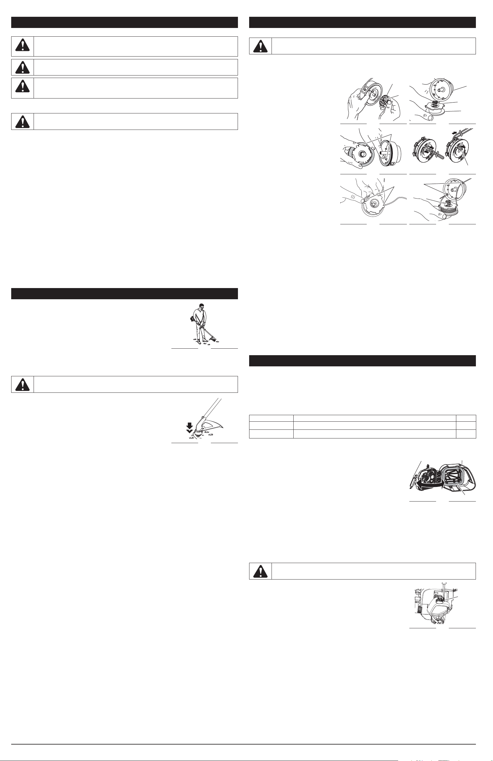
Reload The Line*
Spool
Spring
Inner
Reel
Bump
Knob
11 2
Unscrew bump knob
counterclockwise. Remove
inner reel and spring.
throttle for ALL further
steps.
3"-4
"
Insert 10' of 0.080"
®
SplitLine
through hole in top
of reel. Pull most of line
through hole until 3"-4"
remains.
Choke Lever
5 X
10
Pull rope 5 times. Move choke lever to
3
Bend short end and push it
into the other hole. Pull tight.
11
Position 2 and squeeze
throttle.
4
Wind line tightly in direction
of arrow. Split other end of
®
SplitLine
back 6"-7".
12
Pull rope 3-5 times to start
engine. Run unit for 30-60
seconds to warm up.
5
Push 6"-7" ends into 0.080"
holding slots.
3-5 X
Choke Lever
13
Continue to squeeze
throttle. Move choke lever
to Position 3.
6
Insert or slide lines into the
eyelets in spool. Insert spring
and reel into spool.
14
Continue to squeeze
throttle. Run unit for an
additional 60 seconds to
complete warm-up. Unit
may be used during this
time.
7
Pull lines firmly to release
from holding slots.
FRANÇAIS — PAGE 5
Reload The Line
18
Hold the inner reel in place.
Tighten Bump Knob
clockwise.
Replacement SplitLine® :
Part #49U2134K953
For single line installation, refer to Line Installation
section of this manual.
For replacement spool installation, refer to
Installing a Prewound Reel section of this manual.
*This is to assist in the reloading of Splitline® only. These instructions
are NOT part of the fast assembly instructions. Line does not need to
be installed on the initial assembly and start-up.
ESPAÑOL — PAGE 9
IMPORTANT: READ OPERATOR’S MANUAL THOROUGHLY AND FOLLOW THE SAFE OPERATION PRACTICES WHILE OPERATING THE UNIT.
NEED HELP? Call 1-800-800-7310 in U.S. or 1–800–668–1238 in Canada
769-07118 P00 04/11
Page 2
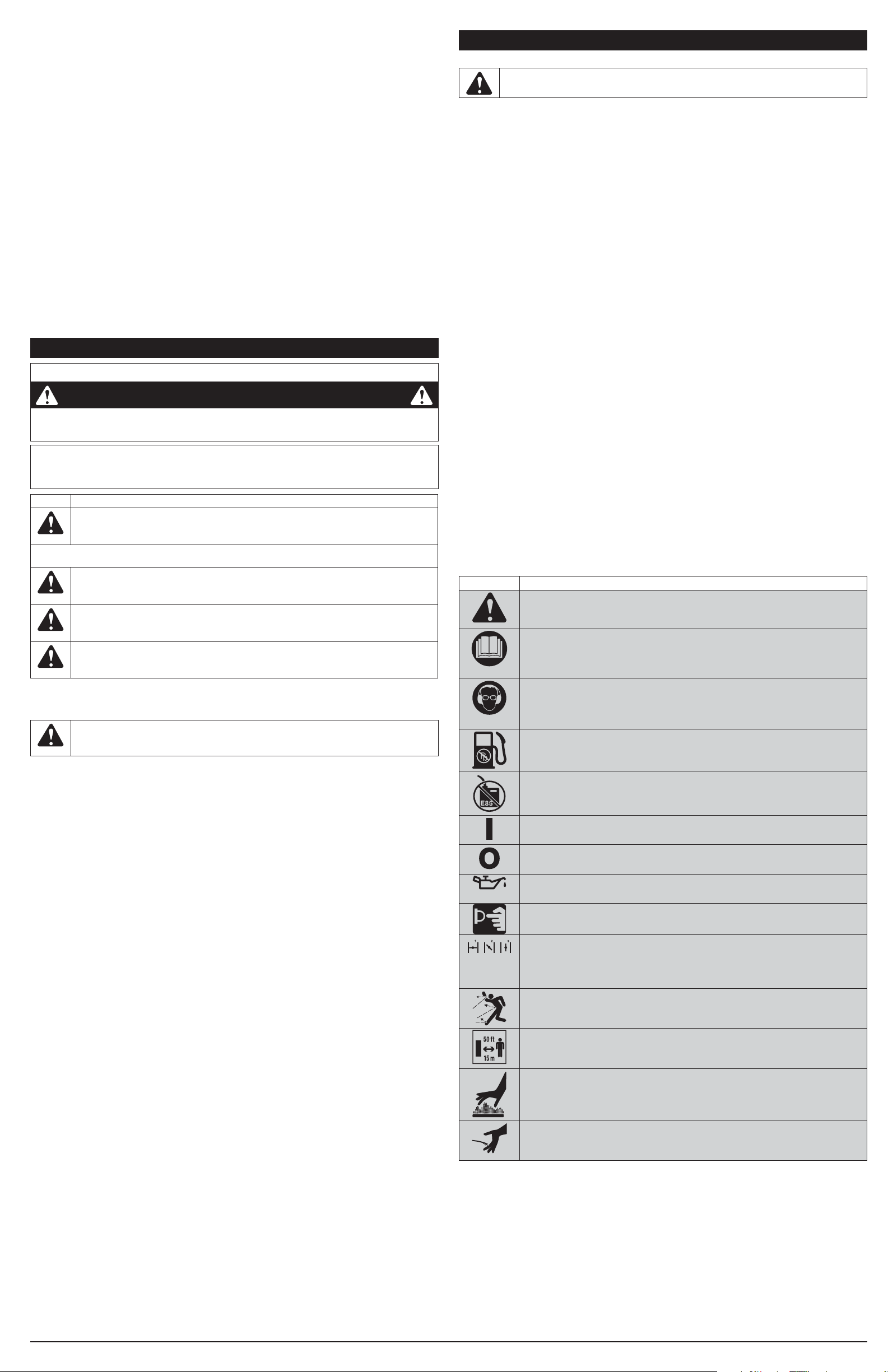
TABLE OF CONTENTS
Rules for Safe Operation ........................................................................................................................ 2
Oil and Fuel ............................................................................................................................................ 3
Operating ...............................................................................................................................................3
Maintenance ..........................................................................................................................................3
Cleaning and Storage ............................................................................................................................4
Troubleshooting .....................................................................................................................................4
Specifi cations ........................................................................................................................................ 4
For service, call 1-800-800-7310 in the United States or 1-800-668-1238 in Canada to obtain a
list of authorized service dealers near you. For more details about your unit, visit our website at
www.yardmachines.com or www.yardmachines.ca.
DO NOT RETURN THE UNIT TO THE RETAILER. PROOF OF PURCHASE WILL BE REQUIRED FOR
WARRANTY SERVICE.
Service on this unit both within and after the warranty period should be performed only by an authorized
and approved service dealer.
All information, illustrations, and specifi cations in this manual are based on the latest product information
available at the time of printing. We reserve the right to make changes at any time without notice.
Copyright© 2010 MTD SOUTHWEST INC, All Rights Reserved.
SPARK ARRESTOR NOTE
NOTE: For users on U.S. Forest Land and in the states of California, Maine, Oregon and Washington.
All U.S. Forest Land and the state of California (Public Resources Codes 4442 and 4443), Oregon and
Washington require, by law that certain internal combustion engines operated on forest brush and/or grasscovered areas be equipped with a spark arrestor, maintained in effective working order, or the engine be
constructed, equipped and maintained for the prevention of fi re. Check with your state or local authorities
for regulations pertaining to these requirements. Failure to follow these requirements could subject you to
liability or a fi ne. This unit is factory equipped with a spark arrestor. If it requires replacement, ask your
LOCAL SERVICE DEALER to install the Accessory Part #753-06418 Muffl er Assembly
RULES FOR SAFE OPERATION
CALIFORNIA PROPOSITION 65 WARNING
WARNING
THE ENGINE EXHAUST FROM THIS PRODUCT CONTAINS CHEMICALS KNOWN TO THE STATE
OF CALIFORNIA TO CAUSE CANCER, BIRTH DEFECTS OR OTHER REPRODUCTIVE HARM
The purpose of safety symbols is to attract your attention to possible dangers. The safety symbols,
and their explanations, deserve your careful attention and understanding. The safety warnings do not
by themselves eliminate any danger. The instructions or warnings they give are not substitutes for
proper accident prevention measures.
SYMBOL MEANING
SAFETY ALERT: Indicates danger, warning or caution. Attention is required in
order to avoid serious personal injury. May be used in conjunction with other symbols or
pictographs.
NOTE: Advises of information or instructions vital to the operation or maintenance of the
equipment.
DANGER: Failure to obey a safety warning will result in serious injury to yourself or to
others. Always follow the safety precautions to reduce the risk of fi re, electric shock and
personal injury.
WARNING: Failure to obey a safety warning can result in injury to yourself and others.
Always follow the safety precautions to reduce the risk of fi re, electric shock and personal
injury.
CAUTION: Failure to obey a safety warning may result in property damage or personal
READ ALL INSTRUCTIONS BEFORE OPERATING
GENERAL SAFETY
injury to yourself or to others. Always follow the safety precautions to reduce the risk of
fi re, electric shock and personal injury.
• IMPORTANT SAFETY INSTRUCTIONS •
WARNING: When using the unit, all safety rules must be followed. Please read these
instructions before operating the unit in order to ensure the safety of the operator and any
bystanders. Please keep these instructions for later use.
• Read the instructions carefully. Be familiar with the controls and proper use of the unit.
• Keep these instructions. Refer to them often and use them to instruct other users. If loaning this
unit to others, also loan them these instructions.
• Do not operate this unit when tired, ill or under the infl uence of alcohol, drugs or medication.
• Children and teens under the age of 15 must not use the unit, except teens guided by an adult.
• Use the right tool. Only use this tool for its intended purpose.
• Use the unit only in daylight or good artifi cial light.
• Wear safety glasses or goggles that meet ANSI Z87.1 standards and are marked as such. Wear
ear/hearing protection when operating this unit. Wear a face or dust mask if the operation is dusty.
• Wear heavy long pants, boots, gloves and a long sleeve shirt. Do not wear loose clothing, jewelry,
short pants, sandals or go barefoot. Secure hair above shoulder level.
• Inspect the unit before use. Replace damaged parts. Make sure all fasteners are in place and
secure. Replace parts that are cracked, chipped or damaged in any way. Do not operate the unit
with loose or damaged parts.
• All guards and safety attachments must be installed properly before operating the unit.
• Use only manufacturers recommended replacement parts or accessories for this unit. Use of
any replacement parts or accessories purchased elsewhere may be hazardous, and will void the
warranty.
• Be aware of risk of injury to the head, hands and feet.
• Clear the area of children, bystanders and pets; keep them outside a 50-foot (15 m) radius, at a
minimum. Even then, they are still at risk from thrown objects. Encourage bystanders to wear eye
protection. If approached, stop the unit immediately.
• Carefully inspect the area before starting the unit. Remove all debris such as rocks, broken glass,
nails, wire, string and other objects which may be thrown or become entangled in the unit.
• Squeeze the throttle control and check that it returns automatically to the idle position. Make all
adjustments or repairs before using the unit.
• Always stop the unit when operation is delayed or when walking from one location to another.
• Always hold the unit with both hands when operating. Keep a fi rm grip on both handles or grips.
• Do not force the unit. It will do the job better and with less likelihood of injury at a rate for which it
was designed.
• Do not overreach or use from unstable surfaces such as ladders, trees, steep slopes, rooftops,
etc. Always keep proper footing and balance.
• Do not operate the unit faster than the speed needed to do the job. Do not run the unit at high
speed when not in use.
• If the unit strikes or becomes entangled with a foreign object, stop the unit immediately and
check for damage. Do not operate before repairing damage. Do not operate the unit with loose or
damaged parts.
• Keep unit clean of vegetation and other materials that may clog, gum or bind moving parts, which
may cause serious personal injury and or damage to the unit.
• Keep hands, face, and feet away from all moving parts. Do not touch or try to stop any moving
parts while they are in motion.
• Allow the unit to cool before storing or transporting. Be sure to secure the unit while transporting.
• Never douse or squirt the unit with water or any other liquid. Keep handles dry, clean and free from
debris. Clean after each use, see Cleaning and Storage instructions.
• Store the unit in a dry place, secured or at a height to prevent unauthorized use or damage. Keep
out of the reach of children.
RULES FOR SAFE OPERATION
OIL AND FUEL SAFETY
WARNING: Gasoline is highly fl ammable and its vapors can explode if ignited. Take
the following precautions:
• Store fuel only in containers specifi cally designed and approved for the storage of such materials.
• Always stop the engine and allow it to cool before fi lling the fuel tank. Never remove the fuel tank
cap or add fuel when the engine is hot. Never operate the unit without the fuel cap securely in
place.
• Always mix or add fuel in a clean, well-ventilated outdoor area where there are no sparks or
fl ames. Do not smoke.
• Never operate the unit without the fuel cap securely in place.
• Avoid creating a source of ignition for spilled fuel. Wipe up any spilled fuel from the unit
immediately before starting the unit. Move the unit at least 30 feet (9.1 m) from the fueling source
and site before starting the unit. Do not smoke.
• Never start or run the unit inside a closed room or building. Breathing exhaust fumes can be fatal.
Operate this unit only in a well-ventilated outdoor area.
• Check the unit for fuel leaks.
• Loosen the fuel tank cap slowly to relieve any pressure in the tank.
• Never store the unit with fuel in the tank, inside a building where fumes may reach an open fl ame
(pilot lights, etc.) or sparks (switches, electrical motors, etc.).
• To reduce fi re hazard, replace a faulty muffl er and spark arrestor. Keep the engine and muffl er free
from grass, leaves, excessive grease or carbon build up.
• Avoid accidental starting. Be in the starting position whenever pulling the starter rope. The
operator and unit must be in a stable position while starting.
• Do not touch the engine, gear housing or muffl er. These parts get extremely hot from operation,
even after the unit is turned off.
• Turn the engine to off and disconnect the spark plug for maintenance or repair.
TRIMMER SAFETY
• The trimmer attachment shield must always be in place while operating the unit. Do not operate
unit without both trimming lines extended, and the proper line installed. Do not extend the
trimming line beyond the length of the shield.
• Adjust the D-handle that provides the best possible grip.
• Be sure the trimmer attachment is not in contact with anything before starting the unit.
• Use only 0.080 in. (2.03 mm) diameter replacement line. Never use metal-reinforced line, wire,
chain or rope. These can break off and become dangerous projectiles.
• Keep unit clean of vegetation and other materials. They may become lodged between the trimmer
attachment and shield.
• Keep hands, face, and feet away from all moving parts. Do not touch or try to stop the trimmer
attachment when it rotates.
SAVE THESE INSTRUCTIONS
• SAFETY & INTERNATIONAL SYMBOLS •
This operator’s manual describes safety and international symbols and pictographs that may
appear on this product. Read the operator’s manual for complete safety, assembly, operating and
maintenance and repair information.
SYMBOL MEANING
• SAFETY ALERT SYMBOL
Indicates danger, warning or caution. May be used in conjunction with other
symbols or pictographs.
• READ OPERATOR’S MANUAL
WARNING: Read the operator’s manual(s) and follow all warnings and safety
instructions. Failure to do so can result in serious injury to the operator and/or
bystanders.
• WEAR EYE AND HEARING PROTECTION
WARNING:
Thrown objects and loud noise can cause severe eye injury and hearing
loss. Wear eye protection meeting ANSI Z87.1-1989 standards and ear protection when
operating this unit. Use a full face shield when needed.
• UNLEADED FUEL
Always use clean, fresh unleaded fuel
• DO NOT USE E85 FUEL IN THIS UNIT
WARNING: It has been proven that fuel containing greater than 10% ethanol
will likely damage this engine and void the warranty.
• ON/OFF CONTROL
ON / START / RUN
• ON/OFF CONTROL
OFF or STOP
• OIL
Refer to operator’s manual for the proper type of oil.
• PRIMER BULB
Push primer bulb, fully and slowly, 10 times.
• CHOKE CONTROL
1. • FULL choke position
2. • PARTIAL choke position
3. • RUN choke position
• THROWN OBJECTS AND ROTATING CUTTER CAN CAUSE SEVERE INJURY
WARNING: Small objects can be propelled at high speed, causing injury. Keep
away from the rotating rotor.
• KEEP BYSTANDERS AWAY
WARNING: Keep all bystanders, especially children and pets, at least 50 feet
(15 m) from the operating area.
• HOT SURFACE
WARNING: Do not touch any metal engine components. The engine gets
extremely hot from operation and may cause severe burns. Allow the unit to
completely cool prior to any maintenance or servicing.
• SHARP BLADE
WARNING: Sharp blade on cutting attachment shield. To prevent serious
injury, do not touch the line cutting blade.
IMAGES MAY OR MAY NOT RESEMBLE ACTUAL PRODUCT.
2
Page 3
OIL AND FUEL
OIL AND FUEL MIXING INSTRUCTIONS
WARNING: Gasoline is extremely fl ammable. Ignited vapors may explode. Always stop
the engine and allow it to cool before fi lling the fuel tank. Do not smoke while fi lling the
tank. Keep sparks and open fl ames at a distance from the area.
WARNING:
Remove fuel cap slowly to avoid injury from fuel spray. Never operate the unit
without the fuel cap securely in place.
WARNING: Add fuel in a clean, level and well ventilated outdoor area. Wipe up any
spilled fuel immediately. Avoid creating a source of ignition for spilled fuel. Do not start the
engine until fuel vapors dissipate.
Be sure to use fresh, clean unleaded fuel and follow instructions carefully for proper fuel/oil mixture.
Defi nition of Blended Fuels
WARNING: Fuel containing greater than 10% ethanol will likely damage the engine and
void the warranty.
Today’s fuels are often a blend of gasoline and oxygenates such as ethanol, methanol, or MTBE (ether)
which absorb water. Use fuel within 30 days of purchase. Blended fuels older than 30 days will affect
the performance and life of the engine.
Using Blended Fuels
If the use of blended fuel is unavoidable, follow recommended precautions:
• Always use the fresh fuel mix explained in the operator’s manual
• Always agitate the fuel mix before fueling the unit
• Drain the tank and run the engine dry before storing the unit
Using Fuel Additives
It is recommended to use the manufacturers 2-cycle oil with this unit. If unavailable, use a good
2-cycle oil designed for air-cooled engines along with a fuel additive, such as STA-BIL® Gas Stabilizer
or an equivalent.
Add 0.8 oz. (23 ml) of fuel additive per gallon of fuel according to the instructions on the container.
NEVER add fuel additives directly to the unit’s fuel tank.
Mixing The Fuel
Thoroughly mix the proper ratio of 2-cycle engine oil with unleaded fuel in a separate fuel can. Use a
40:1 fuel/oil ratio. Do not mix them directly in the engine fuel tank.
IF... the unit came with a bottle of 2-cycle oil; pour the entire bottle into 1 gallon of gas and mix
thoroughly.
NOTE: One gallon (3.8 liters) of unleaded fuel mixed with one 3.2 oz. (95 ml) bottle of 2-cycle oil
makes a 40:1 fuel/oil ratio.
NOTE: Dispose of the old fuel/oil mix in accordance to Federal, State and Local regulations.
OPERATION
HOLDING THE UNIT
Before operating the unit, stand in the operating position (Fig. 1). Check
for the following:
• The operator is wearing eye protection and proper clothing
• With a slightly-bent right arm, the operator’s hand is holding the
shaft grip
• The operator’s left arm is straight, the left hand holding the
D-handle
• The unit is at waist level
• The cutting head is parallel to the ground and easily contacts the grass without the need to bend
Fig. 1
over
ADJUSTING TRIMMING LINE LENGTH
WARNING: Do not remove or alter the line cutting blade assembly. Excessive line
length will cause premature engine failure and / or unit damage.
The Bump Head™ cutting head allows the release of trimming line
without stopping the engine. To release more line, lightly tap the cutting
head on the ground (Fig. 2) while operating the unit at high speed.
Each time the head is bumped, about 1 inch (25.4 mm) of trimming
line releases. A blade in the cutting head shield will cut the line to the
proper length if any excess line is released.
NOTE: Always keep trimming line fully extended. Line release
For best results, tap bump knob on bare ground or hard soil. If
attempting a line release in tall grass, engine may stall.
NOTE: Do not rest the Bump Head™ on the ground while the unit is running.
BEST TRIMMING RESULTS
• Keep the cutting head parallel to the ground.
• Do not force the cutting head. Allow the tip of the line to do the cutting, especially along walls.
• Cut grass over 8 inches (200 mm) by working from top to bottom in small increments to avoid
• Cut from right to left whenever possible. Cutting to the left improves the unit’s cutting effi ciency.
• Slowly move the unit into and out of the cutting area at the desired height. Move either in a
• Trim only when grass and weeds are dry.
The life of the cutting line is dependent upon:
• Following the trimming techniques
• What vegetation is being cut
• Where vegetation is cut
For example, the line will wear faster when trimming against a foundation wall as opposed to trimming
around a tree.
becomes more diffi cult when the cutting line gets shorter.
Fig. 2
Cutting with more than the tip will reduce cutting effi ciency and may overload the engine.
premature line wear or engine drag.
Clippings are thrown away from the operator.
forward-backward or side-to-side motion. Cutting shorter lengths produces the best results.
LINE INSTALLATION
LINE INSTALLATION
WARNING: Never use metal-reinforced line, wire, chain or rope. These can break off
and become dangerous projectiles.
Always use original equipment manufacturer 0.080 in. (2.03 mm) replacement line. Line other than the
specifi ed may void warranty.
LINE INSTALLATION
Removing the Spool
1. Hold reel and unscrew bump knob
(Fig. 3). Inspect bump knob bolt to
make sure it moves freely. Replace
bump knob if damaged.
2. Remove spool and spring (Fig. 4).
Bump Knob
Bolt
Spool
Spring
Reel
3. Using a clean cloth, clean spool,
spring, shaft, and inner surface of
the reel.
4. Check indexing teeth on spool and
Fig. 3
Fig. 4
Index Teeth
reel for wear (Fig. 5). If necessary,
replace.
NOTE: Always use correct line length
when installing trimming line.
Line may not release properly
if too long.
Single Line Installation
Go To Front Cover for SplitLine®
Installation:
5. Using 20 feet (6 m) of new line, loop
into two equal lengths. Insert each
Fig. 5
Index Teeth
Fig. 6
Eyelets
Spring
Loop
end of the line through the holes on
the spool (Fig. 6). Pull line through
so that the loop is as small as
possible.
6. Wind line in tight even layers and in
Fig. 7
Fig. 8
the direction as indicated on spool.
Place index fi nger between both lines to keep from overlapping while winding.
7. Insert ends of line into appropriate holding slots (Fig. 7).
8. Insert or slide ends of line through eyelets and place spool with spring inside reel (Fig. 8). Push the
spool and reel together.
NOTE: Spring must be assembled on spool prior to reassembly.
9. While holding spool and reel, grasp ends of line and pull fi rmly to release.
10. Hold reel in place and install bump knob by turning clockwise. Tighten securely.
Installing a Prewound Spool
1. Hold reel with one hand and unscrew bump knob (Fig. 3). Inspect bump knob bolt to make sure it
moves freely. Replace bump knob if damaged.
2. Remove spool from reel and spring from spool (Fig. 4).
3. Place spring in replacement spool.
NOTE: Spring must be assembled on spool prior to reassembly.
4. Insert or slide ends of the line into eyelets on reel (Fig. 8).
5. Place replacement spool inside reel and push together. While holding spool and reel, grasp line
ends and pull fi rmly to release.
6. Hold the reel in place and install the bump knob by turning clockwise. Tighten securely.
MAINTENANCE
MAINTENANCE SCHEDULE
Perform these required maintenance procedures at the frequency stated in the table. These
procedures should also be a part of any seasonal tune-up.
NOTE: Some maintenance procedures may require special tools or skills. For these types of repairs
call 1-800-800-7310 for more information.
NOTE: Please read the California/ EPA statement that came with the unit for a complete listing of
terms and coverage for the emissions control devices, such as the spark arrestor, muffl er,
carburetor, etc.
FREQUENCY MAINTENANCE REQUIRED SEE
Every 10 hours Clean and re-oil air fi lter p. 3
Every 25 hours Check spark plug condition and gap p. 4
AIR FILTER MAINTENANCE
Cleaning the Air Filter
Failure to maintain the air fi lter properly can result in poor performance
Lock Tab
Air Filter Cover
or can cause permanent damage to the engine.
1. Open the air fi lter cover and remove the air fi lter (Fig. 9).
2. Wash the fi lter in detergent and water. Rinse thoroughly and allow
to dry.
3. Apply clean SAE 30 motor oil to fi lter.
4. Squeeze fi lter to spread and remove excess oil.
5. Replace air fi lter into air fi lter cover (Fig. 9).
Fig. 9
Air Filter
NOTE: Operating unit without air fi lter WILL VOID warranty.
6. Reinstall the air fi lter cover and press down until it snaps into place (Fig. 9).
IDLE SPEED ADJUSTMENT
Idle speed of the engine is adjustable. An idle adjustment screw is between the air fi lter cover and
engine starter housing (Fig. 10).
NOTE: Careless adjustments can damage unit. An authorized service dealer should make
carburetor adjustments.
After checking the fuel mixture and cleaning the air fi lter, the engine still will not idle. Adjust the idle
speed screw as follows:
WARNING: Cutting head will spin during idle speed adjustments. Wear protective
clothing and observe all safety instructions to prevent serious personal injury.
1. Start the engine and run for one minute.
2. Release throttle trigger and let the engine idle. If engine stops,
insert a small phillips screwdriver into the idle adjustment screw and
turn clockwise 1/8 of a turn at a time until engine idles smoothly.
3. If the engine appears to be idling too fast, turn the screw
counterclockwise 1/8 of a turn at a time to reduce idle speed.
Checking fuel mixture, cleaning air fi lter and adjusting idle speed should
solve most engine problems. If not and the following are true:
• engine will not idle
• engine hesitates or stalls on acceleration
• there is a loss of engine power
Have the carburetor adjusted by an approved service dealer.
Fig. 10
Idle Speed
Screw
3
Page 4

MAINTENANCE TROUBLESHOOTING
REPLACING THE SPARK PLUG
Use replacement #753-06193, a Champion RDJ7J spark plug, or equivalent. The correct air gap is
0.025 inch (0.635 mm).
1. Stop the engine and allow it to cool.
2. Grasp plug wire fi rmly and pull.
3. Clean around spark plug and remove using a 5/8-inch socket counterclockwise.
WARNING: Do not sand blast, scrape or clean
electrodes. Grit in the engine could damage the cylinder.
4. Set the air gap, according to specifi cations, using a feeler gauge
(Fig. 11).
5. Install spark plug turning clockwise and torquing as stated:
• Torque to: 110-120 in.•lb. (12.3-13.5 N•m) Do not over tighten.
CLEANING
Do not use strong detergents or household cleaners that contain aromatic oils such as pine and
lemon, or solvents such as kerosene, which can damage plastic housing or handle. Use a small brush
to clean unit and wipe off any moisture with a soft cloth.
STORAGE
• Never store a fueled unit where fumes may reach an open fl ame or spark.
• Allow the engine to cool before storing.
• Store the unit locked up to prevent unauthorized use or damage.
• Store the unit in a dry, well-ventilated area.
• Store the unit out of the reach of children.
LONG TERM STORAGE
If planning on storing the unit for 30 days or more, use the following storage procedure:
1. Drain all fuel from fuel tank into a container and dispose in accordance with Federal, State and
Local regulations.
2. Start the engine and allow it to run until it stalls to ensure that all fuel has been drained from the
engine and allow to cool.
3. Remove the spark plug and put 3 - 5 drops of motor oil into cylinder. Pull starter rope slowly to
distribute oil and reinstall the spark plug.
NOTE: Remove spark plug and drain all oil from cylinder before attempting to start unit after
storage.
4. Thoroughly clean unit and inspect for any loose or damaged parts. Repair or replace parts and
tighten loose screws, nuts or bolts.
0.025 in.
(0.635 mm)
Fig. 11
PROBLEM SOLUTION
ENGINE WILL NOT START, IDLE OR ACCELERATE
Empty fuel tank Fill fuel tank with fuel
Primer bulb wasn't pr
essed enough Slowly press primer bulb 10 times
Old fuel Drain gas tank and add fresh fuel
Fouled spark plug Replace or clean the spark plug
Air fi lter is plugged Replace or clean the air fi lter
Improper idle speed
Adjust according to the Idle Speed
Adjustments section.
ENGINE LACKS POWER OR STALLS
Old fuel Drain gas tank and add fr
esh fuel
Fouled spark plug Replace or clean the spark plug
CUTTING HEAD WILL NOT ADVANCE LINE OR ADVANCES UNCONTROLLABLY
Cutting head bound with grass Stop engine and clean cutting head
Cutting head out of line
Refi ll with new line
Inner reel bound up Rewind inner reel
Cutting head dirty Clean inner reel and outer spool
Line welded
Disassemble, remove the welded section and
rewind
Line twisted when refi lled Disassemble and rewind the line
Push bump knob and pull line out until 4
Not enough line is exposed
inches (102 mm) of line is exposed from cutting
head
Oil, cleaner or lubricant in cutting head Clean and thoroughly dry the cutting head
SPECIFICATIONS
UNIT*
Engine Type .............................................................................................................. Air-Cooled, 2-Cycle
Displacement .................................................................................................................................. 25 cc
Operating RPM ........................................................................................................................6,300 rpm
Idle Speed RPM ..........................................................................................................3,200 – 4,400 rpm
Spark Plug Gap .................................................................................................... 0.025 inch (0.635 mm)
Lubrication .....................................................................................................................Fuel/ Oil Mixture
Fuel/ Oil Ratio ...................................................................................................................................40:1
Fuel Tank Capacity .........................................................................................................10 fl .oz. (296 ml)
Approximate Unit Weight (No fuel) ......................................................................10 - 11 lbs. (4.5 - 5 kg)
Trimming Line Diameter ............................................................................................ 0.080 in. (2.03 mm)
Cutting Path Diameter .................................................................................................. 17 in. (43.18 cm)
* All specifi
cations are based on the latest product information available at the time of printing. We
reserve the right to make changes at any time without notice.
4
Page 5

Y60
Manuel de l’utilisateur
Coupe-bordure 2 temps
Retirer l’appareil du carton
11 2
Retirez tous les éléments
du carton.
Assembler l’appareil
40:1
1 Gallon 3.2 oz
4 5 6
Mélangez soigneusement
dans un bidon d’essence :
– 0,09 litre (3,2 oz.) d’huile
pour moteur 2 temps
– 3,8 litres (1 gallon)
d'essence sans plomb
REMARQUE : ne faites pas le
mélange directement dans
le réservoir de carburant.
Démarrer l’appareil
Assembler l’appareil
Placez l’écran de protection sur le
support de montage. Serrez
fermement les 2 vis de l’écran de
protection à travers les trous du
support de montage et dans l’écran de
protection. Assurez-vous que les vis
sont serrées à la même force, de façon
à avoir un espace égal entre le support
de montage et l’écran de chaque côté.
Placez l’appareil sur une
surface plane et remplissez
le réservoir de carburant.
VEILLEZ À NE PAS trop le
remplir.
Min. 6"
3
Placez la poignée sur
l’arbre. Déplacez la poignée
à au moins 15 cm (6
pouces) de la poignée de
l’arbre. Insérez les boulons
et serrez-les.
Démarrer l’appareil
Poire
d’amorçage
10 X
Pressez la poire
d’amorçage 10 fois ou
jusqu’à ce que le carburant
soit visible.
Levier d’étranglement
7
Mettez le levier
d’étranglement en position 1.
Levier d’étranglement
Outils requis :
• Tournevis cruciforme n°2
Cordon de démarrage
Bouton marche/arrêt (On/Off)
Poignée en D
Écran de protection
de la tête de coupe
Tête de coupe
Levier d’étranglement
Bougie
Levier d’étranglement
Couvercle du filtre à air
Poire d’amorçage
Bouchon du
réservoir de
carburant
Manette des gaz
L’APPAREIL NE
DÉMARRE PAS ?
SI... le moteur ne démarre pas,
retournez à l’étape 6.
SI le moteur ne démarre pas après 2
tentatives, placez le levier
d’étranglement en position 3 et tirez le
cordon de démarrage jusqu’à ce que le
SI le moteur fait des accrocs, remettez
le levier d’étranglement en position 2 et
REMARQUE : l’appareil est suffisam-
ment chaud lorsque le moteur accélère
moteur démarre.
continuez de chauffer le moteur.
sans accrocs.
ENGLISH — PAGE 1
18 9
Placez-vous en position de
démarrage.
Recharger le fil*
Bobine
Ressort
Enrouleur
intérieur
Bouton
11 2
Dévissez le bouton de butée
dans le sens contraire des
aiguilles d’une montre.
Retirez l’enrouleur intérieur
et le ressort.
Recharger le fil
18
Maintenez l’enrouleur
intérieur en place. Serrez le
bouton de butée dans le sens
des aiguilles d’une montre.
de butée
10
MAINTENEZ la manette des
gaz ENFONCÉE TOUT AU
LONG des étapes suivantes.
3"-4
"
Insérez 3 m (10 pieds) de fil de
2,03 mm (0,080 pouce)
®
SplitLine
à travers le trou
au-dessus de l’enrouleur. Faites
passer le fil dans le trou jusqu’à
ce qu’il ne reste qu’environ 7,6 à
10 cm (3 à 4 pouces).
SplitLine® de rechange :
N° de pièce : 49U2134K953
Pour l’installation d’un fil simple, consultez la
section Installation du fil de coupe de ce manuel.
Pour l’installation d’une bobine de rechange,
consultez la section Installation d’une bobine
pré-embobinée de ce manuel.
**Ces consignes ont uniquement pour but de vous aider à recharger
du fil Splitline®. Elles ne font PAS partie des instructions
d’assemblage rapide. Il n’est pas nécessaire que le fil soit installé lors
du montage initial et du premier démarrage.
Tirez 5 fois sur le cordon.
3
Pliez l’extrémité la plus courte
et enfoncez-la dans l’autre
trou. Tirez fort.
5 X
11
Mettez le levier
d’étranglement en
position 2 et pressez la
manette des gaz.
4
Rembobinez bien le fil dans la
direction de la flèche.
Séparez l’autre extrémité du
fil SplitLine
18 cm (6 à 7 pouces).
®
en deux sur 15 à
12
Tirez sur le cordon 3 à 5
fois de suite pour démarrer
le moteur. Laissez tourner le
moteur 30 à 60 secondes
pour le réchauffer.
5
Poussez les extrémités de 15
à 18 cm (6 à 7 pouces) dans
les fentes de retenue de 2,03
mm (0,080 pouce).
3-5 X
13
Continuez de presser la
manette des gaz. Mettez le
levier d’étranglement en
position 3.
6
Insérez ou faites glisser les
fils dans les œillets de la
bobine. Insérez le ressort et
l’enrouleur dans la bobine.
14
Continuez de presser la
manette des gaz. Laissez
tourner le moteur encore
60 secondes pour terminer
le réchauffage. L’appareil
peut être utilisé pendant ce
temps.
7
Tirez bien les fils pour les
libérer des fentes de retenue.
FRANÇAIS — PAGE 5
ESPAÑOL — PAGE 9
IMPORTANT : LISEZ ATTENTIVEMENT LE MANUEL DE L’UTILISATEUR ET CONFORMEZ-VOUS AUX INSTRUCTIONS POUR UNE UTILISATION DE L’APPAREIL EN TOUTE SÉCURITÉ.
BESOIN D’AIDE ? Appelez le 1-800-800-7310 aux États-Unis ou le 1–800–668–1238 au Canada
769-07118 P00 04/11
5
Page 6

TABLE DES MATIÈRES
Règles pour une utilisation en toute sécurité ......................................................................................... 6
Huile et carburant ..................................................................................................................................7
Utilisation ...............................................................................................................................................7
Entretien .............................................................................................................................................7-8
Nettoyage et rangement ........................................................................................................................ 8
Résolution des problèmes .....................................................................................................................8
Spécifi cations ........................................................................................................................................ 8
Pour un entretien ou une réparation, appelez le 1-800-800-7310 aux États-Unis ou le 1-800-668-
1238 au Canada pour obtenir une liste complète des concessionnaires agréés près de chez vous.
Pour plus de renseignements sur votre appareil, visitez notre site web www.yardmachines.com ou
www.yardmachines.ca.
NE RAMENEZ PAS CET APPAREIL CHEZ LE DÉTAILLANT. UNE PREUVE D’ACHAT SERA EXIGÉE
POUR TOUTE PRISE EN CHARGE DANS LE CADRE DE LA GARANTIE.
L’entretien de cet appareil doit être confi é uniquement à un concessionnaire agréé pendant et après la
période de garantie.
Toutes les informations, illustrations et caractéristiques sont basées sur les toutes dernières
informations disponibles sur le produit, à l’impression de ce guide. Nous nous réservons le droit
d’effectuer des modifi cations à tout moment sans notifi cation préalable.
Copyright© 2010 MTD SOUTHWEST INC. Tous droits réservés.
REMARQUE CONCERNANT LE PARE-ÉTINCELLE
REMARQUE : À l'intention des utilisateurs utilisant l’appareil dans les terres forestières des États-
Unis et dans les états de Californie, du Maine, de l'Oregon et de Washington. Toutes les terres
forestières des États-Unis et de l'état de Californie (Codes sur les ressources publiques 4442 et 4443),
de l'Oregon et de Washington exigent de par la loi que certains moteurs à combustion interne utilisés
dans des zones couvertes de taillis et/ou d'herbes soient équipés d'un pare-étincelles en parfait état
de fonctionnement, ou qu'ils soient conçus, équipés et entretenus pour la prévention des incendies.
Renseignez-vous auprès des autorités locales ou régionales concernant la réglementation en vigueur.
Vous pourriez être passible d'une amende ou être tenu responsable si vous ne respectez pas cette
réglementation. Cet appareil est équipé d'un pare-étincelle en usine. Si l'écran du pare-étincelle, réf.
753-06418, doit être remplacé, contactez votre RÉPARATEUR LOCAL AGRÉÉ.
RÈGLES POUR UNE UTILISATION EN TOUTE SÉCURITÉ
AVERTISSEMENT RELATIF À LA PROPOSITION 65 DE L’ÉTAT DE CALIFORNIE
AVERTISSEMENT
LES GAZ D'ÉCHAPPEMENT DU MOTEUR DE CET APPAREIL CONTIENNENT DES PRODUITS CHIMIQUES
CONSIDÉRÉS PAR L'ÉTAT DE CALIFORNIE COMME POUVANT PROVOQUER DES CANCERS, DES
MALFORMATIONS CONGÉNITALES OU D'AUTRES EFFETS NOCIFS SUR LA REPRODUCTION.
L’objectif de ces symboles de sécurité est d’attirer votre attention sur des dangers potentiels. Ces
symboles de sécurité et leurs explications méritent que vous les lisiez et compreniez bien. Les seuls
avertissements de sécurité n’éliminent pas le danger. Les consignes ou avertissements de sécurité ne
remplacent pas les mesures appropriées de prévention des accidents.
SYMBOLE SIGNIFICATION
ALERTE DE SÉCURITÉ : Indique un danger, un avertissement ou une mise en
garde. Soyez vigilant afi n d'éviter toute blessure grave. Ce symbole peut être combiné à
d'autres symboles ou pictogrammes.
REMARQUE : Vous donne des informations ou des instructions capitales pour l’utilisation ou
l’entretien de l’équipement.
DANGER : Le non-respect d’une consigne de sécurité entraînera des blessures graves
pour vous-même ou pour les autres. Respectez toujours les consignes de sécurité pour
réduire les risques d’incendie, de choc électrique et de blessures corporelles.
AVERTISSEMENT : Le non-respect d’une consigne de sécurité peut entraîner
des blessures pour vous-même ou pour les autres. Respectez toujours les consignes
de sécurité pour réduire les risques d’incendie, de choc électrique et de blessures
corporelles.
ATTENTION : Le non-respect d’une consigne de sécurité peut entraîner des dégâts
matériels ou des blessures graves pour vous-même ou pour les autres. Respectez
toujours les consignes de sécurité pour réduire les risques d’incendie, de choc électrique
et de blessures corporelles.
• CONSIGNES DE SÉCURITÉ IMPORTANTES •
LISEZ CETTE NOTICE INTÉGRALEMENT AVANT D’UTILISER L’APPAREIL
PRÉCAUTIONS DE SÉCURITÉ D’ORDRE GÉNÉRAL
AVERTISSEMENT : Lors de l’utilisation de l’appareil, respectez toutes les
consignes de sécurité. Veuillez lire ces consignes avant d’utiliser l’appareil afi n de garantir
votre sécurité et celle des personnes à proximité. Conservez-les pour vous y référer
ultérieurement.
• Lisez soigneusement cette notice. Familiarisez-vous avec les commandes et la marche à suivre pour une
bonne utilisation de l'appareil.
• Conservez ces instructions. Consultez-les régulièrement et utilisez-les pour donner des consignes aux
autres utilisateurs. Si vous prêtez cet appareil à quelqu’un, prêtez-lui également ces instructions.
• N’utilisez pas cet appareil lorsque vous êtes fatigué, malade ou sous l’infl uence de l’alcool, de drogues
ou de médicaments.
• L'appareil ne doit pas être utilisé par un enfant ou adolescent de moins de 15 ans, à moins que
l'adolescent soit sous la supervision d’un adulte.
• Utilisez les outils appropriés. N’employez cet outil que pour son usage prévu.
• Utilisez l’appareil uniquement en plein jour ou avec un bon éclairage artifi ciel.
• Portez des lunettes de sécurité conformes aux normes ANSI Z87.1, lesquelles doivent être indiquées sur
les lunettes mêmes. Portez une protection auditive lorsque vous utilisez cet appareil. Portez un masque
de protection pour le visage ou antipoussière si vous travaillez dans un endroit poussiéreux.
• Portez un pantalon long et épais, des bottes, des gants et une chemise à manches longues. Ne marchez
pas pieds nus et évitez de porter des vêtements amples, des bijoux, des pantalons courts et des
sandales. Relevez les cheveux au-dessus des épaules.
• Inspectez l’appareil avant utilisation. Remplacez les pièces endommagées. Assurez-vous que toutes
les attaches sont en place et solidement fi xées. Remplacez les pièces fi ssurées, ébréchées ou
endommagées. N’utilisez pas l’appareil avec des pièces endommagées ou détachées.
• Tous les dispositifs de protection et de sécurité doivent être correctement installés avant d'utiliser
l’appareil.
• Pour cet appareil, utilisez uniquement les pièces et accessoires de rechange recommandés par le
fabricant. L’utilisation de pièces de rechange ou accessoires non agréés pourrait être dangereuse et
entraînera l’annulation de votre garantie
• Soyez conscient des risques de blessure à la tête, aux mains et aux pieds.
• Au minimum, faites reculer les enfants, les personnes à proximité et les animaux domestiques de 15
m (50 pieds). Il existe néanmoins un risque de projectile pour les personnes à proximité. Encouragez
les personnes à proximité à porter des lunettes de sécurité. Si quelqu’un s’approche de vous, arrêtez
l’appareil immédiatement.
• Inspectez la zone avec attention avant de démarrer cet appareil. Retirez tous les débris, tels que des
bris de verre, des clous, des bouts de câbles, des bouts de corde et tout autre objet susceptible d'être
projeté ou emmêlé dans l’appareil.
• Appuyez sur la manette des gaz et vérifi ez que le régime du moteur revient automatiquement au ralenti.
Effectuez tous les réglages et toutes les réparations avant d’utiliser l’appareil.
• Arrêtez toujours l'appareil lorsque l’utilisation est interrompue ou lorsque vous vous déplacez d’un
endroit à l’autre.
• Tenez toujours l’appareil des deux mains lorsqu'il est en marche. Tenez fermement les deux poignées.
• Ne forcez pas l’appareil. Il sera plus effi cace et vous courrez moins de risques de blessures en l’utilisant
de façon adéquate.
• N’essayez pas d’atteindre des branches trop éloignées et évitez de vous tenir sur des surfaces trop
instables comme une échelle, un arbre, une pente raide, un toit, etc. Gardez toujours une position stable
et un bon équilibre.
• Ne faites pas tourner l'appareil à une vitesse supérieure à celle qui est nécessaire pour effectuer le
travail. Ne faites pas tourner l'appareil à haut régime lorsque vous ne l’utilisez pas.
• Si l’appareil heurte ou s'emmêle avec un objet, coupez le moteur immédiatement et vérifi ez que l’appareil
n’a pas été endommagé. N’utilisez pas l’appareil avant d’avoir réparé les dommages. N’utilisez pas
l’appareil avec des pièces endommagées ou détachées.
• Nettoyez bien l’appareil en éliminant toute trace de végétaux ou d'autres matériaux susceptibles
d'obstruer, de coller ou de coincer les pièces mobiles, ce qui peut causer des blessures graves ou
endommager l’appareil.
• Gardez les mains, le visage et les pieds éloignés des parties en mouvement. N’essayez pas de toucher
ou d’arrêter les parties mobiles lorsqu'elles sont en mouvement.
• Laissez refroidir l’outil avant de le ranger ou de le déplacer. Attachez bien l’appareil pendant le transport.
RÈGLES POUR UNE UTILISATION EN TOUTE SÉCURITÉ
AVERTISSEMENT : L’essence est extrêmement infl ammable et ses vapeurs peuvent
exploser si on y met le feu. Veuillez prendre les précautions suivantes :
• Ne mouillez et n'humidifi ez jamais l’appareil avec de l’eau ou un liquide quelconque. Conservez les
poignées sèches et propres. Nettoyez l’appareil après chaque utilisation ; consultez les Instructions de
nettoyage et rangement.
• Entreposez l’appareil dans un endroit sec éventuellement sous clef ou en hauteur pour éviter tout usage
non autorisé et pour éviter qu’il soit endommagé. Gardez toujours l’appareil hors de la portée des
enfants.
CONSIGNES DE SÉCURITÉ POUR L’HUILE ET LE CARBURANT
• Stockez uniquement le carburant dans des conteneurs prévus spécifi quement à cet effet et approuvés
pour le stockage de telles substances.
• Coupez toujours le moteur et laissez-le refroidir avant de remplir le réservoir d’essence. Ne retirez jamais
le bouchon du réservoir de carburant et ne remplissez jamais ce dernier lorsque le moteur est chaud. Ne
démarrez jamais l’appareil avant d’avoir bien revissé le bouchon du réservoir de carburant.
• Mélangez et ajoutez toujours le carburant en extérieur, dans une zone propre, bien aérée, à l'abri des
étincelles ou des fl ammes. Ne fumez pas.
• Ne démarrez jamais l’appareil avant d’avoir bien revissé le bouchon du réservoir de carburant.
• Évitez tout ce qui pourrait enfl ammer le carburant renversé. L’essence s’étant échappée de l’appareil
doit être essuyée immédiatement avant de démarrer l'appareil. Éloignez l’appareil d’au moins 9,1 m (30
pieds) du site et de la source du carburant avant de démarrer le moteur. Ne fumez pas.
• L'appareil ne doit pas être démarré ou utilisé à l'intérieur d'une pièce ou d’un bâtiment fermé. L’inhalation
des fumées d’échappement peut être mortelle. Utilisez cet appareil uniquement en extérieur, dans une
zone bien aérée.
• Assurez-vous que l'appareil ne présente pas de fuites de carburant.
• Dévissez lentement le bouchon du réservoir d’essence afi n de réduire la pression.
• N’entreposez jamais l’appareil avec de l’essence dans le réservoir à l’intérieur d’un bâtiment où les
vapeurs peuvent entrer en contact avec toute source de fl ammes (lampes témoin, etc.) ou d’étincelles
(interrupteurs, moteurs électriques, etc.).
• Afi n de réduire les risques d’incendie, remplacez les pare-étincelles et les pots d’échappement
défectueux. Nettoyez l’herbe, les feuilles, les couches de graisse excessives et les dépôts de carbone du
moteur et du pot d’échappement.
• Évitez les démarrages accidentels. Tenez-vous en position de démarrage lorsque vous tirez sur le cordon
de démarrage. L’utilisateur et l’appareil doivent se trouver dans une position stable lors du démarrage.
• Ne touchez pas au moteur, à la transmission ou au pot d'échappement. Ces pièces deviennent
extrêmement chaudes lors du fonctionnement, même après l'arrêt de l'appareil.
• Éteignez le moteur et débranchez la bougie pour effectuer son entretien ou sa réparation.
CONSIGNES DE SÉCURITÉ POUR LE COUPE-BORDURE
• L’écran du coupe-bordure doit toujours être en place lorsque vous vous servez de cet appareil. N'utilisez
jamais cet appareil sans une longueur suffi sante des deux fi ls de coupe, ces derniers devant être ceux
recommandés par le fabricant. La longueur du fi l de coupe ne doit jamais aller au-delà de celle de
l’écran.
• Réglez la poignée en D de manière à avoir la meilleure prise possible.
• Assurez-vous que l’accessoire de coupe-bordure n’est pas en contact avec tout autre élément avant de
démarrer l’appareil.
• Utilisez uniquement un fi l de coupe de rechange de 2,03 mm (0,08 pouce) de diamètre. N’utilisez jamais
de fi l, de câble, de chaîne ou de cordon à renfort métallique. Ces derniers peuvent céder et devenir des
projectiles dangereux.
• Nettoyez bien l’appareil en éliminant toute trace de végétaux ou d'autres matériaux susceptibles de se
coincer entre l’accessoire de coupe-bordure et l’écran.
• Gardez les mains, le visage et les pieds éloignés des parties en mouvement. Ne touchez pas et ne tentez
pas d'arrêter l'accessoire de coupe-bordure lorsqu'il est en rotation.
CONSERVEZ CES INSTRUCTIONS
• SYMBOLES INTERNATIONAUX ET DE SÉCURITÉ •
Ce manuel de l’utilisateur décrit les symboles et pictogrammes de sécurité internationaux qui peuvent
apparaître sur ce produit. Lisez ce manuel de l’utilisateur pour obtenir des informations complètes sur
la sécurité, l’assemblage, l’utilisation, l’entretien et les réparations.
SYMBOLE SIGNIFICATION
• SYMBOLE D’ALERTE DE SÉCURITÉ
Indique un danger, un avertissement ou une mise en garde. Ce symbole peut être
combiné à d'autres symboles ou pictogrammes.
• LISEZ LE MANUEL DE L’UTILISATEUR
AVERTISSEMENT : Lisez le(s) manuel(s) de l’utilisateur et respectez toutes
les consignes de sécurité et de prévention. Tout manquement peut entraîner des
blessures graves pour les utilisateurs et/ou pour les personnes à proximité.
• PORTEZ DES PROTECTIONS OCULAIRES ET AUDITIVES
AVERTISSEMENT :
Les objets projetés et le bruit peuvent entraîner de graves
lésions oculaires et pertes auditives. Portez toujours des protections oculaires conformes
aux normes ANSI Z87.1-1989 et des protections auditives lorsque vous utilisez cet outil.
Protégez-vous le visage avec un masque intégral au besoin.
• ESSENCE SANS PLOMB
Utilisez toujours de l’essence sans plomb fraîche et propre.
• N’UTILISEZ PAS d’ESSENCE E85 DANS CET APPAREIL.
AVERTISSEMENT : Il a été prouvé que l’utilisation de carburant contenant
plus de 10% d’éthanol endommagera très certainement ce moteur et annulera la
garantie.
• COMMANDE MARCHE/ARRÊT
MARCHE / DÉMARRAGE / FONCTIONNEMENT
• COMMANDE MARCHE/ARRÊT
ARRÊT ou STOP
• HUILE
Consultez le manuel de l’utilisateur pour connaître le type d’huile à utiliser.
• POIRE D’AMORÇAGE
Appuyez sur la poire d’amorçage lentement et complètement, dix (10) fois.
• COMMANDE D’ÉTRANGLEMENT
1. • Étrangleur en position COMPLÈTE
2. • Étrangleur en position PARTIELLE
3. • Étrangleur en position MARCHE
• LES OBJETS PROJETÉS ET LA TÊTE DE COUPE PEUVENT CAUSER DES
BLESSURES GRAVES
AVERTISSEMENT : De petits objets peuvent être projetés à grande vitesse
et entraîner des blessures. Tenez-vous à l’écart du rotor tournant.
• ÉLOIGNEZ LES PERSONNES SE TROUVANT À PROXIMITÉ
AVERTISSEMENT : Faites reculer les personnes se trouvant à proximité, en
particulier les enfants et les animaux, d’au moins 15 m (50 pieds) de la zone de
travail.
• SURFACE CHAUDE
AVERTISSEMENT : Ne touchez aucun des composants métalliques du
moteur. Le moteur devient très chaud lors de l’utilisation et peut entraîner de
graves brûlures. Laissez refroidir complètement le moteur avant toute maintenance
ou réparation.
• LAME AIGUISÉE
AVERTISSEMENT : Lame aiguisée sur l’écran de sécurité de la tête de
coupe. Afi n d’éviter les blessures graves, ne touchez pas la lame de coupe sur
l’écran de sécurité.
LES ILLUSTRATIONS PEUVENT NE PAS RESSEMBLER AU PRODUIT RÉEL.
Page 7

HUILE ET CARBURANT
INSTRUCTIONS DE MÉLANGE HUILE/ESSENCE
AVERTISSEMENT : L'essence est extrêmement infl ammable. Les vapeurs qui s'en
dégagent peuvent exploser si on y met le feu. Coupez toujours le moteur et laissez-le
refroidir avant de remplir le réservoir d’essence. Ne fumez pas en remplissant le réservoir.
Éloignez toute source d'étincelles ou de fl ammes vives de la zone.
AVERTISSEMENT :
Enlevez le bouchon du réservoir lentement pour ne pas être
blessé par les jets d'essence. Ne démarrez jamais l’appareil avant d’avoir bien revissé le
bouchon du réservoir de carburant.
AVERTISSEMENT : Ajoutez du carburant en extérieur, dans un lieu propre, plan
et bien aéré. Si de l’essence est renversée, essuyez-la immédiatement. Évitez tout ce
qui pourrait enfl ammer le carburant renversé. Ne démarrez pas le moteur avant que les
vapeurs de carburant ne se soient dissipées.
Prenez soin d’utiliser de l’essence sans plomb fraîche et propre et suivez à la lettre les instructions de
mélange d’huile et d’essence.
Défi nition des carburants mélangés
AVERTISSEMENT : L’utilisation de carburant contenant plus de 10% d’éthanol
endommagera très certainement ce moteur et annulera la garantie.
Les carburants d'aujourd'hui sont souvent un mélange d'essence et d'oxygénés comme l'éthanol, le
méthanol ou l'éther MTBE qui absorbent l'eau. Utilisez le carburant dans un délai de 30 jours après
l'achat. L'utilisation de carburants mélangés vieux de plus de 30 jours aura des conséquences sur les
performances de l’appareil et la durée de vie du moteur.
Utilisation de carburants mélangés
Si vous ne pouvez éviter d'utiliser un carburant mélangé, suivez les conseils ci-dessous :
• Utilisez toujours un mélange de carburant frais, tel qu’expliqué dans le manuel de l'utilisateur.
• Agitez toujours le mélange de carburant avant d'alimenter l'appareil.
• Videz le réservoir et faites tourner le moteur jusqu'à l’assécher avant d'entreposer l'appareil.
Utilisation d'additifs pour carburant
Nous vous recommandons d’utiliser de l'huile pour moteur 2 temps de la marque du fabricant. Si elle
n’est pas disponible, utilisez une huile de qualité pour moteur 2 temps à refroidissement par air en y
ajoutant un additif, tel que le stabilisant de gaz STA-BIL® ou un produit équivalent.
Ajoutez 23 ml (0,8 oz) d'additif par gallon (3,8 litres) de carburant selon les instructions indiquées sur
le bidon. N'ajoutez JAMAIS d'additifs directement dans le réservoir d’essence de l'appareil.
Mélange du carburant
Mélangez soigneusement l'huile pour moteur 2 temps avec de l'essence sans plomb dans un bidon
séparé. Utilisez un rapport essence/huile de 40:1. Ne les mélangez pas directement dans le réservoir
de carburant.
SI... l’appareil est livré avec bidon d'huile pour moteur 2 temps ; versez la totalité du bidon
d'huile dans un gallon (3,8 litres) de carburant et mélangez soigneusement.
REMARQUE : 3,8 litres (1 gallon) d'essence sans plomb mélangés avec un fl acon de 95 ml (3,2 oz)
d'huile 2 temps donnent un rapport d’essence/ huile de 40:1.
REMARQUE : Éliminez le mélange de carburant usagé conformément aux réglementations locales,
régionales et nationales en vigueur.
UTILISATION
COMMENT TENIR L’APPAREIL
Avant de démarrer l’appareil, placez-vous en position de démarrage
(Fig. 1). Vérifi ez que les consignes suivantes ont été respectées :
• L’utilisateur porte des lunettes de sécurité et une tenue appropriée
• Le bras droit est légèrement plié et la main tient la prise de l'arbre
• Le bras gauche est légèrement plié et la main gauche tient la
poignée en D
• L'appareil est au niveau de la ceinture
• Le tête de coupe est parallèle au sol et touche facilement la
Fig. 1
végétation sans obliger l'utilisateur à se pencher.
RÉGLAGE DE LA LONGUEUR DU FIL DE COUPE
AVERTISSEMENT : Vous ne devez en aucun cas enlever ou modifi er l’ensemble
de lame coupe fi l. Une longueur excessive de fi l provoquera une panne prématurée du
moteur et/ou des dommages à l’appareil.
La tête de coupe Bump Head™ vous permet de donner du mou au fi l
de coupe sans devoir arrêter le moteur. Pour libérer plus de fi l, tapez
légèrement la tête de coupe sur le sol (Fig. 2) lorsque vous utilisez
l'appareil à vitesse élevée. Chaque fois que la tête de coupe est
cognée, environ 25,4 mm (1 pouce) de fi l de coupe ressort. La lame
située dans l'écran de la tête de coupe sectionne le fi l à la bonne
longueur si le fi l ressorti est trop long.
REMARQUE : Gardez toujours le fi l de coupe bien déroulé. Il devient
plus diffi cile de donner du fi l à mesure que le fi l de
coupe se raccourcit.
Pour de meilleurs résultats, tapotez le bouton de butée sur un sol nu ou sur un sol dur. Si vous
essayez de donner du fi l dans l’herbe haute, le moteur risque de caler.
REMARQUE : Ne posez pas la tête de coupe Bump Head™ par terre pendant que l’appareil est en
fonctionnement.
POUR OBTENIR LES MEILLEURS RÉSULTATS DE COUPE
• Gardez la tête de coupe parallèle au sol.
• Ne forcez pas la tête de coupe. Coupez avec le bout du fi l, notamment le long des murs. Si vous
utilisez plus que le bout du fi l, cela diminue l’effi cacité de la coupe et peut surcharger le moteur.
• Pour couper des herbes plus hautes que 200 mm (8 pouces), commencez par le haut et travaillez
petit à petit vers le bas afi n d’éviter une usure prématurée du fi l ou une surcharge du moteur.
• Coupez de gauche à droite lorsque c’est possible. Couper vers la gauche augmente l’effi cacité de
coupe de l’appareil. Les chutes sont projetées hors d’atteinte de l’utilisateur.
• Déplacez lentement l’appareil à l’intérieur et hors de l'espace de coupe à la hauteur désirée.
Déplacez-vous d’avant en arrière ou d’un côté à l’autre. Couper des herbes basses donne les
meilleurs résultats.
• Ne débroussaillez que quand l’herbe et les mauvaises herbes sont sèches.
La durée de vie du fi l de coupe dépend :
• - Du respect des techniques de coupe
• - Du type de végétation coupée
• - De l'endroit où la végétation est coupée
Par exemple, le fi l s’usera plus vite quand vous débroussaillez contre une fondation en béton que
lorsque vous débroussaillez autour d’un arbre.
Fig. 2
INSTALLATION DU FIL DE COUPE
INSTALLATION DU FIL DE COUPE
AVERTISSEMENT : N’utilisez jamais de fi l, de câble, de chaîne ou de cordon à
renfort métallique. Ces derniers peuvent céder et devenir des projectiles dangereux.
Utilisez toujours un fi l de coupe de rechange d’un diamètre de 2,03 mm (0,080 pouce), vendu par le
fabricant de l’équipement. L'utilisation d'un type de fi l autre que celui spécifi é peut annuler la garantie.
INSTALLATION DU FIL DE COUPE
Retrait de la bobine
1. Tenez l'enrouleur et dévissez le
bouton de butée (Fig. 3). Vérifi ez
le bouton de butée pour vous
Bouton de
butée
Boulon
Bobine
Ressort
assurer qu’il se déplace librement.
Remplacez-le s’il est endommagé.
Enrouleur
2. Retirez la bobine et le ressort (Fig. 4).
3. Nettoyez la bobine, le ressort, l’axe
et la surface intérieure de l'enrouleur
à l'aide d'un chiffon propre.
Fig. 3
Dents de positionnement
Fig. 4
4. Vérifi ez l’état d’usure des dents de
positionnement sur la bobine et
l'enrouleur (Fig. 5). Si nécessaire,
remplacez-les.
REMARQUE : Utilisez toujours la
bonne longueur de fi l
lorsque vous installez le
fi l de coupe. Le fi l risque
de ne pas se dérouler
correctement s’il est
trop long.
Fig. 5
Dents de positionnement
Fig. 6
Œillets
Ressort
Boucle
Installation du fi l simple
Reportez-vous à la couverture du
manuel pour l’installation du SplitLine® :
5. Prenez environ 6 m (20 pieds) de
fi l de coupe neuf et faites-en deux
Fig. 7
Fig. 8
boucles de longueurs égales.
Insérez chaque extrémité du fi l à travers les trous de la bobine (Fig. 6). Tirez le fi l à travers de
manière à ce que la boucle soit aussi petite que possible.
6. Enroulez le fi l en couches uniformes serrées dans la direction indiquée sur la bobine. Placez votre
index entre les deux fi ls pour les empêcher de se superposer lorsque vous les enroulez.
7. Insérez les extrémités du fi l dans les fentes de retenue correspondantes (Fig. 7).
8. Insérez ou faites glisser les extrémités du fi l dans les œillets et placez la bobine avec le ressort à
l'intérieur de l'enrouleur (Fig. 8). Appuyez sur la bobine et l'enrouleur pour les assembler.
REMARQUE : Le ressort doit être installé sur la bobine avant le remontage.
9. Tout en tenant la bobine et l'enrouleur, saisissez les extrémités du fi l et tirez fermement pour le
libérer.
10. Maintenez l'enrouleur en place et installez le bouton de butée en le tournant vers la droite. Serrez
bien.
Installation d'une bobine pré-embobinée
1. Tenez l'enrouleur d'une main et dévissez le bouton de butée (Fig. 3). Vérifi ez le bouton de butée
pour vous assurer qu’il se déplace librement. Remplacez-le s’il est endommagé.
2. Retirez la bobine de l'enrouleur et le ressort de la bobine (Fig. 4).
3. Mettez en place le ressort dans la bobine de rechange.
REMARQUE : Le ressort doit être installé sur la bobine avant le remontage.
4. Insérez ou faites glisser les extrémités du fi l dans les œillets de la bobine (Fig. 8).
5. Placez la bobine de rechange à l'intérieur de l'enrouleur et appuyez pour les assembler. Tout en
tenant la bobine et l'enrouleur, saisissez les extrémités du fi l et tirez fermement pour le libérer.
6. Maintenez l'enrouleur en place et installez le bouton de butée en le tournant vers la droite. Serrez
bien.
ENTRETIEN
PROGRAMME D’ENTRETIEN
Effectuez ces procédures d’entretien obligatoires aux fréquences indiquées dans le tableau
d’entretien. Ces procédures devraient également avoir lieu lors de toute révision de début de saison.
REMARQUE : Certaines procédures d’entretien peuvent nécessiter des outils ou compétences
spécifi ques. Pour ces types de réparations, appelez le 1-800-800-7310 pour plus
d’informations.
REMARQUE : Veuillez lire la déclaration EPA/Californie fournie avec l'appareil pour obtenir une liste
complète des conditions et de la couverture s'appliquant aux dispositifs de contrôle
des émissions, tels que le pare-étincelles, le pot d’échappement, le carburateur, etc.
FRÉQUENCE ENTRETIEN REQUIS VOIR
Toutes les 10
heures
Toutes les 25
heures
Nettoyez et appliquez de l’huile sur le fi ltre à air p. 7
Vérifi er l’état de la bougie ainsi que son écartement p. 8
ENTRETIEN DU FILTRE À AIR
Nettoyage du fi ltre à air
Tout défaut d’entretien du fi ltre à air peut entraîner une baisse des
Languette de
verrouillage
Couvercle du
fi ltre à air
performances ou des dégâts permanents au moteur.
1. Ouvrez le couvercle du fi ltre à air et retirez le fi ltre à air (Fig. 9).
2. Lavez le fi ltre avec du détergent et de l’eau. Rincez soigneusement
et laissez-le sécher.
3. Appliquez de l’huile pour moteur SAE 30 propre sur le fi ltre.
4. Pressez le fi ltre pour répartir et enlever l’excédent d'huile.
5. Remettez le fi ltre à air dans le couvercle du fi ltre à air (Fig. 9).
Fig. 9
Filtre à air
REMARQUE : l’utilisation de l’appareil sans le fi ltre à air ANNULERA la garantie.
6. Réinstallez le couvercle du fi ltre à air et appuyez jusqu’à ce qu’il soit parfaitement en place.
(Fig. 9).
AJUSTEMENT DU RALENTI
Il est possible de régler la vitesse de ralenti du moteur. Une vis de réglage du ralenti se trouve entre le
couvercle du fi ltre à air et le couvercle du moteur (Fig. 10).
AVERTISSEMENT : La tête de coupe continue de tourner durant l’ajustement du
ralenti. Portez des vêtements de sécurité et respectez toutes les consignes pour éviter des
blessures graves.
REMARQUE : De mauvais réglages peuvent endommager votre
appareil. Le réglage du carburateur doit être confi é à
un concessionnaire agréé.
Si, après avoir vérifi é le mélange de carburant et nettoyé le fi ltre à air,
Vis de
réglage du
ralenti
le moteur ne tourne toujours pas au ralenti, ajustez la vis de réglage du
ralenti comme suit :
1. Démarrez le moteur et laissez-le tourner pendant une minute.
2. Relâchez la manette des gaz et laissez tourner le moteur au ralenti.
Fig. 10
Si le moteur s’arrête, insérez un petit tournevis cruciforme dans
la vis de réglage du ralenti et vissez vers la droite, 1/8 de tour à la fois, jusqu’à ce que le moteur
tourne au ralenti de façon régulière.
3. Si la vitesse de ralenti du moteur vous semble trop rapide, tournez la vis vers la gauche, 1/8 de
tour à la fois, afi n de la réduire.
La vérifi cation du mélange de carburant, le nettoyage du fi ltre à air et le réglage de la vitesse de ralenti
devraient résoudre la plupart des problèmes du moteur. Dans le cas contraire et en présence des
symptômes suivants :
• le moteur ne tourne pas au ralenti
• le moteur hésite et cale lors de l’accélération
• il y a une perte de puissance moteur
Faites ajuster le carburateur par un professionnel agréé.
7
Page 8

ENTRETIEN RÉSOLUTION DES PROBLÈMES
REMPLACEMENT DE LA BOUGIE D’ALLUMAGE
Utilisez une bougie de rechange de référence753-06193, Champion RDJ7J ou équivalent. L’espace
doit être de 0,635 mm (0,025 pouce).
1. Arrêtez le moteur et laissez-le refroidir.
2. Saisissez fermement le fi l de la bougie et tirez.
3. Nettoyez bien l’espace autour de la bougie et retirez-la en tournant une douille de 5/8 pouce vers
la gauche.
AVERTISSEMENT : Ne jamais gratter, sabler ou
nettoyer les électrodes. Des saletés dans le moteur
pourraient endommager le cylindre.
4. Réglez l’écartement conformément aux indications, à l’aide d’une
jauge d’épaisseur (Fig. 11).
5. Installez la bougie en tournant vers la droite en respectant le couple
indiqué :
• Serrez à : 110-120 in.•lb. (12.3-13.5 N•m) Ne serrez pas trop
fort.
NETTOYAGE
N’utilisez pas de détergents agressifs ou de produits d’entretien ménagers contenant des huiles
aromatiques, telles que le pin ou le citron, et des solvants tels que le kérosène, qui peuvent
endommager le boîtier en plastique ou la poignée. Utilisez une petite brosse pour nettoyer l'appareil et
essuyez toute trace d'humidité avec un chiffon doux.
RANGEMENT
• N’entreposez jamais un appareil moteur à essence où les vapeurs peuvent entrer en contact avec
d'éventuelles étincelles ou fl ammes nues.
• Laissez le moteur refroidir avant d’entreposer l’appareil.
• Gardez l’appareil sous clef pour éviter tout usage non autorisé et pour éviter qu’il soit
endommagé.
• Entreposez l’appareil dans un endroit sec et bien aéré.
• Entreposez l’appareil hors de la portée des enfants.
ENTREPOSAGE À LONG TERME
Si vous comptez entreposer l'appareil pendant 30 jours ou plus, suivez la procédure ci-dessous :
1. Videz tout le carburant du réservoir dans un récipient et éliminez-le conformément aux
réglementations locales, régionales et nationales en vigueur.
2. Démarrez le moteur et laissez-le tourner jusqu’à ce qu’il s’arrête par faute d’essence pour vous
assurer que le moteur est bien vide, puis laissez-le refroidir.
3. Retirez la bougie et versez 3 à 5 gouttes d’huile moteur dans le cylindre. Tirez lentement sur le
cordon de démarrage pour bien répartir l’huile et remettez la bougie en place.
REMARQUE : Retirez la bougie et videz toute l’huile se trouvant dans le cylindre avant d’essayer de
démarrer l’appareil après l’entreposage.
4. Nettoyez soigneusement l’appareil et inspectez-le méticuleusement pour vérifi er s’il n’y a pas de
pièces détachées ou endommagées. Réparez ou remplacez les pièces endommagées et serrez
tous les boulons et vis desserrés.
0,635 mm
(0,025 pouce)
Fig. 11
PROBLÈME SOLUTION
LE MOTEUR NE DÉMARRE PAS, NE TOURNE PAS AU RALENTI OU N’ACCÉLÈRE PAS
Réservoir de carburant vide Remplissez le réservoir avec du carburant
La poir
e d’amorçage n’a pas été assez
enfoncée
Carburant trop vieux
Pressez lentement la poire d’amorçage à dix
reprises
Videz le réservoir de carburant et remplissez-le
avec du carburant frais
Bougie encrassée Nettoyez ou remplacez la bougie
Le fi ltre à air est bouché Nettoyez ou remplacez le fi ltre à air
Vitesse de ralenti mal réglée
Ajustez la vitesse conformément aux
indications de la section Ajustement du ralenti
LE MOTEUR MANQUE DE PUISSANCE OU CALE
idez le réservoir de carburant et remplissez-le
Carburant trop vieux
V
avec du carburant frais
Bougie encrassée Nettoyez ou remplacez la bougie
LA TÊTE DE COUPE NE RELÂCHE PAS DE FIL OU AVANCE DE MANIÈRE INCONTRÔLÉE
La tête de coupe est bloquée par de l’herbe Coupez le moteur et nettoyez la tête de coupe
Il n’y a plus de fi
coupe
l de coupe dans la tête de
Remettez du fi l de coupe
L'enrouleur intérieur est emmêlé Rembobinez l'enrouleur intérieur
La tête de coupe est sale
Ligne soudée
Fil emmêlé lors de la mise en place de nouveau
fi l
Nettoyez l'enrouleur intérieur et la bobine
extérieure
Démontez, retirez la partie soudée et
rembobinez
Démontez et rembobinez le fi l
Enfoncez le bouton de butée et tirez sur le fi l
La quantité de fi l sortie est insuffi sante
jusqu’à faire sortir 102 mm (4 pouces) de fi l de
la tête de coupe
Il y a de l’huile, du détergent ou du lubrifi ant
dans la tête de coupe
Nettoyez et essuyez soigneusement la tête de
coupe
SPÉCIFICATIONS
APPAREIL*
Type de moteur .................................................................................. 2 temps, à refroidissement par air
Cylindrée ......................................................................................................................................... 25 cc
Régime de fonctionnement .................................................................................................... 6 300 t/min
Régime au ralenti ......................................................................................................3 200 – 4 400 t/min
Écartement de bougie ....................................................................................... 0,635 mm (0,025 pouce)
Lubrifi cation ........................................................................................................ Mélange huile/essence
Rapport essence/huile ...................................................................................................................... 40:1
Capacité du réservoir d’essence ...................................................................................296 ml (10 fl .oz.)
Poids approximatif de l’appareil (réservoir vide) .................................................. (4,5 - 5 kg) 10 - 11 lb.
Diamètre du fi l de coupe .......................................................................................2,03 mm (0,08 pouce)
Diamètre du chemin de coupe .............................................................................. 43,18 cm (17 pouces)
* L’ensemble des caractéristiques sont basées sur les toutes dernières informations disponibles sur
le pr
oduit à l’impression de ce guide. Nous nous réservons le droit d’effectuer des modifi cations à
tout moment sans notifi cation préalable.
8
Page 9

Y60
Manual del Operador para
Recortadoras de 2 Tiempos
Sacar la unidad de su caja
11 2
Saque todo el contenido
de la caja.
Ensamblar la unidad
40:1
1 Gallon 3.2 oz
4 5 6
Mezcle bien en un recipiente
aparte para combustible:
– 3.2 onzas líquidas
de aceite para motor
de 2 tiempos
– 1 galón de gasolina
sin plomo
NOTA: No los mezcle
directamente en el
tanque de combustible.
Arrancar la unidad
Ensamblar la unidad
Colóquele el protector al soporte
de montaje. Atornille firmemente
los 2 tornillos del protector en los
orificios del soporte de montaje.
Asegúrese de que los tornillos
estén apretados por igual, de
manera que la separación entre el
soporte y el protector a cada lado
sea la misma.
Coloque la unidad sobre
una superficie llana y llene
el tanque del combustible
NO rebose el tanque.
Min. 6"
3
Colóquele la manija al eje.
Aleje la manija unas 6
pulgadas como mínimo
de la empuñadura del eje.
Inserte el perno y
apriételo.
Arrancar la unidad
Pera del cebador
10 X
Presione la pera del
cebador 10 veces o hasta
que se vea el combustible.
Palanca del obturador
7
Mueva la palanca del
obturador a la Posición 1.
Palanca del obturador
Herramientas necesarias:
• Destornillador Phillips #2
Cuerda de arranque
Interruptor de Encendido/Apagado
Manija en D
Protector del cabezal
de corte
Cabezal de corte
Palanca del obturador
Bujía
Palanca del obturador
Tapa del filtro de aire
Pera del cebador
Tapa del tanque
de combustible
Control del regulador
¿NO ARRANCÓ?
SI el motor no arranca, regrese al paso 6.
SI después de 2 intentos de arranque el
motor no reacciona, mueva la palanca del
obturador a la posición 3 y tire de la cuerda
de arranque hasta que el motor eche a
SI el motor falla, vuelva a colocar la
palanca del obturador en la posición 2 y
NOTA: cuando el motor acelera sin fallar la
unidad ya se calentó como es debido.
andar.
continúe calentándolo.
ENGLISH — PAGE 1
18 9
Agáchese en la posición de
arranque.
Cargar de nuevo la línea*
Bobina
Resorte
Carrete
interior
Perilla
11 2
Desenrosque la perilla
percusiva en sentido
contrario a las agujas del
reloj. Quite el carrete interior
y el resorte.
Cargar de nuevo la línea
18
Coloque el carrete interior en
su sitio. Apriete la perilla
percusiva en sentido de las
agujas del reloj.
percusiva
10
OPRIMA y MANTENGA
OPRIMIDO el regulador en
TODOS los pasos siguientes.
3"-4
"
Inserte 10' de SplitLine® de
0.080"
en el agujero de la
parte de arriba del carrete.
Hale la mayor parte de la
línea a través del agujero
hasta que queden de 3" a 4".
SplitLine® de repuesto:
Pieza #49U2134K953
Para instalar una sola línea, consulte la sección
“Instalación de línea” de este manual.
Para instalar la bobina de repuesto, consulte la
sección “Instalar un carrete prebobinado” de este
manual.
*Esta explicación es solo para ayudar a cargar de nuevo la Splitline®.
Estas instrucciones NO forman parte de las instrucciones de
ensamblaje rápido. La primera vez que se ensamble y arranque la
unidad no es necesario instalar la línea.
Tire de la cuerda de
arranque 5 veces.
3
Doble el extremo corto e
insértelo en el otro agujero.
Tense la línea.
5 X
11
Mueva la palanca del
obturador a la Posición 2
y oprima el regulador.
4
Enrolle firmemente la línea en
la dirección que indica la
flecha. Parta en dos el otro
extremo del SplitLine
unas 6" - 7”.
®
hasta
12
Tire de la cuerda de 3 a 5
veces para arrancar el
motor. Deje funcionar la
unidad de 30 a 60
segundos para calentarla.
5
Inserte los dos extremos de
6" a 7" en las ranuras de
sujeción de 0.080".
3-5 X
13
Siga apretando el
regulador. Mueva la
palanca del obturador a la
Posición 3.
6
Inserte o deslice las líneas en
los ojetes de la bobina.
Póngale el resorte e inserte el
carrete en la bobina.
14
Siga apretando el
regulador. Deje
funcionando la unidad
otros 60 segundos para
calentarla por completo.
La unidad se puede usar
en este momento.
7
Hale firmemente las líneas
para destrabarlas de las
ranuras de sujeción.
FRANÇAIS — PAGE 5
ESPAÑOL — PÁGINA 9
IMPORTANTE: LEA BIEN EL MANUAL DEL OPERADOR Y, AL OPERAR LA UNIDAD, SIGA LAS INSTRUCCIONES PARA EL FUNCIONAMIENTO SEGURO.
¿NECESITA AYUDA? Llame al 1-800-800-7310 en EE.UU. o al 1–800–668–1238 en Canadá
769-07118 P00 04/11
9
Page 10

TABLA DE CONTENIDO
Normas para una operación segura ......................................................................................................2
Aceite y combustible .............................................................................................................................3
Funcionamiento .....................................................................................................................................3
Mantenimiento .......................................................................................................................................3
Limpieza y almacenamiento ..................................................................................................................4
Localización y solución de problemas ...................................................................................................4
Especifi caciones ....................................................................................................................................4
Para mantenimiento, llame al 1-800-800-7310 en Estados Unidos o 1-800-668-1238 en Canadá para
obtener una lista de distribuidores de servicio autorizado cerca de usted. Para informarse en detalle
sobre su unidad, visite nuestro sitio web en www.yardmachines.com o www.yardmachines.ca.
NO DEVUELVA LA UNIDAD AL VENDEDOR. PARA OBTENER SERVICIO POR LA GARANTÍA,
DEBERÁ PRESENTAR EL COMPROBANTE DE COMPRA.
El servicio de esta unidad, ya sea durante o después del período cubierto por la garantía, debe ser
realizado solamente por un distribuidor de servicios autorizado y aprobado.
Toda la información, las ilustraciones y especifi caciones que contiene este manual se basan en la
información más reciente del producto, existente en el momento de la impresión. Nos reservamos el
derecho de hacer cambios en cualquier momento, sin previo aviso.
Copyright© 2010 MTD SOUTHWEST INC. Todos los derechos reservados.
NOTA SOBRE EL PARACHISPAS
NOTA: Para usuarios de la Zona Forestal de EE. UU., y los estados de California, Maine, Oregón
y Washington. Todas las Zonas Forestales de EE.UU., así como los estados de California (Códigos de
Recursos Públicos 4442 y 4443), Oregón y Washington exigen, por ley, que determinados motores de
combustión interna operados en matorrales boscosos y/o zonas cubiertas de hierba, estén equipados
con un parachispas y se mantengan en buen estado de funcionamiento, o que el motor sea construido,
equipado y mantenido con vista a la prevención de incendios. Compruebe con sus autoridades estatales
o locales las regulaciones relacionadas con estos requisitos. Si no cumple estos requisitos podría estar
sujeto a responsabilidad civil o multa. Esta unidad viene equipada de fábrica con un parachispas. Si
necesita reemplazarlo, pídale a su DISTRIBUIDOR DE SERVICIO LOCAL instalarle la Pieza Accesorio
#753-06418 del conjunto del silenciador.
NORMAS PARA UNA OPERACIÓN SEGURA
ADVERTENCIA SOBRE LA PROPOSICIÓN 65 DEL ESTADO DE CALIFORNIA
ADVERTENCIA
LOS GASES DE ESCAPE DEL MOTOR DE ESTE EQUIPO CONTIENEN PRODUCTOS QUÍMICOS
DE LOS QUE EL ESTADO DE CALIFORNIA TIENE CONOCIMIENTO PROVOCAN CÁNCER,
MALFORMACIONES CONGÉNITAS U OTROS DAÑOS AL SISTEMA REPRODUCTOR.
El propósito de los símbolos de seguridad es llamar su atención sobre posibles peligros. Los símbolos
de seguridad y sus explicaciones merecen toda su atención y comprensión. Las advertencias de
seguridad no eliminan por sí mismas ningún peligro. Las instrucciones o advertencias que dan no
sustituyen a las medidas adecuadas de prevención de accidentes.
SÍMBOLO SIGNIFICADO
ALERTA DE SEGURIDAD: Indica peligro, advertencia o precaución. Debe prestar
atención para evitar graves lesiones personales. Puede utilizarse junto a otros símbolos o
pictografías.
NOTA: Indica información o instrucciones de vital importancia para la operación o el
mantenimiento del equipo.
PELIGRO: El no obedecer una advertencia de seguridad traerá como consecuencia
que usted u otras personas sufran graves lesiones. Siga siempre las precauciones de
seguridad para reducir el riesgo de incendio, descarga eléctrica o lesiones personales.
ADVERTENCIA: El no obedecer una advertencia de seguridad puede llevar a que
usted u otras personas sufran lesiones. Siga siempre las precauciones de seguridad para
reducir el riesgo de incendio, descarga eléctrica o lesiones personales.
PRECAUCIÓN: El no obedecer una advertencia de seguridad puede provocar daños
a la propiedad o que usted u otras personas se lesionen. Siga siempre las precauciones
de seguridad para reducir el riesgo de incendio, descarga eléctrica o lesiones personales.
• INSTRUCCIONES DE SEGURIDAD IMPORTANTES •
LEA TODAS LAS INSTRUCCIONES ANTES DE OPERAR LA UNIDAD
SEGURIDAD GENERAL
ADVERTENCIA: Al usar la unidad deben seguirse todas las normas de seguridad.
Lea estas instrucciones antes de operarla a fi n de garantizar la seguridad del operador y
de cualquier otra persona presente. Guarde estas instrucciones para poder usarlas más
adelante.
• Lea detenidamente las instrucciones. Familiarícese con los controles y el uso adecuado de la
unidad.
• Guarde estas instrucciones. Consúltelas con frecuencia y utilícelas para instruir a otros usuarios.
Si le presta esta unidad a otras personas, préstele también estas instrucciones.
• No opere esta unidad si está cansado, enfermo o bajo los efectos del alcohol, drogas o
medicamentos.
• Los niños y adolescentes menores de 15 años no deben usar la unidad. Los adolescentes pueden
hacerlo bajo la supervisión de un adulto.
• Use la herramienta correcta. Use esta herramienta solamente para el propósito previsto.
• Use la unidad únicamente a la luz del día o con buena luz artifi cial.
• Lleve puestas gafas o lentes de seguridad que cumplan con las normas ANSI Z87.1 y estén
marcados como tales. Use siempre protección para los oídos al operar esta unidad. Póngase una
máscara facial o contra el polvo si la operación levanta polvo.
• Use pantalones largos y gruesos, botas, guantes y camisa de mangas largas. No use ropa
holgada, alhajas, pantalones cortos, sandalias ni ande descalzo. Asegure su cabello por encima
del nivel de los hombros.
• Inspeccione la unidad antes de utilizarla. Reemplace las piezas dañadas. Asegúrese de que todos
los sujetadores estén en su sitio y asegurados. Reemplace las piezas rajadas, melladas o dañadas
de cualquier forma. No opere la unidad si tiene piezas fl ojas o dañadas.
• Todos los accesorios de protección y seguridad deben estar correctamente instalados antes de
comenzar a operar la unidad.
• Use únicamente las piezas o accesorios de repuesto recomendados por el fabricante para esta
unidad. Usar cualquier otra pieza o accesorio de repuesto comprada en otra parte puede ser
peligroso y anulará su garantía.
• Tenga en cuenta el riesgo de lesiones a la cabeza, las manos y los pies.
• Aleje a los niños, personas presentes y animales domésticos del área; manténgalos fuera de un
radio de 50 pies (15 m) como mínimo. Aún así, todavía corren el riesgo de ser alcanzados por los
objetos que salen despedidos. Sugiera a los presentes usar protección para los ojos. Si alguien se
le acerca, apague la unidad de inmediato.
• Inspeccione cuidadosamente el área antes de encender la unidad. Retire las piedras, vidrios rotos,
clavos, alambres, cadenas y otros objetos que podrían salir despedidos o enredarse en la unidad.
• Apriete el control del regulador y compruebe que regrese automáticamente a la posición de
marcha en vacío. Haga todos los ajustes o reparaciones antes de usar la unidad.
• Apague siempre la unidad cuando la operación se demore o al caminar de un lugar a otro.
• Sostenga siempre la unidad con ambas manos al operarla. Agarre fi rmemente ambas manijas o
empuñaduras.
• No fuerce la unidad. El equipo funcionará mejor y con menos probabilidad de accidentes a la
velocidad para la que fue diseñado.
• No intente alcanzar demasiado lejos ni lo use parado en superfi cies inestables como escaleras,
árboles, pendientes pronunciadas, techos, etc. Mantenga siempre la posición y el equilibrio
adecuados.
• No opere la unidad a una velocidad mayor que la necesaria para realizar el trabajo. No ponga a
funcionar la unidad a alta velocidad si no lo está usando.
• Si la unidad golpea o se enreda con un objeto extraño, deténgala inmediatamente y compruebe
si ha habido algún daño. No ponga a funcionar el equipo antes de reparar el daño. No opere la
unidad si tiene piezas fl ojas o dañadas.
• Mantenga la unidad limpia de vegetación y otros materiales que puedan obstruir, pegar o atorar
las piezas en movimiento, lo que podría ocasionar lesiones personales graves o daños a la
unidad.
• Mantenga las manos, la cara y los pies lejos de todas las partes móviles. No trate de tocar ni
detener ninguna de las piezas móviles mientras estén girando.
NORMAS PARA UNA OPERACIÓN SEGURA
• Deje que la unidad se enfríe antes de almacenarla o transportarla. Cerciórese de asegurar la
unidad al transportarla.
• No moje nunca ni rocíe la unidad con agua ni con ningún otro líquido. Mantenga las manijas
secas, limpias y sin suciedades. Limpie la unidad después de cada uso, lea las Instrucciones de
Limpieza y almacenamiento.
• Guarde la unidad en un lugar seco, bajo llave o en alto, a fi n de evitar su uso no autorizado o
daño. Manténgala fuera del alcance de los niños.
SEGURIDAD SOBRE EL ACEITE Y COMBUSTIBLE
ADVERTENCIA: La gasolina es sumamente infl amable y, de prenderse, sus vapores
pueden hacer explosión. Tome las siguientes precauciones:
• Almacene el combustible solamente en los recipientes diseñados y aprobados específi camente
para estos materiales.
• Pare siempre el motor y deje que se enfríe antes de llenar el tanque de combustible. No quite
nunca la tapa del tanque de combustible ni eche combustible cuando el motor esté caliente. No
opere nunca la unidad si la tapa del combustible no está bien asegurada en su lugar.
• Mezcle o eche siempre el combustible en un área exterior bien ventilada y limpia, donde no haya
chispas ni llamas. No fume.
• No opere nunca la unidad si la tapa del combustible no está bien asegurada en su lugar.
• Evite el peligro de incendio debido a combustible derramado. Limpie de inmediato todo
combustible derramado de la unidad antes de encenderla. Antes de arrancar la unidad, aleje la
unidad a una distancia de 30 pies (9.1 m) como mínimo del lugar de abasto de combustible. No
fume.
• Nunca arranque ni opere la unidad dentro de una habitación o edifi cio cerrados. Respirar los
gases de escape puede ser fatal. Opere esta unidad solamente en un área exterior bien ventilada.
• Verifi que que la unidad no tenga fugas de combustible.
• Afl oje la tapa del tanque de combustible lentamente para disipar la presión del mismo.
• No guarde nunca la unidad con combustible en el tanque ni dentro de una edifi cación en la que
los gases puedan ponerse en contacto con una llama expuesta (luces pilotos, etc.) o chispas
(interruptores, motores eléctricos, etc.).
• Para evitar el peligro de incendio, reemplace el silenciador y parachispas defectuosos. Mantenga
el motor y el silenciador sin hierbas, hojas, grasa excesiva e incrustaciones de carbón.
• Evite los arranques accidentales. Debe estar en la posición de arranque siempre que tire de la
cuerda. El operador y la unidad deben estar en una posición estable durante el arranque.
• No toque el motor, el bastidor del engranaje ni el silenciador. Estas partes se ponen
extremadamente calientes durante el funcionamiento y aun después de apagada la unidad.
• Apague el motor y desconecte la bujía para darle mantenimiento o hacer una reparación.
SEGURIDAD DE LA RECORTADORA
• El protector del accesorio de la recortadora debe estar siempre en su sitio mientras que se opere
la unidad. No opere la unidad sin las dos líneas de la recortadora extendidas y la línea correcta
instalada. No extienda la línea de corte más allá de la longitud del protector.
• Ajuste la manija en D en la posición que proporcione el mejor agarre posible.
• Antes de arrancar la unidad, asegúrese de que el accesorio de la recortadora no esté en contacto
con ningún objeto.
• Use solamente la línea de repuesto de 0.080 pulg. (2.03 mm) de diámetro. No use nunca la línea
reforzada con metal, alambre, cadena o soga. Estas líneas pueden romperse y convertirse en
proyectiles peligrosos.
• Mantenga la unidad limpia de vegetación y otros materiales. Pudieran trabarse entre el accesorio
de la recortadora y el protector.
• Mantenga las manos, la cara y los pies lejos de todas las partes móviles. No toque ni trate de
detener el accesorio de la recortadora mientras esté girando.
GUARDE ESTAS INSTRUCCIONES
• SÍMBOLOS INTERNACIONALES Y DE SEGURIDAD •
Este manual del operador describe los símbolos y pictografías internacionales y de seguridad que
posiblemente aparezcan en este producto. Lea el manual del operador para informarse a cabalidad
sobre la seguridad, ensamblaje, operación, mantenimiento y reparación.
SÍMBOLO SIGNIFICADO
• SÍMBOLO DE ALERTA DE SEGURIDAD
Indica peligro, advertencia o precaución. Puede utilizarse junto a otros símbolos o
pictografías.
• LEA EL MANUAL DEL OPERADOR
ADVERTENCIA: Lea el o los manuales del operador y siga todas las
advertencias e instrucciones de seguridad. No hacerlo puede ocasionar lesiones
graves al operador y/o a las personas presentes.
• USE PROTECCIÓN PARA LOS OJOS Y OÍDOS
ADVERTENCIA:
Los objetos despedidos y el ruido fuerte pueden ocasionar
lesiones graves a los ojos y pérdida de la audición. Al operar esta unidad, lleve puestas
gafas o lentes de seguridad que cumplan con las normas ANSI Z87.1-1989 y protección
para los oídos. De ser necesario, use un protector facial completo.
• COMBUSTIBLE SIN PLOMO
Use siempre combustible limpio, fresco y sin plomo
• NO USE COMBUSTIBLE E85 EN ESTA UNIDAD
ADVERTENCIA: Se ha comprobado que es probable que el combustible con
más de 10% de etanol dañe este motor, lo que anulará la garantía.
• CONTROL DE ENCENDIDO Y APAGADO
ENCENDIDO / ARRANQUE / FUNCIONAMIENTO
• CONTROL DE ENCENDIDO Y APAGADO
APAGADO o PARADA
• ACEITE
Consulte el tipo de aceite adecuado en el manual del operador.
• PERA DEL CEBADOR
Oprima 10 veces la pera del cebador, lentamente y por completo.
• CONTROL DE OBTURACIÓN
1. • Posición COMPLETA del obturador
2. • Posición PARCIAL del obturador
3. • Posición de FUNCIONAMIENTO del obturador
• LOS OBJETOS QUE SALEN VOLANDO Y LA CUCHILLA GIRATORIA PUEDEN
OCASIONAR LESIONES GRAVES
ADVERTENCIA: Los objetos pequeños pueden ser lanzados a gran velocidad
y ocasionar lesiones. Manténgase alejado del rotor cuando esté girando.
• MANTENGA ALEJADOS A LOS PRESENTES
ADVERTENCIA: Mantenga a todos los presentes, especialmente a los niños y
animales domésticos, a una distancia de 50 pies (15 m) como mínimo del área de
operación.
• SUPERFICIE CALIENTE
ADVERTENCIA: No toque ninguno de los componentes metálicos del motor.
El motor se pone extremadamente caliente durante el funcionamiento y puede
ocasionar graves quemaduras. Deje que la unidad se enfríe completamente antes
de hacerle cualquier mantenimiento o servicio.
• CUCHILLA AFILADA
ADVERTENCIA: Cuchilla afi lada en el protector del accesorio de corte. A fi n
de evitar lesiones graves, no toque nunca la cuchilla de corte de la línea.
ES POSIBLE QUE LAS IMÁGENES NO SE PAREZCAN AL PRODUCTO REAL.
10
Page 11

ACEITE Y COMBUSTIBLE
INSTRUCCIONES PARA MEZCLAR EL ACEITE Y EL COMBUSTIBLE
ADVERTENCIA: La gasolina es sumamente infl amable. De prenderse, los gases
pueden hacer explosión. Pare siempre el motor y deje que se enfríe antes de llenar el
tanque de combustible. No fume mientras llena el tanque. Mantenga alejadas del área las
chispas y llamas expuestas.
ADVERTENCIA:
Quite lentamente la tapa de combustible a fi n de evitar lesiones por
salpicaduras. No opere nunca la unidad si la tapa del combustible no está bien asegurada
en su lugar.
ADVERTENCIA: Eche el combustible en un área exterior llana y bien ventilada.
Limpie de inmediato todo el combustible derramado. Evite el peligro de incendio debido
a combustible derramado. No arranque el motor hasta que no se hayan disipado los
vapores de combustible.
Asegúrese de usar un combustible fresco, limpio y sin plomo y siga atentamente las instrucciones
para mezclar adecuadamente el combustible/ aceite.
Defi nición de combustibles mezclados
ADVERTENCIA: El combustible que contiene una porción mayor del 10% de etano
posiblemente dañará el motor y anulará la garantía.
Los combustibles actuales con frecuencia son una mezcla de gasolina e hidrocarburos oxigenados
como el etanol, el metanol o MTBE (éter), los que absorben agua. Use combustible que tenga menos
de 30 días de haber sido comprado. Los combustibles mezclados con más de 30 días afectarán el
rendimiento y la vida útil del motor.
Uso de combustibles mezclados
Si el uso de combustible mezclado es inevitable, siga las precauciones recomendadas:
• Utilice siempre la mezcla fresca de combustible indicada en su manual del operador
• Agite siempre la mezcla de combustible antes de abastecer la unidad
• Drene el tanque y eche a andar el motor en seco antes de guardar la unidad
Uso de aditivos para el combustible
En esta unidad se recomienda usar el aceite para motor de 2 tiempos del fabricante. Si no es posible,
utilice un buen aceite para motores de 2 tiempos enfriados por aire elaborado con un aditivo como el
estabilizador de gasolina STA-BIL® o similar.
Agregue 0.8 onzas (23 ml) de aditivo por galón de combustible según las instrucciones del recipiente.
No añada NUNCA los aditivos directamente en el tanque de combustible de la unidad.
Mezclar el combustible
Mezcle bien el aceite para motor de 2 tiempos con combustible sin plomo en la proporción correcta,
en una lata aparte para combustible. Use una proporción de combustible/aceite 40:1 No los mezcle
directamente en el tanque de combustible del motor.
SI… La unidad vino con una botella de aceite para motor de 2 tiempos, vierta la botella entera en
1 galón de gasolina y mézclelos bien.
NOTA: Un galón (3.8 litros) de combustible sin plomo mezclado con una botella de 3.2 oz. (95 ml)
de aceite para motores de 2 tiempos representa una proporción de combustible/aceite 40:1.
NOTA: Deseche la mezcla vieja de combustible/aceite conforme a las regulaciones federales,
estatales y locales.
OPERACIÓN
SUJETAR LA UNIDAD
Antes de poner a funcionar la unidad, párese en la posición de
operación (Fig. 1). Compruebe lo siguiente:
• Que el operador use protección para los ojos y ropa adecuada.
• Que la mano del operador esté sosteniendo la empuñadura del eje
con el brazo derecho levemente fl exionado.
• Que el brazo izquierdo del operador esté recto y la mano izquierda
sujetando la manija en D.
• Que la unidad esté a la altura de la cintura
• Que la cuchilla de corte esté paralela al piso y que haga contacto con la hierba sin necesidad de
Fig. 1
inclinarse.
AJUSTAR LA LONGITUD DE LA LÍNEA DE CORTE
ADVERTENCIA: No quite ni altere el conjunto de la cuchilla de corte de la línea. Una
cantidad excesiva de línea ocasionará un falla prematura del motor y / o daño a la unidad.
El cabezal de corte Bump Head™ le permite soltar línea de corte
sin apagar el motor. Para soltar más línea, golpee ligeramente el
cabezal de corte contra el suelo (Fig. 2) mientras opera la unidad a alta
velocidad. Cada vez que se golpea el cabezal, se suelta alrededor
de 1 pulgada (25.4 mm) de línea de corte. Una cuchilla en el protector
del cabezal de corte cortará la línea a la longitud correcta si se suelta
demasiada línea.
NOTA: Mantenga siempre la línea de corte completamente
extendida. Resulta más difícil soltar línea al acortarse la línea
de corte.
Para obtener mejores resultados, golpee la perilla percusiva sobre terreno limpio o tierra dura. Si
intenta soltar línea en un césped alto, el motor podría ahogarse.
NOTA: No apoye el Bump Head™ sobre el suelo mientras la unidad esté funcionando.
MEJORES RESULTADOS DE CORTE
• Mantenga el cabezal de corte paralelo al suelo.
• No fuerce el cabezal de corte. Deje que la punta de la línea realice el corte, en especial a lo largo
de paredes. Si corta con un tramo de línea mayor que la punta, reducirá la efi cacia del corte y
puede sobrecargar el motor.
• Corte el césped de más de 8 pulgadas (200 mm) trabajando de arriba hacia abajo en pequeños
incrementos para evitar el desgaste prematuro de la línea y el arrastre del motor.
• Corte de derecha a izquierda siempre que sea posible. Cortar hacia la izquierda mejora la
efi ciencia de corte de la unidad. Los recortes salen arrojados en sentido contrario al operador.
• Mueva lentamente la unidad hacia dentro y fuera del área de corte a la altura deseada. Haga
movimientos ya sea de adelante hacia atrás y viceversa, o de lado a lado. El corte en longitudes
más cortas produce mejores resultados.
• Recorte únicamente cuando el césped y las hierbas estén secas.
La vida de su línea de corte depende de:
• Seguir las técnicas de corte
• Qué vegetación se corta
• Dónde se corta la vegetación
Por ejemplo, la línea se desgastará más rápido cuando corte contra un muro que cuando corte
alrededor de un árbol.
Fig. 2
INSTALACIÓN DE LA LÍNEA
INSTALACIÓN DE LA LÍNEA
ADVERTENCIA: No use nunca la línea reforzada con metal, alambre, cadena o soga.
Estas líneas pueden romperse y convertirse en proyectiles peligrosos.
Utilice siempre la línea de reemplazo de 0.080 in. (2.03 mm) del fabricante de equipo original. Una
línea que no sea la especifi cada puede anular la garantía.
INSTALACIÓN DE LA LÍNEA
Cómo quitar la bobina
1. Sujete el carrete y desatornille
la perilla percusiva (Fig. 3).
Inspeccione el perno de adentro de
la perilla percusiva para verifi car que
se mueva con libertad. Cambie la
perilla percusiva si está dañada.
2. Quite la bobina y el resorte (Fig. 4).
3. Con un paño limpio limpie la bobina,
el resorte, el eje y la superfi cie
Fig. 3
Dientes de posición
Perilla
percusiva
Perno
Bobina
Resorte
Carrete
Fig. 4
interior del carrete.
4. Compruebe que los dientes de
posición de la bobina y el carrete
no estén desgastados (Fig. 5). Si es
necesario, cámbielos.
NOTA: Use siempre la longitud de
línea correcta al instalar la
línea de corte. Es posible
que la línea no se suelte
correctamente si es
demasiado larga.
Fig. 5
Dientes de posición
Fig. 6
Ojetes
Resorte
Lazo
Instalación de una línea sola
Vaya a la cubierta delantera para la
instalación de SplitLine™:
5. Tome 20 pies (6 m) de línea nueva,
y enlácela en dos tramos de igual
Fig. 7
Fig. 8
longitud. Inserte cada uno de los
extremos de la línea a través de los orifi cios de la bobina (Fig. 6). Pase la línea de manera que el
lazo quede lo más pequeño posible.
6. Enrosque la línea en capas parejas y ajustadas y en la dirección que se indica en la bobina.
Coloque su dedo índice entre las dos líneas para evitar que se superpongan mientras las enrolla.
7. Inserte los extremos de la línea en las ranuras de sujeción correspondientes (Fig. 7).
8. Inserte o deslice los extremos de la línea por los ojetes y coloque la bobina con el resorte dentro
del carrete (Fig. 8). Empuje al mismo tiempo la bobina y el carrete.
NOTA: El resorte tiene que armarse en la bobina antes de ensamblarse de nuevo.
9. Mientras sostiene la bobina y el carrete, sujete los extremos de la línea y tire fi rmemente para
liberarla.
10. Sostenga el carrete interior en su lugar e instale la perilla percusiva enroscándola en el sentido de
las agujas del reloj. Apriete fi rmemente.
Instalar una bobina prebobinada
1. Sujete el carrete con una mano y desatornille la perilla percusiva (Fig. 3). Inspeccione el perno
de adentro de la perilla percusiva para verifi car que se mueva con libertad. Cambie la perilla
percusiva si está dañada.
2. Quite la bobina del carrete y el resorte de la bobina (Fig. 4).
3. Coloque el resorte en la bobina de repuesto.
NOTA: El resorte tiene que armarse en la bobina antes de ensamblarse de nuevo.
4. Inserte o deslice los extremos de la línea en los ojetes del carrete (Fig. 8).
5. Coloque la bobina de repuesto dentro del carrete y empújelos al mismo tiempo. Mientras sostiene
la bobina y el carrete, sujete los extremos de la línea y tire fi rmemente para liberarla.
6. Sostenga el carrete en su lugar e instale la perilla percusiva enroscándola en el sentido de las
agujas del reloj. Apriete fi rmemente.
MANTENIMIENTO
PROGRAMA DE MANTENIMIENTO
Lleve a cabo los procedimientos necesarios de mantenimiento con la frecuencia indicada en la tabla.
Estos procedimientos deberían también formar parte de cualquier afi namiento de temporada.
NOTA: Es posible que algunos procedimientos de mantenimiento precisen de herramientas o
habilidades especiales. Para informarse más acerca de estos tipos de reparaciones, llame al
1-800-800-7310.
NOTA: Para ver la lista completa de términos y la cobertura de los dispositivos de control de
emisiones como parachispas, silenciador, carburador, etc., lea la declaración de California/
EPA que viene junto con la unidad.
FRECUENCIA MANTENIMIENTO NECESARIO OBSERVAR
Cada 10 horas Limpie y vuelva a engrasar el fi ltro de aire p. 3
Cada 25 horas
MANTENIMIENTO DEL FILTRO DE AIRE
Limpieza del fi ltro de aire
Revise la abertura de la bujía de encendido y el estado en que se
encuentra
Lengüeta
de traba
p. 4
Tapa del fi ltro
de aire
No dar mantenimiento al fi ltro de aire correctamente puede hacer que
el motor funcione mal o causarle daño permanente.
1. Abra la cubierta del fi ltro de aire y sáquelo (Fig. 9).
2. Lave el fi ltro con detergente y agua. Enjuague bien el fi ltro y déjelo
secar.
3. Aplíquele al fi ltro aceite limpio de motor SAE 30.
4. Exprima el fi ltro para esparcir y eliminar el exceso de aceite.
Fig. 9
Filtro de aire
5. Vuelva a colocar el fi ltro de aire en la tapa del fi ltro de aire (Fig. 9).
NOTA: Si opera la unidad sin el fi ltro de aire, la garantía será ANULADA.
6. Vuelva a instalar la tapa del fi ltro de aire y presione hacia abajo hasta que encaje en su lugar
(Fig. 9).
AJUSTE DE LA VELOCIDAD DE MARCHA EN VACÍO
La velocidad de marcha en vacío del motor se puede ajustar. Hay un tornillo de regulación de marcha
en vacío entre la tapa del fi ltro de aire y la carcasa del motor de arranque (Fig. 10).
NOTA: Los ajustes negligentes pueden dañar la unidad. Los ajustes del carburador deben ser
hechos por un distribuidor de servicio autorizado.
Después de verifi car la mezcla de combustible y limpiar el fi ltro de aire, el motor aún no funciona en
marcha en vacío. Ajuste el tornillo de velocidad de marcha en vacío de la forma siguiente:
ADVERTENCIA: El cabezal de corte girará durante los ajustes de la marcha en
vacío. Use ropa de protección y observe todas las instrucciones de seguridad para evitar
lesiones personales graves.
1. Arranque el motor y déjelo funcionar un minuto.
2. Suelte el gatillo del interruptor y deje que el motor se mantenga en
marcha en vacío. Si el motor se detiene, inserte un destornillador
pequeño phillips en el tornillo de ajuste de marcha en vacío y gírelo
en sentido de las agujas del reloj 1/8 de vuelta cada vez hasta
Tornillo de
ajuste de
marcha en
vacío
que el motor funcione bien en marcha en vacío.
3. Si al parecer el motor está funcionando en marcha en vacío muy
rápido, gire el tornillo en sentido contrario a las agujas del reloj
Fig. 10
1/8 de vuelta cada vez (según sea necesario) para reducir la marcha
en vacío.
Comprobar la mezcla de combustible, limpiar el fi ltro de aire y ajustar la marcha en vacío, deberían
resolver la mayoría de los problemas del motor. De lo contrario y ser cierto todo lo siguiente:
• el motor no funciona en marcha en vacío
• el motor falla o se cala al acelerar
• hay una pérdida de potencia del motor
Lleve el carburador a un distribuidor de servicio autorizado para que lo ajuste.
Page 12

MANTENIMIENTO LOCALIZACIÓN Y SOLUCIÓN DE PROBLEMAS
CAMBIAR LA BUJÍA DE ENCENDIDO
Use la pieza de repuesto No. 753-06193, una bujía Champion RDJ7J, o el equivalente. La abertura
correcta de la bujía es de 0.025 pulgadas (0.635 mm).
1. Detenga el motor y déjelo enfriar.
2. Agarre fi rmemente la bujía y hálela.
3. Limpie alrededor de la bujía y quítela con un cubo de 5/8 de pulgada desenroscando en sentido
contrario a las agujas del reloj.
ADVERTENCIA: No sople, raspe ni limpie los
electrodos con arena. La arenisca en el motor puede
dañar el cilindro.
4. Ajuste la abertura de la bujía conforme a las especifi caciones,
utilizando un calibrador de hoja (Fig. 11).
5. Instale la bujía girándola en sentido de las agujas del reloj y
apretando como se estipula:
• Apriete a: 110-120 pulg •lb. (12.3-13.5 N•m) No apriete
demasiado.
LIMPIEZA
No use detergentes fuertes o limpiadores caseros que contienen aceites esenciales como de pino
y limón, o solventes como el queroseno, que pueden dañar la caja de plástico o la manija. Use un
cepillo pequeño para limpiar la unidad y seque la humedad con un paño suave.
ALMACENAMIENTO
• No guarde nunca la unidad con combustible en el tanque en un lugar en el que las emanaciones
puedan ponerse en contacto con una llama expuesta o chispas.
• Espere a que el motor se enfríe para guardar la unidad.
• Guarde la unidad con llave para evitar su daño o uso no autorizado.
• Guarde la unidad en un lugar seco y bien ventilado.
• Guarde la unidad fuera del alcance de los niños.
ALMACENAMIENTO A LARGO PLAZO
Si tiene planeado guardar la unidad durante 30 días o más, utilice el siguiente procedimiento:
1. Drene todo el combustible del tanque hacia un contenedor y deséchelo conforme a las
regulaciones federales, estatales y locales.
2. Arranque el motor y déjelo funcionar hasta que se cale para asegurarse de haber consumido todo
el combustible y déjelo enfriar.
3. Quite la bujía de encendido y eche de 3 a 5 gotas de aceite de motor en el cilindro. Tire
lentamente de la cuerda de arranque para distribuir el aceite y vuelva a colocar la bujía.
NOTA: Saque la bujía y drene todo el aceite del cilindro antes de intentar arrancar de nuevo la
unidad después de estar almacenada.
4. Limpie bien la unidad e inspeccione si hay piezas sueltas o dañadas. Repare o reemplace las
piezas y apriete los tornillos, tuercas o pernos sueltos.
0.025 pulgadas
(0.635 mm)
Fig. 11
PROBLEMA SOLUCIÓN
EL MOTOR NO ARRANCA NI FUNCIONA EN MARCHA EN VACÍO NI ACELERA
El tanque de combustible está vacío Llene el tanque con combustible
La pera del cebador no se oprimió lo sufi ciente
Combustible viejo
Oprima despacio la pera del cebador unas 10
veces
Dr
ene el tanque de gasolina y añada
combustible fresco
Bujía sucia Reemplace o limpie la bujía
El fi ltro de aire está obstruido Cambie o limpie el fi ltro de aire
Velocidad de marcha en vacío inadecuada
Haga el ajuste de acuerdo con la sección de
"Ajustes de velocidad de marcha en vacío".
EL MOTOR NO TIENE POTENCIA O SE CALA
ene el tanque de gasolina y añada
Combustible viejo
Dr
combustible fresco
Bujía sucia Reemplace o limpie la bujía
EL CABEZAL DE CORTE NO DEJAR SALIR LA LÍNEA O LO HACE SIN NINGÚN
CONTROL
El cabezal de corte está atascado con hierba Apague el motor y limpie el cabezal de corte
El cabezal de corte no tiene línea
Instale una línea nueva
El carrete interior está atorado Rebobine el carrete interior
El cabezal de corte está sucio Limpie el carrete interior y la bobina exterior
La línea se soldó
Desarme, saque la sección soldada y rebobine
la línea
La línea se torció al cambiarla Desarme y rebobine la línea
Empuje la perilla percusiva y saque la línea
No hay sufi ciente línea afuera
hasta que haya 4 pulgadas (102 mm) de línea
fuera del accesorio de corte
Hay aceite, limpiador o lubricante en el cabezal
de corte
Limpie y seque bien el cabezal de corte
ESPECIFICACIONES
UNIDAD*
Tipo de motor ........................................................................................ Enfriado por aire, de 2 tiempos
Cilindrada ........................................................................................................................................ 25 cc
RPM de operación ...................................................................................................................6,300 rpm
RPM de velocidad en vacío .......................................................................................3,200 – 4,400 rpm
Abertura de la bujía ...................................................................................... 0.025 pulgadas (0.635 mm)
Lubricación ..............................................................................................Mezcla de aceite/combustible
Proporción de aceite/combustible .................................................................................................... 40:1
Capacidad del tanque de combustible .......................................................... 10 onzas líquidas (296 ml)
Peso aproximado de la unidad (sin combustible) ................................................10 - 11 lbs. (4.5 - 5 kg)
Diámetro de la línea de corte ................................................................................ 0.080 pulg. (2.03 mm)
Diámetro del área de corte .......................................................................................17 pulg. (43.18 cm)
* Todas las especifi
momento de la impresión. Nos reservamos el derecho de hacer cambios en cualquier momento,
sin previo aviso.
caciones se basan en la información más reciente del producto, disponible en el
12
Page 13

NOTAS
13
Page 14

NOTES
14
Page 15

NOTES
15
Page 16

MANUFACTURER’S LIMITED WARRANTY FOR:
GARANTIE LIMITÉE DU FABRICANT POUR:
GARANTÍA LIMITADA DEL FABRICANTE PARA:
The limited warranty set forth below is given by Yard Machines LLC (“Yard Machines”) with respect with new merchandise purchased and used in the United States, its possessions and territories.
Yard Machines warrants this product against defects in material and workmanship for a period of two (2) years commencing on the date of original purchase and will, at its option, repair or replace, free of charge,
any part found to be defective in material or workmanship. This limited warranty shall only apply if this product has been operated and maintained in accordance with the Operator’s Manual furnished with the
product, and has not been subject to misuse, abuse, commercial use, neglect, accident, improper maintenance, alteration, vandalism, theft, fi re, water, or damage because of other peril or natural disaster. Damage
resulting from the installation or use of any accessory or attachment not approved by Yard Machines for use with the product(s) covered by this manual will void your warranty as to any resulting damage.
This warranty is limited to ninety (90) days from the date of original retail purchase for any Yard Machines product that is used for rental or commercial purposes, or any other income-producing purpose.
HOW TO OBTAIN SERVICE: Warranty service is available, WITH PROOF OF PURCHASE THROUGH YOUR LOCAL AUTHORIZED SERVICE DEALER. To locate the dealer in your area, please check for a listing
in the Yellow Pages or contact the Customer Service Department of Yard Machines by calling 1-800-800-7310 or writing to P. O. Box 361131, Cleveland, OH 44136-0019 or if in Canada call 1-800-668-1238. No
product returned directly to the factory will be accepted unless prior written permission has been extended by the Customer Service Department of Yard Machines.
This limited warranty does not provide coverage in the following cases:
A. Wear items - Bump Knobs, Outer Spools, Cutting Line, Inner Reels, Starter Pulley, Starter Ropes, Drive Belts
B. Yard Machines does not extend any warranty for products sold or exported outside of the United States of America, its possessions and territories, except those sold through Yard Machines’s authorized
channels of export distribution
Yard Machines reserves the right to change or improve the design of any product without assuming any obligation to modify any product previously manufactured.
No implied warranty, including any implied warranty of merchantability or fi tness for a particular purpose, applies after the applicable period of express written warranty above as to the parts as
identifi ed. No other express warranty or guaranty, whether written or oral, except as mentioned above, given by any person or entity, including a dealer or retailer, with respect to any product shall bind
Yard Machines. During the period of the Warranty, the exclusive remedy is repair or replacement of the product as set forth above. (Some states do not allow limitations on how long an implied warranty
lasts, so the above limitation may not apply to you.)
The provisions as set forth in this Warranty provide the sole and exclusive remedy arising from the sales. Yard Machines shall not be liable for incidental or consequential loss or damages including,
without limitation, expenses incurred for substitute or replacement lawn care services, for transportation or for related expenses, or for rental expenses to temporarily replace a warranted product.
(Some states do not allow limitations on how long an implied warranty lasts, so the above limitation may not apply to you.)
In no event shall recovery of any kind be greater than the amount of the purchase price of the product sold. Alteration of the safety features of the product shall void this Warranty. You assume the risk and liability
for loss, damage, or injury to you and your property and/or to others and their property arising out of the use or misuse or inability to use the product.
This limited warranty shall not extend to anyone other than the original purchaser, original lessee or the person for whom it was purchased as a gift.
How State Law Relates to this Warranty: This warranty gives you specifi c legal rights, and you may also have other rights which vary from state to state.
To locate your nearest service dealer dial 1-800-800-7310 in the United States or 1-800-668-1238 in Canada.
La garantie limitée énoncée ci-après est accordée par Yard Machines LLC et concerne les marchandises neuves achetées et utilisées aux États-Unis, ses possessions et territoires.
Yard Machines LLC garantit ce produit contre tout vice de matière ou de façon pendant une période de deux (2) ans à compter de la date d’achat initiale et elle se réserve le choix de réparer ou de remplacer, à titre
gratuit, toute pièce présentant un vice de matière ou de façon. Cette garantie limitée ne s’appliquera que dans la mesure où le produit aura été utilisé et entretenu conformément au Manuel de l’utilisateur fourni
avec le produit et n’aura pas fait l’objet d’un usage inadéquat, abusif, commercial ou négligent, d’un accident, d’un entretien inadéquat, d’une modifi cation, de vandalisme, d’un vol, d’un incendie, de dégâts d’eau
ou d’un endommagement résultant d’un autre péril ou d’un désastre naturel. Les dommages résultats de l’installation ou de l’utilisation de tout accessoire ou équipement non approuvé par Yard Machines pour
une utilisation avec le(s) produit(s) couvert(s) par le présent manuel annuleront la garantie en ce qui concerne les dommages qui en résulteraient éventuellement. La présente garantie est limitée à quatre-vingt-dix
(90) jours à compter de la date d’achat au détail initiale pour tout produit Yard Machines utilisé à des fi ns locatives ou commerciales, ou toute utilisation produisant des revenus.
POUR L’OBTENTION DU SERVICE DE GARANTIE: le service au titre de la garantie est disponible, SUR PRÉSENTATION D’UNE PREUVE D’ACHAT, AUPRÈS DU DISTRIBUTEUR AGRÉÉ LOCAL. Pour trouver
un distributeur dans votre région, consultez les Pages Jaunes, appelez le 1-800-800-7310 aux États-Unis ou le 1-800-668-1238 au Canada, ou écrivez à l’adresse Yard Machines LLC, PO Box 361131, Cleveland,
OH 44136-0019.
La garantie limitée n’offre aucune couverture dans les cas suivants:
A. Éléments pouvant s’user : boutons de butée, bobines extérieures, fi l de coupe, moulinets intérieurs, poulie du démarreur, cordons de démarrage, courroies d’entraînement
B. Yard Machines n’accorde aucune garantie pour les produits vendus ou exportés des États-Unis d’Amérique, de leurs possessions et territoires, exception faite en ce qui concerne les produits vendus par
l’intermédiaire de ses canaux agréés de distribution à l’exportation.
Yard Machines LLC se réserve le droit de modifi er ou d’améliorer la conception de ses produits sans pour autant assumer l’obligation de modifi er tout produit d’une fabrication plus ancienne.
Aucune garantie implicite, y compris toute garantie de valeur marchande ou d’adaptation à une fi n particulière, ne s’applique après la période applicable de garantie expresse écrite ci-dessus
concernant les pièces qui sont identifi ées. Aucune autre garantie ou caution expresse, écrite ou orale, à l’exception de celle mentionnée ci-dessus, accordée par toute personne ou entité, y compris
tout distributeur ou détaillant, concernant tout produit n’engagera la responsabilité de Yard Machines LLC. Pendant la période de garantie, le recours exclusif est la réparation ou le remplacement du
produit dans les conditions énoncées ci-dessus.
Les clauses énoncées dans la présente Garantie constituent le r
indirect ou consécutif ou de dommages comprenant, entre autres, les dépenses encourues du fait du recours à des services de remplacement ou de substitution pour l’entretien des pelouses, le
transport ou des frais connexes, ou les frais entraînés par une location destinée à remplacer provisoirement un produit sous garantie. (Certains états ne permettent pas la limitation de la garantie implicite,
il est donc possible que la limitation ci-dessus ne s’applique pas à vous.)
Aucun recouvrement, quel qu’il soit, ne sera d’un montant supérieur au prix du produit vendu. Toute modifi cation des dispositifs de sécurité du produit annulera la présente Garantie. Vous assumez tout risque
et toute responsabilité résultant de la perte, de l’endommagement ou du préjudice que vous et votre propriété et/ou d’autres et leur propriété pourront encourir d’un fait de l’utilisation normale, de la mauvaise
utilisation ou de l’incapacité d’utiliser le produit.
La présente garantie limitée n’est accordée qu’à l’acheteur initial, au preneur initial ou à la personne à laquelle le produit a été offert.
Le Droit des États vis à vis de la présente garantie: la présente garantie vous confère certains droits juridiques et vous pouvez bénéfi cier d’autres droits lesquels varient d’un état à l’autre.
Pour obtenir l’adresse du distributeur réparateur le plus proche, composez le : 1-800-800-7310 aux États-Unis ou le 1-800-668-1238 au Canada.
Yard Machines LLC concede la garantía limitada establecida debajo para mercancías nuevas que sean compradas y usadas en los Estados Unidos, sus posesiones y territorios.
Yard Machines LLC garantiza este producto contra defectos en el material y la mano de obra durante un período de dos (2) años, a partir de la fecha de compra original y a su entera discreción, arreglará o
substituirá sin costo alguno cualquier pieza cuyo material o mano de obra se considere defectuoso. Esta garantía limitada se deberá aplicar únicamente si este producto ha sido manejado y mantenido de acuerdo
al Manual del Operario incluido con el producto y, si no ha sido sometido a mal uso, abuso, uso comercial, negligencia, accidente, mantenimiento inapropiado, alteración, vandalismo, hurto, fuego, agua o daños
debidos a otros riesgos o desastre natural. Los daños ocasionados por la instalación o el uso de cualquier accesorio o aditamento que no esté aprobado por Yard Machines y que sea usado con el (los) producto(s)
contemplados en este manual, anularán la garantía con respecto a cualquier daño resultante. Esta garantía está limitada a noventa (90) días a partir de la fecha de compra original al detalle de cualquier producto
Yard Machines que se use para alquiler, para propósitos comerciales o cualquier otro propósito que genere ingresos.
CÓMO OBTENER SERVICIO: El servicio de garantía está disponible A TRAVÉS DE SU DISTRIBUIDOR DE SERVICIO LOCAL AUTORIZADO, AL PRESENTAR EL COMPROBANTE DE COMPRA. Para localizar al
distribuidor en su área, busque el aviso clasifi cado en las Páginas Amarillas, llame al 1-800-800-7310 en EE.UU. o al 1-800-668-1238 en Canada, o escriba a Yard Machines LLC, PO Box 361131, Cleveland, OH
44136-0019.
Esta garantía limitada no ofrece cobertura en los siguientes casos:
A. Artículos de desgaste, perillas percusivas, carretes externos, línea de corte, carretes internos, polea de arranque, cuerdas de arranque, correas motoras.
B. Yard Machines no le ofrece ninguna garantía a los productos que sean vendidos o exportados fuera de los Estados Unidos de América, sus posesiones y territorios, excepto aquellos que se vendan a través
de los canales de distribución para exportación autorizados por Yard Machines.
Yard Machines se reserva el derecho a cambiar o mejorar el diseño de cualquier producto Yard Machines, sin adoptar ninguna obligación para modifi car cualquier producto fabricado con anterioridad.
Ninguna garantía implícita es aplicable después del período de aplicabilidad de la garantía expresa escrita con anterioridad, incluyendo cualquier garantía implícita de comerciabilidad o idoneidad
para un propósito particular con respecto a las piezas identifi cadas. Exceptuando lo mencionado anteriormente, ninguna otra garantía expresa bien sea escrita o verbal con respecto a cualquier
producto que sea concedida por cualquier persona o entidad, incluyendo al distribuidor o minorista, deberá comprometer a Yard Machines LLC durante el período de la Garantía, el remedio exclusivo
es el arreglo o la sustitución del producto según lo establecido anteriormente. (Algunos estados no permiten limitaciones en cuanto al período de duración de una garantía implícita, de manera que puede
que la limitación anterior no sea aplicable en su caso.)
Las estipulaciones establecidas en esta Garantía ofrecen la solución única y exclusiva que resulte de las ventas. Yard Machines no deberá ser responsable de pérdidas o daños incidentales o consecuentes
que incluyan, sin limitación, gastos incurridos debido a la sustitución de servicios de mantenimiento de prados, transporte o gastos relacionados, o gastos de alquiler para reemplazar temporalmente un
producto bajo garantía. (Algunos estados no permiten limitaciones en cuanto al período de duración de una garantía implícita, de manera que puede que la limitación anterior no sea aplicable en su caso.)
Ningún tipo de recuperación deberá ser superior al precio de compra del producto vendido, en ningún caso. La alteración de las características de seguridad del producto deberá anular esta Garantía. Usted adopta
el riesgo y la obligación de la pérdida, daño o lesión en su persona o a su propiedad y/o la de otras personas y sus propiedades, que se origine a raíz del uso o mal uso, o la incompetencia para usar el producto.
Esta garantía limitada no deberá cubrir a ninguna otra persona distinta al comprador original, arrendatario original, o la persona para la cual se compró en calidad de regalo.
Relación de las leyes estatales con esta Garantía: Esta garantía le confi ere derechos legales específi cos, y puede que usted también tenga otros derechos, los cuales varían en cada estado.
Para localizar al distribuidor de servicio local más cercano, marque el número 1-800-800-7310 en EE.UU. o al 1-800-668-1238 en Canada.
(Certains états ne permettent pas la limitation de la garantie implicite, il est donc possible que la limitation ci-dessus ne s’applique pas à vous.)
ecours unique et exclusif inhérent aux ventes. Yard Machines LLC ne sera en aucun cas tenue pour responsable de tout dommage
Yard Machines LLC
P. O. Box 361131
Cleveland, OH 44136-0019
 Loading...