

Page 1

Gas Trimmer
Model
MCT33360E
IMPORTANT: READ SAFETY RULES
AND INSTRUCTIONS CAREFULLY
P/N 9096-333606 © 2004
PRINTED IN CHINA
English
Operator’s Manual
Page 2

2
INTRODUCTION
Copy the serial number
here:
THANK YOU
Thank you for buying this quality product. This modern
outdoor power tool will provide many hours of useful
service. You will find it to be a great labor-saving device.
This operator’s manual provides you with easy-tounderstand operating instructions. Read the whole
manual and follow all the instructions to keep your new
outdoor power tool in top operating condition.
PRODUCT REFERENCES, ILLUSTRATIONS
AND SPECIFICATIONS
All information, illustrations, and specifications in this
manual are based on the latest product information
available at the time of printing. We reserve the right to
make changes at any time without notice.
Copyright© 2004 MTD SOUTHWEST INC, All Rights
Reserved.
SERVICE INFORMATION
Service on this unit both within and after the warranty
period should be performed only by an authorized and
approved service dealer.
For service call 1-800-345-8746 in the United States, or
1-800-668-1238 in Canada to obtain a list of authorized
service dealers near you. For more details about your
unit, visit our website at www.yardmachines.com.
If you have difficulty assembling this product or have any
questions regarding the controls, operation or
maintenance of this unit, please call the Customer
Support Department.
DO NOT RETURN THE UNIT TO THE RETAILER.
PROOF OF PURCHASE WILL BE REQUIRED FOR
WARRANTY SERVICE.
Make sure you carefully read and understand this manual
before starting or operating this equipment.
THIS PRODUCT IS COVERED BY ONE OR MORE U.S.
PATENTS. OTHER PATENTS PENDING.
S/N :
ITEM :
MODEL :
TABLE OF CONTENTS
Introduction . . . . . . . . . . . . . . . . . . . . . . . . . . . . . . . .2
Rules for Safe Operation . . . . . . . . . . . . . . . . . . . . . .3
Know Your Unit . . . . . . . . . . . . . . . . . . . . . . . . . . . . . 6
Assembly Instructions . . . . . . . . . . . . . . . . . . . . . . . .7
Oil and Fuel Information . . . . . . . . . . . . . . . . . . . . . .8
Starting / Stopping Instructions . . . . . . . . . . . . . . . .9
Operating Instructions . . . . . . . . . . . . . . . . . . . . . . .10
Maintenance and Repair Instructions . . . . . . . . . . .11
Troubleshooting . . . . . . . . . . . . . . . . . . . . . . . . . . . .16
Specifications . . . . . . . . . . . . . . . . . . . . . . . . . . . . .17
Warranty Information . . . . . . . . . . . . . . . . . . . . . . . .18
Parts List . . . . . . . . . . . . . . . . . . . .Inside Back Cover
Copy the model and parent
part number here:
Before beginning, locate the unit’s model plate. It lists
the model and serial numbers of your unit. Refer to the
sample plate below and copy the information for future
reference.
SPARK ARRESTOR NOTE
NOTE: For users on U.S. Forest Land and in the states
of California, Maine, Oregon and Washington. All U.S.
Forest Land and the state of California (Public Resources
Codes 4442 and 4443), Oregon and Washington require,
by law that certain internal combustion engines operated
on forest brush and/or grass-covered areas be equipped
with a spark arrestor, maintained in effective working
order, or the engine be constructed, equipped and maintained for the prevention of fire. Check with your state or
local authorities for regulations pertaining to these
requirements. Failure to follow these requirements could
subject you to liability or a fine. This unit is factory
equipped with a spark arrestor. If it requires replacement, ask your LOCAL SERVICE DEALER to install the
Accessory Part #182747 Spark Arrestor Kit.
CALIFORNIA PROPOSITION 65 WARNING
WARNING
THE ENGINE EXHAUST FROM THIS
PRODUCT CONTAINS CHEMICALS
KNOWN TO THE STATE OF CALIFORNIA
TO CAUSE CANCER, BIRTH DEFECTS
OR OTHER REPRODUCTIVE HARM.
Page 3
3
RULES FOR SAFE OPERATION
SYMBOL MEANING
The purpose of safety symbols is to attract your
attention to possible dangers. The safety symbols,
and their explanations, deserve your careful attention
and understanding. The safety warnings do not by
themselves eliminate any danger. The instructions or
warnings they give are not substitutes for proper
accident prevention measures.
NOTE: Advises you of information or instructions vital to
the operation or maintenance of the equipment.
SYMBOL MEANING
• IMPORTANT SAFETY INSTRUCTIONS •
Failure to obey a
safety warning can
result in injury to yourself and others.
Always follow the safety precautions to
reduce the risk of fire, electric shock and
personal injury.
WARNING:
Failure to obey a
safety warning will
result in serious injury to yourself or to
others. Always follow the safety precautions
to reduce the risk of fire, electric shock and
personal injury.
DANGER:
Failure to obey a
safety warning may
result in property damage or personal injury
to yourself or to others. Always follow the
safety precautions to reduce the risk of fire,
electric shock and personal injury.
CAUTION:
Indicates
danger,
warning or caution. Attention is required in
order to avoid serious personal injury. May
be used in conjunction with other symbols
or pictographs.
SAFETY ALERT:
Read the Operator’s Manual(s) and follow all warnings
and safety instructions.
Failure to do so can result in serious injury to the
operator and/or bystanders.
FOR QUESTIONS, CALL 1-800-345-8746 in the
United States, or 1-800-668-1238 in Canada
READ ALL INSTRUCTIONS
BEFORE OPERATING
• Read the instructions carefully. Be familiar with the
controls and proper use of the unit.
• Do not operate this unit when tired, ill, or under the
influence of alcohol, drugs, or medication.
• Children and teens under the age of 15 must not use
the unit, except for teens guided by an adult.
• All guards and safety attachments must be installed
properly before operating the unit.
• Inspect the unit before use. Replace damaged parts.
Check for fuel leaks. Make sure all fasteners are in
place and secure. Replace parts that are cracked,
chipped, or damaged in any way. Do not operate the
unit with loose or damaged parts.
• Carefully inspect the area before starting the unit.
Remove all debris and hard or sharp objects such as
glass, wire, etc.
• Be aware of the risk of injury to the head, hands and
feet.
• Clear the area of children, bystanders, and pets. At a
minimum, keep all children, bystanders, and pets outside a 50 feet (15 m.) radius; there still may be a risk
to bystanders from thrown objects. Bystanders should
be encouraged to wear eye protection. If you are
approached, stop the unit immediately.
• Use 0.095 inch /
2.41 mm diameter original equip-
ment manufacturer replacement line. Never use
metal-reinforced line, wire or rope. These can break
off and become dangerous projectiles.
• Squeeze the throttle control and check that it returns
automatically to the idle position. Make all adjustments or repairs before using unit.
• This unit was not designed to be used as a brushcutter. Do not attach or operate this unit with any type of
brushcutting attachment.
SAFETY WARNINGS FOR GAS UNITS
• Store fuel only in containers specifically designed and
approved for the storage of such materials.
• Avoid creating a source of ignition for spilled fuel. Do
not start the engine until fuel vapors dissipate.
• Always stop the engine and allow it to cool before filling
the fuel tank. Never remove the cap of the fuel tank, or
add fuel, when the engine is hot. Never operate the unit
without the fuel cap securely in place. Loosen the fuel
tank cap slowly to relieve any pressure in the tank.
When using the unit,
you must follow the
safety rules. Please read these instructions
before operating the unit in order to ensure
the safety of the operator and any bystanders.
Please keep these instructions for later use.
WARNING:
Gasoline is highly
flammable, and its
vapors can explode if ignited. Take the following precautions:
WARNING:
Page 4

4
RULES FOR SAFE OPERATION
• Always stop the engine when cutting is delayed or
when walking from one cutting location to another.
• Stop and switch the engine to off for maintenance,
repair, or for changing the cutting attachment or other
attachments.
• If you strike or become entangled with a foreign
object, stop the engine immediately and check for
damage. Do not operate before repairing damage. Do
not operate the unit with loose or damaged parts.
• Use only original equipment manufacturer replacement parts and accessories for this unit. These are
available from your authorized service dealer. Use of
any unauthorized parts or accessories could lead to
serious injury to the user, or damage to the unit, and
void your warranty.
• Keep unit clean of vegetation and other materials.
They may become lodged between the cutting attachment and shield.
• To reduce fire hazard, replace faulty muffler and spark
arrestor, keep the engine and muffler free from grass,
leaves, excessive grease or carbon build up.
• Do not operate unit in awkward positions, off balance,
outstretched arms, or one-handed. Always use two
hands when operating unit with thumbs and fingers
encircling the handles.
• Do not raise cutting attachment above ground level
while unit is operating. Injury to operator could result.
• Stop the engine IMMEDIATELY if you feel excessive
vibration. Vibration is a sign of trouble. Inspect thoroughly for loose nuts, bolts or damage before continuing.
Repair or replace affected parts as necessary.
OTHER SAFETY WARNINGS
• Never store the unit, with fuel in the tank, inside a building where fumes may reach an open flame or spark.
• Allow the engine to cool before storing or transporting. Be sure to secure the unit while transporting.
• Store the unit in a dry area, locked up or up high to
prevent unauthorized use or damage, out of the reach
of children.
• Never douse or squirt the unit with water or any other
liquid. Keep handles dry, clean and free from debris.
Clean after each use. See the Cleaning and Storage.
• Keep these instructions. Refer to them often and use
them to instruct other users. If you loan someone this
unit, also loan them these instructions.
SAVE THESE
INSTRUCTIONS
• Mix and add fuel in a clean, well-ventilated outdoor area
where there are no sparks or flames. Slowly remove the
fuel cap only after stopping engine. Do not smoke while
fueling or mixing fuel. Wipe up any spilled fuel from the
unit immediately. Always wipe unit dry before using.
• Move the unit at least 30 feet (9.1 m) from the fueling
source and site before starting the engine. Do not
smoke or allow sparks and open flames near the area
while adding fuel or operating the unit.
WHILE OPERATING
• Never start or run the unit inside a closed room or
building. Breathing exhaust fumes can kill. Operate
this unit only in a well ventilated outdoor area.
• Wear safety glasses or goggles that are marked as
meeting ANSI Z87.1-1989 standards. Also wear
ear/hearing protection when operating this unit. Wear
a face or dust mask if the operation is dusty. Long
sleeve shirts are recommended.
• Wear heavy, long pants, boots and gloves. Do not
wear loose clothing, jewelry, short pants, sandals or
go barefoot. Secure hair above shoulder level.
• The cutting attachment shield must always be in place
while operating the unit. Do not operate unit without
both trimming lines extended, and the proper line
installed. Do not extend the trimming line beyond the
length of the shield.
• Adjust the handle to your size to provide the best grip.
• Be sure the cutting attachment is not in contact with
anything before starting the unit.
• Use the unit only in daylight or good artificial light.
• Avoid accidental starting. Be in the starting position
whenever pulling the starter rope. The operator and
unit must be in a stable position while starting. See
Starting/Stopping Instructions.
• Use the right tool. Only use this tool for the purpose
intended.
• Do not overreach. Always keep proper footing and
balance.
• Always hold the unit with both hands when operating.
Keep a firm grip on both the front and rear grips.
• Keep hands, face, and feet at a distance from all moving parts. Do not touch or try to stop the cutting
attachment when it is rotating.
• Do not touch the engine or muffler. These parts get
extremely hot from operation. They remain hot for a
short time after you turn off the unit.
• Do not operate the engine faster than the speed
needed to cut, trim or edge. Do not run the engine at
high speed when you are not cutting.
Page 5

5
RULES FOR SAFE OPERATION
SYMBOL MEANING
• SAFETY ALERT SYMBOL
Indicates danger, warning, or caution. May be used in conjunction
with other symbols or pictographs.
• WARNING - READ OPERATOR'S
MANUAL
Read the Operator’s Manual(s) and
follow all warnings and safety
instructions. Failure to do so can
result in serious injury to the operator and/or bystanders.
• WEAR HEAD, EYE AND HEARING
PROTECTION
WARNING: Thrown objects and
loud noise can cause severe eye
injury and hearing loss. Wear eye
protection meeting ANSI Z87.11989 standards and ear protection
when operating this unit. Falling
objects can cause severe head
injury. Wear head protection when
operating this unit.
Use a full face
shield when needed.
• WEAR GLOVES
• WEAR BOOTS
SAFETY AND INTERNATIONAL SYMBOLS
This operator's manual describes safety and international symbols and pictographs that may appear on this product.
Read the operator's manual for complete safety, assembly, operating and maintenance and repair information.
SYMBOL MEANING
• THROWN OBJECTS CAN CAUSE
SEVERE INJURY
WARNING: Do not operate unit
without proper attachments and
guards in place.
• KEEP BYSTANDERS AWAY
WARNING: Keep all bystanders,
especially children and pets, at
least 50 feet (15 m) from the operating area.
• CHOKE CONTROL
1 • FULL choke position
2 • PARTIAL choke position
3 • RUN choke position
• HOT SURFACE WARNING
Do not touch a hot muffler or cylinder. You may get burned. These
parts get extremely hot from operation. When turned off they remain
hot for a short time.
• DO NOT USE BLADES
WARNING:
To prevent serious
personal injury, do not attach or
operate the unit with any type
of blade.
Page 6
6
RULES FOR SAFE OPERATION
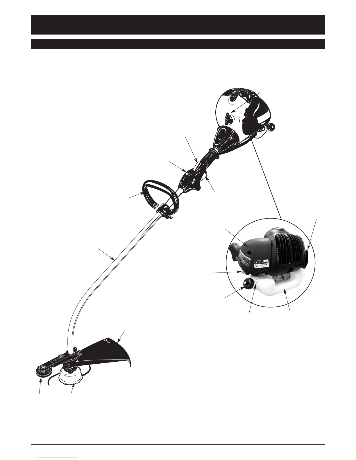
KNOW YOUR UNIT
Choke
Control
Fuel Tank
Fuel
Cap
Muffler
Shield
Air Filter
Cover
Primer
Bulb
Starter Rope
Grip
Throttle
Control
Throttle
Lock-Out
On/Off Stop
Control
Cutting Attachment
Shield
Cutting Attachment
Edging
Guide Wheel
Handle
Shaft
Housing
Page 7
7
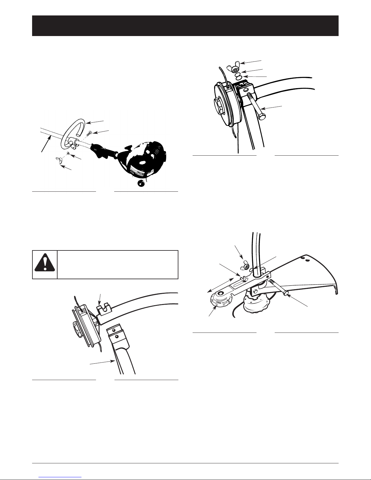
ASSEMBLY INSTRUCTIONS
On some units, the handle may installed, but is turned
down under to help in packaging. In this case you must
adjust the handle to fit the operator.
INSTALL / ADJUST THE HANDLE
1. Place the handle on the drive shaft.
2. Insert the bolt through the handle in secure it with
the washer an wing nut (Fig. 1).
3. Adjust the handle to fit the operator and tighten the
wing nut.
INSTALL THE CUTTING ATTACHMENT SHIELD
NOTE: The cutting attachment shield must be installed
to properly dispense the trimming line.
To install the cutting attachment shield:
1. Place the cutting attachment shield onto the shaft
bracket (Fig. 2).
2. Insert the bolt through the shield, bracket, washer
and lock washer tighten with the wing nut (Fig. 3).
Bracket
Cutting Attachment
Shield
Fig. 3
Never operate the
trimmer without the
cutting attachment shield in place to prevent serious personal injury.
WARNING:
Fig. 4
EDGE GUIDE WHEEL
1. Push edge guide wheel onto the shaft (Fig. 4). Some
force may be required.
Fig. 2
Bolt
Handle
Washer
Wing Nut
Shaft
Fig. 1
Bolt
Lock Washer
Washer
Wing Nut
Bolt
Wing Nut
Depth
Adjustment
Nut
Edge Guide
Wheel
Washer
3. Adjust the edging depth by loosening the depth
adjustment nut. Then move the guide wheel along
the path shown by the arrows to the desired position
(Fig. 4). Tighten securely.
2. Install the bolt, washer and wing nut and tighten
securely.
Page 8
8
OIL AND FUEL INFORMATION
NOTE: Dispose of the old fuel/oil mix in accordance to
Federal, State and Local regulations.
OIL AND FUEL MIXING INSTRUCTIONS
Old and/or improperly mixed fuel are the main reasons
for the unit not running properly. Be sure to use fresh,
clean unleaded fuel. Follow the instructions carefully for
the proper fuel/oil mixture.
Definition of Blended Fuels
Today's fuels are often a blend of gasoline and oxygenates such as ethanol, methanol, or MTBE (ether).
Alcohol-blended fuel absorbs water. As little as 1%
water in the fuel can make fuel and oil separate. It forms
acids when stored. When using alcohol-blended fuel,
use fresh fuel (less than 60 days old).
Using Blended Fuels
If you choose to use a blended fuel, or its use is
unavoidable, follow recommended precautions:
• Always use the fresh fuel mix explained in your operator's manual
• Always agitate the fuel mix before fueling the unit
• Drain the tank and run the engine dry before storing
the unit
Using Fuel Additives
The bottle of 2-cycle oil that came with your unit contains a fuel additive which will help inhibit corrosion and
minimize the formation of gum deposits. It is recommended that you use our 2-cycle oil with this unit.
If unavailable, use a good 2-cycle oil designed for
air-cooled engines along with a fuel additive, such as
STA-BIL®Gas Stabilizer or an equivalent. Add 0.8 oz.
(23 ml.) of fuel additive per gallon of fuel according to
the instructions on the container. NEVER add fuel additives directly to the unit's fuel tank.
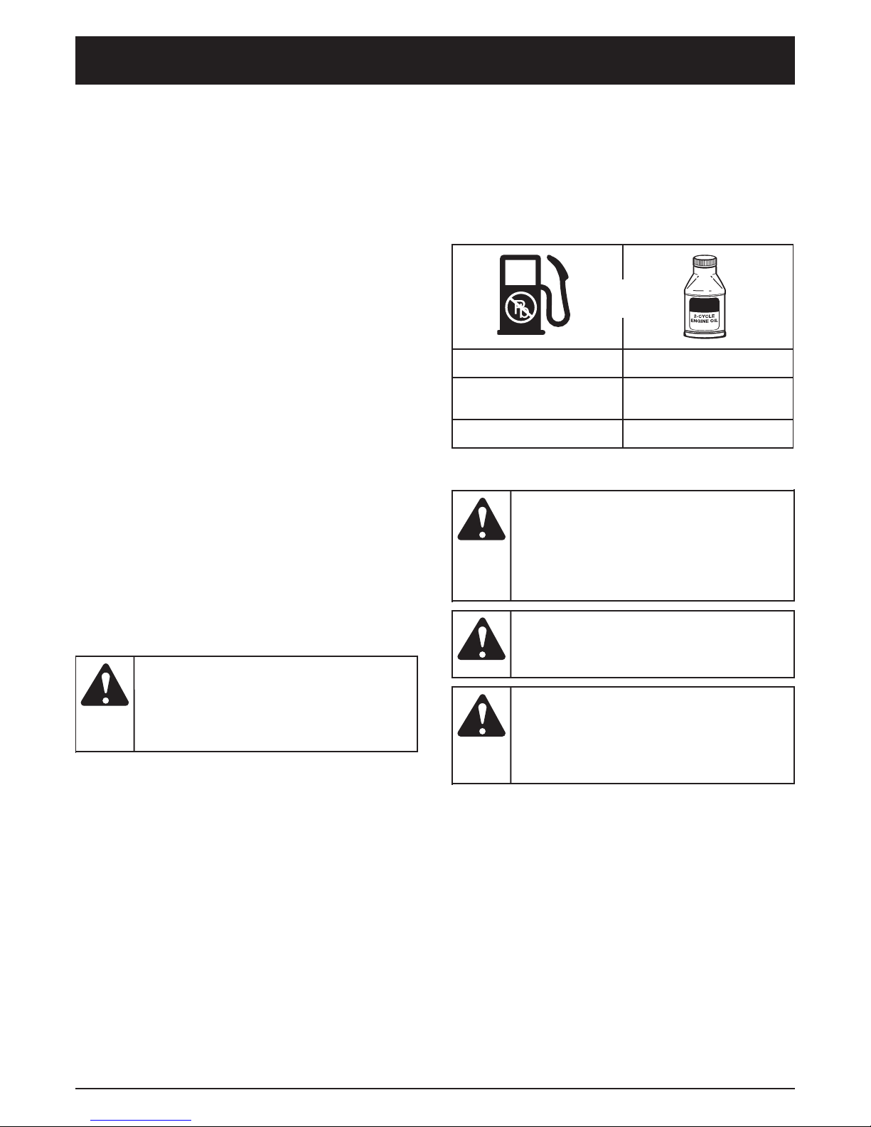
Thoroughly mix the proper ratio of 2-cycle engine oil
with unleaded gasoline in a separate fuel can. Use a
40:1 fuel/oil ratio. Do not mix them directly in the engine
fuel tank. See the table below for specific gas and oil
mixing ratios.
NOTE: One gallon (3.8 liters) of unleaded gasoline
mixed with one 3.2 oz. (95 ml.) bottle of
2-cycle oil makes a 40:1 fuel/oil ratio.
UNLEADED GAS 2 CYCLE OIL
1 GALLON US
(3.8 LITERS)
3.2 FL. OZ.
(95 ml)
1 LITER 25 ml
+
MIXING RATIO - 40:1
Add fuel in a clean,
well ventilated outdoor area. Wipe up any spilled fuel immediately. Avoid creating a source of ignition for
spilt fuel. Do not start the engine until fuel
vapors dissipate.
WARNING:
Gasoline is
extremely flammable. Ignited Vapors may explode. Always
stop the engine and allow it to cool before
filling the fuel tank. Do not smoke while filling the tank. Keep sparks and open flames
at a distance from the area.
WARNING:
Remove fuel cap
slowly to avoid injury
from fuel spray. Never operate the unit without the fuel cap securely in place
.
WARNING:
For proper engine
operation and maximum reliability, pay strict attention to the oil
and fuel mixing instructions on the 2-cycle
oil container. Using improperly mixed fuel
can severely damage the engine.
CAUTION:
NOTE: If your engine is damaged from insufficient lubrica-
tion, it voids the manufacturer’s warranty. Straight
gasoline in the unit also voids the warranty.
Page 9
9
Fig. 6
STARTING A COLD ENGINE
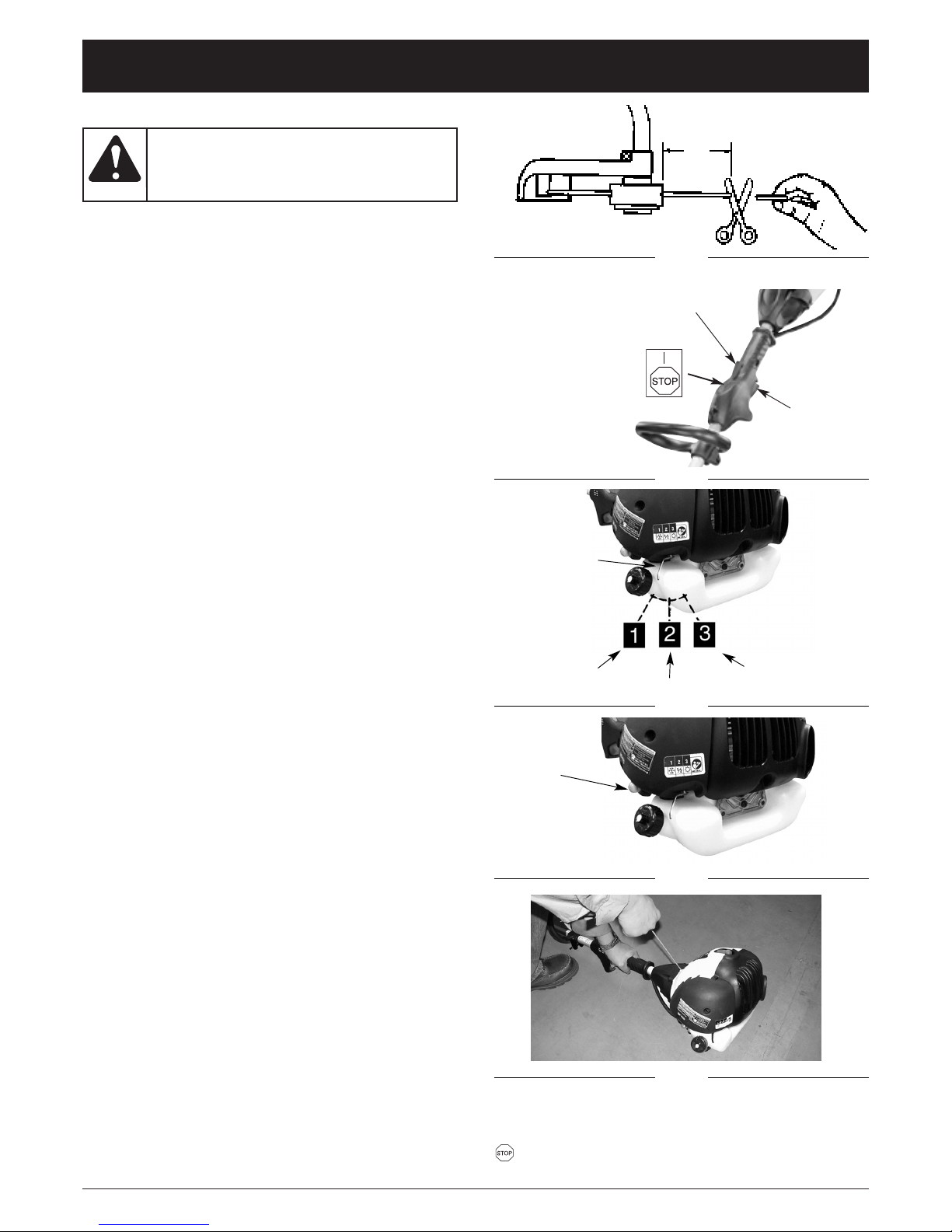
NOTE: To minimize the load on the engine during starting
and warm-up, trim any excess trimming line.
Leave about 5 inches (13 cm) of line from the
cutting attachment (Fig. 5).
1. Mix gas with oil. Fill fuel tank with fuel/oil mixture.
See Oil and Fuel Mixing Instructions.
2. Move the ignition switch to the Run position (Fig. 6).
3. Move choke lever to Position 1 (Fig. 7).
4. Prime the carburetor by fully pressing and releasing
the primer bulb 10 times (Fig. 8).
5. Grip the handle firmly and press the safety trigger
and press/squeeze the throttle trigger to the Full
Throttle position (Fig. 6).
6. Pull the starter rope out a short way until you feel
resistance (approximately 4”). Then continue with a
smooth rapid pull (for a strong spark). Pull the rope
briskly in this manner 4 times (Fig. 9).
7. Move the choke lever to Position 2.
8. With the throttle trigger still in the Full Throttle
position, pull the starter rope 4 more times.
9. When the engine starts, leave the choke lever in
Position 2 for about 10 seconds, so the unit can
warm up.
10. Move the choke lever to Position 3. The trimmer is
ready for use.
If engine fails to start, repeat everything from Step 2 on.
NOTE: Always pull the starter rope straight out. If you pull it
at an angle, the rope will rub against the eyelet. This
friction may cause the rope to fray a wear more
quickly . Always hold the starter handle when the
rope retracts. Never allow the rope to snap back
from an extended position. This could damage the
starter assembly or cause the rope to snag.
NOTE: Idling Information: in some cases due to
operating conditions (extreme altitude,
temperature, etc.), your unit may need a slight
adjustment to its idle speed. If your unit does not
idle after restarting two times, refer to Adjusting
the Idle Speed.
STARTING A WARM ENGINE
1. Move the ignition switch to the Run position (Fig. 6).
2. Move choke lever to Position 1 (Fig. 7).
3. Grip the handle firmly and press/hold the safety
trigger. Then press the throttle trigger to the Full
Throttle position (Fig. 6).
4. Pull the starter rope briskly until the engine starts. Do
NOT pull it more than 6 TIMES. Keep the throttle
trigger at the Full Throttle position until the engine
runs smoothly.
NOTE: If the engine doesn’t start, place the choke in
Position 3 and pull the starter rope 5 times. If the
engine doesn’t then start, the engine is probably
flooded. Wait 5 minutes and then repeat the
procedure with the choke in Position 3 and the
throttle trigger in Full Throttle.
Fig. 5
5 in.
(13 cm)
Fig. 7
Throttle
Trigger
Safety Trigger
Fig. 8
STARTING/STOPPING INSTRUCTIONS
Ignition
Switch
Fig. 9
Operate this unit only
in a well- ventilated
outdoor area. Carbon monoxide exhaust fumes
can be lethal in a confined area.
WARNING:
STOPPING ENGINE
To stop the unit, first release the throttle trigger. Let the
engine return to idle. Move ignition switch to the "STOP
" position for stopping engine.
Choke
Lever
Position 1
Position 2
Position 3
Primer
Bulb
Page 10
10
OPERATING INSTRUCTIONS
Fig. 10
Fig. 11
DO NOT use steel
wire or plasticcoated steel wire of any kind with your
stringhead. Serious operator injury can result.
WARNING:
Periodically remove
wrapped weeds to
prevent overheating the drive shaft. W eed
wrap occurs when strands of weeds become
entangled around the shaft beneath the
debris shield (Fig. 11). This condition prevents
the shaft from cooling properly. Remove weed
wrap with a screwdriver or a similar device.
CAUTION:
ADJUSTING TRIMMING LINE LENGTH
To release fresh line, run engine at full throttle and
“bump” stringhead against lawn. Line will automatically
release. The blade in debris shield will trim excess line
(Fig. 10).
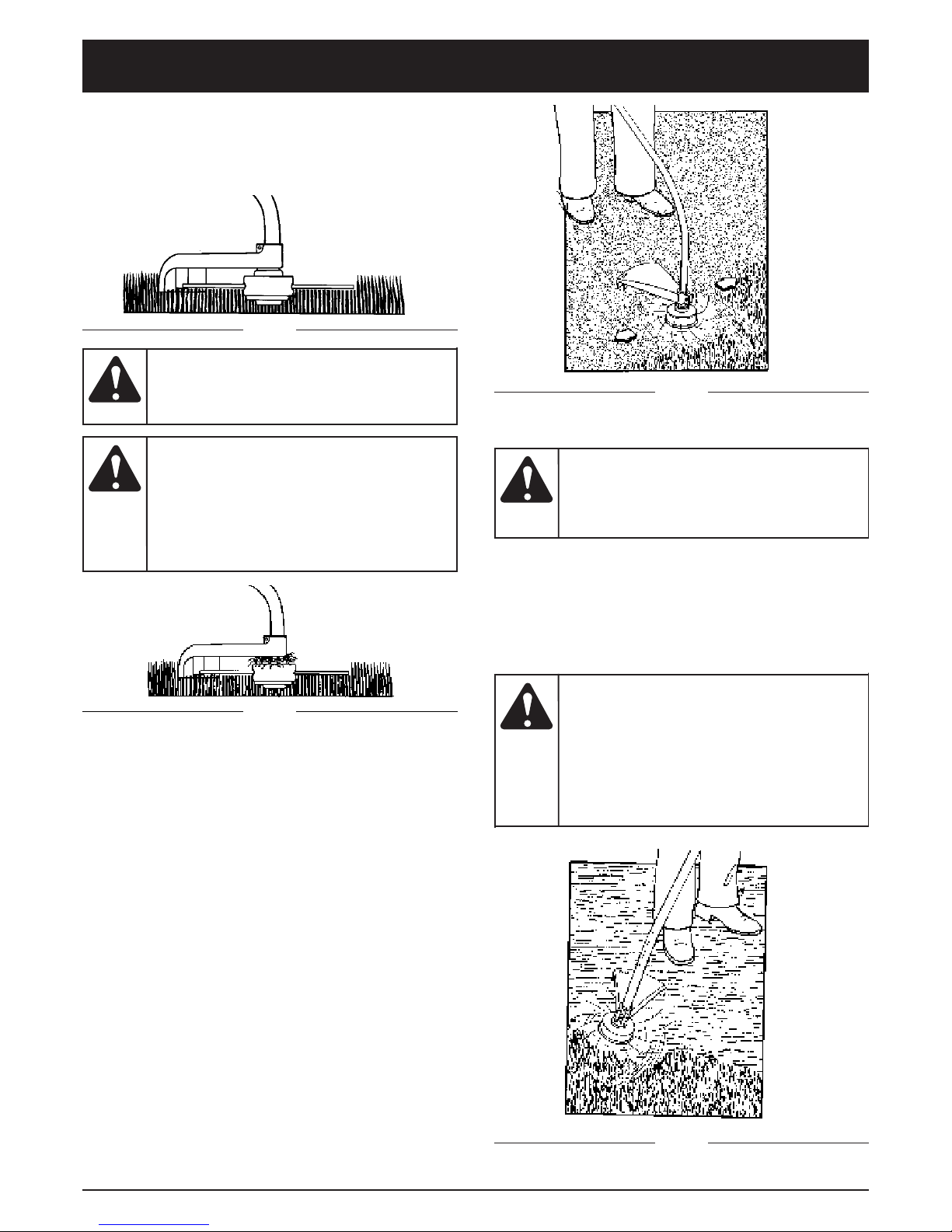
TRIMMING PROCEDURES
NOTE: Even with care, trimming around foundations,
brick or stone walls, curves, etc., will result in
above normal string wear.
Trimming / Mowing
Swing trimmer with a sickle-like motion from side to
side. Do not tilt the stringhead during the procedure.
Test area to be trimmed for proper cutting height. Keep
stringhead at same level for even depth of cut (Fig. 12).
Closer Trimming
Position trimmer straight ahead with a slight tilt so
bottom of stringhead is above ground level and string
contact occurs at proper cutting point. Always cut away
from operator. Do not pull trimmer in toward operator.
Fence / Foundation Trimming
Approach trimming around chain link fences, picket
fences, rock walls and foundations slowly to cut close
without whipping string against the barrier. If the string
comes in contact with rock, brick walls, or foundations,
it will break or fray. If string snags fencing, it will snap off.
Trimming Around Trees
Trim around tree trunks with a slow approach so string
does not contact bark. Walk around the tree trimming
from left to right. Approach grass or weeds with the tip
of the string and tilt stringhead slightly forward.
Fig. 12
Scalping
Scalping refers to removal of all vegetation down to the
ground. To do this, tilt the stringhead to about a 30
degree angle to the left. By adjusting the handle you will
have better control during this operation. Do not attempt
this procedure if there is any chance flying debris could
injure operator, other people or cause damage to
property.
DO NOT sweep
with trimmer.
Sweeping refers to tilting stringhead to
sweep away debris from walkways, etc.
Your trimmer is a powerful tool and small
stones or other such debris may be hurled
50 feet (15 m) or more, causing injury or
damage to nearby property such as
automobiles, homes and windows.
WARNING:
Use extreme
caution when
scalping. Keep a distance of 100 feet (30 m)
between operator, other people and
animals during these operations.
WARNING:
Fig. 13
Page 11
11
MAINTENANCE AND REPAIR INSTRUCTIONS
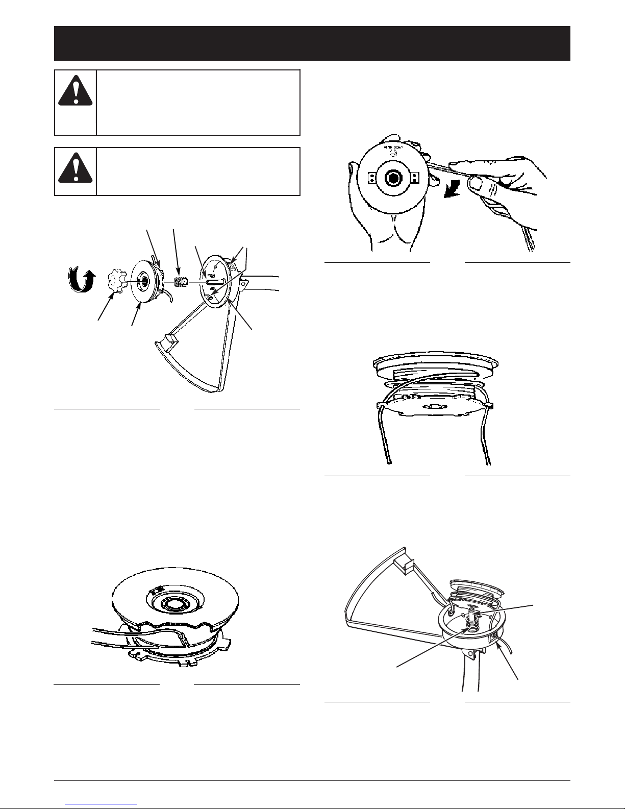
REPLACING TRIMMING LINE
1. Turn the knob counterclockwise to remove it (Fig. 14).
2. Remove the spool and the spring from the spindle.
3. Remove any remaining trimming line.
4. Cut a 14’ (4.3 m) length of replacement trimming line.
Double it over, using 0.095 in (2.43 mm) trimming line.
Place the looped center in one of the slots in the
spool divider (Fig. 15).
Knob
Slots
Spring
Spindle
Eyelets
Housing
Spool
Fig. 14
Fig. 15
Fig. 16
5. Wind the trimming line clockwise (Fig. 16). Keep
tension on the line, and make sure each half of line is
separated by the spool divider. Continue winding
until the line is within 6 inches (15 cm) of the ends.
To prevent serious
injury, never perform maintenance or repairs with unit running. Always service and repair a cool unit.
Disconnect the spark plug wire to ensure
that the unit cannot start.
WARNING:
Never use metal-
reinforced line, wire,
chain or rope. These can break off and
become dangerous projectiles.
WARNING:
6. Lock each end of the line into a slot on opposite
sides of the spool (Fig. 17).
7. Install the spring over the spindle. Insert each end of
the line through an eyelet in the housing (Fig. 14).
Fig. 17
Fig. 18
Slots
Spring
Eyelet
8. Lower the spool onto the housing while feeding the
line through the eyelets. Ensure that the spring seats
itself into the spool (Fig. 18).
Spindle
Page 12

12
MAINTENANCE AND REPAIR INSTRUCTIONS
Fig. 20
Fig. 19
Cutting
Line Ends
9. Once the spool is in place, apply pressure on the
spool that is compressing the spring. Pull each end
of the line sharply to unlock the line from the slots
(Fig. 19).
10. Continue to apply pressure to the spool until the
knob can be threaded clockwise onto the spindle.
Tighten the knob securely by hand (do not use any
other instrument) (Fig. 20).
11. Trim the excess line to about 5 in (13 cm). This will
minimize the load on the engine when it starts and
warms up.
Fig. 21
Fig. 22
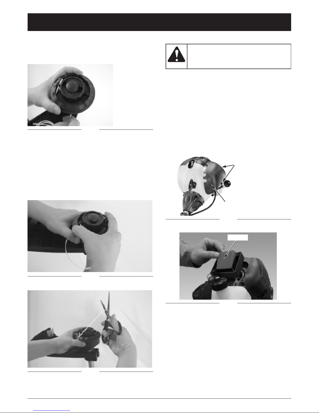
REPLACING TRIMMING LINE: EASY-LOAD
HEAD
1. Use a small screwdriver or pointed rod to release line
from the locking tabs (Fig. 21).
2. Remove remaining line from head.
3. Align arrows on inner and outer spool (Fig. 22).
4. Cut a length of trimming line approximately 16 feet (5
meters) long.
5. While pushing inner spool down insert each end of
line through eyelets into feed slot on spool divider.
Ensure line enters feed slots. Push line until
approximately 2 inches (5 cm) appears from below
bump knob (Fig. 23).
Fig. 23
Page 13
13
MAINTENANCE AND REPAIR INSTRUCTIONS
Fig. 26
Fig. 25
Fig. 24
6. Insert each end into locking tabs by pushing the line
end through lower tab hole and looping end back
through upper tab hole. Pull line at eyelet to tension
(Fig. 24).
7. Once both line ends are locked in place turn inner
spool counter clockwise in direction of arrows to
load line (Fig. 25).
8. Wind spool until a loop of line approximately 10
inches (25cm) long is visible. Cut loop in half to
create two cutting line ends (Fig. 26). Ensure each
line end is not more than 5 inches (13cm) long. This
will minimize load on engine during starting.
AIR FILTER
To clean the air filter:
1. Remove the 2 screws holding air filter cover in place
(Fig. 27).
2. Remove the cover and lift the filter from the air box
(Fig. 28).
3. Wash the air filter in soap and water. DO NOT USE
GASOLINE!
4. Air dry filter.
5. Reinstall the filter, cover and screws.
NOTE: Replace filter if frayed, torn, damaged or unable
to be cleaned.
Never operate the
unit without the air
filter. The air filter must be kept clean. If it
becomes damaged, install a new filter
CAUTION:
Fig. 27
Fig. 28
Screws
Cover
Air Filter
Page 14
14
MAINTENANCE AND REPAIR INSTRUCTIONS
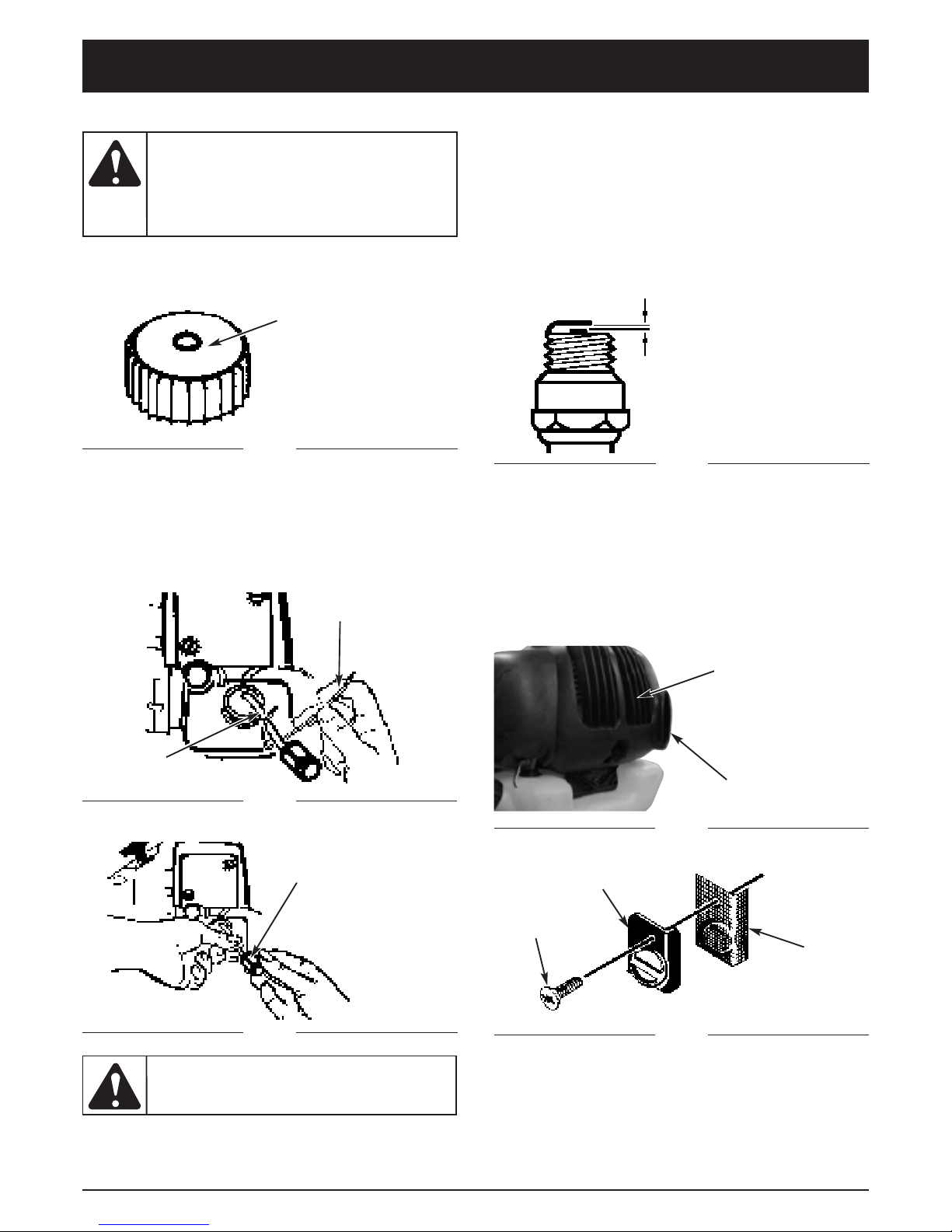
FUEL CAP AND FUEL FILTER
NOTE: Be sure to keep the vent on the fuel cap free of
debris (Fig. 29).
Remove all fuel from
the unit and store in
an approved container before starting this
procedure. Open the fuel cap slowly to
release any pressure which may have
formed in the fuel tank.
CAUTION:
Never operate the
unit without the fuel
filter. Internal engine damage could result.
CAUTION:
To clean the fuel filter:
1. Lift the fuel line and filter out of the tank. Use a steel
wire with a hook or a paper clip (Fig. 30).
2. Pull the filter off with a twisting motion (Fig. 31).
3. Replace the fuel filter.
Fig. 29
Fuel Cap
Vent
Fig. 31
Steel Wire
Fuel Line
and Filter
Fig. 30
Fuel Filter
CARBURETOR ADJUSTMENT
The carburetor was pre-set at the factory for optimum
performance. If further adjustments are necessary,
please take your unit to the nearest authorized service
center.
SPARK PLUG
Set the spark plug gap to 0.025" (0.635 mm) (Fig. 32).
Torque to 105 to 130 inch pounds (12 to 15 N•m).
Connect the spark plug boot.
Fig. 32
0.025” (0.635 mm)
Fig. 33
Muffler
Shield
Spark Arrestor
Location
Fig. 34
Screen
Cover
Retaining
Screw
Spark
Arrestor
Screen
SPARK ARRESTER SCREEN
NOTE: It is not necessary to take the muffler shield off
to replace or install a new spark arrester screen
(Fig. 33).
To replace the spark arrester screen, remove the single
retaining screw and screen cover. Discard old screen.
Install new screen (Fig. 34).
Page 15

15
IDLE SPEED ADJUSTMENT
1. Locate the idle adjustment screw on the carburetor
(Fig. 36).
2. Using a screwdriver, turn the screw 1/4 to 1/2 of a
turn clockwise (to the right). The unit should then idle
properly.
Idle Adjustment
Screw
MAINTENANCE AND REPAIR INSTRUCTIONS
Fig. 35
Debris
Shield
Line Cutting
Blade
SHARPENING THE LINE CUTTING BLADE
1. Remove the line cutting blade from the debris shield
(Fig. 35).
2. Place the blade in a bench vise. Sharpen the blade
using a flat file, being careful to maintain the angle of
cutting edge. File in one direction only.
Fig. 36
STORING A UNIT
1. Perform all the general maintenance recommended in
the Maintenance Section of your operator’ s manual.
2. Clean the exterior of the engine, drive shaft
assembly, debris shield and stringhead.
4. After fuel is drained, start engine.
5. Run engine at idle until unit stops. This will purge the
carburetor of fuel.
6. Allow the engine to cool (approx. 5 minutes).
7. Using a spark plug wrench, remove the spark plug.
8. Pour 1 teaspoon of clean 2-cycle oil into the
combustion chamber. Pull the starter rope slowly
several times to coat internal components. Replace
the spark plug.
9. Store the unit in a cool, dry place away from any source
of ignition such as an oil burner , water heater, etc.
REMOVING A UNIT FROM STORAGE
1. Remove spark plug.
2. Pull starter rope briskly to clear excess oil from
combustion chamber.
3. Clean and gap spark plug or install a new spark plug
with proper gap.
4. Prepare unit for operation.
5. Fill fuel tank with proper fuel / oil mixture. Refer to
the Oil and Fuel Information section.
Failure to follow
these steps may
cause varnish to form in the carburetor; this
may result in difficulty when starting or
permanent damage following storage. This
may void your warranty
WARNING:
Page 16

16
If further assistance is required, contact your authorized service dealer.
CAUSE ACTION
Cutting attachment bound with grass Stop the engine and clean cutting attachment
Cutting attachment out of line Refill with new line
Cutting head dirty Clean inner reel and outer spool
Line twisted when refilled Disassemble and rewind the line
CAUSE ACTION
Incorrect spark plug gap Adjust gap to 0.025” (0.635 mm) or clean/replace plug
CAUSE ACTION
Empty fuel tank Fill fuel tank with properly mixed fuel
Incorrect starting procedure Follow starting instructions shown in operator’s manual
Old or improperly mixed fuel Drain gas tank and add fresh fuel mixture
Fouled spark plug Replace or clean the spark plug
Plugged spark arrestor Clean or replace spark arrestor
Plugged fuel filter Replace fuel filter
ENGINE WILL NOT START OR STARTS BUT WILL NOT RUN
UNIT STARTS, BUT ENGINE HAS LOW POWER
ENGINE HESITATES
ENGINE RUNS ERRATICALLY
CAUSE ACTION
Air filter is plugged Replace or clean the air filter
Old or improperly mixed fuel Drain gas tank and add fresh fuel mixture
Improper carburetor adjustment Adjust according to the Carburetor Adjustments section
Choke lever is in incorrect position Move choke lever to Position 3
CAUSE ACTION
Improper carburetor adjustment Take to an authorized service dealer for an adjustment
CUTTING ATTACHMENT WILL NOT ADVANCE LINE
TROUBLESHOOTING
NO POWER UNDER LOAD
CAUSE ACTION
Improper carburetor adjustment Take to an authorized service dealer for an adjustment
CAUSE ACTION
Improper carburetor mixture/adjustment Take to an authorized service dealer for an adjustment
Old or improperly mixed fuel Drain gas tank and add fresh fuel mixture
UNIT SMOKES EXCESSIVELY
CAUSE ACTION
Weed wrap Remove weed wrap
CUTTING ATTACHMENT AND SHAFT ARE HOT TO THE TOUCH
Page 17

17
SPECIFICATIONS
ENGINE*
DRIVE SHAFT and CUTTING ATTACHMENT*
Engine Type .......................................................................................................................................... Air-Cooled, 2-Cycle
Displacement .......................................................................................................................................... 1.95 cu in. (32 cc)
Ignition Type .......................................................................................................................................................... Electronic
Spark Plug Gap ................................................................................................................................. 0.025 in. (0.635 mm.)
Lubrication................................................................................................................................................... Fuel/Oil Mixture
Fuel/Oil Ratio................................................................................................................................................................ 40:1
Carburetor..................................................................................................................................... Primer / Diaphragm Type
Drive.................................................................................................................................................................. Direct Driver
Fuel Tank Capacity............................................................................................................................. 23.3 fl.oz. (689.7 ml.)
Drive Shaft Length ....................................................................................................................................... 48 in. (122 cm)
Handle...............................................................................................................................................................Open Handle
Approximate Unit Weight (No fuel) .......................................................................................................... 11.2 lbs. (5.1 kg.)
Trimming Line Diameter....................................................................................................................... 0.080 in. (2.03 mm.)
Cutting Path Diameter............................................................................................................................. 17 in. (43.18 cm.)
*All specifications are based on the latest product information available at the time of printing. We reserve the right to
make changes at any time without notice.
Page 18

MANUFACTURER’S LIMITED WARRANTY FOR:
No implied warranty, including any implied warranty of
merchantability or fitness for a particular purpose,
applies after the applicable period of express written
warranty above as to the parts as identified. No other
express warranty or guaranty, whether written or oral,
except as mentioned above, given by any person or
entity, including a dealer or retailer, with respect to any
product shall bind MTD. During the period of the
Warranty, the exclusive remedy is repair or replacement
of the product as set forth above.
(Some states do not
allow limitations on how long an implied warranty lasts, so
the above limitation may not apply to you.)
The provisions as set forth in this Warranty provide the
sole and exclusive remedy arising from the sales. MTD
shall not be liable for incidental or consequential loss or
damages including, without limitation, expenses
incurred for substitute or replacement lawn care
services, for transportation or for related expenses, or
for rental expenses to temporarily replace a warranted
product.
(Some states do not allow limitations on how long
an implied warranty lasts, so the above limitation may not
apply to you.)
In no event shall recovery of any kind be greater than the
amount of the purchase price of the product sold. Alteration
of the safety features of the product shall void this Warranty.
You assume the risk and liability for loss, damage, or injury
to you and your property and/or to others and their property
arising out of the use or misuse or inability to use the
product.
This limited warranty shall not extend to anyone other than
the original purchaser, original lessee or the person for
whom it was purchased as a gift.
How State Law Relates to this Warranty: This warranty
gives you specific legal rights, and you may also have other
rights which vary from state to state.
To locate your nearest service dealer dial 1-800-345-8746 in
the United States or 1-800-668-1238 in Canada.
MTD LLC
P.O. Box 361131
Cleveland, OH 44136-0019
The limited warranty set forth below is given by MTD
LLC (“MTD”) with respect to new merchandise purchased and
used in the United States, its possessions and territories.
MTD warrants this product against defects in material and
workmanship for a period of two (2) years commencing on the
date of original purchase and will, at its option, repair or
replace, free of charge, any part found to be defective in
material or workmanship. This limited warranty shall only apply
if this product has been operated and maintained in
accordance with the Operator’s Manual furnished with the
product, and has not been subject to misuse, abuse,
commercial use, neglect, accident, improper maintenance,
alteration, vandalism, theft, fire, water or damage because of
other peril or natural disaster. Damage resulting from the
installation or use of any accessory or attachment not
approved by MTD for use with the product(s) covered by this
manual will void your warranty as to any resulting damage. This
warranty is limited to ninety (90) days from the date of original
retail purchase for any MTD product that is used for rental or
commercial purposes, or any other inco me-p r oduci ng purpose.
HOW TO OBTAIN SERVICE: Warranty service is available,
WITH PROOF OF PURCHASE THROUGH YOUR LOCAL
AUTHORIZED SERVICE DEALER. To locate the dealer in your
area, please check for a listing in the Yellow Pages or contact
the Customer Service Department of MTD LLC by calling
1-800-345-8746 or writing to P.O. B ox 3 61 1 31 , Cl ev el an d O H
44136 -0019 or if in Canada call 1-800-668-1238. No product
returned directly to the factory will be accepted unless prior
written permission has been extended by the Customer
Service Department of MTD LLC.
This limited warranty does not provide coverage in the
following cases:
A. Tune-ups - Spark Plugs, Carburetor Adjustments, Filters.
B. Wear items - Bump Knobs, Outer Spools, Cutting Line,
Inner Reels, Starter Pulley, Starter Ropes, Drive Belts.
C. MTD does not extend any warranty for products sold or
exported outside of the United States of America, its
possessions and territories, except those sold through
MTD’s authorized channels of export distribution.
MTD reserves the right to change or improve the design of
any MTD Product without assuming any obligation to modify
any product previously manufactured.
Page 19

IMPORTANT: LISEZ LES RÈGLES ET
CONSIGNES DE SÉCURITÉ SOIGNEUSEMENT
P/N 9096-333606 © 2004
FABRIQUÉ Á CHINA
Désherbeuse à gaz
MCT33360E
Manuel de l'utilisateur
Français
Page 20

F2
Copiez le numéro
de série ici :
Copiez le numéro de
modèle / pièce mère ici :
TOUS NOS REMERCIEMENTS
Nous vous remercions d'avoir acheté ce produit de
qualité. Cet outil mécanique de plein air moderne est
conçu pour vous rendre service pendant longtemps. Il
vous sauvera beaucoup de temps comme vous pourrez
vous en rendre compte. Ce manuel de l'utilisateur
comporte un mode d'emploi facile à comprendre. Prenez
soin de lire le manuel au complet et suivez toutes ses
instructions à la lettre afin de conserver votre nouvel outil
mécanique de plein air en excellent état de
fonctionnement.
RÉFÉRENCES, ILLUSTRATIONS ET
SPÉCIFICATIONS RELATIVES AU PRODUIT
Toutes les informations, illustrations et spécifications
contenues dans ce manuel tiennent compte des
dernières informations techniques disponibles au
moment de mettre sous presse. Nous nous réservons le
droit d'y apporter des modifications à tout moment, sans
préavis.
Copyright© 2004 MTD SOUTHWEST INC., Tous droits
réservés.
NFORMATIONS D’ENTRETIEN
Tout entretien effectué sur cet appareil pendant et après
la période de garantie doit être fait par un concessionnaire agréé uniquement. Obtenez la liste des
concessionnaires agréés appelez le 1-800-345-8746
aux
États-unis, ou le
1-800-668-1238
au Canada
. Pour de
plus amples informations à propos de votre appareil,
visitez www.yardmachines.com.
NE RETOURNEZ PAS L'APPAREIL AU DÉTAILLANT
CHEZ QUI VOUS L'AVEZ ACHETÉ. TOUT SERVICE
SOUS GARANTIE NÉCESSITE UNE PREUVE D'ACHAT.
Avant d'assembler votre nouvel équipement, repérez la
plaque signalétique de l'appareil et copiez ses
informations dans l'espace ci-dessous. Ces informations
sont essentielles si vous désirez obtenir de l'aide auprès
de notre service technique ou d'un distributeur agréé. Un
exemple de plaque signalétique est présenté ci-dessous.
S/N :
ITEM :
MODEL :
TABLE DES MATIÈRES
Introduction . . . . . . . . . . . . . . . . . . . . . . . . . . . . . . . .2
Consignes de sécurité . . . . . . . . . . . . . . . . . . . . . . .3
Familiarisez-vous avec votre appareil . . . . . . . . . . . .6
Instructions de montage . . . . . . . . . . . . . . . . . . . . . .7
Informations sur l'huile et le carburant . . . . . . . . . . .8
Instructions de démarrage et d'arrêt . . . . . . . . . . . .9
Mode d'emploi . . . . . . . . . . . . . . . . . . . . . . . . . . . .10
Entretien et réparations . . . . . . . . . . . . . . . . . . . . . .11
Tableau de dépannage . . . . . . . . . . . . . . . . . . . . . .16
Caractéristiques . . . . . . . . . . . . . . . . . . . . . . . . . . .17
Garantie . . . . . . . . . . . . . . . . . . . . . . . . . . . . . . . . . .18
Liste des piè c e s . . . .Intérieure de la Couverture Arrière
Numéro de modèle
Numéro de série
Numéro de pièce mère
Si vous éprouvez des difficultés à assembler ce produit
ou si vous avez des questions concernant les
commandes, le fonctionnement ou l’entretien de cet
appareil, veuillez communiquer avec notre service
technique.
INTRODUCTION
PARE-ÉTINCELLES
REMARQUE : à l'intention des utilisateurs opérant
dans les terres forestières des États-Unis et dans les
états de Californie, du Maine, de l'Orégon et de
Washington. Toutes les terres forestières des États-Unis et
de l'état de Californie (Codes sur les ressources publiques
4442 et 4443), de l'Orégon et de Washington exigent de
par la loi que certains moteurs à combustion interne utilisés dans des zones couvertes de taillis ou d'herbe soient
équipés d'un pare-étincelles en parfait état de fonctionnement, ou qu'ils soient conçus, équipés et entretenus
pour la prévention des incendies. Renseignez-vous auprès
des autorités de votre province ou de votre municipalité
concernant la réglementation en vigueur. Vous pourriez
être passible d'une amende ou être tenu responsable si
vous ne respectez pas cette réglementation. Cet appareil
est équipé d'un pare-étincelles en usine. Si l'écran pare-
étincelles, réf. 182747, doit être remplacé, communiquez avec le service technique.
AVERTISSEMENT
LES GAZ D'ÉCHAPPEMENT DU MOTEUR DE
CET APPAREIL CONTIENNENT DES PRODUITS
CHIMIQUES CONSIDÉRÉS PAR L'ÉTAT DE CALI-
FORNIE COMME POUVANT CAUSER LE CAN-
CER, DES MALFORMATIONS CONGÉNITALES
OU D'AUTRES EFFETS NOCIFS SUR L'AP-
PAREIL DE REPRODUCTION.
AVERTISSEMENT DE LA PROPOSITION 65 DE
CALIFORNIE
Prenez soin de lire et de bien comprendre ce manuel avant de démarrer ou de faire fonctionner cet équipement.
CE PRODUIT EST COUVERT PAR UN OU PLUSIEURS BREVETS AMÉRICAINS, ET D’AUTRES SONT EN INSTANCE.
Page 21

F3
SYMBOLE SIGNIFICATION
SYMBOLE SIGNIFICATION
Les symboles de sécurité attirent votre attention sur
des dangers potentiels. Ces symboles et leurs détails
explicatifs méritent que vous les lisiez et compreniez
bien. Les avertissements de sécurité ne peuvent éviter
les dangers de par eux-mêmes. Les consignes ou
mises en garde qu'ils donnent ne remplacent pas des
mesures préventives appropriées contre les accidents.
REMARQUE: donne des informations ou des
instructions vitales pour le fonctionnement ou
l'entretien de l'équipement.
le non-
respect d’un
avertissement peut causer dommages matériels
ou blessures graves pour tous. Respectez les
consignes de sécurité afin de réduire les risques
d'incendie, d'électrocution et de blessures.
AVERTISSEMENT :
le non-respect d’un
avertissement peut
causer dommages matériels ou blessures
graves pour tous. Respectez les consignes de
sécurité afin de réduire les risques d'incendie,
d'électrocution et de blessures.
DANGER:
le non-
respect
d’un avertissement peut causer dommages
matériels ou blessures graves pour tous.
Respectez toujours les consignes de sécurité
afin de réduire les risques d'incendie,
d'électrocution et de blessures.
MISE EN GARDE:
indique un danger, un avertissement ou une
mise en garde. Soyez vigilant afin d'éviter toute
blessure grave. Ce symbole peut être combiné
à d'autres symboles ou pictogrammes.
ALERTE DE SÉCURITÉ:
Lisez le(s) manuel(s) de l'utilisateur et suivez tous
les avertissements et consignes de sécurité. Vous
pourriez à défaut entraîner des blessures graves
pour vous ou d'autres personnes.
SI VOUS AVEZ DES QUESTIONS, APPELEZ LE 1-800-345-
8746 AUX ÉTATS-UNIS, OU LE 1-800-668-1238 AU CANADA
• IMPORTANTES CONSIGNES DE SÉCURITÉ •
CONSIGNES DE SÉCURITÉ
LIRE TOUTES LES INSTRUCTIONS
AVANT UTILISATION
• Veuillez lire les instructions avec soin. Familiarisezvous avec les commandes et l'utilisation correcte de
cet appareil.
• N'utilisez pas l'appareil si vous êtes fatigué, malade ou
sous l'effet de l'alcool, de drogues ou de médicaments.
• Les enfants et adolescents de moins de 15 ans ne
doivent pas utiliser l'appareil exceptés les adolescents
assistés d'un adulte.
• Inspectez l'appareil avant utilisation. Remplacez les
pièces endommagées. Regardez s'il y a des fuites de
carburant. Assurez-vous que les fixations sont solidement en place. Remplacez les pièces de l'accessoire de
coupe qui sont fendillées, ébréchées ou endommagées.
Assurez-vous que l'accessoire de coupe est correctement installé et solidement fixé. Assurez-vous que le
protecteur d'accessoire de coupe est correctement fixé
et positionné comme recommandé. Vous risquez sinon
de causer des blessures à l'opérateur et aux spectateurs, et d'endommager l'appareil.
• N'utilisez que du fil de remplacement d’ori gi n e d u f ab rican de 2,41mm (0,095 po) de diamètre. N'utilisez
jamais de fil ou de cordon à renfort métallique car ils
peuvent se briser et se transformer en projectile dangereux.
• Soyez conscient des risques de blessure à la tête, aux
mains et aux pieds.
• Dégagez la zone de coupe avant chaque usage. Enlevez
tous les objets pouvant être projetés ou happés par l'accessoire de coupe : cailloux, verre brisé, clous, fil ou
ficelle. Éloignez enfants, spectateurs et animaux de la
zone de coupe. Tenez-les à au moins 15 m (50 pi) de là
mais sachez que les spectateurs risquent quand même
d'être atteints par des objets projetés. Conseillez-leur de
porter des protecteurs oculaires. Arrêtez immédiatement
le moteur et l'accessoire de coupe si quelqu'un s'approche de vous.
• Appuyez sur la manette des gaz et assurez-vous
qu'elle revient automatiquement en position de ralenti.
Procédez à tous les réglages ou réparations avant
d'utiliser l'appareil.
• Cet appareil n'est pas conçu pour servir de débroussailleuse. N'utilisez cet appareil avec aucun type de
lame ou d'accessoire de débroussaillage.
AVERTISSEMENTS DE SÉCURITÉ CONCERNANT LES DÉSHERBEUSES À GAZ
• Ne stockez le carburant que dans des contenants
spécialement conçus et homologués pour le stockage
de ce type de matières.
• Évitez de créer une source d'allumage pour le carburant déversé. Ne démarrez pas le moteur avant que
les vapeurs de carburant ne se soient dissipées.
suivez
soigneusement les consignes de sécurité lorsque
vous utilisez cet appareil. Dans l'intérêt de votre
sécurité et de celle des personnes à proximité,
prenez soin de lire ces instructions avant de faire
fonctionner la machine. Veuillez garder les
instructions en lieu sûr pour usage ultérieur.
A VERTISSEMENT:
l'essence
est
extrêmement inflammable et ses vapeurs
peuvent exploser si on y met le feu.
Veuillez prendre les précautions suivantes.
AVERTISSEMENT :
Page 22

F4
CONSIGNES DE SÉCURITÉ
• Arrêtez toujours le moteur et laissez-le refroidir avant
de remplir le réservoir de carburant. N'enlevez jamais
le bouchon du réservoir et n'ajoutez jamais de carburant pendant que le moteur est chaud. Ne faites
jamais fonctionner l'appareil sans que le bouchon de
carburant soit bien mis. Desserrez lentement le bouchon afin de réduire la pression du réservoir.
• Mélangez et ajoutez le carburant dans un endroit bien
aéré et propre en plein air à l'abri des étincelles ou
des flammes. N'enlevez lentement le bouchon du
réservoir d'essence qu'après avoir arrêté le moteur.
Ne fumez pas pendant le remplissage ou le mélange
de carburant. Essuyez immédiatement tout déversement de carburant de l'appareil.
•
Éloignez l'appareil d'au moins 9.1 m (30 pi) de la source
de ravitaillement en carburant avant de démarrer le
moteur. Ne fumez pas et éloignez toute source d'étincelles
ou de flammes vives du lieu de ravitaillement ou de fonctionnement de l'appareil.
PENDANT L'UTILISATION DE L'APPAREIL
• Évitez de démarrer ou de faire marcher l'appareil à
l'intérieur d'une pièce ou d'un bâtiment fermé. La respiration de fumées d'échappement peut tuer. Ne
faites fonctionner cet appareil qu'à l'extérieur dans un
endroit bien aéré.
• Portez des lunettes de sécurité conformes aux
normes ANSI Z87.1-1989 ainsi que des protègeoreilles durant l'utilisation de l'appareil. Portez un
masque facial ou antipoussières si vous travaillez
dans un lieu poussiéreux. Il est recommandé de
porter des chemises à manches longues.
• Portez des pantalons épais et longs, des bottes et des
gants. Ne marchez pas pieds nus et ne portez pas les
articles suivants : vêtements lâches, bijoux, pantalons
courts, sandales. Relevez les cheveux au-dessus du
niveau des épaules.
• Le protecteur d'accessoire de coupe doit toujours
être en place lors de l'utilisation de l'appareil. Ne
faites pas marcher l'appareil sans que les deux fils
soient bien déployés, en supposant qu'un fil approprié a été installé. Assurez-vous que le fil ne dépasse
pas le protecteur de sécurité.
• Ajustez la poignée selon votre taille pour mieux l'agripper.
• N'utilisez l'appareil qu'en plein jour ou avec un bon
éclairage artificiel.
• Évitez tout démarrage accidentel. Mettez-vous en position de démarrage chaque fois que vous tirez sur la
corde de démarrage. L'opérateur et l'appareil doivent
tous deux être en position stable à ce moment-là. Voir
les Instructions de démarrage et d'arrêt.
• Ne vous étirez pas. Tenez-vous toujours bien sur vos
pieds en position d'équilibre.
• Tenez toujours l'appareil des deux mains lorsque vous le
faites marcher. Agrippez fermement les poignées avant
et arrière.
• Gardez les mains, le visage et les pieds éloignés des
pièces mobiles. Ne touchez pas et n'essayez pas
d'arrêter l'accessoire de coupe en rotation.
• Ne touchez pas le silencieux ni le cylindre. Ces pièces
deviennent très chaudes à l'utilisation. Elles restes
chaudes brièvement après l'arrêt.
• Servez-vous des outils appropriés. N'utilisez cet outil
que pour son usage prévu.
• Ne faites pas fonctionner le moteur à un régime plus
élevé que nécessaire pour couper, tailler ou faire les
bordures. Ne faites pas tourner le moteur à haut
régime si vous ne vous faites pas de coupe.
• Arrêtez toujours le moteur lorsque vous suspendez la
coupe ou lorsque vous vous déplacez d'un lieu de travail vers un autre.
• Si vous heurtez un corps étranger ou que celui-ci est
happé, arrêtez le moteur immédiatement et vérifiez que
rien n'a été endommagé. Ne faites pas fonctionner avant
réparation des dommages. Ne faites pas marcher l'appareil si les pièces sont desserrées ou endommagées.
• Arrêtez et éteignez le moteur dans les cas suivants: entretien, réparation ou changement d'accessoires ou autres.
• N'utilisez que des pièces de rechange
d’origine du fab-
rican
pour l'entretien de cet appareil.
Ces pièces sont
disponibles auprès de votre concessionnaire agréé.
N'utilisez pas de pièces ou accessoires non conçus
par original pour cet appareil. Cela pourrait causer
des blessures graves à l'utilisateur ou endommager
l'appareil et annuler la garantie.
• Gardez l'appareil exempt d'accumulation de végétation ou autres matières. Celles-ci peuvent rester
logées entre l'accessoire de coupe et le protecteur.
• Afin de diminuer les risques d'incendie, remplacez
tout silencieux ou pare-étincelles défectueux et conservez le moteur et le silencieux exempts d'herbe, de
feuilles et d'accumulation excessive de graisse ou de
carbone.
• Ne pas utiliser l’outil en position de desequilibre, les
bras tendus ou d’une seule main. Toujours le maintenir
fermement des deux mains, les doigts et le pouce
encerclant les poignées.
• Ne pas soulever la tete de coupe au-dessus du niveau
du sol pendant le fonctionnement de l’appareil
(l’utilisateur pourrait se blesser).
• Arrêtez le moteur IMMÉDIATEMENT si vous ressentez
une vibration excessive car cela indique un problème.
Vérifiez soigneusement qu'il n'y a ni écrous ni boulons
desserrés, ni aucun dommage avant de continuer.
Réparez ou remplacez les pièces affectées au besoin.
AUTRES AVERTISSEMENTS DE SÉCURITÉ
• N'entreposez jamais l'appareil rempli de carburant
dans un édifice où les vapeurs peuvent atteindre une
source de flammes vives ou d'étincelles.
• Laissez le moteur se refroidir avant de l'entreposer ou
de le transporter. Attachez bien l'appareil pendant le
transport.
• Rangez l'appareil dans un endroit verrouillé et sec, ou
élevé et sec, hors de portée des enfants, pour éviter
une utilisation indésirable ou un accident.
• Ne trempez et n'arrosez jamais l'appareil avec de l'eau
ou tout autre liquide. Gardez les poignées sèches, propres et exemptes de débris. Nettoyez après chaque
usage. Voir les sections
Nettoyage et Entreposage.
• Conservez ces instructions. Consultez-les souvent et
servez-vous en pour instruire d'autres usagers. Si
vous prêtez l'appareil à quelqu'un, prêtez-lui également ces instructions.
CONSERVER CES
INSTRUCTIONS
Page 23

F5
CONSIGNES DE SÉCURITÉ
SYMBOLES DE SÉCURITÉ ET INTERNATIONAUX
Ce manuel de l'utilisateur décrit les symboles et pictogrammes de sécurité et internationaux pouvant apparaître sur ce
produit. Consultez le manuel de l'utilisateur pour les informations concernant la sécurité, le montage, le fonctionnement,
l'entretien et les réparations.
SYMBOLE SIGNIFICATION
• SYMBOLE ALERTE DE
SÉCURITÉ
Indique un danger, un avertissement
ou une mise en garde. Ce symbole
peut être combiné à d'autres symboles
ou pictogrammes.
• AVERTISSEMENT - LISEZ LE
MANUEL DE L'UTILISATEUR
Lisez le manuel de l'utilisateur et suivez tous les avertissements et consignes de sécurité. Vous pourriez à
défaut entraîner des blessures graves
pour vous ou d'autres personnes
• PORTEZ DES PROTECTIONS
(TÊTE, YEUX ET OREILLES)
AVERTISSEMENT: les objets projetés
et les bruits forts peuvent endommager
la vue et l’ouïe. Portez une visière de
norme ANSI Z87.1-1989 et des protègeoreilles pendant l'utilisation. la chute
d’objets peut causer des blessures
graves à la tête. Protégez-vous la tête
pendant l'utilisation de l'appareil.
• GANTS D'USAGE
• BOTTES D'USAGE
SYMBOLE SIGNIFICATION
• LES OBJETS PROJETÉS ET LA
LAME ALTERNATIVE PEUVENT
CAUSER DES BLESSURES
AVERTISSEMENT : inspectez l'ap-
pareil avant utilisation. N'utilisez
pas l'appareil si la lame est tordue,
fendillée ou émoussée. Restez à
l'écart de la lame.
• ÉLOIGNEZ LES SPECTATEURS
AVERTISSEMENT : éloignez les
spectateurs, les enfants et les animaux domestiques en particulier,
d'au moins 15 m (50 pi) de la zone
de coupe.
• CONTRÔLE DE L'ÉTRANGLEUR
1 • Position d’ÉTRANGLEMENT
MAXIMUM
2 • Position d’ÉTRANGLEMENT
PARTIEL
3 • Position MARCHE
• AVERTISSEMENT SURFACE
CHAUDE
Ne touchez pas un silencieux ou un
cylindre chaud. Vous pourriez vous
brûler. Ces pièces deviennent très
chaudes à l'utilisation. Elles restes
chaudes brièvement après l'arrêt.
• N'UTILISEZ PAS LES LAMES
Page 24

F6
CONSIGNES DE SÉCURITÉ
FAMILIARISEZ-VOUS AVEC VOTRE APPAREIL
Poignée de la corde
de démarrag
Manette
des gaz
Protecteur d'accessoire
de coupe
Accessoire de coupe
Roue de
Guidae de Bord
Poignée
Corps de
l'arbre
Bouchon du
carburant
Levier
d'.trangleur
Poire
d'amorçage
Capor du
Silencieux
Reservoir a
Carburant
Couvercle du
filtre à air
Déverrouilleur
de manette
des gaz
Commande
Marche/Arrêt
Stop
Page 25

F7
La poignée est attachée au manche, mais est tournée
vers le bas pour faciliter l’emballage.
INSTALLATION ET RÉGLAGE DE LA POIGNÉE
1. Installerez la poignée sur la tige.
2. I insérez le boulon dans la poignée et fixez avec
rondelle et écrou papillon (Fig. 1).
3. Ajustez la poignée pour adapter l'opérateur et pour
serrer l'ecrou papillon.
INSTALLATION DU PROTECTEUR D'ACCESSOIRE DE COUPE
REMARQUE : Le pare-débis doit être installé pour
assurer une bonne distribution du fil de coupe et
assurer la protection de l’operateur.
1. Fiare reposer l’écran sur les supports de l’arbre (Fig. 2).
2. Introduire le boulon, l'écrou, la rondelle et rondelle
de verrouillage puis bien les serrer (Fig. 3).
Supports
de l’arbre
Fig. 3
Fig. 4
ROUE GUIDE POUR BORDURE
1. Poussez la roue guide pour bordure dans l'arbre
(Fig. 4). De la force peut être requise.
2. Inérez le boulon, rondelle et l'écrou et serrez bien.
3. Ajustez la profondeur de bordure en desserrant
l'écrou et en bougeant sur la position désirée, le long
de la flêche indiquée et serrez bien (Fig. 4).
Fig. 2
MODE D'EMPLOI
n'utilisez
jamais la
désherbeuse sans protecteur d'accessoire
de coupe pour éviter des blessures graves.
Poignée
Boulon
Fig. 1
Rondelle
Écrou
papillon
Corps de
l'arbre
Écrou papillon
Boulon
Rondelle de verrouillage
Rondelle
Protecteur
d'accessoire de
coupe
A VERTISSEMENT :
Boulon
Écrou papillon
Rondelle
Ecrou
Roue guide
pour bordure
Page 26

F8
INFORMATIONS SUR L'HUILE ET LE CARBURANT
MÉLANGE D'HUILE ET DE CARBURANT
En général, si l'appareil ne fonctionne pas correctement,
c'est que le carburant est vieux ou mal mélangé. Prenez
soin d'utiliser de l’essence sans plomb fraîche et propre.
Suivez à la lettre les instructions de mélange de
carburant et d'huile.
Définition des carburants mélangés
Les carburants d'aujourd'hui sont souvent un mélange
d'essence et d'oxygénés comme l'éthanol, le méthanol
ou l'éther MTBE. Un carburant mélangé à l'alcool
absorbe l'eau. Il suffit de 1 % d'eau pour séparer le carburant et l'huile. Cela forme de l’acide pendant le stockage. Si vous devez utiliser ce type de carburant, servezvous de carburant frais (moins de 60 jours).
Usage de carburants mélangés
Si vous choisissez d'utiliser ou ne pouvez éviter d'utiliser un carburant mélangé, suivez les conseils suivants :
• Utilisez toujours un mélange de carburant frais selon
le manuel de l'utilisateur.
• Agitez toujours le mélange de carburant avant
d'alimenter l'appareil.
• Videz le réservoir et faites marcher le moteur jusqu'à
l’assécher avant d'entreposer l'appareil.
Utilisation d'additifs de carburant
La bouteille d'huile 2-temps livrée avec l’appareil contient un additif permettant d'empêcher la corrosion et de
minimiser la formation de résidus de gomme. Nous vous
recommandons d’utiliser ce type d’huile uniquement.
Si cela n’est pas disponible, utilisez une bonne huile
2-temps conçue pour les moteurs à 2-temps refroidis
par air en y ajoutant un additif, tel que le stabilisant de
gaz STA-BIL ou un produit équivalent Ajoutez 23 ml
(0,8 oz) d'additif par 4 litres (1 gallon) de carburant selon
les instructions du récipient. N'ajoutez JAMAIS d'additifs directement dans le réservoir de l'appareil.
REMARQUE : Éliminez le vieux mélange de carburant
conformément aux règlements fédéral, provincial
et municipal en vigueur.
Mélangez soigneusement l'huile moteur 2-temps avec
de l'essence sans plomb dans un bidon séparé. Utilisez
un rapport 40:1 d'essence/huile. Ne les mélangez pas
directement dans le réservoir de carburant. Voir le
tableau ci-dessous pour les rapports de mélange
d’essence et d’huile.
REMARQUE : 3,8 litres (1 gallon) d'essence sans
plomb mélangés avec une bouteille de 95 ml
(3.2 oz) d'huile 2-temps donnent un rapport
d’essence/huile de 40:1.
ESSENCE SANS PLOMB HUILE 2-TEMPS
3,8 LITRES
(1 GALLON US)
95 ml
(3,2 OZ)
1 LITRE 25 ml
+
RAPPORT DE MÉLANGE O - 40:1
Ajoutez
du carburant dans un lieu propre et bien aéré en
plein air. Essuyez immédiatement tout
déversement de carburant. Évitez de mettre le feu au carburant déversé. Ne démarrez pas le moteur avant dissipation des
vapeurs de carburant.
A VERTISSEMENT :
Enlevez
le bouchon du réservoir lentement pour ne pas
être blessé par les jets d'essence. Ne faites
pas marcher l'appareil sans que le bouchon soit bien mis.
A VERTISSEMENT :
L'essence
est
extrêmement inflammable et les vapeurs qui
s'en dégagent peuvent exploser si on y met
le feu. Arrêtez toujours le moteur et laissez-le
refroidir avant de remplir le réservoir. Ne
fumez pas en remplissant le réservoir.
Éloignez toute source d'étincelles ou de
flammes vives de la zone.
A VERTISSEMENT :
Pour
assurer
un bon fonctionnement et une fiabilité
maximale du moteur, suivez à la lettre les
instructions de mélange d'huile et de carburant du récipient d'huile 2-temps.
L'emploi de carburant mal mélangé peut
endommager le moteur sérieusement.
MISE EN GARDE:
REMARQUE : Le manque de lubrification annule la
garantie du moteur. Ne jamais utiliser d’essence
pure dans cet outil. Ceci causerait des dommages irréparables et entraînerait l’annulation de
la garantie du fabricant
Page 27

F9
Fig. 6
DEMARRAGE D’UN MOTEUR FROID
REMARQUE : Pour minimiser la charge su le moteur
pendant le démarrage et le réchauffage, couper
le fil de coupe à 13cm (5 po) (Fig. 5).
1. Mélangez l'essence avec l'huile. Remplissez le
réservoir avec le mélange d'essence et d'huile. Voir
Instructions de mélange d'huile et de carburant.
2. Mettre le contact en position de Marche (Fig. 6).
3. Mettez le levier d'étrangleur en Position 1 (Fig. 7).
4. Appuyer 10 fois sur la pompe d’amorçage (Fig. 8).
5. Attrapez fermemente la poignée - enfoncez le
déclencheur de sécurité & le déclencheur
d’accélération en position Acceleration Maxi (Fig. 6).
6. Tirer su le cordon du lanceur jusqu’à ce qu’une
résistance se fasse sentir environ 10,5cm (4 po). Un
mouvement rapide et uniforme est nécessaire pour
obtenir une bonne étincelle. Tirer vigoureusement 4
fois su le cordon (Fig. 9).
7. Mettez le levier d'étrangleur en Position 2.
8. Tirer à nouveau 4 fois sur le cordon du lanceur.
9. Dés que le moteur a démarre, laisser le volet du de
départ sur la position mi-gaz pendant 10 secondes.
10. Mettez le levier d'étrangleur en Position 3. La
machine est prête à être utilisée.
Si le moteur ne démarre pas, répéter les étapes 2 à 10.
REMARQUE : Toujours tirer le cordon bien à la verticale
pour éviter qu’il ne frotte sur le rebord de l’oeillet,
cd qu l’userait prématurément. Toujours retinir la
poignée du cordon lorsqu’il se rétracte. Ne
jamais le lâcher en d'une position sortie.
REMARQUE : Dans certains cas en raison des condi-
tions d'opération (altitude, température etc.),
votre scie à chaîne peut avoir besoin d'in léger
ajustement de la vitesse d'immobilisation. Si l'unité ne s'immobilise pas après le redémarrage
par deux fois, voir Réglage de la vis de Réglage
de Ralenti.
DEMARRAGE DU MOTEUR CHAUD
1. Mettre le contact en position de Marche (Fig. 6).
2. Mettez le levier d'étrangleur en Position 1 (Fig. 7).
3. Saisir fermement la poignée des gaz, appuyer a
FOND sur la manette (pleins gaz) (Fig. 6).
4. Tirer vigoureusement sur le cordon jusqu’à ce que le
moteur démarre. NE pas effectuer plus de 6
tentatives. Tenir la manette en position pleins gaz
jusqu’à ce que le moteur tourne régulièrement.
REMARQUE : Si le moteur ne démarre pas, placer le
starter en position Marche et actionner le lanceur
encore 5 fois. Si le moteur ne démarre toujours
pas il est probablement noyé. Attendre 5 minutes
et répeter la procédure, le starter étant en position Marche et les gaz ouverts en grand.
Fig. 5
13 cm
(5 po)
Fig. 7
Déclencheur de
sécurité
Fig. 8
Contact
On/Off
Fig. 9
Manette
des gaz
n’utiliser
l’outil qu’à
l’extérieur, dans un endroit bien aéré. Les
émanations d’oxyde de carbone dans un
endroit confiné peuvent être mortelles.
INSTRUCTIONS D'ARRÊT
Lâcher la manette des gaz. Laisser le moteur revenir au
ralenti. Bougez le bouton d'allumage en position "STOP
" pour arêter la machine.
Position 1
Position 2
Position 3
Levier
d'étrangleur
Poire
damorçage
Page 28

F10
Fig. 10
Fig. 11
RÉGLAGE DE LA LONGUEUR DU FIL
Pour faire avancer une longueur de fil, «taper» la tête de
coupe sur le sol. La lame placée à l’intérieur du paredébris coupe le fil à la longueur voulue (Fig. 10).
INSTRUCTIONS POUR LA COUPE
REMARQUE : Même en procédant avec le plus grand
soin, la taille autour des fondations, murs de
pierres ou de briques, trottoirs, etc. causera une
usure plus rapide du fil de coupe.
Pour Tondre ou Egaliser
Utiliser un mouvement de balancement latéral semblable
à celui d’une faux. Ne pas incliner la tête de coupe. Faire
un essai sur la zone à tondre pour vérifier la hauteur de
coupe. Garder la tête de coupe à hauteur constante
pour une tonte uniformt (Fig. 12).
Pour Tondre de Plus Pres
Tenir le coupe-herbe droit devant soi et l’incliner
légèrement de manière à ce que le fil de coupe se trouve
à l’angle voulu sans que le dessous de la tête de coupe
ne touche le sol. Toujours tondre vers l’avant, ne jamais
tirer le coupe-herbe à soi.
Pour Tailler Autour D’Obstacles
Pour tailler autour des clôtures grillagées ou en bois, des
murs et des fondations, procéder en approchant
lentement de manière à couper l’herbe au ras de
l’obstacle sans que le fil de coupe ne vienne le fouetter
ce qui risquerait de le casser ou de l’effilocher. Si le fil
entre en contact avec une clôture grillagée, il se casse.
Fig. 12
Pour Tailler Autour Des Arbres
Approcher la base de l’arbre lentement de manière à ce
que le fil de coupe ne fouette pas l’écorce. Faire le tour
de l’arbre dans le sens des aiguilles d’une montre.
Couper avec la pointe du fil de coupe en inclinant
légèrement le coupe-herbe vers l’avant
Rasage
Le rasage consiste à couper la végétation au ras du sol.
Pour ce faire, incliner la tête de coupe vers la gauche à
un angle d’environ 30 degrés. Le réglage de la poignée
permettra de mieux contrôler le coupe-herbe pendant
cette opération. Ne pas essayer de raser une zone où
des débris risquent d’être projetés et de causer des
dommages personnels ou matériels
Fig. 13
NE
JAMAIS
utiliser de fil de coupe en acier ou acier
revêtu de plastique sur votre tête de coupe.
Ceci est extrêmement dangereux.
AVERTISSEMENT :
Eliminer
periodiquément l’herbe enroulée autour de l’axe
en-dessous du pare-débris (Fig. 11) pour
éviter une surchauffe de l’arbre de
transmission, l’herbe freine la rotation et
empêche le refroidissement adéquat de
l’arbre. Utiliser un tournevis ou outil similaire.
MISE EN GARDE:
Lors des
opérations
de RASAGE, procéder avec une extrême
prudence. Veiller à ce qu’aucune personne
ou aucun animal ne soit présent dans un
rayon de 30 mètres (100 pieds).
AVERTISSEMENT :
NE P AS
utiliser le
coupe-herbe pour balayer . C’est à dir e orienter
la tête de coupe pour éliminer les débris des
trottoirs, entrées etc. V otre coupe-herbe est un
outil puissant capable de projeter des débris à
plus de 15 mètres (50 pieds) et de blesser
quelqu’un ou d’endommager voitures, vitres
ou habitations proches.
AVERTISSEMENT :
MODE D'EMPLOI
Page 29
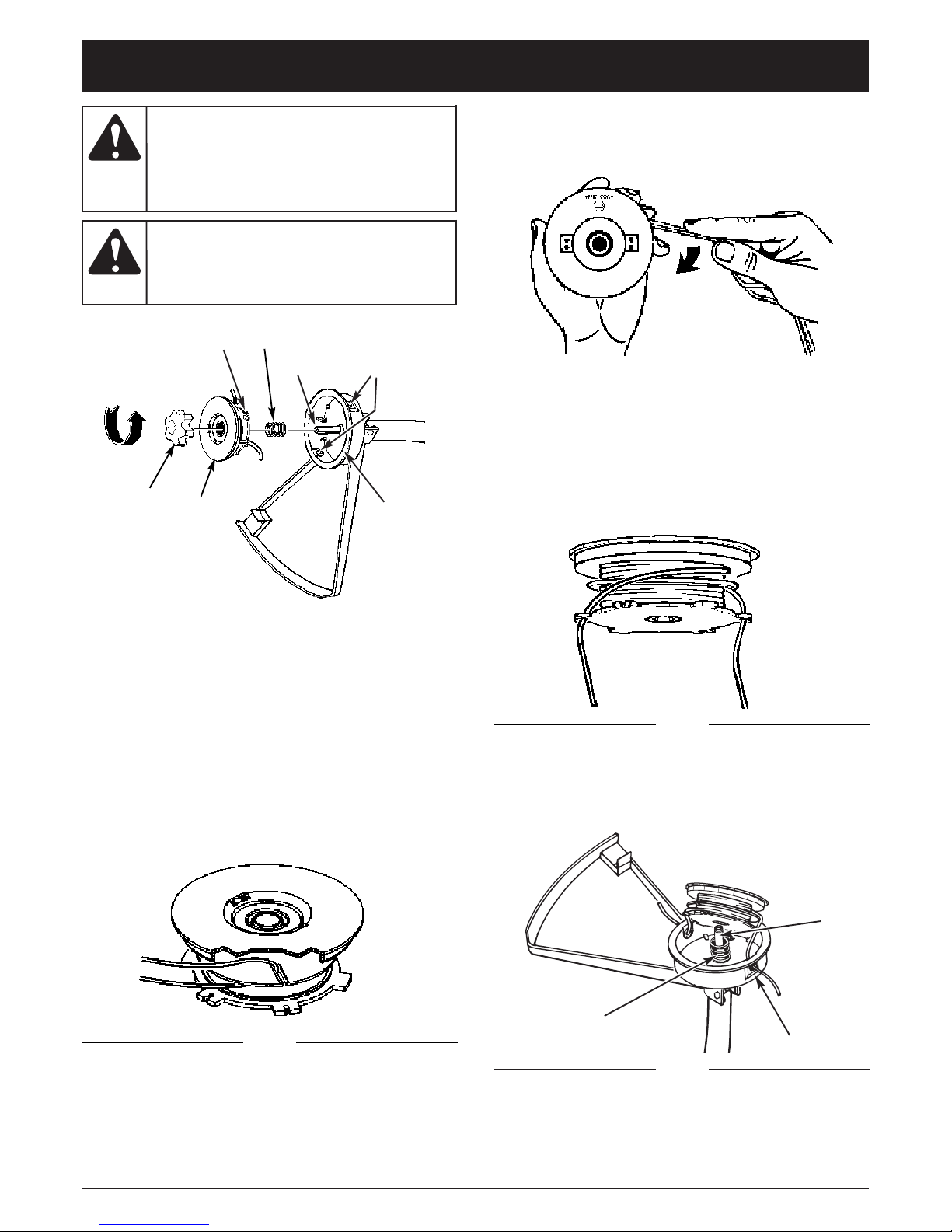
F11
REMPLACEMENT DU FIL DE COUPE
1. Tourner le bouton vers la gauche et le retirer (Fig. 14).
2. Retirer la bobine et le ressort de l’axe.
3. Retirer le restant de fil.
4. Doubler une longueur de 4,3 m (14 po) de fil de
coupe de 0,24 cm (0,095 po). Glisser le centre
bouclé dans une des encoches du séparateur de
bobiner (Fig. 15).
Bouton
Encoches
Ressort
Axe
Deillets
Faisant
Bobine
Fig. 17
Fig. 15
Fig. 16
5. Enrouler comme illustre (Fig. 16), en tenant tendu,
chaque moitié étant séparée par le séparateur de
bobine. Enrouler jusqu’à 15 cm (6 po) des extrémités.
6. Bloquer chacune des extrémités de fil dans les
encoches diamétralement opposées de l’extérieur de
la bobine (Fig. 17).
7. Placer le ressort sur l’axe. Insérer chaque extrémité
du fil dans les oeillets du boîtier (Fig. 14).
Fig. 17
Fig. 18
Encoches
8. Enfoncer la bobine tout en faisant avancer le fil dans
les oeillets. Vérifier que le ressort se positionne
correctement dans la bobine (Fig. 18).
INSTRUCCIONES DE MANTENIMIENTO Y REPARACIÓN
n'utilisez
jamais
de fil, de chaîne ou de cordon à renfort
métallique car ils peuvent se briser et se
transformer en projectile dangereux.
A VERTISSEMENT :
Ressort
Faisant
Axe
pour
éviter
tout accident, n’effectuez jamais l’entretien
ou des réparations quand l’appareil fonctionne. Effectuez-les toujours lorsqu’il est
froid. Débranchez le câble de la bougie
pour prévenir la mise en route.
A VERTISSEMENT :
Page 30
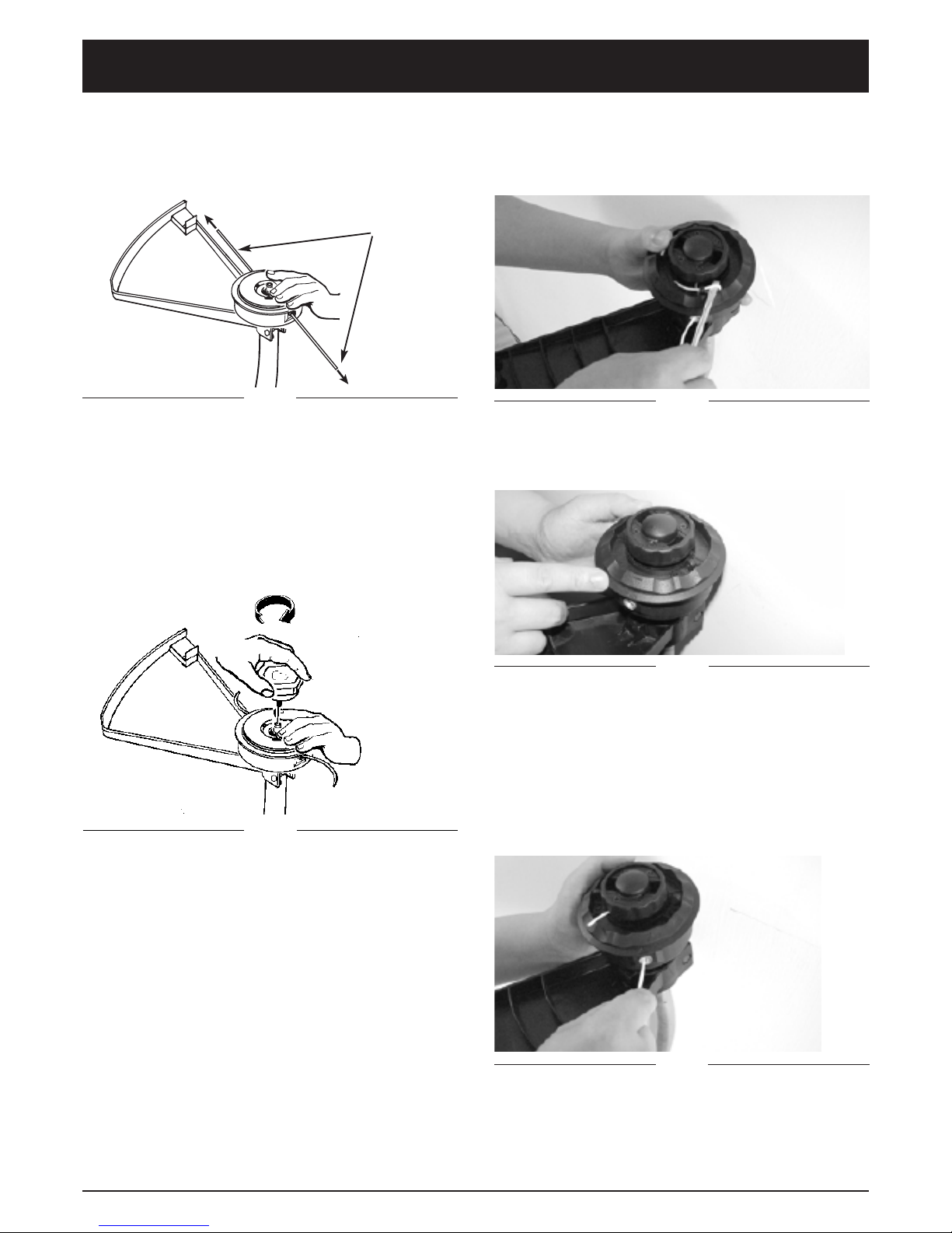
F12
Fig. 20
Fig. 19
Cutting
Line Ends
9. Une fois la bobine en place, appuyer pour compresser
le ressort. Tirer fermement sur chaque extrémité du fil
pour le dégager des encoches (Fig. 19).
10. Continuer d’appuyer sur la bobine jusqu’à ce que
l’axe dépasse suffisamment pour permenttre de
visser le bouton. Visser le bouton de gauche a droite
(Fig. 20).
11. Couper l’excédent de fil à environ 13 cm (5 po). Ceci
minimisera la charge sur le moteur pendant le
démarrage et le réchauffage.
Fig. 21
Fig. 22
LA TÊTE DE LIGNE-FACILE-CHARGE DE
COUPEUR
1. Utilisez un petit tournevis ou une tige aiguë pour
liberer la ligne des attaches qui la bloquent (Fig. 21).
2. Enlevez la ligne restante de la tête.
3. Alignez les flèches sur la bobine intérieure et externe
(Fig. 22).
4. Coupez une ligne de règlage approximativement 5
mètres de long.
5. Tout en poussant la bobine intérieure passez vers le
bas chaque extrémité de la ligne dans des oeillets
dans la fente d'alimentation sur le diviseur de
bobine. Assurez que la ligne entre dans les fentes
d'alimentation. Poussez la ligne jusqu'à ce
qu'approximativement 5 centimètres apparaissent
de dessous le bouton de bosse (Fig. 23).
Fig. 23
INSTRUCCIONES DE MANTENIMIENTO Y REPARACIÓN
Page 31

F13
6. Insérez chaque extrémité dans les attaches de
blocage en repoussant l'éxtremité de ligne par le trou
inferieur de l'attache et en faisant une boucle de
l'éxtremité par le trou de l'attache supérieure. Tirez
la ligne a l'oeillet à la tension (Fig. 24).
INSTRUCCIONES DE MANTENIMIENTO Y REPARACIÓN
Fig. 26
Fig. 25
Fig. 24
FILTRE Á AIR
Nettoyage du filtre à air:
1. Retirer les 2 vis retenant le couvercle du filtre à air
(Fig. 27).
2. Retirer le couvercle et retirer le filtre du boitier (Fig. 28).
2. Lavef le filtre à l’eau savonneuse. NE PAS UTILISER
D’ESSENCE.
4. Sécher le filtre à l’air.
5. Replacer le filtre.
REMARQUE : Si le filtre est effiloché, déchiré, endom-
magé ou síl ne peut pas être nettoyé, le remplacer.
Fig. 27
Fig. 28
Vis
Couvercle
Filtre á Air
7. Une fois que les deux extrémités de ligne sont fixés
en place tournez la bobine intérieure dans le sens
contraire des aiguilles d'une montre dans la direction
des flèches à la ligne de charge (Fig. 25).
8. Enroulez la bobine jusqu'à ce qu'une boucle de ligne
approximativement 25 centimètres de long soit
visible. Réduisez la boucle de moitié pour créer deux
extrémités de coupure de ligne. Assurez que chaque
extrémité de ligne ne soit pas de plus de 13
centimètres de long. Ceci réduira au minimum la
charge sur le moteur pendant le départ.
NE
JAMAIS
utiliser le coupe-herbe sans filtre à air. Le
filtre à air doit rester propr e. Si endommagé,
remplacer.
MISE EN GARDE:
Page 32

F14
INSTRUCCIONES DE MANTENIMIENTO Y REPARACIÓN
BOUCHON DU RESERVOIR/FILTRE A CARBURANT
REMARQUE : Veiller à ce que l’évent du bouchon soit
exempt de débris (Fig. 29).
Filtre à Carburant:
1. Sortir le tuyau d’essence et le filtre du réservoir. Un fil
de fer avec un crochet au bout peut être facilement
utilisé (Fig. 30).
2. Tirer avec un mouvement rotatif (Fig. 31).
3. Remplacer le filtre à carburant.
Fig. 29
Bouchon du
Reservoir
Fig. 31
Fil de fer
Tuyau d’essence
et le filtre
Fig. 30
Filtre á Carburant
REGLAGE DU CARBURATEUR
Le carburateur a été réglé en usine pour une performance
optimale. Si un ajustage est nécessaire, veuillez apporter
votre appareil au Centre de Service Après-Vente agréé le
plus proche dont vous trouverez l’adr esse dans les pages
jaunes de l’annuaire téléphonique.
BOUGIE
1. L’écartement de bougie = 0,635 mm (0,025 po) (Fig. 32).
2. Replacer la bougie et la serrer à 12 à 15 N•m (105 à
130 pouces-livres). Reconnecter le fil de la bougie.
Fig. 32
0.025” (0.635 mm)
Fig. 33
capot du
silenceux
Fig. 34
couvercle
de l’écran
vis de
retenue
l’écran pare-
étincelles
PARE-ETINCELLES
REMARQUE : Il n’est pas nécessaire de retirer le capot
du silenceux pour installer ou remplacer l’écran
pare-étincelles (Fig. 33).
Pour remplacer l’écran pare-étincelles, retirer la vis de
retenue et le couvercle de l’écran usagé et installer
l’écran neuf (Fig. 34).
Vider
l’essence
contenue dans le réservoir et la placer dans
un récipient homologué avant de commencer
cette opéeration. Ovrir le bouchon de
essence lentement pour soulager la pression
éventuellement accumulée dans le réservoir.
MISE EN GARDE:
Ne
jamais
utiliser le coupe-herbe sans le filtre à
carburant car ceci pourrait causer des
dommages internes au moteur!
MISE EN GARDE:
Page 33

F15
INSTRUCCIONES DE MANTENIMIENTO Y REPARACIÓN
RÉGLAGE DE LA VIS DE RÉGLAGE DE RALENTI
1. Trouvez la vis de réglage de ralenti sur le carburateur
(Fig. 36).
2. Utiliser un tournevis - tournez par 1/4 à 1/2 dans le
sens des aiguilles d'une montre (vers la droite).
L'unité devrait alors s'immobiliser normalement.
Fig. 35
pare-débris
lame
AFFUTAGE DE LA LAME PARE-DEBRIS
1. Retirer la lame du pare-débris (Fig. 35).
2. Serrer la lame dans un étau d’établi. L’affûter a l’aide
d’une lime plate en veillant à maintenir l’angle de
coupe. Limer toujours dans la même direction.
Fig. 36
EMMAGASINER L’APPAREIL
1. Effectuer tous les entretiens d’ordre général
recommandés dans la section Entretien du manuel
d’utilisation.
2. Nettoyer l’extérieur du moteur, l’arbre de
transmission, le pare-débris et la tête de coupe.
3. Vidanger le réservoir de carburant.
4. Une fois le réservoir vide, faire démarrer le moteur.
5. Laisser tourner le moteur au ralenti jusqu’à ce qu’il
s’arrête, afin de purger le carburateur de carburant.
6. Laisser refroidir le moteur (environ 5 mn).
7. Retirer la bouge à l’aide d’une clé à bougie.
8. Verser 1 cuillerée à thé d’huile 2 temps propre dans
la chambre de combustion. Tirer lentement le cordon
du lanceur plusieurs fois de manière à lubrifier les
composants internes. Remonter la bougie.
9. Placer l’appareil dans un endroit sec, frais et éloigné
de toute source d’allumage telles brûleur à mazout,
chauffe-eau, etc.
PREPARATION APRES EMMAGASINAGE
1. Retirer la bougie.
2. Tirer vigoureusement sur le cordon du lanceur de
manière à éliminer l’excès d’huile dans la chambre
de combustion.
3. Nettoyer les électrodes de la bougie et régler
l’écartement ou installer une nouvelle bougie.
4. Préparer le coupe-herbe pour son utilisation.
5. Remplir le réservoir à carburant d’un mélange
huile/essence approprié. Voir la section Carburant et
Lubrification.
Vis de réglage
de ralenti
Le non
respect des
instructions ci-dessous peut entraîner la
formation de vernis dans le carburateur et
résulter en des difficultés de démarrage ou des
dommages permanents après l’emmagasinage.
AVERTISSEMENT :
Page 34

F16
DÉPANNAGE
CAUSE SOLUTION
Accessoire de coupe engorgé d'herbes Arrêtez le moteur et nettoyez l'accessoire
Accessoire de coupe mal aligné Chargez du fil neuf
Tête de coupe sale Nettoyez le moulinet intérieur et la bobine extérieure
Fil tordu durant la recharge Démontez puis rembobinez le fil
CAUSE SOLUTION
Mauvais réglage du carburateur Faites-le régler par un concessionnaire agréé
CAUSE SOLUTION
Réservoir de carburant vide Remplissez-le de carburant bien mélangé.
Procédure de démarrage incorrecte Voir les instructions du manuel d’utilisation
Carburant vieux ou mal mélangé Drainez le réservoir/ajoutez du carburant frais
Bougie encrassée Remplacez ou nettoyez-la
Pare-étincelles colmaté Nettoyez ou remplacez le pare-étincelles
Filtre à carburant colmaté Remplacer le filtre à carburant
LE MOTEUR REFUSE DE DÉMARRER
LE MOTEUR DÉMARRE MAIS MANQUE DE PUISSANCE.
LE MOTEUR A DES RATÉS
MANQUE DE PUISSANCE SOUS LA CHARGE
CAUSE SOLUTION
Filtre à air bouché Remplacez ou nettoyez-le
Carburant vieux ou mal mélangé Drainez le réservoir/ajoutez du carburant frais
Mauvais réglage du carburateur Ajustez selon l'instruction
Position du starter incorrecte. Mettez le levier d'étrangleur en Position 3
CAUSE SOLUTION
Mauvais réglage du carburateur Faites-le régler par un concessionnaire agréé
LA TÊTE DE COUPE NE FAIT PAS AVANCER LE FIL
Si vous avez besoin d'aide, contactez votre concessionnaire agréé.
CAUSE SOLUTION
Mauvais réglage du carburateur Faites-le régler par un concessionnaire agréé
Carburant vieux ou mal mélangé Drainez le réservoir/ajoutez du carburant frais
FUMÉE EXCESSIVE
CAUSE SOLUTION
Mauvais écartement des électrodes de la bougie Nettoyer la bougie, réglar l’écartement des
électrodes ou remplacer la bougie
NE TOURNE PAS RÉGULIÈREMENT
Page 35

F17
CARACTÉRISTIQUES
MOTEUR*
ARBRE D'ENTRAÎNEMENT et ACCESSOIRE DE COUPE*
*Toutes les spécifications contenues dans ce manuel tiennent compte des dernières informations techniques disponibles au
moment de mettre sous presse. Nous nous réservons le droit d'y apporter des modifications à tout moment, sans préavis.
Type de moteur ............................................................................................................................. Refroidi par air, 2-temps
Cylindrée..................................................................................................................................................... 32 cc (1,95 po
3
)
Type d'allumage ................................................................................................................................................ Électronique
Écartement de la bougie.................................................................................................................... 0,635 mm (0,025 po)
Lubrification................................................................................................................................... Mélange carburant/huile
Rapport carburant/huile................................................................................................................................................ 40:1
Carburateur.............................................................................................................................. Membrane, toutes positions
Transmission ............................................................................................................................................................. Directe
Capacité du réservoir de carburant........................................................................................................ 689,7 ml (23,3 oz)
Logement de l'arbre d'entraînement ........................................................................................................... 122 cm (48 po)
Poids de l’appareil (à vide) .......................................................................................................................... 5.1 kg (11.2 lb)
Diamètre du fil ...................................................................................................................................... 2,03 mm (0,080 po)
Diamètre du chemin de coupe ................................................................................................................. 43,18 cm (17 po)
Page 36

GARANTIE LIMITÉE DU FABRICANT POUR:
Aucune garantie implicite, y compris toute garantie de
valeur marchande ou d’adaptation à une fin particulière,
ne s’applique après la période applicable de garantie
expresse écrite ci-dessus concernant les pièces qui sont
identifiées. Aucune autre garantie ou caution expresse,
écrite ou orale, à l’exception de celle mentionnée cidessus, accordée par toute personne ou entité, y compris
tout distributeur ou détaillant, concernant tout produit
n’engagera la responsabilité de MTD. Pendant la période
destates garantie, le remède exclusif est la réparation ou
le remplacement du produit dans les conditions énoncées
ci-dessus.
(Certains états ne permettent pas la limitation de la
garantie implicite, il est donc possible que la limitation cidessus ne s’applique pas à vous.)
Les clauses énoncées dans la présente Garantie
constituent le recours unique et exclusif inhérent aux
ventes. MTD ne sera en aucun cas tenue pour
responsable de tout dommage indirect ou consécutif ou
de dommages comprenant, entre autres mais pas
seulement, les dépenses encourues du fait du recours à
des services de remplacement ou de substitution pour
l’entretien des pelouses, le transport ou des frais
connexes, ou les frais entraînés par une location
destinée à remplacer provisoirement un produit sous
garantie.
(Certains états ne permettent pas la limitation de
la garantie implicite, il est donc possible que la limitation cidessus ne s’applique pas à vous.)
Aucun recouvrement, quel qu’il soit, ne sera d’un montant
supérieur au prix du produit vendu. Toute modification des
dispositifs de sécurité du produit annulera la présente
Garantie. Vous assumez tout risque et toute responsabilité
résultant de la perte, de l’endommagement ou du préjudice
que vous et votre propriété et/ou d’autres et leur
propriété pourront encourir du fait de l’utilisation normale,
de la mauvaise utilisation ou de l’empêchement d’utiliser le
produit.
La présente garantie limitée n’est accordée qu’à l’acheteur
initial, au preneur initial ou à la personne à laquelle le produit
a été offert.
Le Droit des États vis à vis de la présente garantie : la
présente garantie vous confère certains droits juridiques, et
vous pouvez bénéficier d’autres droits, lesquels varient
d’une juridiction à l’autre.
Pour obtenir l’adresse du distributeur agréé le plus proche,
composer le : 1-800-345-8746 aux États-Unis ou le
1-800-668-1238 au Canada.
MTD LLC
P.O. Box 361131
Cleveland, OH 44136-0019
La garantie limitée énoncée ci-après est accordée par MTD
LLC (« MTD ») et concerne les marchandises neuves achetées
et utilisées aux États-Unis, ainsi que dans leurs possessions et
territoires.
MTD garantit ce produit contre tout vice de matière ou de
façon pendant une période de deux (2) ans à compter de la
date d’achat initiale et elle se réserve le choix de réparer ou de
remplacer, à titre gratuit, toute pièce présentant un vice de
matière ou de façon. Cette garantie limitée nes’ appliquera
que dans la mesure où le produit aura été utilisé et entretenu
conformément au Guide de l’utilisateur fourni avec le produit
et n’aura pas fait l’objet d’un usage inadéquat, abusif,
commercial ou négligent, d’un accident, d’un entretien
inadéquat, d’une modification, de vandalisme, d’un vol, d’un
incendie, de dégâts d’eau ou d’un endommagement résultant
d’un autre péril ou d’un désastre naturel. Les dommages
résultats de l’installation ou de l’utilisation de tout accessoire
ou équipement non approuvé par MTD pour une utilisation
avec le(s) produit(s) couvert(s) par le présent guide annuleront
la garantie et ce qui concerne les dommages qui en
résulteraient éventuellement.La présente garantie est limitée à
quatre-vingt-dix (90) jours à compter de la date d’achat au
détail initiale pour tout produit MTD utilisé à des fins locatives
ou commerciales, ou toute utilisation produisant des revenus.
POUR L’ENTRETIEN-DÉPANNAGE : l’Entretien-dépannage
au titre de la garantie est disponible, SUR PRÉSENTATION
DE PREUVE D’ACHAT, AUPRÈS DU DISTRIBUTEUR AGRÉÉ
LOCAL. Pour obtenir le nom du distributeur agréé local,
consulter les Pages Jaunes ou se mettre en rapport avec le
Service après-vente de MTD LLC. en appelant le 1-800345-8746 ou en écrivant au P.O. Box 361131, Cleveland OH
44136-0019 ou en appelant le 1-800-668-1238 au Canada.
Aucun produit retourné à l’usine sans permission écrite
préalable du service après-vente de MTD LLC ne sera
accepté.
La garantie limitée n’offre aucune couverture dans les
cas suivants :
A. Mises au point – Bougies, réglages de carburateur,
filtres.
B. Articles d’usure – Bouton de butée, bobines extérieures, fil
de coupe, bobines intérieures, poulie de démarrage,
cordes de démarrage, courroies d’entraînement.
C. MTD n’accorde aucune garantie pour les produits
vendus ou exportés des États-Unis, de leurs
possessions et territoires, exception faite en ce qui
concerne les produits vendus par l’intermédiaire de ses
canaux agréés de distribution à l’exportation.
MTD se réserve la droit de modifier ou d’améliorer la
conception de tout produit MTD sans assumer l’obligation
de modifier tout produit d’une fabrication plus ancienne.
Page 37

IMPORTANTE: LEA LAS REGLAS DE SEGURIDAD Y
INSTRUCCIONES DETENIDAMENTE
P/N 9096-333606 © 2004
HECHO EN CHINA
Recortador a
Gasolina
MCT33360E
Manuel del Dueño/Operador
Español
Page 38

E2
Antes de arrancar u operar este equipo, asegúrese de
leer y comprender bien este manual.
ESTE PRODUCTO ESTA CUBIERTO POR UNA O MAS
PATENTES DE EE.UU., OTRAS PATENTES EN TRAMITE.
Antes de que empiece a ensamblar su nuevo equipo,
por favor ubique la placa que contiene el modelo de la
unidad y escriba esa información en el espacio en
blanco aquí debajo. Aquí debajo se explica la muestra
de una placa del modelo.
INTRODUCCION
Copie el número del modelo/
pieza del fabricante aquí:
Copie el número
de serie aquí:
MUCHAS GRACIAS
Gracias por haber adquirido este gran producto. Esta
moderna herramienta motriz de exteriores está diseñada
para brindarle muchas horas de servicio útil. Usted
comprobará que es un artefacto que le ahorrará mucho
trabajo. Este manual del operador le brinda instrucciones
de operación de fácil comprensión. Lea todo el manual y
siga todas las instrucciones para mantener su nueva
herramienta motriz de exteriores en las mejores
condiciones de funcionamiento.
REFERENCIAS, ILUSTRACIONES Y ESPECIFICACIONES DEL PRODUCTO
Toda la información, las ilustraciones y las especificaciones
contenidas en este manual se basan en la información
más reciente disponible en el momento de impresión del
manual. Nos reservamos el derecho de hacer cambios
en cualquier momento sin aviso previo.
Copyright© 2004 MTD SOUTHWEST INC. Todos los
derechos reservados.
INFORMACION DEL SERVICIO
El servicio de esta unidad, ya sea durante o después del
período cubierto por la garantía, debe ser realizado
solamente por un proveedor de servicios autorizado y
aprobado.
El servicio de esta unidad, ya sea durante o después del
período cubierto por la garantía, debe ser realizado
solamente por un proveedor de servicios autorizado y
aprobado. Llame 1-800-345-8746 en EE.UU. o al 1-800-
668-1238 en Canada para obtener una lista de
distribuidores de servicio localizados cerca de usted.
Para obtener más detalles sobre su unidad, visite
nuestro sitio en www.yardmachines.com.
NO REGRESE SU UNIDAD AL VENDEDOR. PARA
SOLICITAR SERVICIO POR LA GARANTIA, DEBERA
PRESENTAR PRUEBA DE SU COMPRA.
S/N :
ITEM :
MODEL :
INDICE DE CONTENIDOS
Introduccion . . . . . . . . . . . . . . . . . . . . . . . . . . . . . . .2
Normas para una operación segura . . . . . . . . . . . . .3
Conozca su unidad . . . . . . . . . . . . . . . . . . . . . . . . . 6
Instrucciones de ensamble . . . . . . . . . . . . . . . . . . . .7
Información del aceite y del combustible . . . . . . . . .8
Instrucciones de arranque y apagado . . . . . . . . . . .9
Instrucciones de operación . . . . . . . . . . . . . . . . . .10
Instrucciones de mantenimiento y reparación . . . .11
Cuadro de solución de problemas . . . . . . . . . . . . .16
Especificaciones . . . . . . . . . . . . . . . . . . . . . . . . . . .17
Garantía . . . . . . . . . . . . . . . . . . . . . . . . . . . . . . . . . .20
Lista de Piezas . . . . . . . . . . . . . . . . . .Contraportada
Número de la
pieza del fabricante
Número de serie
Número del
modelo
PARACHISPAS
NOTA: Para los usuarios en tierras forestales de los
EE.UU. y en los estados de California, Maine, Oregon
y Washington. Todos los terrenos forestales de los
EE.UU. y el estado de California (Códigos de Recursos
Públicos 4442 y 4443), Oregon y Washington, requieren
por decreto, que ciertos motores de combustión interna
que se hagan funcionar en zonas boscosas y/o zonas
cubiertas por pastizales, estén equipados con un
parachispas, que sean mantenidos en buen estado de
funcionamiento o que el motor sea construido, esté
equipado y sea mantenido para evitar incendios.
Consulte los reglamentos pertinentes a esos requisitos
con las autoridades estatales o locales. El incumplimiento
de esos requisitos puede responsabilizarle o someterle a
la imposición de una multa. Esta unidad fue equipada
en la fábrica con un parachispas. Si requiere sustitución,
hay una Pantalla Parachispas disponible, Pieza #
182747 al contactar el departamento de servicio.
ADVERTENCIA
LAS EMISIONES DEL MOTOR DE ESTE
PRODUCTO CONTIENEN SUBSTANCIAS
QUIMICAS QUE EL ESTADO DE CALIFOR-
NIA CONOCE COMO CAUSANTES DECAN-
CER, DEFECTOS DE NACIMIENTO U
OTROS DAÑOS REPRODUCTIVOS.
PROPOSICIÓN 65 DE CALIFORNIA
Page 39

E3
NORMAS PARA UNA OPERACION SEGURA
SIMBOLO SIGNIFICADO
Los símbolos de seguridad se utilizan para llamar su
atención sobre posibles peligros. Los símbolos de
seguridad y sus explicaciones merecen toda su atención
y comprensión. Los símbolos de seguridad no eliminan
ningún peligro por sí mismos. Las instrucciones o
advertencias que ofrecen no substituyen las medidas
adecuadas de prevención de accidentes.
SIMBOLO SIGNIFICADO
El no
seguir una
advertencia de seguridad puede conducir a
que usted u otras personas sufran lesiones.
Siga siempre las precauciones de seguridad
para reducir el riesgo de incendio, descarga
eléctrica y lesiones personales.
ADVERTENCIA:
El no obedecer una
advertencia de
seguridad puede conducir a que usted u
otras personas sufran graves lesiones. Siga
siempre las precauciones de seguridad
para reducir el riesgo de incendio, descarga
eléctrica y lesiones personales.
PELIGRO:
El no seguir
una
advertencia de seguridad puede conducir a
daño patrimonial o a que usted u otras
personas sufran lesiones personales. Siga
siempre las precauciones de seguridad
para reducir el riesgo de incendio, descarga
eléctrica y lesiones personales.
PRECAUCION:
Indica peligro, advertencia o precaución.
Debe prestar atención para evitar sufrir
graves lesiones personales. Puede ser
utilizado junto con otros símbolos o figuras.
ALERT A DE SEGURIDAD
:
NOTA: Le ofrece información o instrucciones que son
esenciales para la operación o mantenimiento
del equipo.
Lea el manual del operador y siga todas las adver-
tencias e instrucciones de seguridad. De no hacerlo,
el operador y/o los espectadores pueden sufrir
graves lesiones.
SI TIENE PREGUNTAS, LLAME AL 1-800-345-8746
EN EE.UU. O AL 1-800-668-1238 en CANADA
LEA TODAS LAS INSTRUCCIONES
ANTES DE LA OPERACION
• Lea todas las instrucciones con cuidado. Conozca
bien los controles y el uso correcto de la unidad.
• No opere esta unidad si está cansado, enfermo, o
bajo los efectos del alcohol, drogas o medicamentos.
• Los niños y los adolescentes menores de 15 años no
deben operar las unidades, excepto por los adolescentes guiados por un adulto.
• Inspeccione la unidad antes de utilizarla. Cambie las
partes dañadas. Verifique si existen pérdidas de combustible. Asegúrese de que los sujetadores estén bien
colocados y asegurados. Cambie las partes accesorias de
corte que estén quebradas, cascadas o dañadas de
cualquier forma. Asegúrese de que el accesorio de corte
está bien instalado y ajustado con firmeza. Asegúrese de
que la protección accesoria de corte esté bien conectada
y colocada según se recomienda.
• Use sólo línea de repuesto fabricante del equipo original de 2,41 mm (0,095 pulgadas) de diámetro. Nunca
use línea con refuerzo de metal, cable, soga, etc. Estas
pueden desprenderse y convertirse en un proyectil peligroso.
• Tenga en cuenta el riesgo de lesiones en la cabeza, manos
y pies.
• Oprima el control del regulador y verifique que regrese
automáticamente a la posición de mínima. Haga todos
los ajustes o reparaciones antes de usar la unidad.
• Esta unidad no fue diseñada para ser usada como
cortamalezas. No conecte ni opere esta unidad con
ningún tipo de cuchilla ni accesorio para cortar malezas.
• Limpie el área de corte antes de cada uso. Retire todos
los objetos como rocas, vidrios rotos, clavos, alambre o
cuerda los cuales pueden ser despedidos o enredarse
en el accesorio de corte. Aleje a todos los niños, espectadores y animales domésticos. Mantenga todos los
niños, espectadores y animales domésticos a un radio
de por lo menos 15 m (50 pies); aún así puede existir un
riesgo de objetos despedidos contra los espectadores.
Debe sugerir a los espectadores que usen protección
ocular. Si alguien se le acerca, pare el motor y el accesorio de corte de inmediato.
ADVERTENCIAS DE SEGURIDAD PARA LOS
RECORTADORES A GASOLINA
• Guarde el combustible en envases que hayan sido
diseñados y aprobados para el almacenamiento de
dichos materiales.
• Antes de llenar el tanque de combustible, apague
siempre el motor y espere que se enfríe. No retire
nunca la tapa del tanque de combustible ni cargue
combustible mientras el motor esté caliente. No opere
nunca la unidad sin la tapa del combustible colocada
firmemente en su lugar. Afloje la tapa del combustible
lentamente para disipar la presión del tanque.
• IMPORTANTE INFORMACION DE SEGURIDAD •
La gasolina
es muy
inflamable y sus gases pueden explotar si se
encienden. Tome las siguientes precauciones:
ADVERTENCIA:
Se debe
seguir las
siguientes reglas de seguridad cuando use la
unidad. Por favor lea estas instrucciones para
su propia seguridad y las de los espectadores,
antes de hacer funcionar la unidad. Por favor
mantenga estas instrucciones en un lugar
seguro para uso futuro.
ADVERTENCIA:
Page 40

E4
NORMAS PARA UNA OPERACIÓN SEGURA
• Mezcle y cargue el combustible en un área exterior
bien ventilada donde no haya chispas ni llamas. Quite
lentamente la tapa del combustible sólo después de
apagar el motor. No fume mientras carga o mezcla el
combustible. Limpie de inmediato todo el combustible
que se haya derramado.
• Evite crear una fuente de encendido por combustible
derramado. No arranque el motor hasta que se hayan
disipado los vapores del combustible.
• Aleje la unidad a por lo menos 9,1 m (30 pies) del
lugar de carga de combustible antes de arrancar el
motor. No fume, mantenga las chispas y las llamas
abiertas lejos del área mientras carga el combustible
u opera la unidad.
DURANTE LA OPERACION
• No arranque ni opere la unidad en una sala o edificio
cerrado. Los gases de escape de monóxido de carbono pueden ser letales en un área cerrada. Opere
esta unidad sólo en un área exterior bien ventilada.
• Use lentes o gafas de protección que cumplan con
las normas ANSI Z87.1-1989, y protección para sus
oídos/audición mientras opere esta unidad. Use siempre una máscara facial o para protegerse contra el
polvo si la operación levanta polvo.
• Use pantalones largos y gruesos y guantes. No vista
ropa holgada, alhajas, pantalones cortos, sandalias ni
esté descalzo. Asegure su cabello sobre el nivel de
los hombros.
• La protección accesoria de corte debe estar siempre
colocada en su lugar mientras opere la unidad. No
opere la unidad con las dos líneas de corte extendidas, y la línea correcta instalada. No extienda la línea
de corte más allá de la longitud de la protección.
• Ajuste la manija de acuerdo a su medida para lograr
el mejor agarre.
• Asegúrese de que el accesorio de corte no está en
contacto con ningún objeto antes de arrancar la
unidad.
• Use la unidad únicamente con la luz del día o con
buena luz artificial.
• Evite arrancar la unidad accidentalmente. Colóquese
en posición de inicio siempre que tire de la cuerda de
arranque. El operador y la unidad deben estar en una
posición estable al comenzar. Lea las instrucciones de
Arranque y Apagado.
• Use la herramienta adecuada. No use esta unidad
para ninguna tarea para la cual no ha sido diseñada.
• No se estire demasiado. Mantenga siempre una posición y equilibrio adecuados.
• Sostenga siempre la unidad con ambas manos mientras esté en funcionamiento. Sostenga con firmeza
tanto el mango como la manija auxiliar.
• Mantenga las manos, la cara y los pies lejos de todas
las partes móviles. No intente tocar ni detener el
accesorio de corte mientras gira.
• No toque el silenciador ni el cilindro. Estas partes se
calientan mucho con la operación. Luego de apagarlas permanecen calientes durante un corto tiempo.
• No opere el motor a una velocidad mayor que la
necesaria para cortar, recortar o recortar los bordes.
No haga funcionar el motor a alta velocidad mientras
no está cortando.
• Apague siempre el motor cuando demore el corte o
mientras camina entre zonas de corte.
• Si golpea o se enreda con algún objeto extraño,
apague el motor de inmediato y verifique si hay
daños. Repare todos los daños antes de volver a
intentar operar la unidad. No opere la unidad si tiene
piezas flojas o dañadas.
• Apague el motor para realizar todo el mantenimiento,
reparaciones o cambio del accesorio de corte u otros
accesorios.
• Use sólo piezas y accesorios de repuesto fabricante
del equipo original para esta unidad. Estas piezas
están disponibles en su distribuidor autorizado. No
use piezas, accesorios ni auxiliares que no hayan sido
diseñados para esta unidad. Su uso puede conducir a
que el usuario sufra graves lesiones o al daño de la
unidad y a la invalidación de su garantía.
• Mantenga la unidad libre de vegetación y otros materiales. Pueden alojarse entre el accesorio de corte y la
protección.
• Para reducir el riesgo de incendio, cambie los silenciadores y amortiguadores de chispas defectuosos,
mantenga el motor y el silenciador libre de pasto,
hojas, grasa excesiva o acumulaciones de carbono.
• Apague el motor DE INMEDIATO si siente una
vibración excesiva. La vibración es un signo de que
hay problemas. Inspeccione bien si hay tuercas o pernos flojos o si hay daños antes de continuar. Repare o
cambie las piezas afectadas según sea necesario.
• No levante la cabeza de hilo arriba del nivel del piso
mientras esté operando la unidad.
OTRAS ADVERTENCIAS DE SEGURIDAD
• No guarde nunca la unidad con combustible en el
tanque en un edificio donde los gases puedan llegar a
una llama abierta o a una chispa.
• Espere que el motor se enfríe antes de guardar o
transportar la unidad. Asegúrese de que la unidad
esté segura al transportarla.
• Guarde la unidad bajo llave en un lugar adecuado y
seco para evitar que sea usada por personas no
autorizadas y se dañe, fuera del alcance de los niños.
• Nunca moje ni rocíe la unidad con agua ni con ningún
otro líquido. Mantenga las manijas secas, limpias y sin
residuos. Limpie la unidad luego de cada uso, lea las
instrucciones de Limpieza y Almacenamiento.
• Guarde estas instrucciones. Consúltelas con frecuencia y utilícelas para enseñar a otros usuarios. Si le
presta esta unidad a alguien, préstele también estas
instrucciones.
CONSERVE ESTAS
INSTRUCCIONES
Page 41

E5
NORMAS PARA UNA OPERACIÓN SEGURA
SIMBOLO SIGNIFICADO
• SIMBOLO DE ALERTA DE
SEGURIDAD
IIndica peligro, advertencia o precaución. Puede ser utilizado junto con
otros símbolos o figuras.
• ADVERTENCIA - LEA EL MANUAL
DEL OPERADOR
Lea el manual del operador y siga todas
las advertencias e instrucciones de
seguridad. De no hacerlo, el operador
y/o los espectadores pueden sufrir
graves lesiones.
• USE PROTECCION OCULAR,
AUDITIVA Y EN SU CABEZA
ADVERTENCIA : Los objetos arrojados
por la unidad y el ruido fuerte pueden
causar graves lesiones oculares y pérdida auditiva. Utilice protección ocular
que cumpla con las normas ANSI Z87.1
y protección auditiva cuando opere
esta unidad. Los objetos que caen
pueden causar graves lesiones en su
cabeza. Use protección en su cabeza
mientras opere esta unidad. Use una
careta completa cuando la necesite.
• USE GUANTES
• USE CARGADORES
SIMBOLO SIGNIFICADO
• LOS OBJETOS DESPEDIDOS Y
LA CUCHILLA ROTATIVA PUEDEN
CAUSAR GRAVES LESIONES
ADVERTENCIA: No opere esta
unidad si la protección plástica de
línea no está colocada en su lugar.
Manténgase alejado del accesorio de
corte giratorio.
• MANTENGA ALEJADOS A LOS
ESPECTADORES
ADVERTENCIA: Mantenga a todos los
espectadores, en especial a niños y animales domésticos a por lo menos 15 m
(50 pies) del área de corte.
• CONTROL DEL OBTURADOR
1 • Posición de OBTURACIÓN
COMPLETA
2 • Posición de OBTURACIÓN
PARCIAL
3 • Posición de MARCHA
• ADVERTENCIA DE SUPERFICIE
CALIENTE
No toque un silenciador ni un cilindro
caliente. Puede quemarse. Estas partes
se calientan mucho con el uso. Luego
de apagarse permanecen calientes
durante un corto tiempo.
• NO UTILICE LAS CUCHILLAS
SIMBOLOS DE SEGURIDAD E INTERNACIONALES
Este manual del operador describe los símbolos y figuras de seguridad e internacionales que pueden aparecer en este
producto. Lea el manual del operador para obtener información completa acerca de la seguridad, ensamble, operación y
mantenimiento y reparación.
Page 42

E6
NORMAS PARA UNA OPERACIÓN SEGURA
CONOZCA SU UNIDAD
Mango de la cuerda
de arranque
Control del
regulador
Protector accesorio
de corte
Accesorio de corte
Manija
Bastidor
del eje
Traba del
regulador
Control de
encendido y
apagado
Tapa del
combustible
Palanca del
obturador
Bombilla
del cebador
Cubierta del
silenciador
Tanque de
Combustible
Cubierta del
filtro de aire
Rudeade
Guía de
Extremo
Page 43

E7
INSTALACIÓN Y AJUSTE DE LA MANIJA
El manubrio Delta está unido al eje pero está volteado
hacia abajo para facilitar el empaque.
1. Empuje la manija en D hacia abajo sobre el bastidor
del eje.
2. Introduzca el perno a través de la manija y asegúrelo
con la arandela y la tuerca (Fig. 1).
3. Ajuste la manija para caber al operador y para apretar la tuerca de mariposa.
Fig. 1
INSTALACION DEL PROTECTOR ACCESORIO DE CORTE
NOTA: El protector de desechos debe instalarse de tal
forma que elimine la línea de la cortadora y proteja al operador.
El protector encaja perfecto en el eje. Puede necesitarse
algo de fuerza.
1. Fije el protector en las ménsulas del eje (Fig. 2).
2. Insterte el tornillo, la tuerca, la arandela y la arandela
de seguridad y apriete firmemente (Fig. 3).
Bracket
Fig. 3
Fig. 4
RUEDA DE GUÍA DE MARGEN
1. Empuja la rueda de guía de margen en el eje (Fig. 4).
Se requiere algo de fuerza.
Fig. 2
INSTRUCCIONES DE OPERACIÓN
No opere
nunca la
recortadora sin el protector accesorio de
corte colocado en su lugar para evitar
graves lesiones personales.
ADVERTENCIA:
Protector accesorio
de corte
Manija
Perno
Arandela
Tuerca de
mariposa
Bastidor
del eje
Tuerca de mariposa
Perno
Arandela de Seguridad
Arandela
Perno
Rueda de guía
de margen
Arandela
Tuerca de
mariposa
Tuerca
2. Inserta el pern, la arandela, y tuerca para luego
apretarlos bien.
3. Ajusta la profundidad de margen afloojando la tuerca
y moviendo en la posición deseada a lo largo de la
flecha indicada para luego apretarlos bien (Fig. 4).
Page 44

E8
INFORMACION DEL ACEITE Y DEL COMBUSTIBLE
NOTA: Elimine la mezcla vieja de aceite y combustible
de acuerdo con los reglamentos federales,
estatales y locales.
INSTRUCCIONES PARA MEZCLAR EL
ACEITE Y EL COMBUSTIBLE
El combustible viejo o mal mezclado son los motivos
principales del mal funcionamiento de la unidad.
Asegúrese de usar combustible nuevo, limpio y sin
plomo. Siga las instrucciones en detalle para mezclar
correctamente el aceite y el combustible.
Definición de los combustibles de mezcla
Los combustibles actuales con frecuencia son una mezcla
de gasolina y oxigenantes como por ejemplo etanol,
metanol o MTBE (éter). El combustible mezclado con
alcohol absorbe agua. Una cantidad tan pequeña como el
1% de agua en el combustible puede causar la separación del combustible y el aceite. Forma ácidos cuando
está almacenado. Cuando use combustible mezclado con
alcohol, use combustible nuevo (de menos de 60 días).
Uso de combustibles de mezcla
Si usted opta por usar un combustible de mezcla o si
su uso es inevitable, tome las precauciones recomendadas.
• Use siempre una mezcla fresca de combustible según
lo indica su manual del operador.
• Agite siempre la mezcla de combustible antes de cargarlo en la unidad.
• Drene el tanque y haga funcionar el motor en seco
antes de guardar la unidad.
Uso de aditivos en el combustible
La botella de aceite de 2 ciclos que vino con su unidad
contiene un aditivo en el combustible que ayudará a
inhibir la corrosión y a reducir la formación de depósitos
de goma. Se recomienda que use sólo el aceite de 2
ciclos con esta unidad.
Si es inevitable, use un buen aceite de 2 ciclos elaborado para motores enfriados por aire junto con un aditivo
para el combustible como por ejemplo el estabilizador
de gasolina STA-BIL®o similar. Agregue 23 mL (0,8
onzas) de aditivo de combustible por galón de combustible de acuerdo con las instrucciones del envase.
NUNCA agregue aditivos directamente en el tanque de
combustible de la unidad.
Mezcle bien la proporción correcta de aceite para motor
de 2 ciclos y gasolina sin plomo en una lata de combustible por separado. Use una proporción de 40:1 de
combustible y aceite. No los mezcle directamente en el
tanque de combustible de la unidad. Consulte las proporciones específicas de mezcla de gasolina y aceite en
la tabla siguiente.
NOTA: 3,8 litros (un galón) de gasolina sin plomo mez-
clada con una botella de 95 mL (3,2 onzas) de
aceite de 2 ciclos es una proporción de 40:1 de
combustible y aceite.
GASOLINA SIN PLOMO ACEITE DE 2 CICLOS
3,8 LITROS
(1 GALON de EE.UU.)
95 mL
(3,2 ONZAS FLUIDAS)
1 LITRO 25 mL
+
PROPORCION DE LA MEZCLA = 40 : 1
Para que el
motor funcione correctamente y con la mayor fiabilidad, preste mucha atención a las instrucciones de mezcla de aceite y combustible del
envase de aceite de 2 ciclos. El uso de combustible mezclado en forma incorrecta puede
dañar seriamente el motor.
PRECAUCION:
Cargue el
combustible en un área exterior limpia y bien
ventilada. Limpie de inmediato todo combustible que se haya derramado. Evite
crear una fuente de encendido con el combustible derramado. No arranque el motor
hasta que se hayan evaporado los gases
del combustible.
ADVERTENCIA:
Saque la
tapa del
combustible lentamente para evitar lesionarse con el rociado del combustible. No
opere nunca la unidad sin la tapa del combustible firmemente colocada en su lugar.
ADVERTENCIA:
La gasoli-
na es muy
inflamable. Los gases pueden explotar si se
encienden. Apague siempre el motor y
espere que se enfríe antes de cargar el
tanque de combustible. No fume mientras
llena el tanque. Mantenga las chispas y las
llamas lejos del área.
ADVERTENCIA:
NOTA: La falta de lubricación invalida la garantia del
motor. Nunca utilizar gasolina pura en la unidad.
Page 45
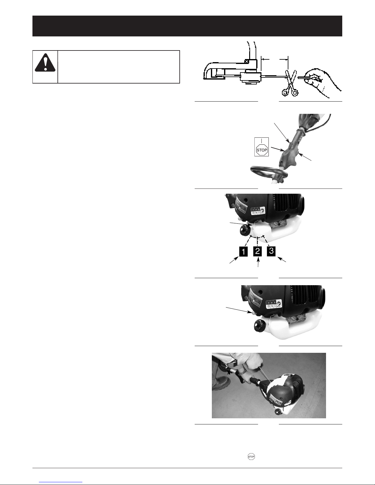
E9
INSTRUCCIONES DE ARRANQUE Y APAGADO
Fig. 6
ARRANQUE DEL MOTOR FRIO
NOTA: Para minimizar la carga del motor durante el
arranque y el calentamiento, sjustar la línea excedente de la cortadora a 13cm (5 pulg.) (Fig. 5).
1. Mezcle la gasolina con el aceite. Llene el tanque de
combustible con la mezcla de combustible/aceite.
Vea Mezclar el Aceite y el Combustible.
2. Colocar el interruptor de ignición en la posición
Marcha (Fig. 6).
3. Coloque la palanca del obturador en Posición 1 (Fig. 7).
4. Cebe el carburador; el bulbo de cebado 10 veces
(Fig. 8).
5. Tome la manija firmement - presione el gatillo de
seguridad y estrangule el obturador hasta la
posoción de Estrangulación Total (Fig. 6).
6. Jale la cuerda del mecanismo de arranque un poco
hasta que se sienta la resistencia, (aprox. 10.5 cm). Se
requiere un jalón rápido y suave para un encendido
potente de bujías. Jale la cuerda del mecanismo de
arranque enérgicamente 4 veces (Fig. 9).
7. Coloque la palanca del obturador en Posición 2.
8. Jale otra vez la cuerda del mecanismo de arranque 4
veces.
9. Una vez que el motor haya arrancado, deje el ahogador
en la posición de Arranque durante 10 segundos.
9. Coloque la palanca del obturador en Posición 3. The
trimmer is ready for use.
Si el motor no arranca, repita los pasos 2 al 10.
NOTA: La cuerda del mecanismo de arranque siempre
se debe jalar hacia arriba. Si el mecanismo de
arranque se jala en angulo, se provocaára que le
cuerda haga fricción contra el ohillo. Esta fricción
hará que la cuerda se desgaste y se rompa con
más rapidez. Sostener siempre el mango del
mecanismo de arranque cuando la cuerda se
contraiga. No dejar nunca que la cuerda se
regrese bruscamente de la posición extendida.
Esto podria ocasionar que la cuerda se enrede y
se desgaste y también puede dañar el ensamble
del mecanismo de arranque.
NOTA: En ciertos casos, por condiciones de operación
(altura, temperatura etc.), su sierra de cadena
necesitará un poco de ajuste para lograr la
velocidad de parado. Si el aparato no queda
parado luego de reiniciar 2 veces, siga Ajuste del
tornillo de marcha lenta.
ARRANQUE DEL MOTOR CALIENTE
1. Colocar el interruptor de ignición en la posición
Marcha (Fig. 6).
2. Coloque la palanca del obturador en Posición 1 (Fig. 7).
3. Tomar con firmeza el mango de la aceleración,
oprimir el gatillo de aceleración a la posición Total.
4. Jalar la cuerda del mecanismo de arranque con
fuerza hasta que arranque el motor, pero no más de 6
veces. Mantener la aceleración en la posición Total
hasta que el motor opere suavemente.
NOTA: Si el motor no arranca, colocar el ahogador en la
posición Correr y jalar la cuerda del mecanismo
de arranque 5 veces más. Si el motor sigue sin
arrancar, quizás está ahogado. Esperar 5 minutos y repetir el procedimiento con el ahogador en
la posición de Correr con la aceleración totalmente abierta.
Fig. 5
13 cm
(5 pulg.)
Fig. 7
Gatillo de seguridad
Fig. 8
Interruptor
de ignición
Fig. 9
Use esta
unidad
sólo en un área exterior bien ventilada. Los
gases de escape de monóxido de carbono
pueden ser letales en un área cerrada.
ADVERTENCIA:
Control del
regulador
Fig. 8
INSTRUCCIONES DE APAGADO
Soltar el gatillo de admisión. Dejar que el motor regrese
a la marcha en neutral. Mueva el interruptor de encendidio
a la posición "STOP " para detener el motor.
Posición 1
Posición 2
Posición 3
Palanca del
obturador
Bombilla
del cebador
Page 46

E10
Fig. 10
Fig. 11
AJUSTE DE LA LONGITUD DE LA LINEA DE CORTE
Para liberar la línea nueva, operar el motor en aceleración
total y “golpear” la cabeza de hilo contra el césped. La
línea se liberará en forma automática. La cuchilla del
protector de desechos cortará la línea excedente (Fig. 10).
PROCEDIMIENTOS DE PODA
NOTA: Incluso haciéndolo con cuidado, la poda alrede-
dor de cimientos, paredes de piedra o ladrillos,
curvas, etc. provocará un desgaste en las cuerdas fuera de lo normal.
Podar / Segar
Balancear la recortadora con un movimiento en forma
de hoz de lado a lado. No inclinar la cabeza de hilo
durante el procedimiento. Probar el área que se va a
podar para la altura adecuada del corte. Mantener la
cabeza de hilo al mismo nivel para una profundidad
nivelada del corte (Fig. 12).
Poda Mas Minuciosa
Colocar la recortadora hacia adelante con una ligera
inclinación de tal forma que la parte inferior de la cabeza
de hilo se encuentre sobre el terreno y el contacto de la
cabeza se dé en un punto adecuado del corte. Cortar
siempre lejos del operador. No jalar la recortadora hacia
el operador.
Poda en Bardas / Cimientos
Acercar la recortadora alrededor de las bardas con
eslabones de cadena, bardas de estacas, paredes de
piedra y cimientos poco a poco para cortar lo más
posible sin golpear la cabeza de hilo contra la barrera. Si
hace contacto con piedras, paredes de ladrillo, o
cimientos se romperá o se desgastará. El hilo se
romperá si se rasga con la barda.
Fig. 12
Poda Alrededor de Arboles
Podar alrededor de los troncos de los árboles con un
ligero acercamiento de tal forma que el hilo no haga
contacto con la corteza del árbol. Avanzar alrededor del
árbol podando de izquierda a derecha. Acercarse al
césped o maleza con la punta del hilo e incline la cabeza
de hilo ligeramente hacia adelante.
Cortar de Raiz
Cortar de raíz significa eliminar toda la vegetación del
terreno. Para hacer esto, se debe inclinar la cabeza de
hilo a un ángulo de aproximadamente 30 grados hacia la
izquierda. Si se ajusta el manubrio se tendrá un mejor
control durante esta operación. No intentar este
procedimiento si existe la mínima posibilidad de herir a
otras personas o causar daños a la propiedad
Fig. 13
INSTRUCCIONES DE OPERACION
NO utilizar
alambre
de acero ni alambre de acero recubierto
con plástico de ninguna clase con su
cabeza de hilo. Se pueden provocar serias
heridas al operador.
ADVERTENCIA:
Quitar
periódicamente la capa de maleza para evitar el
sobrecalentamiento del eje impulsor. La capa
de maleza se forma cuando las hebras de la
maleza se enredan alrededor del eje por
abajo del protector de desechos (Fig. 11).
Esta condición evita que el eje se enfríe en
forma adecuada. Quitar la capa de maleza
con un desarmador o un instrumento simila.
PRECAUCION:
Tener
bastante
precaución al
cortar de raiz. Mantener una
distancia de 30 metros (100 pies) entre el
operador, la gente y los animales durante
estas operaciones.
ADVERTENCIA:
No barrer
con al
recortadora. Barrer significa ladear la cabeza
de hilo para quitar del camino desechos,
etc. La recortadora es una herramienta
potente y puede lanzar pequeñas piedras u
otros desechos similares a 15 metros (50
pies) o más, provocando heridas o daños a
la propiedad cercana como automóviles,
casas y ventanas.
ADVERTENCIA:
Page 47

E11
REEMPLAZO DE LA LINEA DE LA CORTADORA
1. Girar la perilla en sentido contrario de las manecillas
del reloj y sacarla (Fig. 14).
2. Retire el carrete y el resorte del huso.
3. Quitar la línea restante de la cortadora.
4. Doblar 4,3 m (14 pulg) de longitud de la línea de la
cortadora de 0,24 cm (0,095 pulg). Coloque el centro
de lazo en una ranuras del separador del carrete
(Fig. 15).
Perilla
Orificio
Resorte
Husillo
Ojalillos
Carrete
Fig. 14
Fig. 18
Fig. 16
5. Enrolle en dirección de las como se mustra en la
ilustración (Fig. 16), y manteniendo la tensión, con
cada una de las mitades separada por el separador
del carrete. Enrolle unas 15 cm (6 pulg) de los
extremos.
6. Asegurar cada extremo de la línea dentro del orificio
en los lados opuestos del carrete (Fig. 17).
7. Instalar el resorte sobre el husillo. Insertar cada
extremo de la línea a través de uno de los ojillos de
la caja (Fig.14.
Fig. 17
Fig. 18
8. Bajar el carrete de la caja mientras se alimenta la
línea a través de los ojillos. Asegurarse de que el
resorte se coloque por sí mismo dentro del carrete
(Fig. 18).
INSTRUCCIONES DE MANTENIMIENTO Y REPARACION
No use
nunca línea
reforzada con metal, alambre, cadena ni
soga, etc. Estos elementos pueden desprenderse y convertirse en un proyectil peligroso.
ADVERTENCIA:
Orificios
Husillo
Resorte
Ojalillo
Para evitar
lesiones
personales graves, nunca realice mantenimiento ni reparaciones con la unidad funcionando. Realice siempre el mantenimiento y las
reparaciones con la unidad fría. Desconecte el
cable de la bujía de encendido para cerciorarse
de que la unidad no arrancará.
ADVERTENCIA:
Page 48

E12
Fig. 20
Fig. 19
Linea
9. Una vez que el carrete esté en su lugar, aplicar
presión sobre el carrete comprimiendo el resorte.
Jalar cada extremo de la línea con fuerza para
sacarlos de los orificios (Fig. 19).
10. Continuar aplicando presión en el carrete hasta que
la perilla pueda roscarse en en sentido de las
manecillas del reloj dentro del husillo. Apretar bien la
perilla únicamente con la mano (Fig. 20).
11. Cortar la línea excedente a aproximadamente 13 cm
(5 pulg). Esto minimizará la carga en el motor
durante el arranque y el calentamiento.
Fig. 21
Fig. 22
CAMBIO DE LA CABEZA DE CARGA FÁCIL
DEL HILO DE CORTE
1. Utilice un pequeño destornillador un objeto de punta
redonda para soltar el hilo de los retenes de bloqueo
(Fig. 21).
2. Retire el resto del hilo de la cabeza.
3. Alinee las flechas de la parte interior y exterior (Fig. 22).
4. Corte un trozo de hilo de corte de,
aproximadamente, 5 metros.
5. Cuando empuje la parte interna, introduzca los dos
extremos del hilo por los orificios en la entrada de
alimentación del divisor de reserva. Asegúrese de
que el hilo entra por los orificios de entrada. Empuje
el hilo hasta que unos cinco centímetros aparezcan
por el botón giratorio (Fig. 23).
Fig. 23
INSTRUCCIONES DE MANTENIMIENTO Y REPARACION
Page 49

E13
Fig. 26
Fig. 25
Fig. 24
6. Introduzca ambos extremos en las pestanas de
bloqueo empujañdo el extremo del hilo por el orificio
inferior de la pestaña y pasando el extremo de nuevo
por el orificio superior de la pestaña. Tire del hilo por
el ojal para tensarlo (Fig. 24).
7. Una vez quedan bloqueados ambos hilos en su lugar
gire la reserva interior en sentido contrario a las
agujas del reloj en la dirección de las flechas para
cargar el hilo (Fig. 25).
8. Enrolle la reserva hasta que quede visible un bucle
de 25cm. Corte el bucle por la mitad para crear dos
extremos en el hilo de corte. Asegúrese de que cada
porción de hilo no es superior a 13cm. Esto reducirá
la carga del motor durante el arranque.
FILTRO DE AIRE
Para Limpiar el Filtro de Aire:
1. Retire 2 tornillos que sostienen la cubierta del filtro
de aire en su lugar (Fig. 27).
2. quite la cubierta y levante el filtro de la caja de aire
(Fig. 28).
3. Lave el filtro con agua y jabón. NO USE GASOLINA.
4. Seque el filtro al aire.
5. Reinstale el filtro.
NOTA: Reemplace el filtro si está roto, desgastado,
dañado o incapaz de limpiarse.
Fig. 27
Fig. 28
Tornillos
Cubierta
Filtro de aire
INSTRUCCIONES DE MANTENIMIENTO Y REPARACION
NUNCA
opere la
recortadora sin el filtro de aire. El filtro de
aire debe siempre mantenerse limpio. Si se
daña, instale un filtro nuevo.
PRECAUCION:
Page 50

E14
TAPA DE COMBUSTIBLE / FILTRO DE
COMBUSTIBLE
NOTA: Mantenga el conducto de ventilación en la tapa
del combustible, limpio y libre de obstrucciones
(Fig. 29).
Filtro de combustible:
1. Levante la línea de combustible y filtro (B) fuera del
tanque. Un alambre de acero (C) con gancho sirve
bien (Fig. 30).
2. Jalar hacia afuera con un movimiento giratorio
(Fig. 31).
3. Reemplazar el filtro del combustible.
Fig. 29
Ventilación
Fig. 31
Alambre de acero
Línea de
combustible y
filtro
Fig. 30
Filtro de combustible
AJUSTE DEL CARBURADOR
El carburador fué pre-ajustado en la fabrica para un
desempeño óptimo. Si ajustes posteriores son
necesarios lleve su unidad a su Centro de Servicio
Autorizado mas cercano anunciado en las Páginas
Amarillas.
BUJIA
Abertura de bujia = 0,635mm (0,025 pulg) (Fig. 32).
Ajústela de 105 a 130 libras de torque por pulgada (12 a
15 N•m). Conecte la cubierta de la bujía.
Fig. 32
0,635 mm (0,025 pulg)
Fig. 33
Protector
del Mofle
Parachispas
Fig. 34
Cubierta del
la Pantalla
Tornillo de
Retención
Parachispas
PARACHISPAS
NOTA: No es necessario quitar el protector del mofle
para reemplazar o instalar una pantalla nueva
del parachispas (Fig. 33).
Para reemplazar la pantalla del parachispas, quitar el
tornillo de retención y la cubierta de la pantalla.
Desechar la pantalla vieja. Instalar la pantalla nueva
(Fig. 34).
INSTRUCCIONES DE MANTENIMIENTO Y REPARACION
Vaciar el
combustible
de la unidad y almacenarlo en un recipiente
aprobado antes de iniciar este procedimiento.
Abrir la tapa del combustible poco a poco
para liberar cualquier presión que se pudiera
haber formado en el tanque del combustible.
PRECAUCION:
Nunca
operar la
recortadora sin el filtro del combustible. Se
podrian provocar daños internos al motor.
PRECAUCION:
Page 51

E15
AJUSTE DEL TORNILLO DE MARCHA LENTA
1. Encuentre el tornillo de marcha lenta en el
carburador (Fig. 36).
2. Use un atornillador - le da 1/4 vuelta a 1/2 vuelta al
tornillo en el sentido del reloj (hacia la derecha). El
aparato debe quedar parado correctamente.
Tornillo de marcha
en vacío
Fig. 35
Protector de
desechos
Navaja de la
cortadora
AFILADO DE LA NAVAJA DEL PROTECTOR DE
DESECHOS
1. Desmontar la navaja de la cortadora del protector de
desechos (Fig. 35).
2. Colocar la navaja en una prensa de tornillo. Afilar la
cuchilla utilizando una lima plana, asegurándose de
mantener el ángulo del bordedel corte. Afilar sólo en
una dirección.
Fig. 36
ALMACENANDO UNA UNIDAD
1. Realice todo el mantenimiento general recomendado
en la Sección de Mantenimiento de su Manual del
Usuario.
2. Limpie el exterior del motor, ensamble del mango
impulsor, el protector de desechos y la cabeza de
hilo.
3. Extraiga todo el combustible del tanque.
4. Después de drenar el combustible, encienda el
motor.
5. Trabaje el motor en neutral hasta que se apague.
Esto purgará el carburador de combustible.
6. Deje que el motor se enfríe, (aprox. 5 minutos).
7. Usando una llave para bujías, quite la bujía.
8. Vacíe 1 cucharadita de aceite limpio de 2 cyclos en
la cámara de combustión. Jale el hilo de arranque
lentamente varias veces para cubrir los
componentes internos. Reemplace la bujía.
9. Almacene la unidad en un lugar fresco, seco y lejos
de cualquier fuente de encendido tal como
quemador de aceite, calentador de agua etc.
RETIRANDO UNA UNIDAD EL ALMACENAJE
1. Quite la bujía.
2. Jale el hilo de arranque rápidamente para aclarar el
exceso de aceite de la cámara de combustión.
3. Limpie y calibre la bujía, o instale una nueva con
calibración adecuada.
4. Prepare la unidad para operación.
5. Llene el tanque de combustible con la mezcla
correcta de aceite y combustible. Vea la Sección de
Combustible y Lubricación.
INSTRUCCIONES DE MANTENIMIENTO Y REPARACION
Si no sigue
éstos
pasos puede causar que se acumule sarro
en el carburador y ocasionar encendido
difícil o daño permanente a su unidad
despues del almacenaje.
ADVERTENCIA:
Page 52

E16
RESOLUCION DE PROBLEMAS
CAUSA ACCIÓN
El accesorio de corte está atascado de hierba Pare el motor y limpie el accesorio de corte
El accesorio de corte no tiene línea Coloque una línea nueva
La cabeza de corte está sucia Limpie el carrete interior y la bobina exterior
La línea se retorció al reponerla Desarme y rebobine la línea
CAUSA ACCIÓN
Bujía de encendido mal dividia Limpiar / separar o reemplazar la bujía
CAUSA ACCIÓN
El tanque de combustible está vacío Llene el tanque con combustible bien mezclado
Procedimientos incorrecte de arrranque Seguir las instrucciones del Manual del Usuario
El combustible es viejo o está mal mezclado Drene el tanque de gasolina / Agregue mezcla de
combustible nueva
La bujía de encendido está arruinada Cambie o limpie la bujía de encendido
Parachispas obstruido Limpie o cambie el parachispas
Filtro obstruido del combustible Reemplazar el filtro del combustible
EL MOTOR NO ARRANCA
LA UNIDAD ARRANCA, PERO EL MOTOR TIENE POCA POTENCIA.
EL MOTOR TITUBEA
OPERA EN FORMA ERRÁTICA
CAUSA ACCIÓN
El filtro de aire está obstruido Cambie o limpie el filtro de aire
El combustible es viejo o está mal mezclado Drene el tanque de gasolina / Agregue mezcla de
combustible nueva
El carburador no está ajustado en forma correcta Ajuste según las instrucciones
Posición incorrecta de la palanca del ahogador Coloque la palanca del obturador en Posición 3
CAUSA ACCIÓN
El carburador no está ajustado en forma correcta Lleve la unidad a un proveedor de servicio autoriza do
para hacer un ajuste de carburador
LA CABEZA DE CORTE NO HACE AVANZAR LINEA
Si necesita asistencia adicional, comuníquese con su proveedor de servicio autorizado.
NO HAY POTENCIA CON CARGA
CAUSA ACCIÓN
El carburador no está ajustado en forma correcta Lleve la unidad a un proveedor de servicio autoriza do
para hacer un ajuste de carburador
GENERA HUMO EXCESSIVO
CAUSA ACCIÓN
El carburador no está ajustado en forma correcta Lleve la unidad a un proveedor de servicio autoriza do
para hacer un ajuste de carburador
El combustible es viejo o está mal mezclado Drene el tanque de gasolina / Agregue mezcla de
combustible nueva
Page 53

E17
ESPECIFICACIONES
MOTOR*
EJE IMPULSOR Y ACCESORIO DE CORTE*
Tipo de motor........................................................................................................................ Enfriado por aire, de 2 ciclos
Desplazamiento........................................................................................................................... 32 cc (1.95 pulg. cúbicas)
Tipo de encendido .............................................................................................................................................. Electrónico
Separación de la bujía de encendido.............................................................................................. 0.635 mm (0.025 pulg.)
Lubricación........................................................................................................................ Mezcla de combustible y aceite
Proporción de combustible - aceite............................................................................................................................. 40:1
Carburador................................................................................................................................. Diafragma, multiposicional
Impulsor .................................................................................................................................................................... Directo
Capacidad del tanque de combustible.............................................................................................. 23,3 onzas (689.7 ml)
Bastidor del eje impulsor ......................................................................................................................... 122 cm (48 pulg.)
Peso de la unidad (Sin combustible)..................................................................................................... 5.1 kg (11.2 libras)
Diámetro de la línea de corte........................................................................................................... 2.03 mm (0.080 pulg.)
Diámetro de la trayectoria de corte....................................................................................................... 43.18 cm (17 pulg.)
*Toda las especificaciones contenidas en este manual se basan en la información más reciente disponible en el momento de impresión del manual. Nos reservamos el derecho de hacer cambios en cualquier momento sin aviso previo.
Page 54

E18
PARTS LIST
ENGINE PARTS - MODEL MCT33360E
2-CYCLE GAS TRIMMER
Item Part No. Description
23 MC-9142-310002 Primer
24 MC-9129-320002 Hose
25 MC-9295-320001 Spark Plug
26 MC-9014-330303 Gasket
27 MC-9014-330304 Muffler Gasket
28 MC-9200-330301 Muffler
29 MC-9104-330301 Spark Arrestor
30 MC-9024-330301 Muffler Mount Spring
31 MC-9288-310001 Mod Assembly w/Hardware
32 MC-9041-330301 Terminal Tab
33 MC-9124-330301 Spacer
34 MC-9WFB-0.37 Washer
35 MC-9NC-7/16 Nut
36 753-04721 Flywheel Assembly
37 MC-9012-330301 Grommet
38 MC-9221-310001 Flywheel Key
39 MC-9228-330309 Fuel Tank Assembly (includes 40)
40 MC-9228-320006 Fuel Cap
41 MC-9038-332601 Engine Cover
42 753-04722 Engine Cover Hardware
43 MC-6SDAB-05-02 Screw
44 MC-6SDABB05-14 Screw
45 MC-6NDB-05 Nut
46 753-04727 Short Block (includes 25 & 38
37
1
3
6
8
10
4
5
9
11
12
13
17
14
16
33
34
35
21
22
23
24
27
25
32
40
31
20
44
7
41
38
Item Part No. Description
1 753-04714 Clutch Housing (includes 2 & 43-45)
2 753-04715 Screw
3 753-04716 Starter Housing Assembly (includes 4-13)
4 MC-9017-332604 Starter Housing
5 753-04717 Screw
6 753-04718 Screw
7 MC-9068-320002 Starter Handle
8 MC-9194-320001 Starter Rope
9 MC-9010-330301 Switch & Wire Assembly
10 MC-9228-310111 Spring
11 MC-9299-330301 Starter Pulley
12 MC-9187-332601 Pulley Retainer
13 753-04719 Screw
14 MC-9010-332601 Throttle Cable
15 753-04720 Screw
16 MC-9017-332603 Air Cleaner Cover
17 MC-9252-320001 Air Filter
18 MC-9014-330101 Gasket
19 MC-9NHZ-10/24 Nut
20 MC-9081-330301 Air Box
21 MC-9287-330302 Carburetor Assembly
22 MC-9014-320004 Carburetor Gasket
30
26
28
45
43
2
15
19
18
29
36
39
42
46
Page 55

E19
PARTS LIST
13
15
10
5
4
3
2
Item Part No. Description
1 MC-9228-332615 Shaft Assembly (includes 2)
2 MC-9111-332605 Flex Shaft
3 MC-9059-332601 Rubber Grip
4 753-04722 Grip Assembly
5 MC-9010-332602 Lead Wires
6 MC-9059-332602 Wire Cover
7 MC-9228-332608 Handle Assembly (includes 8)
8 753-04723 D-Handle Hardware
9 MC-9228-A10110 Shield Assembly (includes 10 & 11)
10 MC-9125-331001 Shield Hardware
11 753-04725 Blade w/Hardware
12 MC-9228-332619 Twist & Edge Assembly (includes 13 & 14)
13 MC-9024-331101 Spring
14 753-04728 Twist & Edge Hardware
15 MC-9228-330109 String Head Kit (includes 16 &17)
16 MC-9072-330101 Spool
17 MC-9024-330101 Spring
18 MC-9228-330110 Bump Knob Assembly (includes 19)
19 MC-9134-330101 Knob Cap
17
18
19
16
9
6
1
7
8
11
12
14
14
14
BOOM & TRIMMER PARTS - MODEL MCT33360E
2-CYCLE GAS TRIMMER
Page 56

GARANTÍA LIMITADA DEL FABRICANTE PARA:
Ninguna garantía implícita es aplicable, incluyendo
cualquier garantía implícita de comerciabilidad o
idoneidad para un propósito particular, después del
período de la garantía expresa escrita con anterioridad,
con respecto a las piezas identificadas. Ninguna otra
garantía expresa dada por cualquier persona o entidad,
incluyendo a los distribuidores o minoristas, bien sea
escrita u oral, deberá comprometer a MTD con respecto
a cualquier producto. Durante el período de la Garantía,
la solución exclusiva es arreglar o cambiar el producto
de la manera establecida anteriormente.
(Algunos
estados no permiten limitaciones en cuanto al período de
duración de una garantía implícita, de manera que puede
que la limitación anterior no sea aplicable para usted.)
Las estipulaciones establecidas en esta Garantía
ofrecen la solución única y exclusiva que resulte de las
ventas. MTD no deberá ser responsable de pérdidas o
daños incidentales o consecuentes que incluyen, sin
limitación, erogación de gastos debido a la sustitución
de servicios de mantenimiento de prados, transporte o
gastos relacionados, o gastos de alquiler para
reemplazar temporalmente un producto bajo garantía.
(Algunos estados no permiten limitaciones en cuanto al
período de duración de una garantía implícita, de manera
que puede que la limitación anterior no sea aplicable para
usted.)
La recuperación de cualquier tipo no deberá ser superior al
precio de compra del producto vendido en ningún caso. La
alteración de las características de seguridad del producto
deberá anular la garantía. Usted asume el riesgo y la
obligación de la pérdida, daño o lesión en su persona o a su
propiedad y / o la de otras personas y sus propiedades, que
se origine a raíz del uso o mal uso, o la falta de capacidad
para usar el producto.
Esta garantía limitada no deberá cubrir a ninguna otra
persona distinta al comprador original, arrendatario original,
o la persona para la que se compró en calidad de regalo.
Relación de las leyes estatales con esta Garantía: Esta
garantía le confiere derechos legales específicos, y puede
que usted también tenga otros derechos, los cuales varían
en cada estado.
Para ubicar a su distribuidor de servicio más cercano, llame
al 1-800-345-8746 en los Estados Unidos a al
1-800-668-1238 en Canadá.
MTD LLC
P.O. Box 361131
Cleveland, OH 44136-0019
La garantía limitada establecida a continuación es dada por
MTD LLC (“MTD”) con respecto a mercancía nueva que sea
comprada y usada en los Estados Unidos, sus posesiones y
territorios.
MTD garantiza este producto contra defectos en el material y
la mano de obra durante un período de dos (2) años, a partir
de la fecha de compra original y a su entera opción, arreglará
o substituirá, sin costo alguno, cualquier pieza cuyo material o
mano de obra se considere defectuoso. Esta garantía limitada
se deberá aplicar únicamente si este producto ha sido
manejado y mantenido de acuerdo al Manual del Operador
incluido con el producto y, si no ha sido sometido a mal uso,
abuso, uso comercial, accidente, mantenimiento inapropiado,
alteración, vandalismo, hurto, fuego, agua o daños debidos a
otros riesgos o desastre natural. Los daños ocasionados por
la instalación o el uso de cualquier accesorio o aditamento
que no esté aprobado por MTD para que sea usado con el
(los) producto(s) contemplados en este manual, anularán la
garantía con respecto a cualquier daño resultante. Esta
garantía está limitada a noventa (90) días a partir de la fecha
de compra original de cualquier producto MTD que se use
para alquiler o para propósitos comerciales, o cualquier otro
propósito que genere ingreso.
CÓMO OBTENER SERVICIO: El servicio de garantía se
encuentra disponible A TRAVÉS DE SU DISTRIBUIDOR
LOCAL AUTORIZADO, AL PRESENTAR UN COMPROBANTE
DE COMPRA. Para ubicar al distribuidor de su área, por favor
consulte las Páginas Amarillas o contacte al Departamento de
Servicio al Consumidor de MTD LLC llame al 1-800-345-8746
o, escriba a P.O. Box 361131, Cleveland OH 44136-0019. Si
está en Canadá, llame al 1-800-668-1238. No se aceptará
ningún producto que sea enviado directamente a la fábrica, a
menos que haya recibido autorización previa por escrito por
parte del Departamento de Servicio al Consumidor de MTD
LLC.
Esta garantía limitada no ofrece cobertura en los
siguientes casos:
A. Sincronizaciones — Bujías, ajustes de carburadores,
filtros.
B. Artículos de desgaste — Botón de tope, carretes
externos, línea de corte, carretes internos, polea de
arranque, cuerdas de arranque, correas motoras.
C. MTD no le ofrece ninguna garantía a productos que
sean vendidos o exportados fuera de los Estados
Unidos de Norteamérica, sus posesiones y territorios,
excepto aquellos que se vendan a través de los canales
de distribución para exportación autorizados por MTD.
MTD se reserva el derecho a cambiar o mejorar el diseño de
cualquier producto MTD, sin asumir ninguna obligación para
modificar ningún producto fabricado con anterioridad.
 Loading...