

Page 1
Form No. 3357-361 Rev. A
Safety • Assembly • Operation • Tips & Techniques • Maintenance • Troubleshooting • Parts Lists • Warranty
OPERATOR’S MANUAL
Model
OEM-190-032
190-032-101
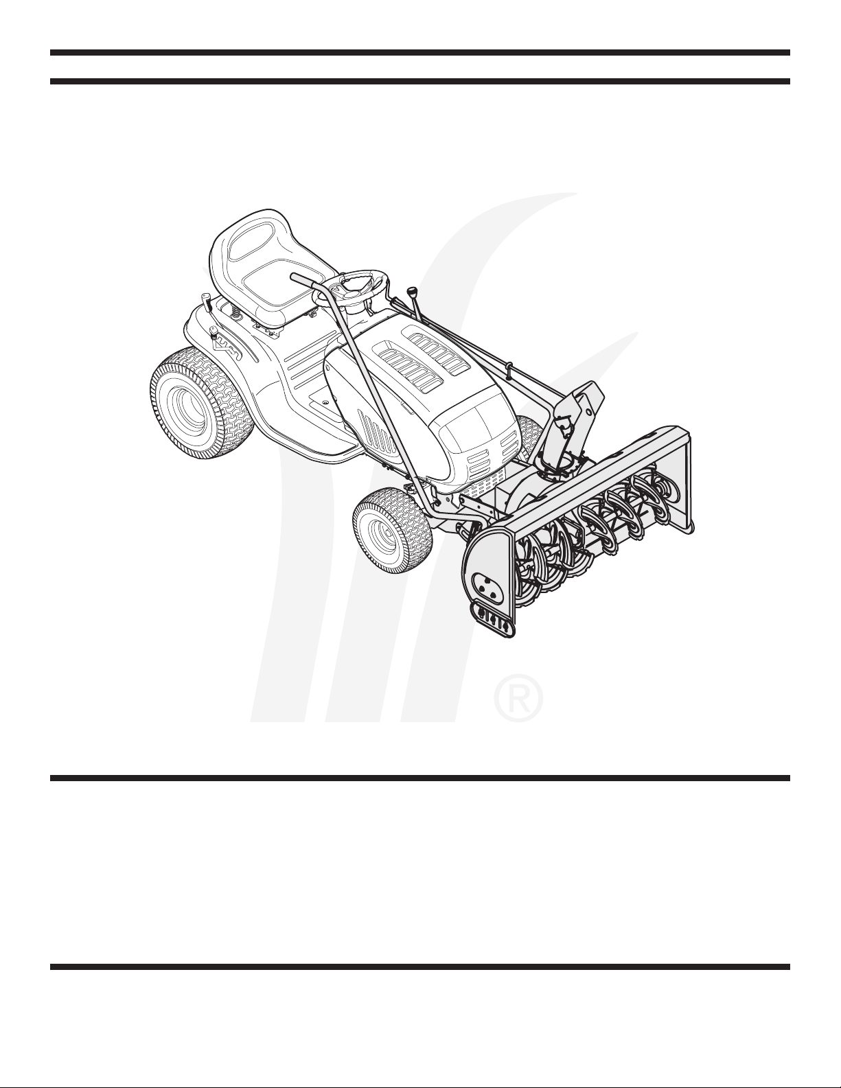
42-inch Two-Stage Snow Thrower Attachment
For FastAttach™ Compatible Lawn Tractors & Garden Tractors
IMPORTANT
READ SAFETY RULES AND INSTRUCTIONS CAREFULLY BEFORE OPERATION
Warning: This unit is equipped with an internal combustion engine and should not be used on or near any unimproved forest-covered, brush-
covered or grass-covered land unless the engine’s exhaust system is equipped with a spark arrester meeting applicable local or state laws (if any).
If a spark arrester is used, it should be maintained in effective working order by the operator. In the State of California the above is required by law
(Section 4442 of the California Public Resources Code). Other states may have similar laws. Federal laws apply on federal lands. A spark arrester
for the muffler is available through your nearest engine authorized service dealer or contact the service department, P.O. Box 361131 Cleveland,
Ohio 44136-0019.
FORM NO. 769-01933C
PRINTED IN U.S.A.
MTD LLC, P.O. BOX 361131 CLEVELAND, OHIO 44136-0019
3/8/2006
Page 2
This Operator’s Manual is an important part of your snow thrower attachment. It will help you assemble,
prepare and maintain the unit for best performance. Please read and understand what it says.
TABLE OF CONTENTS
1. Rider Model Identification ................................ Page 3
2. Snow Thrower Attachment Safety ................... Page 4-5
3. Carton Contents .............................................. Page 6-7
4. Assembly Models 600-649 & 800 Series ........ Page 8-13
5. Assembly All Model 700 Series ....................... Page 14-15
6. Attaching Controls ........................................... Page 16
7. Attaching Auger Housing ................................ Page 17
8. Routing Upper & Lower Drive Belts ................. Page 18-19
9. Controls ........................................................... Page 20
10.Operation ........................................................ Page 21
11. Adjustment
12. Maintenance ..................................................Page 23
13. Parts List ........................................................Page 24-29
13. Notes ............................................................. Page 30-31
Warranty ..........................................................Page 32
s ...................................................Page 22
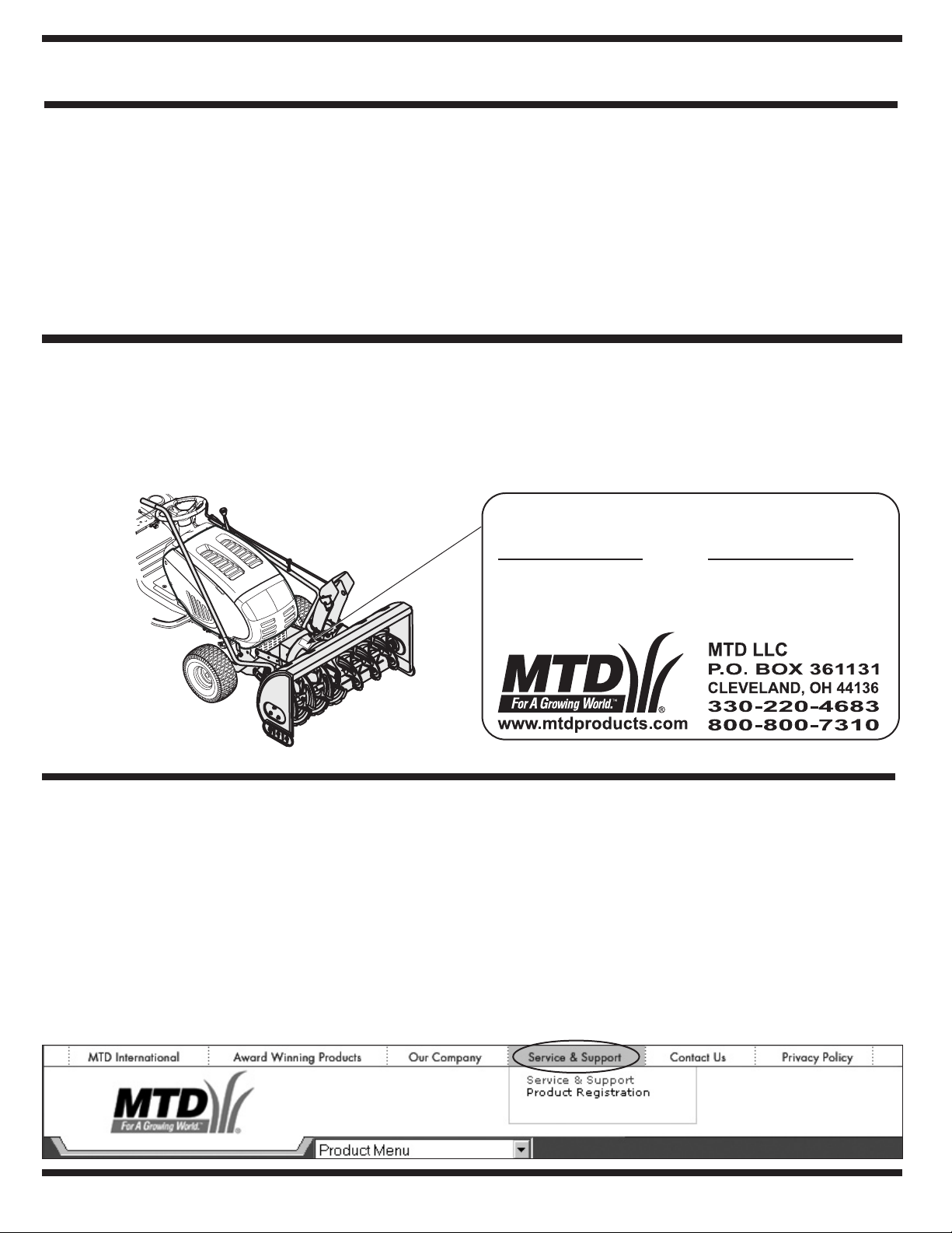
Finding and Recording Model Number
BEFORE YOU START ASSEMBLING YOUR NEW EQUIPMENT,
please locate the model plate and copy the information from it in this Operator’s Manual for future reference. The information on
the model plate is very important if you need help from our Customer Support Department or your authorized dealer. You can
locate it by looking on the top rear portion of the auger housing:
Model Number Serial Number
*Locate the model plate on your snow thrower attachment and copy the information from it in the space provided above for future reference.
Customer Support
Please do
purchased, without first contacting Customer Support.
If you have difficulty assembling this product or have any questions regarding the controls, operation, or maintenance of this
unit, you can seek help from the experts. Choose from the options below:
• Visit www.mtdproducts.com. Click on the Service & Support menu option.
• Phone a Customer Support Representative at 1-800-800-7310.
• Please have your unit’s model number and serial number ready when you call. See above to locate this information. You will
be asked to enter the serial number in order to process your call.
NOT
return the unit to the retailer from which it was
2
Page 3
Model Plate
FastAttach™ Snow
Thrower Attachment
Figure 1
Sample Model Number
1 3 A M
7 9 0
G 0 0 0
Indicates Model Series 700
NOTE: This Operator’s Manual covers several models.
1
Snow thrower hook-up instructions vary by model. Not
1
6
3
0
3
13
8
1
1
4
6
4
1
3
4
6
H
7
-
-
O
3
C
,
0
0
L
D
X
2
N
L
0
O
A
2
8
B
L
-
-
E
D
.
V
0
T
0
O
E
3
.
L
0
M
P
C
3
8
m
s
t
o
c
c
.
u
d
o
r
p
d
t
m
w
.
w
w
all features discussed in this manual are applicable to all
snow thrower attachments.
To The Owner
Rider Model
Identification
Model OEM-190-032 42-inch two-stage snow thrower
attachment is designed for use on FastAttach™ Compatible
Lawn Tractors and Garden Tractors ONLY. It will NOT fit nor
operate properly or safely on ANY other tractor.
Determine The Model
of Your Rider
Since this manual is designed for installation of your new
snow thrower attachment on several different rider units,
it is important for you to determine which model of rider
you have. Therefore you will know which set of instructions in the following pages to follow.
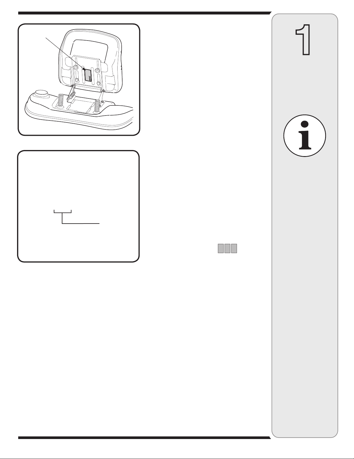
To determine which model of rider you have, you will
need to locate the rider’s model plate, located under the
seat. Simply flip the seat up and locate the model plate,
which will consist of an 11 digit/letter model number
and a serial number. For ease in this installation and
for future use, copy your rider’s model number & serial
number below now:
and RIGHT indicate the
the tractor when facing
forward in the operator’s
position. Reference to
the FRONT indicates the
grille end; to the REAR,
the rear end of the rider.
NOTE:
References to LEFT
left and right sides of
Figure
Rider Model Number:__ __ __ __ __ __ __ __ __ __ __
2
Rider Serial Number:_________________________
th
The 5
, 6th & 7th numbers from the left in your model
number determine your rider’s model series. See Figure 2.
When you fill in your model number in the space above,
the actual model series number should fall into the gray
shaded area.
Now that you have determined what model rider you
are attaching this snow thrower attachment to, follow
the instructions in the following pages according to your
model of rider. You can locate which instructions apply to
your model of rider by the gray-shaded area in the border
of each page. For instance, an 809 or 80R would signify
that you should follow the instructions for Model Series
800.
3
Page 4
WARNING: Engine Exhaust, some of its constituents, and certain vehicle components contain or emit chemicals known to State of California to cause cancer and
birth defects or other reproductive harm.
2
Safe
Operation
Practices
WARNING
This symbol points
out important safety
instructions which, if
not followed, could
endanger the personal
safety and/or property
of yourself and others.
Read and follow all
instructions in this
manual before attempting to operate
this machine. Failure
to comply with these
instructions may result
in personal injury. When
you see this symbol.
HEED ITS WARNING!
Your Responsibility
Restrict the use
of this power machine
to persons who read,
understand
and follow the warnings
and instructions
in this manual
and on the machine.
DANGER: This machine was built to be operated according to the rules for safe operation in this
manual. As with any type of power equipment, carelessness or error on the part of the operator can
result in serious injury. This machine is capable of amputating hands and feet and throwing objects.
Failure to observe the following safety instructions could result in serious injury or death.
Training
1. Read, understand, and follow all instructions on the
machine and in the manual(s) before attempting to
assemble and operate. Keep this manual in a safe place for
future and regular reference and for ordering replacement
parts.
2. Be familiar with all controls and their proper operation.
Know how to stop the machine and disengage them quickly.
3. Never allow children under 14 years old to operate this
machine. Children 14 years old and over should read and
understand the operation instructions and safety rules in
this manual and should be trained and supervised by a
parent.
4. Never allow adults to operate this machine without proper
instruction.
5. Thrown objects can cause serious personal injury. Plan
your snow-throwing pattern to avoid discharge of material
toward roads, bystanders and the like.
6. Keep bystanders, helpers, pets and children at least 75 feet
from the machine while it is in operation. Stop machine if
anyone enters the area.
7. Exercise caution to avoid slipping or falling, especially
when operating in reverse.
1. Thoroughly inspect the area where the equipment is to be
used. Remove all doormats, newspapers, sleds, boards,
wires and other foreign objects, which could be tripped over
or thrown by the auger/impeller.
2. Always wear safety glasses or eye shields during operation
and while performing an adjustment or repair to protect your
eyes. Thrown objects which ricochet can cause serious
injury to the eyes.
3. Do not operate without wearing adequate winter outer
garments. Do not wear jewelry, long scarves or other
loose clothing, which could become entangled in moving
parts. Wear footwear which will improve footing on slippery
surfaces.
4. Use a grounded three-wire extension cord and receptacle
for all units with electric start engines.
5. Adjust collector housing height to clear gravel or crushed
rock surfaces.
6. Disengage all control levers before starting the engine.
7. Never attempt to make any adjustments while engine is
running, except where specifically recommended in the
operator’s manual.
8. Let engine and machine adjust to outdoor temperature
before starting to clear snow.
9. To avoid personal injury or property damage use extreme
care in handling gasoline. Gasoline is extremely flammable
and the vapors are explosive. Serious personal injury can
occur when gasoline is spilled on yourself or your clothes,
which can ignite. Wash your skin and change clothes
immediately.
a. Use only an approved gasoline container.
b. Extinguish all cigarettes, cigars, pipes and other sources
of ignition.
c. Never fuel machine indoors.
d. Never remove gas cap or add fuel while the engine is hot
or running.
e. Allow engine to cool at least two minutes before refuel
ing.
f. Never over fill fuel tank. Fill tank to no more than ½ inch
below bottom of filler neck to provide space for fuel
expansion.
g. Replace gasoline cap and tighten securely.
h. If gasoline is spilled, wipe it off the engine and equip
ment. Move machine to another area. Wait 5 minutes
before starting the engine.
i. Never store the machine or fuel container inside where
there is an open flame, spark or pilot light (e.g. furnace,
water heater, space heater, clothes dryer etc.).
j. Allow machine to cool at least 5 minutes before storing.
Preparation
-
-
4
Page 5

Operation
1. Do not put hands or feet near rotating parts, in the
auger/impeller housing or chute assembly. Contact with the
rotating parts can amputate hands and feet.
2. The auger/ impeller control lever is a safety device. Never
bypass its operation. Doing so makes the machine unsafe
and may cause personal injury.
3. The control levers must operate easily in both directions
and automatically return to the disengaged position when
released.
4. Never operate with a missing or damaged chute assembly.
Keep all safety devices in place and working.
5. Never run an engine indoors or in a poorly ventilated area.
Engine exhaust contains carbon monoxide, an odorless and
deadly gas.
6. Do not operate machine while under the influence of alcohol
or drugs.
7. Muffler and engine become hot and can cause a burn. Do
not touch.
8. Exercise extreme caution when operating on or crossing
gravel surfaces. Stay alert for hidden hazards or traffic.
9. Exercise caution when changing direction and while operat
ing on slopes.
10. Plan your snow-throwing pattern to avoid discharge towards
windows, walls, cars etc. Thus, avoiding possible property
damage or personal injury caused by a ricochet.
11. Never direct discharge at children, bystanders and pets or
allow anyone in front of the machine.
12. Do not overload machine capacity by attempting to clear
snow at too fast of a rate.
13. Never operate this machine without good visibility or light.
Always be sure of your footing and keep a firm hold on the
handles. Walk, never run.
14. Disengage power to the auger/impeller when transporting or
not in use.
15. Never operate machine at high transport speeds on slippery
surfaces. Look down and behind and use care when
backing up.
16. If the machine should start to vibrate abnormally, stop the
engine, disconnect the spark plug wire and ground it against
the engine. Inspect thoroughly for damage. Repair any
damage before starting and operating.
17. Disengage all control levers and stop engine before you
leave the operating position (behind the handles). Wait
until the auger/impeller comes to a complete stop before
unclogging the chute assembly, making any adjustments, or
inspections.
18. Never put your hand in the discharge or collector openings.
Always use the clean-out tool provided to unclog the dis
charge opening. Do not unclog chute assembly while engine
is running. Shut off engine and remain behind handles until
all moving parts have stopped before unclogging.
19. Use only attachments and accessories approved by the
manufacturer (e.g. wheel weights, tire chains, cabs etc.).
20. If situations occur which are not covered in this manual,
use care and good judgment. Contact your dealer or call
(800) 800-7310 for assistance and the name of your nearest
servicing dealer..
-
Maintenance & Storage
1. Never tamper with safety devices. Check their proper
operation regularly. Refer to the maintenance and adjust
ment sections of this manual.
2. Before cleaning, repairing, or inspecting machine disen
gage all control levers and stop the engine. Wait until the
auger/impeller come to a complete stop. Disconnect the
spark plug wire and ground against the engine to prevent
unintended starting.
3. Check bolts and screws for proper tightness at frequent
intervals to keep the machine in safe working condition.
Also, visually inspect machine for any damage.
4. Do not change the engine governor setting or over-speed
the engine. The governor controls the maximum safe
operating speed of the engine.
5. Snow thrower shave plates and skid shoes are subject to
wear and damage. For your safety protection, frequently
check all components and replace with original equipment
manufacturer’s (OEM) parts only. “Use of parts which do
not meet the original equipment specifications may lead to
improper performance and compromise safety ! ”
6. Check controls periodically to verify they engage and
disengage properly and adjust, if necessary. Refer to the
adjustment section in this operator’s manual for instructions.
7. Maintain or replace safety and instruction labels, as neces
sary.
8. Observe proper disposal laws and regulations for gas, oil,
etc. to protect the environment.
9. Prior to storing, run machine a few minutes to clear snow
from machine and prevent freeze up of auger/impeller.
10. Never store the machine or fuel container inside where
there is an open flame, spark or pilot light such as a water
heater, furnace, clothes dryer etc.
11. Always refer to the operator’s manual for proper instructions
on off-season storage.
Do not modify engine
To avoid serious injury or death, do not modify engine in any
way. Tampering with the governor setting can lead to a runaway
engine and cause it to operate at unsafe speeds. Never tamper
with factory setting of engine governor.
Notice regarding Emissions
Engines which are certified to comply with California and federal
EPA emission regulations for SORE (Small Off Road Equipment)
are certified to operate on regular unleaded gasoline, and may
include the following emission control systems: Engine Modifica
tion (EM) and Three Way Catalyst (TWC) if so equipped.
Your Responsibility
Restrict the use of this power machine to persons who read, understand and follow the warnings and instructions in this manual
and on the machine.
-
-
2
Safe
Operation
Practices
WARNING
-
This symbol points
out important safety
instructions, which if
not followed, could
endanger the personal
safety and/or property
of yourself and others.
Read and follow all
instructions in this manual before attempting to
operate this machine.
Failure to comply with
these instructions may
result in personal injury.
When you see this
-
symbol.
HEED IT’S WARNING!
Your Responsibility
Restrict the use
of this power machine
to persons who read,
understand
and follow the warnings
and instructions
in this manual
and on the machine.
5
Page 6
3
Carton
Self-Adhesive
Reflectors
Extension Spring
Idler Assembly
Belt Keeper & Hardware
Contents
If you are missing
any parts, please
do not contact the
retailer where you
purchased this unit,
call MTD directly at
1-330-220-4MTD or
toll free at
1-800-800-7310.
Extension Spring
Wing Nut
Upper V-Belt
(754-0490)
Idler Pulley & Pin
Belt Keeper
& Hardware
Assembl
& Hardware
y Brackets
Undercarriage Assembly
Cable Ties
Clamp
Cotter Pin
Chute Directional
Support w/ Tilt Lever
& Upper Crank Rod
Upper V-Belt
(754-0481)
Upper V-Belt
(754-0498)
Upper V-Belt
(754-0435)
Lift Handle
Assembl
y
Auger Housing
Assembl
Linkage
y w/
6
k Pins &
Clic
Clevis Pins
Spare Shear Bolts
x Lock Nuts
& He
Page 7

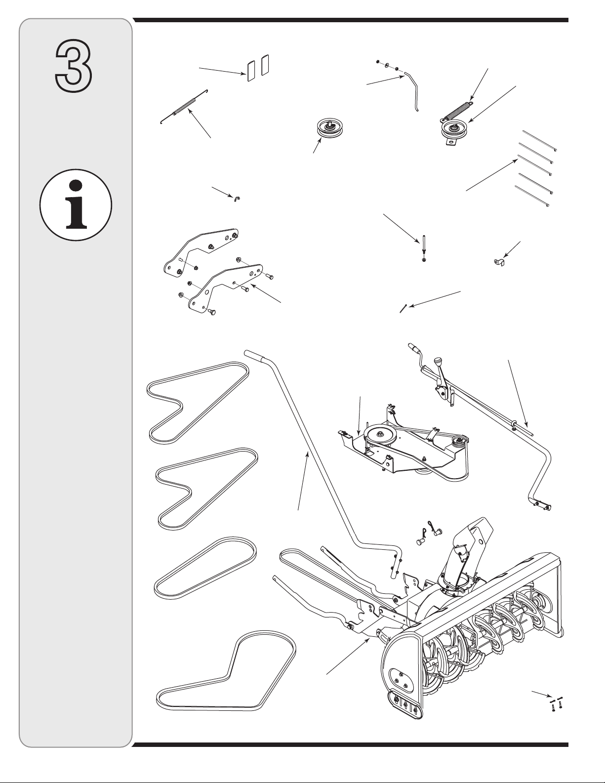
CONTENTS OF CARTON
Before beginning installation, remove all parts from the carton to make sure everything is present. Carton
contents are listed below and shown in Figure 3. Hardware part numbers are shown in parentheses.
• One Auger Housing Assembly w/ Lower V-belt
• One Undercarriage Assembly (w/ Upper V-belt 754-0371A)
• One Idler Assembly w/ Extension Spring (732-0594A)
• One Idler Pulley (756-0627B) and Pin (650-0040) w/ Hair Pin Clip (714-0145)
• One Belt Keeper (747-04135) w/ Bell Washer (736-0270) Jam Nut (712-0298) & Hex Nut (712-3006)
• One Lift Handle Assembly
• One Upper Chute Crank Rod
• One Chute Directional Support w / Tilt Lever
• Five Cable Ties (725-0157)
• Two Spare Shear Pins (738-04124) & Cotter Pins (714-04040)
• One Cotter Pin (714-0507)
• Two Self-adhesive Reflectors (730-3000)
• One Upper V-belt (754-0481)
• One Upper V-belt (754-0435)
• One Upper V-belt (754-0490)
• One Upper V-belt (754-0498)
• Left & Right Assembly Brackets (683-04215 & 683-04214) & Hardware (710-0514 Hex Screw, 712-04065
Flange Nut, 738-0143 Shoulder Screw & 712-04063 Flange Nut)
• Belt Keeper (711-1000) & Flange Lock Nut (712-04063 )
• Wing Nut (712-04100)
• 16mm Clamp (726-0354)
• Extension Spring (732-04237)
• Clevis Pin (711-0332)
• Click Pin (714-0145)
3
Carton
Contents
If you are missing
any parts, please
do not contact the
retailer where you
purchased this unit,
call MTD directly at
1-330-220-4MTD
or toll free at
1-800-800-7310.
7
Page 8
4
WARNING: Before installing attachment, place tractor on a firm and level
surface. Place the PTO in the disengaged (OFF) position, set the parking
brake, shut engine off and remove key
to prevent unintended starting.
Assembly
Model Series
600-649 &
All 800 series.
WARNING
Before installing
attachment, place
tractor on a firm
and level surface.
Place the PTO in
the disengaged
(OFF) position, set
the parking brake,
shut engine off and
remove key to prevent
unintended starting.
NOTE: References to LEFT and RIGHT indicate the left
and right sides of the tractor when facing forward in the
operator’s position. Reference to the FRONT indicates
the grille end; to the REAR the drawbar end.
IMPORTANT: You must first figure out which model of
rider you are attaching this snow thrower to. Refer to
Determine Your Model of Rider on page 3 of this manual
to determine what model rider you are attempting to
install this attachment to. Then proceed to the applicable
instructions for your model of rider.
Your tractor’s cutting deck, PTO belt and front deck
stabilizer bracket must be removed prior to mounting
the snow thrower attachment. Refer to your tractor’s
Operator’s Manual for detailed instructions. If your
tractor is equipped with any front-end accessory (i.e.
front bumper kit), it must also be removed.
Mounting the
Idler Pulley and Pin
(Manual PTO Tractors equipped with
a 38- or 42-inch deck ONLY)
Frame Mount Dual Idler Style 2004 & Prior
NOTE: If you engage your tractor’s cutting deck by
using your left hand to pivot a lever forward, your tractor
has a Manual PTO. If you engage your tractor’s cutting
deck by pulling outward on a small knob located on the
tractor’s dash, your tractor has an Electric PTO.
The idler pulley and pin (packaged separately, refer to
pages 6-7) must be installed to the PTO engagement
plate of all manual PTO tractors with a dual-belt drive
38- or 42-inch cutting deck. If applicable, proceed as
follows. Otherwise, proceed to Mounting the Under-
carriage Assembly.
Locate the PTO engagement plate beneath your tractor.
See Figure 4.
Note the location of the weld pin on the rear portion of
the PTO engagement plate. This pin is where the deck
brake cable attaches, when operating the tractor with
the cutting deck mounted.
Remove the hair pin clip from the idler pulley and pin
(packaged separately). Refer to pages 6-7.
Position the idler pulley and pin onto the weld pin of the
PTO engagement plate and secure with the hairpin clip
just removed.
NOTE: This Idler pulley must be removed when
remounting the tractor’s cutting deck.
Weld Pin Tractor Frame
PTO Engagement Plate
Figure 4
8
Page 9

Flange Nut, Washer &
Shoulder Spacer
Double-idler Bracket/Front Pulley
Figure 5
Undercarriage
Shoulder Spacer
(Facing Up)
Flat Washer
Flange Nut
Figure 6
3-in. Hex Bolt
Spacers
Shoulder Spacer
(Facing Down)
Reversing the
Idler Assembly Hardware
(Manual PTO Garden Tractors
equipped with a 46-inch deck ONLY)
If you’re mounting this snow thrower attachment to a
tractor equipped with any deck other than a manually
engaged 46-inch, proceed to either:
1. Mounting the Idler Assembly (for tractors equipped
with a 42, 46, 50 & 54-inch deck ONLY) in this
section
2. Mounting the Idler Pulley and Pin (for Manual PTO
tractors equipped with a 38- or 42-inch deck ONLY)
previously in this section, or
3. Mounting the Undercarriage Assembly (all
tractors not mentioned above) on page 12.
These instructions are for mounting this snow thrower
attachment to a GARDEN TRACTOR (Model Series
800) equipped with a Manual PTO and a 46-inch deck.
NOTE: If you own a Manual PTO Lawn Tractor with
a 46-inch deck, you can disregard the following steps;
they are unnecessary. A LAWN TRACTOR is any 600649 Series mower, an 800 Series mower is a GARDEN
TRACTOR. Refer to Determine Your Model of Rider
on page 3 of this manual to determine what model rider
you are attempting to install this attachment to.
1. Remove the flange nut, washer and shoulder
spacer which secures the double-idler bracket to the
undercarriage. See Figure 5.
2. Remove the 3-inch hex bolt from the bottom of the
front pulley, to free it from the undercarriage.
3. Reassemble with the 3-inch hex bolt on top of the
undercarriage and the flange nut securing the pulley
from the bottom. See Figure 6.
IMPORTANT: Components must be reassembled in the
exact order illustrated in Figure 6.
4
Assembly
Model Series
600-649 &
All 800 series.
WARNING
Before installing
attachment, place
tractor on a firm
and level surface.
Place the PTO in
the disengaged
(OFF) position, set
the parking brake,
shut engine off and
remove key to prevent
unintended starting.
Bell Washer
Jam Nut
Figure 7
Mounting the Belt Keeper
(Manual PTO Garden Tractors equipped
with a 46-inch deck ONLY)
The belt keeper and hardware (packaged separately,
refer to page 6-7) must be installed around the engine
pulley of all Manual PTO Garden Tractors with a 46-inch
cutting deck. To do so, proceed as follows:
1. Locate the engine pulley by looking beneath the front
area of your tractor.
2. Secure the belt keeper to the inside of the tractor’s
frame with the hex nut, bell washer and jam nut as
shown in Figure 7.
3. Make certain the cupped portion of the bell washer is
facing IN before tightening the jam nut.
9
Page 10
4
Assembly
Model Series
600-649 &
All 800 series
Cub Cadet
11C & 13C
WARNING
Before installing
attachment, place
tractor on a firm
and level surface.
Place the PTO in
the disengaged
(OFF) position, set
the parking brake,
shut engine off and
remove key to prevent
unintended starting.
Mounting the Idler Assembly
(42, 46, 50, 54 inch Decks
with Electric PTO)
If you’re mounting this snow thrower attachment to a
tractor equipped with any deck other than a 42, 46, 50
or 54-inch deck with electric PTO, proceed to Mounting
the Undercarriage Assembly (all tractors) .
However, if you’re mounting this snow thrower attachment to a tractor equipped with a 42, 46, 50 or 54-inch
deck with electric PTO, proceed as follows:
NOTE: If you engage your tractor’s cutting deck by
using your left hand to pivot a lever forward, your tractor
has a Manual PTO. If you engage your tractor’s cutting
deck by pulling outward on a small knob located on the
tractor’s dash, your tractor has an Electric PTO.
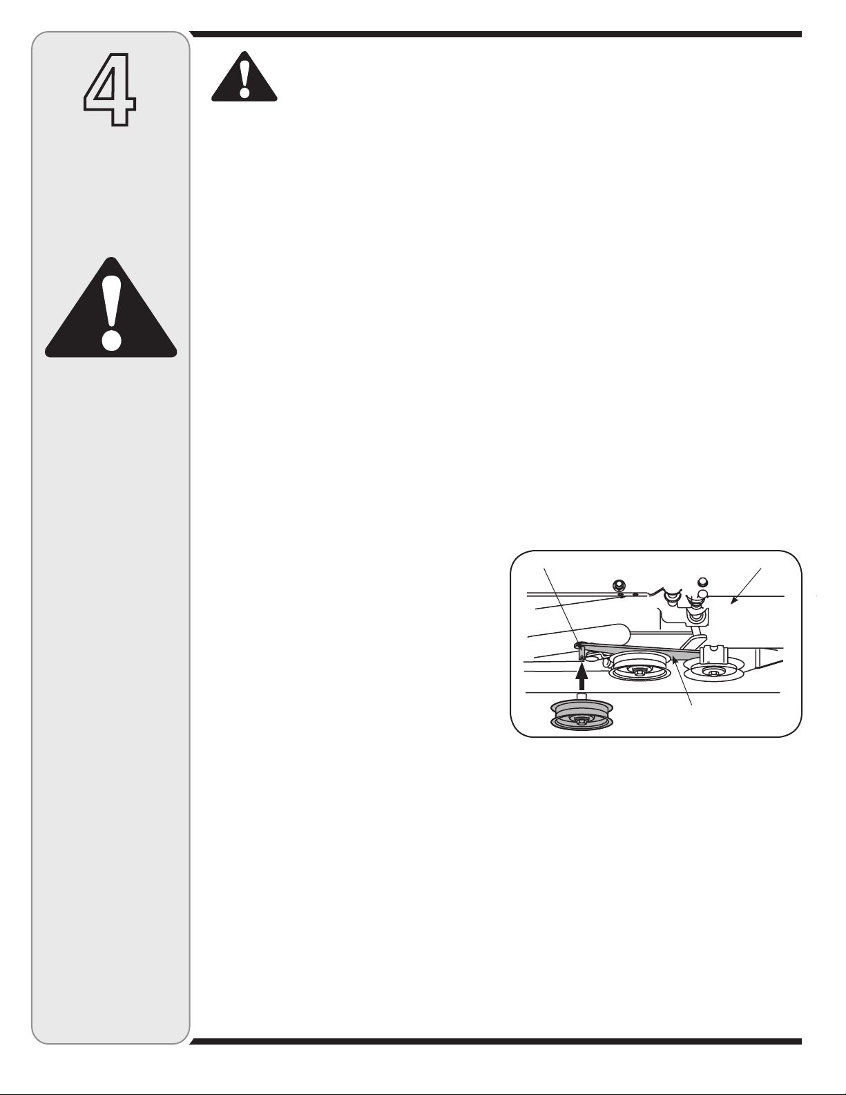
1. Remove the flange nut and washer noted in Figure
8, which secures the double-idler bracket to the
undercarriage. Leave the Shoulder Spacer in place.
2. Attach the idler assembly (packaged separately)
over the hex screw and shoulder spacer on the
surface of the undercarriage. See Figure 8.
3. Fasten the idler bracket to the undercarriage with the
hardware just removed. See Figure 8.
4. Attach one end of the extension spring (732-0594A)
to the hole in the idler assembly just mounted and
the opposite end of the extension spring to the
keeper pin as illustrated in Figure 8.
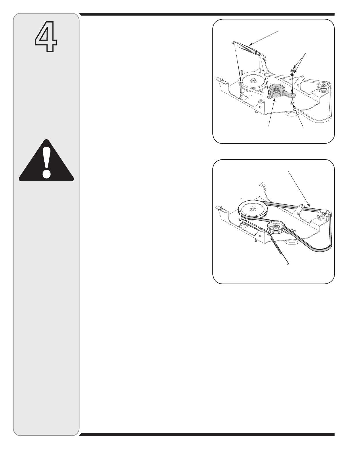
5. Position the upper v-belt (754-0371A) as illustrated
in Figure 9.
NOTE: For a complete detailed diagram of how to route
the upper v-belt, see Routing The Upper Drive Belt
beginning at the top of page 18.
NOTE: Proceed to the top of page 12 for continued
installation instructions for the 600, 800, 11C & 13C
model series.
Idler Bracket & Pulley
Upper V-belt (754-0371A)
Extension Spring
Flange Lock Nut
& Flat Washer
Shoulder Spacer
Figure 8
Figure 9
10
Page 11

PTO Cable
Slotted
Fitting
Threaded Pin
Click Pins
Clevis Pins
Spindle Pulley
Extension Spring
Belt Keeper Pin
Flange Lock
Nut & Washer
Idler Pulley &
Idler Bracket
Figure 10a
V-Belt
Undercarriage Assembly
Figure 10b
Belt Keeper
Pin
V-Belt
Figure 11
Undercarriage Assembly
1. Remove the v-belt (754-0371A), this belt will be
replaced later with another v-belt (754-0498) included
in this carton. Also, remove all of the Clevis Pins and
Click pins as seen in Figure 10b.
2. Remove
out in Figure 10a, leaving the spacer underneath it in
place. Mount the idler pulley (756-0627D) and idler
bracket (783-1291) from the loose parts included in
this carton. Replace the flange lock nut and washer.
3. Locate
spring (Part No. 732-04237, which is .50” wide x 12”
long) packaged with the loose parts in this carton.
See Figure 11 for reference.
NOTE:
embossed on the outside of the belt.
Route the belt around the spindle pulley, inside of
the belt keepers and to the inside of the idler pulley.
The spring will connect to the Idler bracket but you
may install this once the undercarriage is mounted.
Otherwise it could fall off or get in the way in the
following steps. If you wish to connect this later, retain
the spring for later installation. See the Figure 11.
4. Attach the PTO cable to the idler bracket, then fit the
cable into the slotted fitting as seen in Figure 10a
NOTE: The PTO cable should be hanging down under
you tractor after you removed the mowing deck. You
will need to slide the undercarriage unit under your trac
tor in position for which it will be mounted. The slanted
side should be pointed towards the front of your tractor.
Mounting Undercarriage Assembly
Make certain the correct upper drive belt (754-0498) is
installed on the undercarriage assembly. If the appropri
ate belt is not installed, replace it with the correct belt
prior to proceeding with mounting the undercarriage.
IMPORTANT: Make certain that the flat side of the belt
is facing outward as it sits against both the idler pulley
and spindle pulley. This allows the “V” side of the belt to
ride snugly in both pulleys.
1. The undercarriage assembly should be in position
beneath the tractor, since you already connected the
PTO cable in the previous steps.
2. There should already be a threaded pin installed in one
of the mounting holes of the undercarriage assembly. If
not installed, install it now as in Figure 10b.
Lift the undercarriage assembly up, inserting the
weld pins on the assembly up through the aligning
holes found along the tractor’s frame rails. Fasten
with hairpin clips and flat washers removed earlier.
See inset image in Figure 11.
3. Connect the extension spring found in your units
loose parts that was mentioned earlier. This spring
connects to the idler bracket on the undercarriage
assemble and the hole on the rear right-hand snow
thrower mounting bracket. See Figure 11.
4. Attach the lower auger drive belt by routing it around
and through the pulley system as seen in Figure 11
NOTE: Proceed to page 16 for next installation steps.
the flange lock nut and washer as pointed
v-belt part No. 754-0498 and the extension
The V-belt can be identified by the part number
.
.
4
Assembly
Model Series
600-649 &
Cub Cadet 11C
(38 & 42-inch
Decks with
Cable-Drive PTO)
Deck Idler/
Pull Style
2005 & Later
-
WARNING
Before installing
-
attachment, place
tractor on a firm
and level surface.
Place the PTO in
the disengaged
(OFF) position, set
the parking brake,
shut engine off and
remove key to prevent
unintended starting.
NOTE:
Proper belt routing
diagrams can be
found on page 18-19
of this manual.
11
Page 12

4
Assembly
Model Series
600-649 &
All 800 series
Cub Cadet
11C & 13C
WARNING
Before installing
attachment, place
tractor on a firm
and level surface.
Place the PTO in
the disengaged
(OFF) position, set
the parking brake,
shut engine off and
remove key to prevent
unintended starting.
Because this snow thrower attachment is compatible
with several model lawn tractors and garden tractors
with either an electric PTO or a manual PTO, four upper
drive belts are included. If you have had any problems
locating the proper upper belts for installation in the
previous steps, use the table below for quick reference.
Refer to the table below to determine which upper drive
belt is applicable to your tractor; non-applicable belts
can be discarded. The v-belt can be identified by the
part number embossed on the outside of the belt.
Upper Drive Belt Reference Chart
Deck Size Electric PTO Manual PTO
54-in. Deck 754-0371A N/A
50-in. Deck 754-0371A 754-0481
46-in. Deck 754-0371A 754-0490
(Garden Tractor)
46-in. Deck 754-0371A 754-0481
(Lawn Tractor)
42-in. Deck 754-0371A 754-0481
(single-belt drive)
42-in. Deck 754-0371A 754-0435
(dual-belt drive)
38-in Deck N/A 754-0435
(dual-belt drive)
NOTE: If you engage your tractor’s cutting deck by
using your left hand to pivot a lever forward, your tractor
has a Manual PTO. If you engage your tractor’s cutting
deck by pulling outward on a small knob located on the
tractor’s dash, your tractor has an Electric PTO.
Mounting The
Undercarriage Assembly
(All 600-649 & 800 Model Series Tractors)
1. Remove and retain the four hairpin clips from the weld
pins found the top side of the undercarriage assembly,
and also the 4 clevis pins with hairpin clips. Retain
this hardware for later installation. See Figure 12
IMPORTANT: Make certain the correct upper drive
belt is installed on the undercarriage assembly prior to
proceeding with mounting the undercarriage. Make sure
that the upper v-belt is routed to the INSIDE of the belt
keeper found on the undercarriage idler pulley and the
keeper pins found around the spindle pulley. Also, make
certain that the flat side of the belt is facing outward.
2. Position the undercarriage assembly beneath the
tractor. For manual PTO units, hook up the PTO
cable as described earlier in this section
3. Move the tractor’s deck lift lever into the lowest notch
on the fender allowing the lift arms to drop. See
Figure 13.
.
.
V-Belt
Click Pins
Belt Keeper
Clevis Pins
Undercarriage Assembly
Figure 12
Deck Lift
Lever
Lift Arm
Figure 13
12
Page 13

Lift Arm
Clevis Pin
Figure 14
Spring Attached
to Idler Pulley
4. Align the holes in the rear of the lift arms with the
holes in the rear of the undercarriage and insert the
clevis pins removed in step 1. Fasten with the hairpin
clips. See Figure 14.
5. Move the tractor’s deck lift lever into the top notch on
the right fender allowing the lift arms and the rear of
the undercarriage assembly to rise.
6. Insert the weldpins found on the top side of the rear
portion of the undercarriage assembly up through the
aligning holes found along the tractor’s frame rail. See
Figure 15.
7. Fasten with the hairpin clips removed in step 1.
8. Repeat the previous two steps on the front portion of
the undercarriage assembly.
9. Connect the extension spring to the tractor’s frame rail
in the hole provided. See Figure 16.
NOTE: The other end of the spring is attached to the
idler pulley. For an example of where this spring should
attach, see Figure 14.
NOTE: Refer to the Routing the Upper Drive Belt
section of this manual (Page 18) for proper upper drive
belt installation instructions. Routing The Lower Drive
Belt instructions can also be found in that section.
4
Assembly
Model Series
600-649 &
All 800 series
Cub Cadet
11C & 13C
WARNING
Figure 15
Figure 16
Before installing
attachment, place
tractor on a firm
and level surface.
Place the PTO in
the disengaged
(OFF) position, set
the parking brake,
shut engine off and
remove key to prevent
unintended starting.
13
Page 14

5
Bracket &
Undercarriage
Assembly
Model Series
700-799
WARNING
Before installing
attachment, place
tractor on a firm
and level surface.
Place the PTO in
the disengaged
(OFF) position, set
the parking brake,
shut engine off and
remove key to prevent
unintended starting.
Bracket Assembly
WARNING: Before installing attachment, place tractor on a firm and level
surface. Place the PTO in the disengaged (OFF) position, set the parking
brake, shut engine off and remove key
to prevent unintended starting.
NOTE: Your tractor’s cutting deck, PTO belt and
front deck stabilizer bracket must be removed prior to
mounting the snow thrower attachment. Refer to your
tractor’s Operator’s Manual for detailed instructions. If
your tractor is equipped with any front-end accessory
(i.e. front bumper kit), it must also be removed.
1. Install a shoulder screw (738-0143) and flange lock
nut (712-04065) in the top front hole of each snow
thrower assembly bracket as in Figure 17.
2. Mount snow thrower assembly brackets (683-04214
& 683-04215) to your tractor using the loose
hardware included (Hex Screw 710-0514 & Flange
Lock Nut 712-04065). See Figure 17.
NOTE: Remove the wiring harness from tractor frame
(left side only) and mount on the outside of the assembly
bracket using the clamp (726-0354) included with your
hardware pack.
Undercarriage Assembly
1. Remove the threaded pin, click pins and clevis pins
from your undercarriage assembly and retain for
installation later. Also, remove the v-belt (754-0371A),
this belt will be replaced later with another v-belt
(754-0498) included in this carton. See Figure 18.
2. Remove the flange lock nut and flat washer as
pointed out in Figure 19, leaving the spacer underneath it in place. Mount the idler pulley (756-0627D)
and idler bracket (783-1291) from the loose parts
included in this carton. Replace the nut and washer.
3. Attach the PTO cable to the idler bracket, then fit the
cable into the slotted fitting as seen in Figure 19.
NOTE: The PTO cable should be hanging down under
you tractor after you removed the mowing deck. You
will need to slide the undercarriage unit under your tractor in position for which it will be mounted. The slanted
side should be pointed towards the front of your tractor.
4. Locate v-belt part No. 754-0498 and the extension
spring (Part No. 732-04237, which is .50” wide x 12”
long) packaged with the loose parts in this carton.
NOTE: The V-belt can be identified by the part number
embossed on the outside of the belt.
5. Route the belt around the spindle pulley, inside of
the belt keepers and to the inside of the idler pulley.
The spring will connect to the Idler bracket but you
may install this once the undercarriage is mounted.
Otherwise it could fall off or get in the way in the
following steps. If you wish to connect this later,
retain the spring for later installation. See the Figure
20 illustration on the following page.
Wiring Harness
Clamp
NOTE: Left
side view
Hex Screws
Shoulder
Screw
Threaded Pin
Clevis Pins
PTO Cable
Slotted
Fitting
Flange
Lock
Nuts
Figure 17
V-Belt
Undercarriage Assembly
Figure 18
Belt Keeper Pin
Flange Lock
Nut & Washer
Idler Pulley &
Idler Bracket
Figure 19
14
Page 15

Spindle Pulley
Belt Keeper
Pin
6. Install the additional belt keeper pin and hardware
included with the loose parts in this carton. See
Figure 19 for belt keeper location placement.
Extension Spring
Remove Nut
V-Belt
Figure 20
Figure 21
A B
Figure 22
Hairpin Clip
Mounting the Undercarriage
Assembly
Make certain the correct upper drive belt (754-0498) is
installed on the undercarriage assembly. If the appropriate belt is not installed, replace it with the correct belt
prior to proceeding with mounting the undercarriage.
IMPORTANT: Make certain that the flat side of the belt
is facing outward as it sits against both the idler pulley
and spindle pulley. This allows the “V” side of the belt to
ride snugly in both pulleys.
1. The undercarriage assembly should be in position
beneath the tractor, since you already connected the
PTO cable in the previous steps.
2. Remove the nut from the rear undercarriage mounting stud located on the tractors frame rail on the right
side of the tractor. See Figure 21.
3. Lift the undercarriage assembly up, inserting the
weld pins on the assembly up through the aligning
holes found along the tractor’s frame rails. Fasten
with hairpin clips and flat washers removed earlier.
See B in Figure 22.
The rear hole on the right side will fit over the stud
already installed on your tractor. Fasten with the
wing nut (included with your hardware pack) and flat
washer removed earlier. See A in Figure 22.
4. Connect the extension spring found in your units
loose parts that was mentioned earlier. This spring
connects to the idler bracket on the undercarriage
assemble and the hole on the rear right-hand snow
thrower mounting bracket. See Figure 23.
5. Attach the lower auger drive belt by routing it around
and through the pulley system as seen in Figure 23.
NOTE: Proper belt routing diagrams can be found on
page 18-19 of this manual.
5
Bracket &
Undercarriage
Assembly
Model Series
700-799
WARNING
Before installing
attachment, place
tractor on a firm and
level surface. Place the
PTO in the disengaged
(OFF) position, set
the parking brake,
shut engine off and
remove key to prevent
unintended starting.
IMPORTANT:
Make certain that the flat
side of the belt is facing
outward as it sits against
both the idler pulley
and spindle pulley. This
allows the “V” side of the
belt to ride snugly in
both pulleys.
Figure 23
15
Page 16

Upper Chute
Crank Rod
6
Assembling
Controls
All Models
NOTE:
All references to left
or right side of the
snow thrower is
from the operating
position only.
Joint Block
Lower Chute
Crank Rod
B
Attaching the Chute
Directional Control
1. Secure the upper chute crank rod to the joint block
(A) on the lower chute crank rod with the cotter pin
(B) provided. See Figure 24.
2. Attach the chute directional control assembly to the
upper lift link on the left side of the auger housing
assembly with two hex screws as illustrated in Figure
25. Secure with two flange nuts.
3. Fasten the chute tilt cables to the chute directional
control with two of the cable ties provided. Pull the
cable ties until they’re snug and trim off excess.
A
Chute Directional
Control Assembly
Figure 24
Attaching The
Lift Handle
1. Attach the lift handle to the lift bracket on the right
side of the auger housing assembly with the two hex
screws and two flange nuts provided. See Figure 26.
2. Fasten the lift cable to the lift handle with two of the
cable ties provided. Pull the cable ties until they’re
snug and trim off any excess.
Lift Handle
Upper Lift Link
Figure 25
Chute Directional
Control Assembly
Auger Housing Assembly
Figure 26
Attaching the Reflectors
Peel off the backing from each of the reflectors to expose
the adhesive surface. Adhere the reflectors to the rear of
the tractor’s fender (one on the left and one on the right)
so that the reflectors simulate taillights.
16
Page 17

Inset B
Figure 27
Mounting Auger Assembly
1. Position the auger housing assembly in front of the tractor
as seen in Figure 27. Lay the belt and support tubes out as
seen above.
IMPORTANT: If you are installing this snow thrower
attachment on any mower model with a letter designation
(i.e. 60R or 80R, 80T, etc.) then the heat shield on the
auger housing must be removed. Do not remove this heat
shield on any other model of mower. To determine your
model number, see page 2-3 of this manual.
IMPORTANT: It will be necessary to have a second
person assist you to complete the following steps.
2. Carefully move the tractor forward (by
pushing, NOT driving it) so that the support
tubes found on the rear of the auger hous
ing assembly are positioned between the
tractor’s front tires. Set the parking brake.
WARNING: Before installing attachment, place tractor on a firm and level surface. Place
the PTO in the disengaged (OFF) position, set the
parking brake, shut engine off and remove key to
prevent unintended starting.
3. With the help of an assistant, lift up the auger housing
up and move the attachment back aligning the hooks
found on the rear of the lift assembly over the shoulder
bolts found on both the left and the right sides of the
tractor’s front pivot support brackets. See Figure 27
Inset A.
Inset A
4. Maneuver the auger housing until the mounting holes
lineup. Insert a clevis pin from your hardware pack
and secure with a click pin, into the tractor’s front pivot
support brackets seen in Figure 27 Inset B.
5. Repeat Step 4 on the left side, inserting a clevis pin
secured with a click pin.
Attaching the Support
Tubes
1. Secure the right support tube to the front of the
undercarriage assembly with the clevis pin and
hairpin clip removed earlier. See Figure 28.
2. Repeat the previous step on the left side.
-
Figure 28
7
Mounting
Auger
Housing
All Models
WARNING
Before installing
attachment, place
tractor on a firm and
level surface. Place
the PTO in the disengaged (OFF) position,
set the parking brake,
shut engine off and
remove key to prevent
unintended starting.
17
Page 18

Routing the Upper Drive Belt (Tractors Models with an Electric PTO)
8
Belt
Routing
Various Models
WARNING
Before installing
attachment, place
tractor on a firm and
level surface. Place
the PTO in the disengaged (OFF) position,
set the parking brake,
shut engine off and
remove key to prevent
unintended starting.
Spindle Pulley
Idler Pulley
Engine Pulley
All electric PTO
Decks 42, 46, 50, 54
PTO Idler Pulley
Figure 29
1. Attach and route the upper drive belt around the spindle pulley and idler pulley found on the undercarriage, the
electric PTO clutch and the PTO idler pulley as illustrated in Figure 29. Make sure that the belt is routed to the
INSIDE of the belt keeper on the undercarriage idler pulley and the remaining keeper pins found around the
spindle pulley.
IMPORTANT: Make certain that the flat side of the belt is facing outward as it sits against both the electric PTO
clutch and spindle pulley. This allows the “V” side of the belt to ride snugly in both pulleys.
Routing the Upper Drive Belt (Tractor Models 700 Series; and 600 Series 2005 &
newer cable drive PTO)
Spindle Pulley Engine Pulley
All Manual PTO
Decks 38 & 42
IMPORTANT:
Make certain that the
flat side of the belt is
facing outward. This
allows the “V” side of
the belt to ride snugly
in both pulleys.
PTO Idler Pulley
Figure 30
1. Attach and route the upper drive belt around the engine pulley and spindle pulley, routed to the INSIDE of the
PTO idler pulley on the undercarriage. Make sure the belt is routed inside of the belt keeper pins found around
the spindle pulley and engine pulley. See Figure 30.
IMPORTANT: Make certain that the flat side of the belt is facing outward. This allows the “V” side of the belt to ride
snugly in both pulleys.
18
Page 19

Routing the Upper Drive Belt (Older Style Tractors )
8
46 inch Manual
Older Style Setup
42 in. Electric and
Manual Older Style
Setup
Figure 31
1. Attach and route the proper upper drive belt (refer to the table on page 12) around the spindle pulley and idler
pulley found on the undercarriage, the lower portion of the engine pulley and the two pulleys found on the PTO
double-idler bracket as illustrated in Figure 31. Make sure that the belt is routed to the INSIDE of all belt keepers
on the idler pulleys and the keeper pins found around the spindle pulley
IMPORTANT: Make certain that the flat side of the belt is facing outward. This allows the “V” side of the belt to ride
snugly in both pulleys.
Belt
Routing
Various Models
WARNING
Before installing
attachment, place
tractor on a firm and
level surface. Place
the PTO in the disengaged (OFF) position,
set the parking brake,
shut engine off and
remove key to prevent
unintended starting.
Routing the Lower Drive Belt (All Tractors Models)
Left Side
Spindle Pulley
Right Side
1. Attach and route the lower drive belt around the lower pulley on the spindle assembly, both pulleys on the doubleidler bracket found beneath the undercarriage, and the drive pulley found on the rear of the snow thrower housing
as illustrated in Figure 32.
2. Attach the tension spring (found on the undercarriage double-idler bracket) to the hex screw if it is not already
attached.
Undercarriage
Double-Idler Bracket
Figure 32
Snow Thrower Drive Pulley
IMPORTANT:
Make certain that the
flat side of the belt is
facing outward. This
allows the “V” side of
the belt to ride snugly
in both pulleys.
19
Page 20

9
Controls
WARNING
Be familiar with all
controls and their
proper operation.
Know how to stop
the machine and
disengage them
quickly.
WARNING: Be familiar with all
controls and their proper operation.
Know how to stop the machine and
disengage them quickly.
Engaging the Augers
and Impeller
Power to the snow thrower attachment is activated by
engaging the tractor’s PTO.
1. Place the tractor’s throttle control in the FAST (rabbit) position and allow it to remain there for efficient
snow removal.
2. Move the PTO knob or PTO lever (on tractor’s so
equipped) into the “ON” position to engage the
augers and impeller.
3. Move the PTO knob or PTO lever (on tractor’s so
equipped) into the “OFF” position to disengage the
augers and impeller.
NOTE: The PTO knob (on units so equipped) cannot
be in the engaged (ON) position when the tractor is
driving in the reverse direction. The PTO knob must be
in the disengaged (OFF) position when the shift lever
is placed in REVERSE or the electric PTO clutch will
automatically shut off.
Refer to your tractor’s Operator’s Manual for more
information regarding your tractor’s PTO and safety
interlock system.
Chute Directional
Control
The chute directional control assembly is found on the left
side of the tractor and includes both the chute tilt lever as
well as the chute crank. Both affect the direction that the
discharged snow is thrown.
To pivot the upper section of discharge chute, affecting
the distance and angle which the snow is thrown, move
the chute tilt lever forward or rearward into a desired
position.
The direction which snow is thrown can be changed
by rotating the discharge chute with the chute crank.
Turn the chute crank clockwise to rotate the chute and
discharge snow to the left. Crank it counterclockwise to
rotate the chute and discharge snow to the right.
NOTE:
The PTO knob (on
units so equipped)
cannot be in the
engaged (ON) position
when the tractor is
driving in the reverse
direction. The PTO
knob must be in the
disengaged (OFF)
position when the
shift lever is placed
in REVERSE or the
electric PTO clutch
will automatically
shut off.
Lift Handle
The lift handle is located on the right side of the tractor
and is used to raise and lower the snow thrower
attachment.
1. To raise the snow thrower attachment off of the
ground, pull rearward and down on the lift handle
until you feel the lift latch on the right side of the
snow thrower engage, locking the snow thrower in a
raised position.
2. To lower the snow thrower, push downward on the
lift handle until there is enough slack in the lift cable
so that you may squeeze the trigger control. With
the trigger control squeezed, gently allow the snow
thrower to lower until it reaches the ground.
20
Page 21

OPERATION
WARNING: Read, understand, and
follow all instructions and warnings
on the tractor, attachment, and in the
Operator’s Manuals before operating.
Your snow thrower attachment is capable of displacing
snow and clearing a path a width of 42 inches.
Observe the following operating instructions for efficient
snow removal.
1. Become familiar with and comfortable using all of
your tractor’s controls as instructed in your tractor’s
Operator’s Manual before operating it with the snow
thrower attachment.
2. Make certain the correct weight (and volume) of
motor oil in is your tractor’s engine as instructed in
the engine Owner’s Guide packed with the tractor’s
Operator’s Manual.
3. Always operate the snow thrower with the tractor’s
engine at maximum RPM (full throttle).
4. NEVER override any safety features on either your
tractor or the snow thrower attachment.
5. Make certain that all nuts, bolts, and hardware are
fastened securely and tight on both the tractor and the
snow thrower attachment prior to use.
6. Make certain the snow thrower is assembled properly and mounted to the tractor as instructed in this
manual.
8. Test all the controls (tractor PTO, snow thrower lift
handle, chute tilt lever & chute crank) for smooth
operation prior to operating the snow thrower in snow.
9. Make all adjustments (i.e. skid shoes, lift latch) before
operating your snow thrower attachment. Follow
instructions in the Adjustments section of this manual
when doing so.
10. Engage the tractor’s PTO to activate power to the
augers and impeller BEFORE driving the tractor
forward and into snow.
11. Keep your tractor’s ground-speed slow. The slower
your tractor is traveling, the more effectively the snow
thrower attachment can displace snow.
12. Adjust ground speed for snow conditions and become
familiar with different snow applications. Your snow
thrower attachment will operate differently in wet
heavy snow than it will it light, fluffy snow.
13. Overlap a previously cleared path when necessary
(deep snow) so as not to overload the auger housing
with snow.
14. NEVER drive the tractor into a snow bank. The snow
thrower attachment is not a dozer plow. The lift linkage
and/or the snow thrower drive system can be damaged as a result of “plowing” with the snow thrower
attachment.
15. If the augers become jammed with a chunk of ice or
a foreign object, move the PTO into the disengaged
(OFF) position immediately and turn off the tractor’s
engine and remove the ignition key. Examine the auger
area thoroughly for damage and do NOT operate the
snow thrower attachment until any damage is repaired.
IMPORTANT: The augers are secured to the spiral
shaft with two shear bolts and hex lock nuts. If you hit
a hard foreign object or an ice jam, the snow thrower is
designed so that the bolts may shear. Two replacement
shear bolts and hex lock nuts are provided for your
convenience. Store in a safe place until needed. NEVER
replace the auger shear bolts with standard hex bolts.
Any damage to the auger gearbox or other components
as a result of doing so will NOT be covered by your
snow thrower’s warranty.
16. Whenever possible, discharge snow downwind.
17. Do NOT attempt to remove ice or hard-packed frozen snow.
18. When the tractor (with the snow thrower attachment
mounted) is not in service, use the lift lever to lower
the auger housing assembly to the ground to relieve
strain on the tractor’s front end between uses.
19. Always use tire chains and rear wheel weights on
your tractor where extra traction is needed. Refer to
the table to the right to determine which kits will fit
your tractor (tire dimensions are can be found on the
sidewalls of your tractor’s tires).
20. Use drift cutters to aid in displacing snow through
deep, drifted areas.
Tire Chain Kit Number
Garden Tractors
23” x 9.5” tires OEM-190-964
22” x 7.5” tires OEM-190-974
Lawn Tractors
20” x 10.0” tires OEM-190-916
20” x 8.0” tires OEM-190-658
18” x 9.5” tires OEM-190-657
18” x 8.5” tires OEM-190-754
18” x 6.5” tires OEM-190-664
Wheel Weight Kit Number
All Garden Tractors OEM-190-784
All Lawn Tractors OEM-190-215
Drift Cutter Kit Number
All Tractors OEM-390-679
NOTE: None of the kits in the table are included as
standard equipment with snow thrower attachment
OEM-190-032. Call our Customer Support Department
as instructed on page 2 of this manual for availability
and information regarding these kits.
10
Operation
WARNING
Read, understand,
and follow all instruc-
tions and warnings
on the tractor, at-
tachment, and in the
Operator’s Manuals
before operating.
IMPORTANT:
The augers are secured
to the spiral shaft with
two shear bolts and hex
lock nuts. If you hit a
hard foreign object or
an ice jam, the snow
thrower is designed
so that the bolts may
shear. Two replacement
shear bolts and hex
lock nuts are provided
for your convenience.
Store in a safe place
until needed. NEVER
replace the auger shear
bolts with standard hex
bolts. Any damage to
the auger gearbox or
other components as a
result of doing so
will NOT be covered
by your snow
thrower’s warranty.
21
Page 22

11
Adjustments
All Models
WARNING
Never attempt
to make any
adjustments while
the engine is running,
except where
specified in the
Operator’s Manual.
Place tractor on a
firm and level
surface. Place
the PTO in the
disengaged (OFF)
position, set the
parking brake,
shut engine off,
and remove key
to prevent
unintended starting.
Making Adjustments
WARNING: Never attempt to make any
adjustments while the engine is running,
except where specified in the Operator’s
Manual. Place tractor on a firm and level
surface. Place the PTO in the disengaged (OFF) position, set the parking
brake, shut engine off, and remove key
to prevent unintended starting.
Lift Adjustment
If the lift index rod doesn’t latch securely or the pivot
release has too much slack in it, an adjustment can be
made as follows:
1. Loosen the upper hex nut a few turns, then tighten the
lower hex nut to shorten the cable length. See Figure 33.
2. Loosen the lower hex nut a few turns, then tighten the
upper hex nut to lengthen the cable. See Figure 33.
Lower Chute Crank
Support Bracket Adjustment
If the spiral at the base of the lower chute crank isn’t
fully engaging with the notches in the lower chute
assembly, the support bracket can be adjusted inward
or outward as follows:
1. Loosen, but do NOT remove the two hex nuts which
secure the support bracket to the snow thrower
housing. See Figure 34.
2. Adjust the support bracket inward or outward so
that the spiral is fully engaged in the notches on the
chute before retightening the hex nuts.
Skid Shoe Adjustment
The space between the shave plate and the ground
can be adjusted by repositioning the skid shoes found
on either side of the snow thrower’s auger housing.
For close snow removal, place skid shoes in the low
position. Use a middle or high position when the area to
be cleared is uneven.
IMPORTANT: It is NOT recommended that this snow
thrower be operated on a gravel surface, as loose
stones can be easily picked up and thrown by the
machine. If you must operate on a gravel surface,
ALWAYS adjust the skid shoes into the HIGH position to
allow the shave plate maximum clearance.
Adjust skid shoes as follows:
1. Loosen, but do NOT remove, the three hex nuts which
fasten the skid shoe to the auger housing. See Figure 35.
2. Raise or lower the skid shoe to desired position.
NOTE: Make certain the entire base of both skid shoes
are against the ground to avoid uneven wear on the skid
shoes. When one side does wear out, the skid shoes
are reversible.
3. Retighten the hex nuts loosened earlier.
4. Repeat this adjustment on the skid shoe found on
the opposite side of the snow thrower.
Hex Nuts
Lift Index Rod
Hex Nuts
Lift Cable
Figure 33
Spiral
Support
Bracket
Figure 34
Skid Shoe
Hex Nut
Figure 35
22
Page 23

Lube Spiral
and Chute Base
Joint Block
Maintenance
WARNING: Before lubricating,
repairing, or inspecting, place tractor
on a firm and level surface. Place the
PTO in the disengaged (OFF) position,
set the parking brake, shut engine off,
and remove key to prevent unintended
starting.
Lubrication of
Chute Directional Control
The spiral on the end of the lower chute crank, the base
of the discharge chute itself and the joint blocks which
connect the lower and upper chute cranks should be
lubed with multi-purpose automotive grease once a
season. See Figure 36.
12
Maintenance
All Models
Shear Pin
Figure 36
Spacers
Figure 37
Bearing
Auger Shaft
1. At least once a season, remove the shear bolts on
the auger shaft. Oil or spray lubricant inside and
on the plastic bearings on the shaft and near the
holes where the shear bolts were removed before
reattaching them. See Figure 37.
WARNING
Before lubricating,
repairing, or
inspecting, place
tractor on a firm
and level surface.
Place the PTO in
the disengaged
(OFF) position, set
the parking brake,
shut engine off, and
remove key to prevent
unintended starting.
23
Page 24

24
Page 25

13
REF
NO.
10 Self Tapping Screw 8
11 Bow-Tie Cotter Pin
12 Hex Nut, 5/16-18 6
13 Hex Nut, 5/16-24 2
14 Spirol Pin, 1/4 x 1-1/2 2
15 Flat Washer, .344 x 1.125 x .12 3
16 Bell Washer, .340 x .872 17
17 Hex Flange Bearing, .75 ID 2
18 Flange Bushing, .80 x .91 12
19 Skid Plate Bracket, 42” 1
20 Slide Shoe 2
21 Spacer, .75 x .125 x .5 4
22 Hex Bearing Housing, 1.0 2
23 RH Reducer Housing
24 LH Reducer Housing 1
25 Housing Brace Plate 1
26 Self Tapping Screw, 1/4-20 x .75 5
27 Spiral Axle, 41.5” 1
28 Hi-Pro Key, 3/16 x 5/8 1
29 Spring Spirol Pin, .25 x 1.25 1
30 Worm Gear, 20-tooth 1
31 Worm Shaft 1
32 Thrust Collar 1
33 Grease Plug 1
PART
NUMBER
1 Auger Gear Box (Incl. Ref. 23-41) 1
2 Impeller Assembly, 12” 1
3 Housing Assembly 1
4 Housing Brace Bracket 1
5 LH Spiral Auger 3
6 RH Spiral Auger 3
7 Hex Cap Screw, 5/16-24 x .75 2
8 Carriage Bolt, 5/16-18 x .62 10
9 Splined Carriage Screw 2
DESCRIPTION Qty
REF
NO.
8
1
PART
NUMBER
34 Grease Seal 1
35 Flat Washer, .76 x 1.5 x .030 2
36 Flat Washer, .508 x 1.0 x .020 4
37 Thrust Washer,
38 Thrust Bearing, .75 x 1.25 x .078 1
39 Flange Bearing, .503 x .75 1
40 Flange Bearing, .75 x 1.0 x .59 1
41 Grease Seal 2
42 Chute Crank Assembly 1
43 Chute Crank Bracket 1
44 Chute Reinforcer
45 Splined Carriage Screw 2
46 Carriage Bolt, 5/16-18 x 1.5 1
47 Carriage Screw, 5/16-18 x 1.0 1
48 Screw, 1/4-20 x .75 4
49 Hex Index Washer Screw 1
50 Hex Cap Screw, 1/4-20 x .75 6
51 Nylon Hex Lock Nut, 1/4-20 10
52 Nylon Hex Lock Nut, 5/16-18 5
53 Spirol Pin, .125 x .82 1
54 Chute Flange Keeper 3
55 Lower Chute 1
56 Upper Chute
57 Adapter Chute 1
58 Chute Tilt Cable Guide 1
59 Plastic Bushing 2
60 Joint Block Assembly 1
61 Cable Bracket 1
62 Chute Crank Bracket 1
63 Flange Lock Nut, 5/16-18 6
64 Spacer 1.25 x .75 x 1.00 2
65 Sleeve .758 x 1.00 x 2.70 4
66 Shear Pin, .25 x 1.50 8
DESCRIPTION Qty.
.75 x 1.25 x .0615 2
Part List:
Snow
Thrower
Attachment
1
1
For parts and/or
accessories
please call
1-800-800-7310, or
1-330-220-4683
www.mtdproducts.com
NOTE:
For painted parts, please
refer to the list of color
codes below. Please add
the applicable color code,
wherever needed, to the
part number to order a
replacement part.
For instance, if a part
numbered 700-xxxx is
painted powder black, the
part number to order would
be 700-xxxx-0637.
Yardman Green - 0665
Black - 0637
.
25
Page 26

52
55
60
62
57
58
56
16
17
15
20
19
18
56
61
26
53
33
35
38
33
47
54
4
29
14
22
13
B
50
42
48
28
39
43
65
36
59
51
24
40
B
32
39
31
46
64
65
69
71
4
63
72
21
4
3
22
4
32
34
30
4
A
70
41
12
C
45
23
1
6
2
9
10
11
4
5
8
7
4
C
49
29
25
27
4
67
68
A
66
44
4
67
37
73
65
26
Page 27

REF
PART No. DESCRIPTION Qty.
NO.
1 Knob 1
2 Chute Tilt Handle 1
3 Chute Tilt Cable Guide 1
4 Nylon Hex Lock Nut, 5/16-18 22
5 Chute Tilt Bracket Assembly 1
6 Carriage Bolt, 5/16-18 x 1.5 2
7 Saddle Washer, .32 x .93 2
8 Plastic Bushing 1
9 Rubber Grommet , .44 x .94 x .5 1
10 Eye Bolt 1
11 Bell Washer, .340 x .872 1
12 Support Chute Tube 1
13 Cotter Pin, 3/32 x .75
14 Joint Block Assembly 1
15 Chute Crank Rod, .375 x 33 1
16 Chute Cable, 62” 1
17 Chute Cable w/ Clip, 62” 1
18 Rolled Pin, 1/8 x .63 1
19 Crank Knob 1
20 Push Cap, 3/8 ID 1
21 Rod, .375 x 11.375 1
22 Spirol Pin, .125 x .82 2
23 Rod Assembly 1
24 RH Support Plate Assembly 1
25 LH Support Plate Assembly 1
26 Lift Bracket Assembly 1
27 Hex Cap Screw, 5/16-18 x 1.50 2
28 Hex Cap Screw, 5/8-18 x 1.31 2
29 Hex Cap Screw, 5/16-18 x .75 4
30 Clevis Pin, .5 x .78 2
31 Slotted Hex Nut, 5/8-18 2
32 Hex Lock Nut, 3/8-16 4
33 Hex Lock Nut, 1/2-13 4
34 Cotter Pin, 1/8 x 1.25
35 Cotter Pin, .125 x .75 4
36 Snap Ring 1
37 Skid Plate 1
REF
PART No. DESCRIPTION Qty.
NO.
38 Flat Washer, .51 x 1.0 x .060 4
39 Flat Washer, .64 x 1.12 x .125 4
40 Bell Washer, .396 x 1.14 x .095 2
41 Drive Mounting Bracket 1
42 Shoulder Screw, .5 x .29, 3/8-16 2
43 Flange Bearing w/ Flats 2
44 Drive Pulley, 7” 1
45 Rod, 1/2 x 11.55 1
46 Link, 5.875 2
47 Link, 15.4 2
48 Link, 13.35 2
49 Heat Shield 1
50 Snow Thrower Lift Bracket
1
51 Hex Index Washer Screw #10-16 1
52 Pan Phillips Screw, #10-24 x .75 1
53 Hex Cap Screw, 5/16-18 x 1.75 2
54 Heavy Duty Spirol Pin, 1/4 x 1.5 1
55 Handle Grip 1
56 Cable Tie 5
57 Compression Spring 1
58 Flat Washer, .385 x .62 x .063 1
59 Flat Washer, .194 x .62 x .063 1
60 Lift Cable, 42” w/ Trigger Control 1
61 Lift Index Rod 1
62 Lift Handle Tube 1
63 Bearing Housing, 1.85 ID 1
64 Belt Cover 1
65 Hex Cap Screw, 3/8-16 x 1.0 8
66 Socket Head Cap Screw 1
67 Flange Lock Nut, 3/8-16 6
68 Square Key, 3/16 x .75 1
69 Hi-pro Key, 3/16 x .75 1
70 Right Angle Drive 1
71 Coupling
2
72 Flange Ball Bearing, .75 x 1.85 1
73 Belt Keeper Rod 1
13
Part List:
Snow
Thrower
Attachment
1
1
For parts and/or
accessories
please call
1-800-800-7310, or
1-330-220-4683
www.mtdproducts.com
.
* Refer to the table on page 6 for your tractor’s applicable upper v-belt.
27
Page 28

38
AA
51
54
1
44
AA
42
6
59
8
46
10
45
47
52
60
53
9
10
10
48
50
12
49
57
10
16
8
2
11
56
61
64
58
7
18
13
A
14
3
BB
8
12
6
9
4
39
40
41
39
38
43
BB
34
33
31
37
18
36
30
10
35
16
25
29
25
62
55
20
10
16
15
17
A
19
5
21
23
24
28
3
26
25
27
22
12
28
63
Page 29

REF
PART No. DESCRIPTION Qty.
NO.
1 Spindle Assembly (Incl. 38-44) 1
2 Pulley Mounting Bracket 1
3 Hex Cap Screw, 3/8-16 x 1.75 2
4 Self Tapping Screw 4
5 Clevis Pin, .5 x 1.18 2
6 Belt Keeper Pin † 4
7 Clevis Pin, 3/8 x .75 2
8 Nylon Hex Lock Nut, 5/16-18 4
9 Nylon Hex Lock Nut, 1/4-20 † 4
10 Hex Flange Lock Nut, 3/8-16 11
11 Hex Nut, 5/16-18 1
12 Click Pin, .092 x 1.64 7
13 Internal Cotter Pin, .125 x 1.75
14 Belt Guard 1
15 Flat Washer, .531 x .93 x .09 2
16 Flat Washer, .38 x .93 x .11 4
17 Shoulder Screw, 3/8-16 2
18 Shoulder Spacer, .625 x .169 2
19 LH Support Tube 1
20 RH Support Tube 1
21 Hex Lock Nut, 1/4-20 1
22 Bell Washer.265 x .75 x .062 1
23 Hex Nut 1/4-20 1
24 Belt Keeper Rod 1
25 Idler Pulley 3.50 dia. 3
26 Idler Assembly Spacer 1
27 Flange Lock Nut 3/8-16 1
28 Idler Bracket
29 Hex Cap Screw, 3/8-24 x 2 1
30 Hex Cap Screw, 3/8-16 x 3 1
31 Spacer 3
32 Nylon Jam Lock Nut, 3/8-24 1
* Refer to the table on page 6 for your tractor’s applicable upper v-belt.
† Used only on the model 700-799 Series units
REF
NO.
33 Hex Nut, 3/8-24 1
34 Extension Spring, .620 x 5.62 1
35 Lock Washer, 3/8 1
36 Idler pulley, 4” Diameter 1
37 Idler Pivot Arm 1
38 Flange Nut 5/8-18 2
39 Ball Bearing 2
40 Spacer 1
41 Deck Spindle Housing 1
42 Deck Pulley 7” 1
43 Pulley 3.75” 1
44 Spindle Shaft 1
45 Snow Thrower Support Brackets LH
2
46 Snow Thrower Support Brackets RH † 1
47 Shoulder Screw † 2
48 Hex Head Screw 3/8-16 x 1.00 † 4
49 Extension Spring .50 x 12.00 1
50 Clamp 16mm † 1
51 V-Belt † 1
52 Upper V-belt* 1
53 Upper V-belt* 1
54 Upper V-belt* 1
55 V-Belt 1
56 Hex Cap Screw, 5/16-18 x 1.75 1
57 Idler Pulley, Flat 2.75 OD 1
58
59 Wing Nut 5/16-18 † 1
60 Reflector 2
1
61 Double Idler Bracket Assembly 1
62 Extension Spring .91 x 7.33 1
63 V-Belt 1
64 Flat Washer
PART No. DESCRIPTION Qty.
† 1
Pin 5/16-18
1
13
Part List:
Snow
Thrower
Attachment
For parts and/or
accessories
please call
1-800-800-7310, or
1-330-220-4683
www.mtdproducts.com
.
29
Page 30

14
NOTES:
Use this page to make
notes and write down
important information.
30
Page 31

14
NOTES:
Use this page to make
notes and write down
important information.
31
Page 32

MANUFACTURER’S LIMITED WARRANTY FOR
The limited warranty set forth below is given by MTD LLC with respect
to new merchandise purchased and used in the United States, its
possessions and territories.
“MTD” warrants this product against defects in material and workmanship for a period of two (2) years commencing on the date of original
purchase and will, at its option, repair or replace, free of charge, any
part found to be defective in materials or workmanship. This limited warranty shall only apply if this product has been operated and maintained
in accordance with the Operator’s Manual furnished with the product,
and has not been subject to misuse, abuse, commercial use, neglect,
accident, improper maintenance, alteration, vandalism, theft, fire, water,
or damage because of other peril or natural disaster. Damage resulting
from the installation or use of any part, accessory or attachment not
approved by MTD for use with the product(s) covered by this manual
will void your warranty as to any resulting damage.
Normal wear parts are warranted to be free from defects in material and
workmanship for a period of thirty (30) days from the date of purchase.
Normal wear parts include, but are not limited to items such as: batteries, belts, blades, blade adapters, grass bags, rider deck wheels, seats,
snow thrower skid shoes, shave plates, auger spiral rubber and tires.
HOW TO OBTAIN SERVICE: Warranty service is available, WITH
PROOF OF PURCHASE, through your local authorized service
dealer. To locate the dealer in your area, check your Yellow Pages,
or contact MTD LLC at P.O. Box 361131, Cleveland, Ohio 441360019, or call 1-800-800-7310 or 1-330-220-4683 or log on to our
Web site at www.mtdproducts.com.
This limited warranty does not provide coverage in the following cases:
a. The engine or component parts thereof. These items may carry a
separate manufacturer’s warranty. Refer to applicable manufacturer’s
warranty for terms and conditions.
b. Log splitter pumps, valves, and cylinders have a separate one year
warranty.
c. Routine maintenance items such as lubricants, filters, blade
sharpening, tune-ups, brake adjustments, clutch adjustments, deck
adjustments, and normal deterioration of the exterior finish due to
use or exposure.
d. Service completed by someone other than an authorized service
dealer.
e. MTD does not extend any warranty for products sold or exported
outside of the United States, its possessions and territories, except
those sold through MTD’s authorized channels of export distribution.
f. Replacement parts that are not genuine MTD parts.
g. Transportation charges and service calls.
No implied warranty, including any implied warranty of merchantability of fitness for a particular purpose, applies after the
applicable period of express written warranty above as to the
parts as identified. No other express warranty, whether written or
oral, except as mentioned above, given by any person or entity,
including a dealer or retailer, with respect to any product, shall
bind MTD. During the period of the warranty, the exclusive remedy
is repair or replacement of the product as set forth above.
The provisions as set forth in this warranty provide the sole and
exclusive remedy arising from the sale. MTD shall not be liable
for incidental or consequential loss or damage including, without
limitation, expenses incurred for substitute or replacement lawn
care services or for rental expenses to temporarily replace a
warranted product.
Some states do not allow the exclusion or limitation of incidental or
consequential damages, or limitations on how long an implied warranty
lasts, so the above exclusions or limitations may not apply to you.
In no event shall recovery of any kind be greater than the amount of the
purchase price of the product sold. Alteration of safety features of
the product shall void this warranty. You assume the risk and liability
for loss, damage, or injury to you and your property and/or to others and
their property arising out of the misuse or inability to use the product.
This limited warranty shall not extend to anyone other than the original
purchaser or to the person for whom it was purchased as a gift.
HOW STATE LAW RELATES TO THIS WARRANTY: This limited
warranty gives you specific legal rights, and you may also have other
rights which vary from state to state.
IMPORTANT: Owner must present Original Proof of Purchase to obtain
warranty coverage.
MTD LLC, P.O. BOX 361131 CLEVELAND, OHIO 44136-0019; Phone: 1-800-800-7310, 1-330-220-4683
 Loading...