

Page 1

OPERATOR’S MANUAL
SNOW
THROWER
MODEL
E740F
IMPORTANT: READ SAFETY RULES AND INSTRUCTIONS CAREFULLY
Warning: This unit is equipped with an internal combustion engine and should not be used on or near any unimproved forest-
covered, brush-covered or grass-covered land unless the engine’s exhaust system is equipped with a spark arrester meeting
applicable local or state laws (if any). If a spark arrester is used, it should be maintained in effective working order by the operator.
In the State of California the above is required by law (Section 4442 of the California Public Resources Code). Other states may have
similar laws. Federal laws apply on federal lands. A spark arrester for the muffler is available through your nearest engine authorized
service dealer or contact the service department, P.O. Box 368022 Cleveland, Ohio 44136-9722.
MTD PRODUCTS INC. P.O. BOX 368022 CLEVELAND, OHIO 44136-9722
PRINTED IN U.S.A.
FORM NO.
770-10004C.fm
(6/00)
Page 2

TABLE OF CONTENTS
Content Page
Important Safe Operation Practices...................................................................3
Contents of Hardware Pack ...............................................................................5
Assembling Your Snow Thrower........................................................................6
Know Your Snow Thrower .................................................................................9
Operating Your Snow Thrower...........................................................................11
Making Adjustments ..........................................................................................13
Maintaining Your Snow Thrower........................................................................14
Service...............................................................................................................15
Troubleshooting.................................................................................................18
Parts List............................................................................................................19
FINDING MODEL NUMBER
This Operator’s Manual is an important part of your new Snow Thrower. It will help you assemble, prepare
and maintain the unit for best performance. Please read and understand what it says.
Before you start assembling your new equipment, please locate the model plate on the
equipment and copy the information from it in the space provided below. The information on
the model plate is very important if you need help from our Customer Support Department or
an authorized dealer.
• You can locate the model number by standing behind the unit in the operating position and looking
down at the dash panel. A sample model plate is explained below. For future reference, please copy
the model number and the serial number of the equipment in the space below.
(Model Number)
(Serial Number)
MTD PRODUCTS INC
CLEVELAND, OHIO 44136
Copy the model number here:
Copy the serial number here:
CALLING CUSTOMER SUPPORT
If you have difficulty assembling this product or have any questions regarding the controls, operation or
maintenance of this unit, please call the Customer Support Department.
Call 1- (330) 220-4MTD (4683) or 1- (800)-800-7310 to reach a Customer Support
representative. Please have your unit’s model number and serial number ready when you
call. See previous section to locate this information. You will be asked to enter the serial
number in order to process your call.
For more details about your unit, visit our website at www.mtdproducts.com
2
Page 3

SECTION 1: IMPORTANT SAFE OPERATION PRACTICES
WARNING: This symbol points out important safety instructions which, if not followed, could
endanger the personal safety and/or property of yourself and others. Read and follow all instructions in
this manual before attempting to operate this machine. Failure to comply with these instructions may
result in personal injury. When you see this symbol - heed its warning.
WARNING: Engine Exhaust, some of its constituents, and certain vehicle
components contain or emit chemicals known to State of California to cause cancer
and birth defects or other reproductiv e harm.
DANGER
: This machine was built to be operated according to the rules for safe operation in this
manual. As with any type of power equipment, carelessness or error on the part of the operator can
result in serious injury. This machine is capable of amputating hands and feet and throwing objects.
Failure to observe the following safety instructions could result in serious injury or death.
Training
1. Read, understand, a nd follow all in struction s on the
machine and in the manual(s ) before a ttempting to
assemble and o perate. Keep this ma nual in a safe pl ace
for future and regular re ference a nd for orde ring
replacement parts.
2. Be familiar with all controls and their prope r operation.
Know how to stop the mach ine and d isengage them
quickly.
3. Never allow childre n under 14 y ears old to operate this
machine. Children 14 years old and over should rea d and
understand the op eration in struction s and sa fety rules i n
this manual and should be trained and sup ervised b y a
parent.
4. Never allow adults to operate this machine without
proper instruction.
5. Thrown objects can cause seriou s personal injury . Plan
your snow throwin g pattern to avoid di scharge of mat erial
toward roads, bystanders and the like.
6. Keep bystanders, hel pers, pets and chi ldren at l east 75
feet from the machin e while it is in operatio n. Stop
machine if anyo ne enters the area.
7. Exercise caution to avoid s lipping o r falli ng, espe cially
when operating in reverse.
Preparation
1. Thoroughly inspect the area wh ere the eq uipment i s to
be used. Remove all door mat s, newspa pers, sle ds,
boards, wires and o ther foreig n object s which c ould be
tripped over or throw n by the auger/imp eller.
2. Always wear safet y glasses or eye s hields d uring
operation and while performing an adjustment or repair to
protect your eyes. T hrown ob jects whi ch ricochet can
cause serious inj ury to the eyes.
3. Do not operate wit hout wearing adequate winter outer
garments. Do not wear jewelry, long scarves or other
loose clothing which cou ld becom e entang led in m oving
parts. Wear footwear w hich wi ll improve footing on
slippery surfaces.
4. Use a grounded three wire ex tension cord and receptac le
for all units with electric start engi nes.
5. Adjust collector housing height to clear gravel or crus hed
rock surfaces.
6. Disengage all cl utch levers before st arting the engin e.
7. Never attempt to m ake any adjustme nts while engine i s
running, except where spec ifically recomm ended in the
operator’s manual.
8. Let engine and m achine adju st to outd oor tem perature
before starting to clear snow.
9. To avoid personal injury or pro perty damage use extre me
care in handling gasolin e. Gasol ine is e xtremely
flammable and the v apors are explosiv e. Serious
personal injury c an occur w hen gas oline is spilled o n
yourself or your c lothes which c an ignit e. Wash y our skin
and change clot hes immedi ately.
a. Use only an approved gasoline container.
b. Extinguish all cigarettes, cig ars, pipes and other
sources of ignition.
c. Never fuel machine indoo rs.
d. Never remove gas cap or add fue l whil e the
engine is hot or running.
e. Allow engine to cool at leas t two minu tes before
refueling.
f. Never over fill fuel tank. Fil l tank to no more tha n
½ inch below bottom of fill er neck to provide space
for fuel expansi on.
g. Replace gasoli ne cap an d tighten secu rely.
h. If gasoline is sp illed, wip e it off th e engine and
equipment. Move machine to another area . Wait 5
minutes before start ing the e ngine.
i. Never store the machine or fuel containe r inside
where there is an o pen flam e, spark or pilot l ight
(e.g. furnace, water heater, space heate r, clothes
dryer etc.).
j. Allow machine to cool at least 5 mi nutes bef ore
storing.
Operation
1. Do not put hands o r feet near rotating p arts, in the a uger/
impeller housing o r disc harge chu te. Cont act wit h the
rotating parts can am putate ha nds and feet.
2. The auger/impelle r clutch lev er is a safety de vice. Nev er
bypass its operati on. Doing so, makes the ma chine
unsafe and may cause p ersonal i njury.
3
Page 4
3. The clutch leve rs must o perate easily in both d irections
and automatically retu rn to the disenga ged position when
released.
4. Never operate with a missing or da maged di scharge
chute. Keep all safe ty devic es in pl ace and working.
5. Never run an engine indoors or in a poorly vent ilated
area. Engine exhaust contains carbon monoxide , an
odorless and dea dly gas .
6. Do not operate mac hine while under the influenc e of
alcohol or drugs.
7. Muffler and engine be come hot and c an cause a burn. D o
not touch.
8. Exercise extreme ca ution when operating on or cro ssing
gravel surfaces. Stay alert for hidden hazards or traffic.
9. Exercise caution w hen changi ng directi on and w hile
operating on slop es.
10. Plan your snow t hrowing pat tern to av oid disc harge
towards windows, wa lls, cars e tc. To avoid prope rty
damage or personal injury caus ed by a ricochet.
11. Never direct disc harge at c hildren, b ystander s and pet s
or allow anyone in front of t he machi ne.
12. Do not overload machine capa city by attemptin g to clear
snow at too fast of a rate.
13. Never operate this mac hine without good visi bility or light.
Always be sure of your footi ng and k eep a firm hold on
the handles. Walk, n ever run.
14. Disengage power to t he aug er/impeller w hen
transporting or not in use.
15. Never operate mach ine at hi gh transp ort speeds on
slippery surfaces. Look down and b ehind an d use ca re
when in reverse.
16. If the machine shoul d start to vibrate abn ormally, stop the
engine, disconnect the spark plug an d grou nd it agai nst
the engine. Inspect thoroughly for dam age. Repair any
damage before starting and ope rating.
17. Disengage all cl utch lev ers and st op engin e before y ou
leave the operating position (be hind the handles). Wai t
until the auger/im peller come s to a complete stop befo re
unclogging the d ischarge chute, m aking an y
adjustments, or inspecti ons.
18. Never put your hand in the d ischarge or colle ctor
openings. Always use a cl earing to ol to unc log the
discharge opening.
19. Use only attach ments a nd acce ssories approved by the
manufacturer (e.g. wheel weigh ts, tire c hains, cabs etc.) .
20. If situations occur which are not covered in this manua l,
use care and goo d judgme nt. Contac t your dea ler or
telephone 1-800-800-7 310 for assistance and the name
of your nearest serv icing de aler.
Maintenance And Storage
1. Never tamper with safety devices. Check their proper
operation regularly.
2. Disengage all cl utch lev ers and stop engi ne. Wait u ntil
the auger/impelle r come to a complet e stop. D isconn ect
the spark plug wi re and grou nd again st the en gine to
prevent unintended starting before cl eaning, repairi ng, or
inspecting.
3. Check bolts, and sc rews for pro per tig htness at frequent
intervals to keep t he ma chine in safe worki ng condi tion.
Also, visually inspe ct mach ine for an y damag e.
4. Do not change the engi ne governor settin g or over-speed
the engine. The gov ernor contro ls the max imum safe
operating speed o f the eng ine.
5. Snow thrower shave plates an d skid shoes are subj ect to
wear and damage. F or your s afety protecti on, freque ntly
check all compon ents and replace with origin al
equipment manufac turer’s (O .E.M.) parts only. “Use of
parts which do not m eet the ori ginal eq uipment
specifications may lea d to imp roper perfor mance an d
compromise safety!”
6. Check clutch co ntrols period ically to verify they engage
and disengage prope rly and adjust, if ne cessary. Refer to
the adjustment s ection i n this op erator’s man ual for
instructions.
7. Maintain or replace safety and instruction labels, as
necessary.
8. Observe proper disposal laws and regulations for gas, oil,
etc. to protect the environmen t.
9. Prior to storing, run machine a few minutes to clear snow
from machine an d prevent freeze up of auger/i mpeller.
10. Never store the machine or fuel c ontainer i nside whe re
there is an open flame, spark or pilot light such as a wate r
heater, furnace, clothes dryer etc.
11. Always refer to the operator’s ma nual for p roper
instructions on off-season storage.
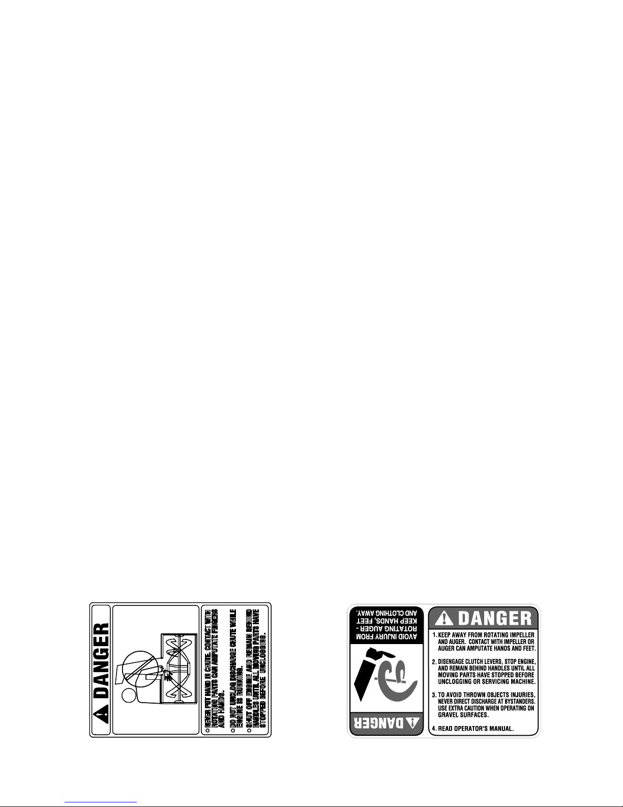
Your Responsibility:
Restrict the use of this power machine to persons who
read, understand and follow the warnings and
instructions in this manual and on the machine. The
safety labels are given below for your reference.
4
Page 5
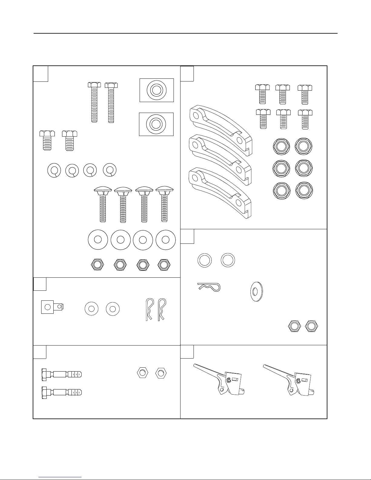
SECTION 2: CONTENTS OF HARDWARE PACK
Lay out the hardware according to the illustration for identification purposes. Part numbers are shown in
parentheses. (Hardware pack may contain extra items which are not used on your unit.)
ATTACHING THE HANDLES
A
Hex Bolts
5/16-18 x 1-3/4”
(710-3180)
Hex Bolts
(710-3008)
Carriage Bolts
5/16-18 x 1-1/2”
(710-0262)
Cupped Washers
5/16” I.D.
(736-0242)
Hex Nuts
5/16” Thread
(712-3010)
5/16-18 x 3/4” Handle Tabs
(784-5599)
Lock Washers
5/16” I.D.
(736-0119)
ATTACHING THE CHUTE ASSEMBLY
B
Hex Bolts
(710-3015)
1/4-20 x 3/4”
Chute Flange
Keepers
(731-0851A)
ATTACHING THE CHUTE DIRECTIONAL
C
CONTROL ASSEMBLY
Flat Washers
3/8” I.D. x 5/8” O.D.
(736-0185)
Hex Lock Nuts
1/4-20 Thread
(712-3027)
ATTACHING THE SHIFT ROD
D
AND CLUTCH CABLES
Hair Pin Clip
(714-0104)
Ferrule
(711-0677)
AUGER SHEAR BOLTS (SPARES)
E
NOTE: The augers are s ecured to the sp iral sh aft with two sh ear b olts and hex loc k nuts. If you h it a ha rd fo reign
object or an ice jam, the snow thrower is des igned so that the bolts may shear. Two replacement sh ear bolts and
nuts are provided for your convenience. Store in a safe place until needed.
Flat Washers
3/8” I.D. x 5/8” O.D.
(736-0275)
Shear Bolts
(710-0890A)
Hair Pin Clip
(714-0104)
Hex Lock Nuts
5/16” Thread
(712-0429)
Eyebolt Not Shown
(747-0697)
ATTACHING THE TRACK CONTROLS
F
Track Control Triggers
(746-0950)
Hex Nut
5/16” Thread
(712-3010)
Cupped Washers
5/16” I.D.
(736-0242)
5
Page 6
SECTION 3: ASSEMBLING YOUR SNOW THROWER
NOTE: Reference to right or left side of the snow
thrower can be deter mined from behind the unit in the
operating position.
Unpacking
• Remove staples or break glue on the top flaps of
the carton. Remove any loose parts included with
unit (i.e., operator’s manual, etc.).
• Cut corners and lay end of carton down flat.
Remove packing material.
• Roll unit out of carton. Check carton thoroughly for
loose parts.
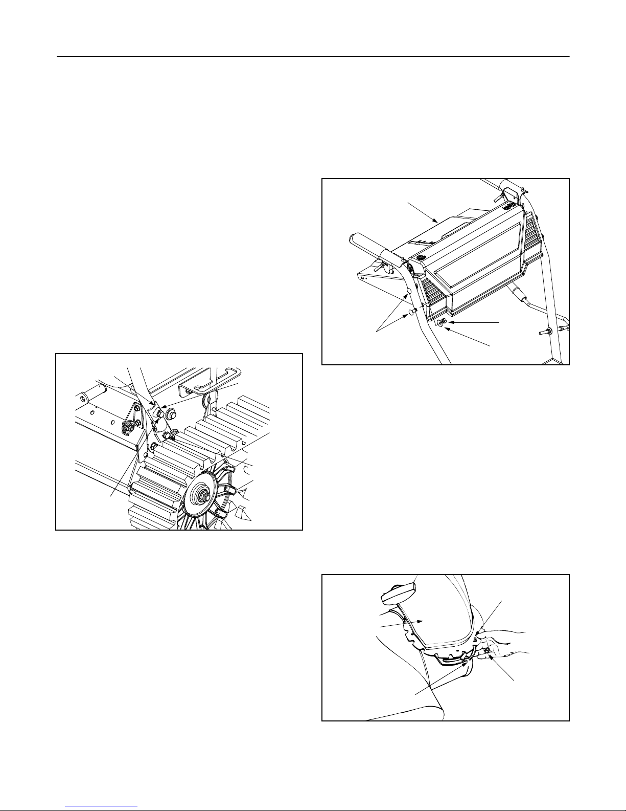
Attaching Handle Assembly
(Use Hardware A)
• Place right handle in position so the flat side of the
handle is against the snow thrower. Secure bottom
hole in handle to snow thrower using hex bolt 3/4”
long and lock washer. Do not tighten at this time.
See Figure 1.
Handle Tab
Lock Was her
washers (cupped side against handle panel) and
hex nuts.
• Secure the left side of the handle panel in the same
manner.
• Tighten the four hex bolts used to attach the bottom
of the han dles t o th e snow throw er fr ame.
Handle
Panel
Hex Nut
Carriage
Bolts
Figure 2
Cupped
Washer
Hex Bolt
3/4”
Hex Bolt
1-3/4”
Figure 1
• Place handle tab over the upper hole in handle, so
the curve in the handle tab matches the curve in the
handle. Secure to the snow thrower using 1-3/4”
hex bolt and lock washer. Do not tighten at this
time.
• Attach the left handle in the same manner and do
not tighten at this time.
• Place the handle panel in position between the
handles. To hold the handle panel in place, depress
both controls against the handles. While continuing
to hold the right control, release the left control (the
auger control lock will keep left control engaged).
See Figure 2.
• Fasten right side of the handle panel by inserting
two carriage bolts through handle and handle panel
(bolts must go through both the plastic and metal
parts of the handle panel). Secure with cupped
Attaching Chute Assembly
(Use Hardware B)
• Place chute assembly over chute opening, with the
opening in the chute assembly facing the front of
the unit.
• Place chute flange keepers beneath lip of chute
assembly with the flat side down. Insert hex bolt up
through chute flange keeper and chute assembly.
Secure with hex lock nut. See Figure 3.
• After assembling all three chute flange keepers,
tighten all nuts and bolts. Do not overtighten
hardware as it will restrict movement of the
discharge chute.
Hex Bolts
Chute
Assembly
Hex Lock
Chute Flange
Keepers
Figure 3
Nut
6
Page 7
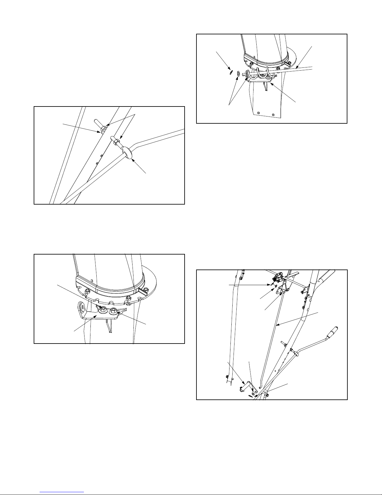
Attaching Chute Directional Contr ol
(Hardware C)
• Thread one hex nut about halfway onto eye bolt on
the chute directional control. Insert eye bolt through
the hole provided in the left handle. See Figure 4.
• Secure with cupped washer (cupped side against
the handle) and other hex nut. Do not tighten until
after attaching the other end of the chute directional
control.
Hex Nut
Cupped
Washer
Hairpin
Clip
Flat
Washers
Chute
Directional
Control
Lower Chute
Bracket
Figure 6
Eye Bolt
Figure 4
• To align the spiral on the chute directional control, it
may be necessary to loosen the carriage bolts and
hex lock nu ts whic h secu re the lower chute brac ket
to the extension on the left side of the chute
assembly. See Figure 5.
Carriage
Bolts
IMPORT ANT :
Attach the shift rod and clutch cables as
follows. Check adjustments as instructed and make any
necessary adjustments before operating your snow
thrower. Failure to follow the instructions may cause
damage to the snow thrower.
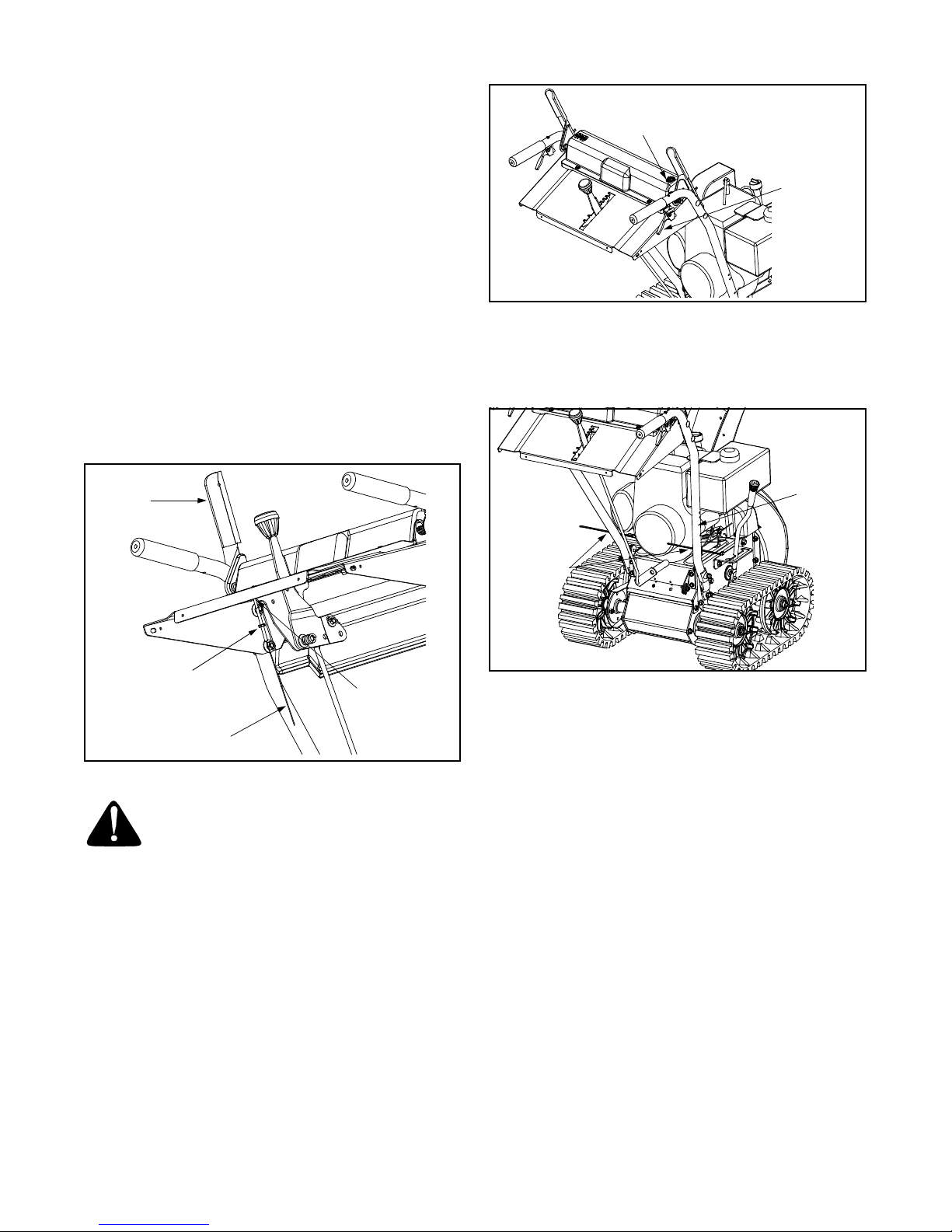
Attaching Shift Rod
(Use Hardware D)
• Place the shift lever (on the handle panel) in the
sixth (6) speed position (all the way forward).
• Place the bent end of the shift rod into the hole in
the shift arm assembly. Secure with flat washer and
hairpin clip. See Figure 7.
• Start threading the ferrule onto the other end of the
shift rod. Push down on the shift rod (and shift arm
assembly) as far as it will go.
Hairpin
Clip
Flat
Washer
Ferrule
Shift Rod
Lower Chute
Bracket
Figure 5
• Place one flat washer on the end of the chute
directional control, then insert the end of the control
into the hole in the plastic bushing in the lower
chute bracket. Place another flat washer on the end
of the chute directional control, and insert hairpin
clip into hole in the end of control. See Figure 6.
• Adjust the chute bracket so that the spiral on the
chute directional control fully engages the teeth on
the chute assembly. Tighten the nuts on the lower
chute bracket securely. Tighten the hex nut on the
eye bolt on the chute directional control.
Hex Lock
Nuts
Shift Arm
Assembly
Flat
Washer
Hairpin
Clip
Figure 7
• Thread the ferrule onto the shift rod until the ferrule
lines up with the upper hole in the shift lever
(beneath the handle panel). Insert the ferrule into
the upper hole in the shift lever from the left side
when adjustment is correct. Secure with flat washer
and hairpin clip. See Figure 7.
7
Page 8
• Make certain to check for correct adjustment of the
shift rod as instructed in the Final Adjustment
section before operating the snow thrower.
Screw
Attaching Control Cables
The Z-end of the control cables are hooked into the
control grips on each handle. Attach cables as follows:
• Thread the hex jam nuts all the way up the
threaded portion of the Z-ends of the control
cables.
• Make certain each cable is in groove of cable roller
guides. Place the control grip in the raised position.
• Thread the cable onto the threaded portion of the Zend until there is no slack in the cable, making sure
cable is straight. Do not overtighten cable.
See Figure 8.
• When correct adjustment is reached, tighten the
hex jam nut against the bottom portion of the cable
to lock it in position.
Auger
Control
Right Track
Control
Figure 9
• Secure the track control cables to the inside of the
lower handle using the cable ties provided. Pull the
cable ties tight and trim the excess ends of the
cable ties. See Figure 10.
Handle
Cable Ties
Hex Jam
Nut
Make Sure
Cable is Straight
Figure 8
WARNING: If cable is tighten so there is
tension on the cable with the control grip
released, the safety fea tures of the snow
thrower may be overridden.
Z-End
Attaching Track Controls
(Use Hardware F)
• Remove the screw from the top of the right hand
track control. Be careful not to lose the flat weld nut
that is inside the control.
• Place the right track control in position underneath
the right handle. Secure with screw previously
removed. See Fi gure 9.
• Secure the left track control in the same manner.
• Attach track control cable to track control handle by
inserting cable ball into slot on track control handle.
Pull cable down and up until it snaps into front of
track control handle. Repeat on other side.
Figure 10
FINAL ADJUSTMENTS
Auger Control Adjustment
Check the adjustment of the auger control as follows:
• Push forward on the auger control until the small
rubber bumper contacts the upper handle. There
should be slack in the cable. See Figure 8.
• Release the auger control. The cable should be
straight. Make certain you can depress the auger
control against the left handle completely.
If adjustment is necessary, proceed as follows:
• Loosen the jam nut and thread the cable in (for less
slack) or out (for more slack) as necessary. See
Figure 8.
• Recheck th e adjustm ent bef ore reti ghtenin g the
jam nut against the cable.
Skid Shoe Adjustment
The space between the shave plate and the ground can
be adjusted by repositioning the skid shoes found on
either side of the snow throwers auger housing. For
close snow removal, place skid shoes in the low
position. Use middle or high position when area to be
cleared is uneven. See Figure 11.
8
Page 9
IMPORT ANT :
thrower be operated on a gravel surface, as loose
stones can be easily picked up and thrown by the
machine. If you must operate on a gravel surface,
ALWAYS adjust the skid shoes into the HIGH position
to allow the shave plate maximum clearance.
Adjust skid shoes as follows:
• Loosen, but do NOT remove, the three hex nuts
which fasten the skid shoe to the auger housing.
• Raise or lower the skid shoe to desired position.
NOTE: Make certai n t he en t ir e ba s e of bo th skid s hoe s
are against the ground to avoid uneven wear on the
skid shoes. When one side does wear out, the skid
shoes are reversible.
Skid
Shoes
• Retighten the hex nuts loosened earlier.
• Repeat this adjustment on the skid shoe found on
the opposite side of the snow thrower.
It is NOT recommended that this snow
Hex Nuts
Figure 11
Traction Control and Shift Lever Adjustment
To check the adjustment of the traction control and shift
lever, proceed as follows:
• Move the shift lever into sixth (6) position.
a. With the traction control (refer to Figure 12)
released, squeeze in triggers and gently
push the snow th rower fo rward, th en pull it
back. Disregarding the overall weight of the
snow thrower, the machine should otherwise
move freely.
b. Engage the traction control and attempt to
move them m achi ne bot h for ward and
rearward. You should experience resistance
as the tracks should not be turning.
• Move the shift lever in to the f ast revers e (R2)
position and repeat the previous steps (a & b).
If you experienced resistance either when repositioning
the shift lever from 6 to R2 or when attempting to move
the machine forward or rearward with the traction
control rel eased, yo ur snow t hrower’s traction control is
in need of adjustment and you should NOT operate the
machine before completing the adjustment as follows:
• Loosen the jam nut on the traction control cable
and UNTHREAD the cable one full turn.
• Recheck the adjustment.
• Retighten the jam nut to secure the cable when
correct adjustment is reached.
If the machine can be moved freely both forward and
rearward when the traction control fully depressed,
proceed as follows:
• Loosen the jam nut on the traction drive cable and
THREAD the cable in one full turn.
• Recheck the adjustment and repeat adjustment as
necessary.
• Retighten the jam nut to secure the cable when
correct adjustment is reached.
NOTE: If you are uncert ain that you have rea ched the
correct adjustment, refer to Traction Control Adjustment in Adjustment Section.
SECTION 4: KNOW YOUR SNOW THROWER
WARNING: Read, understand, and follow
all instructions and warnings on the
machine and in this manual before
operating.
Traction Control / Auger Control Lock
The traction control is located on the right handle.
Squeeze the traction control to engage the track drive.
Release to stop. See Figure 12.
This same lever also locks the auger control so you can
turn the chute directional control without interrupting the
snow throwing process. If the auger control is engaged
along with the traction control, the operator can release
the auger control (on the left handle) and the augers will
remain engaged. Release the traction control to stop
both the augers and track drive (auger control must
also be released).
Auger Drive Control
The auger drive control is located on the left handle.
Squeeze the control grip to engage the augers.
Release to stop the snow throwing action. (Traction
control must also be released.) See Figure 12.
9
Page 10
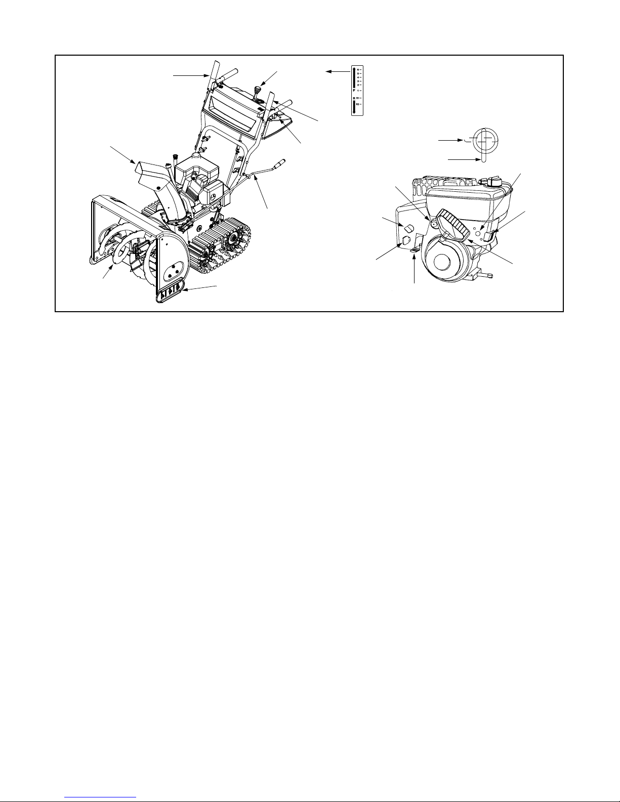
Traction Control /
Auger Control Lock
Discharge
Chute
Shift Lever
Track Steering
Control
Auger Drive
Control
Primer
Closed
Open
Electric
Starter
Button
Chute Directional
Control
Auger
Skid Shoe
Figure 12
Shift Lever
The shift lever is located in the center of the handle
panel and is used to determine both ground speed and
direction of travel. It can be moved into any of eight
positions. See Figure 12.
Forward
Your snow thrower has six forward (F) speeds. Position
number one (1) is the slowest. Position number six (6)
is the fastest.
Reverse
Your snow thrower has two reverse (R) s peeds. R1 is
the slower, while R2 is the faster of the two.
IMPORT ANT :
changing speeds.
Always release tractional control before
Chute Directional Contr ol
The chute directional control is located on left side of
the snow thrower. See Figure 12.
To change the direction in which snow is thrown, turn
chute directional control as follows:
• Crank clockwise to discharge to the left.
• Crank counterclockwise to discharge to the right.
Choke
Safety
Ignition Key
Throttle
Control
NOTE: It is easier to maneuver a non-running snow
thrower with both track steering controls held in
simultaneously.
Switch
Box
Recoil
Starter
Handle
Headlight ( If Eq uipped)
The headlight is on whenever the engine is running.
Skid Shoe
The position of the skid shoe is determined by the
condition of the ground from where snow has to be
removed. See Figure 12.
Throttle Control
The throttle control is located on the engine. It regulates
the speed of the engine and will shut off the engine
when pushed down completely. See Figure 12.
Safety Ignition Key
The safety ignition key must be fully inserted in the
switch before the unit will start. Remove the ignition key
when the snow thrower is not in use. See Figure 12.
IMPORT ANT :
Do NOT attempt to turn the key.
Track Steering Controls
The left and right track steering controls are located on
the underside of the handles and are used to assist in
steering the snow thrower. Squeeze the right track
control when turning right and squeeze the left control
when turning left. Operate your snow thrower in open
areas until you become familiar with these controls.
See Figure 12.
Fuel Shut-off Valve
The fuel shut-off valve, located under the fuel tank,
controls fuel flow from the tank. Always make certain it
is in the Open (vertical) position before attempting to
start the engine. See Figure 12.
10
Page 11

Track Lock Lever
The track lock lever is located on the right side of the
snow thrower and is used to select the position of the
auger housing and the method of track operation. Move
the lever to the right, then forward or backward to one of
the three positions. See Figure 13.
Transport: Raises the front end of the snow thrower for
easy transport. Using proper caution, this position may
also be used on many gravel driveways to clear snow
while leaving gravel undisturbed.
Packed
Snow
Normal Snow: Allows the tracks to be suspended
independently for continuous ground contact.
Packed Snow: Locks the front end of the snow thrower
down to the ground for hard-packed or icy snow
conditions.
SECTION 5: OPERATING YOUR SNOW THROWER
Normal
Snow
Track Lock
Lever
Transport
Figure 13
Before Starting
WARNING: Read, understand, and follow
all instructions and warnings on the
machine and in this manual before
operating.
Gas And Oil Fill-up
Service the engine with gasoline and oil as
instructed in the separate engine manual packed with
your snow thrower. Read instructions carefully.
WARNING: Use extreme care when
handling gasoline. Gasoline is extremely
flammable and the vapors are explosive.
Never fuel machine indoors or while the
engine is hot or running. Extinguish
cigarettes, cigars, pip es an o th er s our ces
of ignition.
• A plastic cup is provided inside the fuel fill opening
on the fuel tank. Remove and discard this cup
before filling up the tank. Use the separate fuel tank
cap to close after fill-up.
To Start Engine
NOTE: If unit shows any sign of motion (drive or
augers) with the clutch g rips disengaged, shut engine
off immediately. Readjust as instructed in the Final
Adjustments in the Assembly Section.
• Attach spark plug wire to spark plug. Make certain
the metal loop on end of the spark plug wire (inside
the boot) is fastened securely over the metal tip on
the spark plug.
• Make certain the fuel cutoff valve is in the OPEN
(vertical position). See Figure 12.
• Make certain the auger and drive clutch levers are
in the disengaged (released) position.
• Move throttle control up to FAST position. Insert
ignition key into slot. See Figure 12. Be certain it
snaps into place. Do not turn key.
NOTE: Engine will not start unless ignition key is
inserted into ignition slot in carburetor cover.
Electric Starter
• Determine that your house wiring is a three-wire
grounded system. Ask a licensed electrician if you
are not certain.
• If your house wiring system is not a three-wire
grounded system, do not use this electric starter
under any condi tions.
WARNING: The electric starter is
equipped with a grounded three-wire
power cord and plug and is designed to
operate on 120 volt AC household
current. It must be used with a properly
grounded three-prong receptacle at all
times to avoid the possibility of electric
shock. Follow all instructions carefully
prior to operating the electric starter.
• If your home electrical system is grounded, but a
three-hole receptacle is not available, one should
be installed by a licensed electrician before using
the electr ic start er.
• If you have a grounded three-prong receptacle,
proceed as follows:
• Rotate choke knob to OFF position and do not
prime engine.
11
Page 12

• Connect power cord to switch box on engine. Plug
the other end of power cord into a three-hole,
grounded 120 volt AC receptacle.
• Push starter button on top of the engine to crank
engine. As you crank the engine, move choke knob
to FULL choke position.
• When engine starts, release starter button, and
move choke gradually to OFF. If engine falters,
move choke immediately to FULL and then
gradually to OFF.
• When disconnecting the power cord, always unplug
from the three-prong receptacle first and then from
the snow thrower.
Recoil Starter
• Rotate choke knob to FULL choke position (cold
engine start). If engine is warm, place choke in OFF
position instead of FULL.
• Push primer button two or three times. If engine is
warm, pus h prim er but ton on ce on ly.
NOTE: Always cover vent hole in primer button when
pushing. Additional prim ing may be necessary for firs t
start if temperature is below 15°F.
• Grasp starter handle and pull rope out slowly, until
it pulls slightly harder. Let rope rewind slowly.
• Pull starter handle rapidly. Do not allow handle to
snap back. Allow it to rewind slowly while keeping a
firm hold on the starter handle.
• Repeat the previous steps until engine starts.
Wipe all snow and moisture from the carburetor cover
in the area of the control levers. Also, move control
levers back and forth several times.
To Engage T rack Driv e
• With the engine running near top speed, move the
shift lever into one of the six FORWARD positions
or two REVERSE positions. Select a speed
appropriate for the snow conditions that exist.
NOTE: Use slower speeds in higher snow and until you
are familiar with the operation of the snow thrower.
• Squeeze the traction control against the right
handle and the snow thrower will move. Release it
and the drive motion will stop.
IMPORT ANT :
releasing the traction control. Doing so will cause
premature wear to the drive system’s friction wheel.
NEVER move the shift lever without first
To Engage Augers
To engage the augers and start the snow throwing
action, proceed as follows:
• Squeeze the auger control against the left handle.
To disengage power to the augers:
• Release both the auger control and the traction
control, if engaged.
The auger control can be locked so you can turn the
electric chute directional control without interrupting the
snow thro wing pr oces s.
To Stop Engine
• Run engine for a few minutes before stopping to
help dry off any moisture on the engine.
• To help prevent possible freeze-up of starter,
proceed as follows.
Electric Starter:
• Connect power cord to switch box on engine, then
to 120 volt AC receptacle. With the engine running,
push starter button and spin the starter for several
seconds. The unusual sound made by spinning the
starter will not harm engine or starter. Disconnect
the power cord from receptacle first, and then from
switch box.
Recoil Starter
• With engine running, pull starter rope with a rapid,
continuous full arm stroke three or four times.
Pulling the starter rope will produce a loud clattering
sound, which is not harmful to the engine or starter.
• Move throttle control to “stop” or “off” position.
• Remove ignition key. Do not turn key. Disconnect
the spark plug wire from the spark plug to prevent
accidental starting while equipment is unattended.
NOTE: Keep it in a safe place. Engine will not start
without ignition key.
Operating Tips
NOTE: Allow the engine t o w arm up for a few minut es.
The engine will not develop full power until it reach es
operating temperature.
WARNING: The temperature of the
muffler and the surrounding areas may
exceed 150
• For the most efficient snow removal, remove snow
immediately after it falls.
• Discharge the snow downwind whenever possible.
• Slightly overlap each previous path.
• Set the skid shoes 1/4" below the shave plate for
normal usage. The skid shoes may be adjusted
upward (to lo wer the sh ave plat e) for har d-packe d
snow. Adjust downward (to raise the shave plate)
when using on gravel or crushed rock.
• Be certain to follow the precautions found in the To
Stop Engi ne sec tion to pr even t possi ble freez e-up.
• Clean the snow thrower thoroughly after each use.
°
F. Avoid these areas.
12
Page 13

SECTION 6: MAKING ADJUSTMENT
WARNING: NEVER attempt to make any
adjustments while the engine is running,
except where specif ied in the operator’s
manual.
Auger Control Adjustment
Refer to the information found under Final Adjustments in the Assembly Section to adjust the auger
control.
Traction Control Adjustment
Refer to the information found under Final Adjustment
in the Assembly Section to adjust the traction control. If
you are uncertain that you have reached the correct
adjustment, proceed as follows:
WARNING: Drain the gasoline out of the
snow thrower’s tank, or place a piece of
plastic film under the gas cap to avoid
spillage BEFORE making the adjustment.
• Tip the snow thrower forward, allowing it to rest on
the auger housing.
• Remove the frame cover underneath the snow
thrower by removing the six self-tapping screws.
• With the traction control released, there must be
clearance between the friction wheel and the drive
plate in all positions of the shift lever.
• With the traction control engaged, the friction wheel
must contact the drive plate. See Figure 14.
Gear Shaft
Drive
Cable
Chute Directional Contr ol And Support
Bracket Adjustment
If the spiral at the base of the chute directional control is
not fully engaging with the notches in the lower chute
assembly, the support bracket can be adjusted inward
or outwar d as follow s:
• Loosen, but do NOT remove the two hex nuts
which secure the chute directional control support
bracket to the snow thrower housing.
See Figure 15.
Spiral
Hex Nuts
Figure 15
• Adjust the support bracket inward or outward so
that the spiral is fully engaged in the notches on the
chute before retightening the hex nuts.
Support
Bracket
Shift Rod Adjustment
To adjust the shift rod, proceed as follows:
• Remove the hairpin clip and slide the shift rod
connector up, to separate the upper shift rod from
the lower shift rod. See Figure 16.
Friction Wheel
Rubber
Figure 14
If adjustment is necessary:
• Loosen the jam nut on the traction drive cable.
Adjust the cable as necessary. Refer to Figure 8.
• Retighten the jam nut to secure the cable when
correct adjustment is reached.
• Reassemble the frame cover.
Pivot Rod
Drive
Plate
13
Hairpin
Clip
Shift Arm
Assembly
Flat
Washer
Ferrule
Flat
Washer
Shift Rod
Hairpin
Clip
Figure 16
Page 14

• Place the shift lever into the sixth (6) position.
• Rotate the shift arm clockwise (from the operator’s
position) as far as it will go.
• Thread the upper shift rod downward until the
elbow on its lower end aligns with the hole found in
the lower shift rod.
• Reconnect the upper shift rod to the lower shift rod
by reinsertin g the hairpi n clip remo ved earlie r and
sliding the shift rod connector back down into place.
IMPORT ANT :
adjustment of the shift rod as instructed under Final
Adjustments in the Assembly Section, before operating
the snow thrower.
Make certain to check for correct
Skid Shoe Adjustment
The space between the shave plate and the ground can
be adjusted by raising or lowering the skid shoes. Refer
to Skid Shoe Adjustment in the Assembly Section.
Chute Assembly
The angle of the discharge chute controls the distance
the snow is thrown. The distance snow is thrown can be
adjusted by tilting the discharge chute up for greater
distance or tilting down for less distance. Loosen the
hand knob on the side of the discharge chute to adjust.
Tilt the chute to desired position and tighten hand knob.
SECTION 7: MAINTAINING YOUR SNOW THROWER
WARNING: Before lubricating, repairing,
or inspecting, disengage all clutch levers
and stop engine. Wait until all moving
parts have come to a complete stop.
Disconnect spark plug wire and ground it
against the engine to prevent unintended
starting.
Lubrication
Gear Shaft
Lubricate the gear shaft with 6-n-1 grease at least once
a season or after every 25 hours of operation (available
at automotive stores, or order part number 737-0170).
Refer to Figure 14.
IMPORT ANT :
friction wheel and aluminum drive plate.
Drive and Shifting Mechanism
Lubricate at least once a season or after every 25 hours
of operation. Remove the rear cover, lubricate any
chains, sprockets, gears, bearings, shafts, and shifting
mechanism at least once a season. Use engine oil or a
spray lubricant. Avoid getting oil on the friction
wheel rubber and aluminum drive plate. Refer to
Figure 14.
There is a grease fitting on the top of the axle shaft
which drives the rear track drive wheels on both sides
of the unit. Grease these fittings every 25 hours or once
a season.
Traction Control / Auger Cont rol Lock
The cams on the ends of the control rods which
interlock the traction drive and auger drive controls
must be lubricated at least once a season or every 25
hours of operation. The cams can be accessed beneath
the handle panel. Use a multi-purpose automotive
grease.
Chute Directional Control
The spiral on the end of the chute directional control
Keep all grease and oil off of the rubber
and the base of the discharge chute itself should be
lubed with multi-purpose automotive grease once a
season. See Figure 17.
Lube Spiral &
Chute Base
Figure 17
Auger Shaft
At least once a season, remove the shear bolts on the
auger shaft. Spray lubricant inside the shaft. Also
lubricate the plastic auger bearings at least once a
season on the end of the auger shaft with a standard
grease gun. See Figure 18.
Vent Plug
Plastic
Bearing
Shear Bolts
Figure 18
Plastic
Bearing
14
Page 15

Gear Case
The gear case is lubricated with grease at the factory
and does not require checking. If disassembled for any
reason, lubricate with 2 ounces of Shell Alvania grease
EPR00, part number 737-0168. Before reassembling,
remove old sealant and apply new sealant.
the seals could result. Be sure the vent plug is free of
grease in order to relieve pressure.
Engine
Refer to the separate engine m anual p acked with yo ur
unit for all engine lubrication instructions.
IMPORT ANT :
Do not overfill the gear case. Damage to
SECTION 8: SERVICING YOUR SNOW THROWER
WARNING: Before servicing, repairing, or
inspecting, disengage all clutch levers and
stop engine. Wait until all moving parts
have come to a complete stop. Disconnect
spark plug wire and ground it against the
engine to prevent unintended starting.
Engine
Refer to the separate engine manual packed with your
unit for all engine maintenance procedures.
Augers
• The augers are secured to the spiral shaft with two
shear bolts and hex lock nuts. If you hit a hard
foreign object or ice jam, the snow thrower is
designed so that the bolts may shear.
Refer to Figure 18.
• If the augers will not turn, check to see if the bolts
have sheared. Replacement shear bolts and hex
lock nuts have been provided with the snow
thrower. When replacing bolts, spray an oil
lubricant into shaft before inserting new bolts.
Belt Removal And Replacement
Auger Belts
• Remove the plast ic bel t cover by re movin g the t wo
self-tapping screws. See Figure 19.
• Drain the gasoline from the snow thrower.
• Tip the snow thrower up and forward so that it rests
on its auger housing.
Belt Cover
Self-Tapping
Screw
Figure 19
IMPORT ANT :
standard hex bolts. Any damage to the auger gearbox
or other components as a result of doing so will NOT be
covered by your snow thrower’s warranty.
NEVER replace the auger shear bolts with
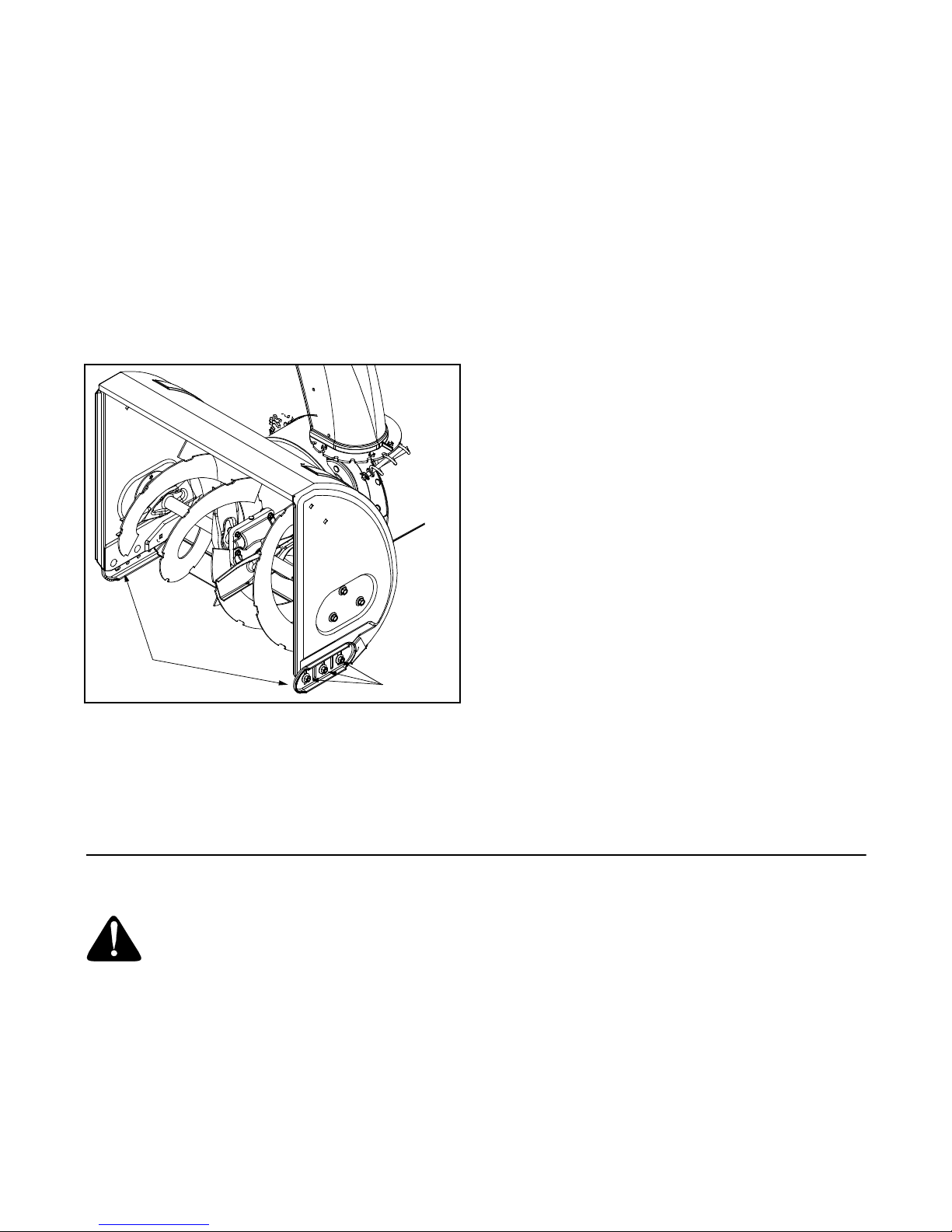
Shave Plate and Skid Shoes
The shave plate and skid shoes on the bottom of the
snow thro wer ar e subj ect to we ar. T hey sh ould be
checked periodically and replaced when necessary. To
remove the skid shoes, proceed as follows:
• Remove the six carriage bolts, bell washers, and
hex nuts which attach them to the snow thrower.
• Reassemble new skid shoes with the six carriage
bolts, bell washers (cupped side goes against skid
shoes) and hex nuts. Make certain the skid shoes
are adjusted to be level.
To remove shave plate, remove the carriage bolts, bell
washers, and hex nuts which attach it to the snow
thrower housing. Reassemble new shave plate, making
sure heads of the carriage bolts are to the inside of the
housing. Tighten securely.
• Remove the six self-tapping screws from the frame
cover underneath the snow thrower.
• Roll the front and rear auger belts off the engine
pulley. See Figure 20.
Auger
Pulley
Idler
Pulley
Figure 20
15
Drive
Belt
Idler
Pulley
Auger
Belts
Frame
Drive
Pulley
Page 16

• Unhook the idler spring from the hex bolt on the
auger housing. See Figure 21.
• Back out the stop bolt until the support bracket
rests on the auger pulley.
NOTE: Loosening the six nuts that connect the frame to
the auger housing may aid in belt removal.
Support
Bracket
Auger
Pulley
Rear
Auger
Belt
Frame
Support
Bracket
Spring
NOTE: The suppo rt bracket must rest on the stop bolt
after the new belt has been assembled.
Servicing Friction Wheel Rubber
The rubber on the friction wheel is subject to wear and
should be checked after 25 hours of operation, and
periodically thereafter. Replace the friction wheel
rubber if any signs of wear or cracking are found.
• Drain the gasoline from the snow thrower.
• Tip the snow thrower up and forward, so that it rests
on the housing.
• Remove six self-tapping screws from the frame
cover underneath the snow thrower.
• Remove the click pins which secure the wheels,
and remove the wheels from the axle.
• Using a 7/8" wrench to hold the shaft, loosen, but
do not completely remove, the hex bolt and bell
washer on the left end of gear shaft. See Figure 22.
Front
Auger Belt
Stop Bolt
Support Bracket
Idler
Spring
Friction
Wheel
Auger
Housing
Drive Plate
Auger Pulley
Figure 21
• Lift the auger belt from the auger pulley and slip belt
between the support bracket and the auger pulley.
Repeat this step for the front auger belt.
See Figure 21.
• Replace the auger drive belts by following
instructions in reverse order.
Drive Belt
• Follow the first four steps of the instructions for
servicing the auger belts.
• Pull the idler pulley up and lift the belt off the engine
pulley and friction wheel disc. See Figure 20.
• Back out the stop bolt until the support bracket
rests on the auger pulley.
• Slip the belt between the friction wheel and drive
disc. Remove and replace the belt. Reassemble
following the instructions in reverse order.
Hex Bolt &
Washer
Track
Figure 22
• Lightly tap the hex nut to dislodge the ball bearing
from the right side of frame before removing the hex
nut and bell washer from left end of shaft.
• Move the gear shaft to the right and slide the friction
wheel assembly from the shaft. See Figure 23.
• Remove the six screws from the friction wheel
assembly (three from each side). Remove the
friction wheel rubber from between the friction
wheel plates. See Figure 23.
• Reassemble new friction wheel rubber to the
friction wheel plates and hub, tightening the six
screws in rotation and with equal force.
• Position the friction wheel assembly up onto the pin
of the shift rod assembly, and slide the shaft
through th e asse mbly . Reas sembl e in re verse
order.
16
Page 17

Spacer
Sprocket
Support
Bracket
Screws
Friction Wheel Plates
Figure 23
Off-season Storage
WARNING: Never store the machine or
fuel container indoors where there is an
open flame, spark, or pilot light such as on
water heater, furnace, clothes dryer, or
other gas appliance.
Shift Rod
Assembly
Pin
Friction Wheel
Assembly
Shaft
Friction Wheel Rubber
Hub
Screws
WARNING: Drain fuel into an approved
container outdoors, away from an open
flame. Allow engine to cool. Extinguish
cigarettes, cigars, pipes, and other
sources of ignition prior to draining fuel.
Fuel left in engine for extended periods
deteriorates and will cause starting
problems.
If unit is to be stored over 30 days, prepare for storage
as follows:
• Remove gasoline from carburetor and fuel tank to
prevent gum deposits from forming on these parts
and causing possible malfunction of engine.
• Run engine until fuel tank is empty and engine
stops due to lack of fuel.
• Drain carburetor by pressing upward on bowl drain,
located below the carburetor cover.
NOTE: Fuel stabilizer is an acceptable alternative in
minimizing the formation of fuel gum deposits during
storage. Do not drain carburetor if using fuel stabilizer.
• Wipe equipment with an oiled rag to prevent rust.
• Remove spark plug and pour one ounce of engine
oil through spark plug hole into cylinder. Cover
spark plug hole with rag. Crank engine several
times to distribute oil. Replace spark plug.
• Follow the lubrication recommendations found in
the Maintenance Section.
• Always store the snow thrower in a clean, dry area.
When storing any type of power equipment in an
unventilated or metal storage shed, care should be
taken to rust proof the equipment. Using a light oil or
silicone, coat the equipment, especially any chains,
springs, bearings and cables.
17
Page 18

SECTION 9: TROUBLESHOOTING
Problem Cause Remedy
Engine fails to start 1. Fuel tank empty, or stale fuel.
2. Blocked fuel line.
3. Choke not in the ON position
4. Faulty spark plug.
5. Safety key not in ignition switch on engine.
6. Spark plug wire disconnected.
7. Primer button not being used properly.
8. Fuel shut-off valve closed.
Engine runs erratic 1. Unit running on CHOKE.
2. Blocked fuel line or stale fuel.
3. Water or dirt in the fuel system.
Loss of power 1. Spark plug wire loose.
2. Gas cap vent hole plugged.
Excessive vibration 1. Loose parts or damaged auger. 1. Stop the engine immediately and
Unit fails
to propel itself
Unit fails
to discharge snow
1. Traction control cable in need of
adjustment.
2. Drive belt loose or damaged.
1. Discharge chute clogged.
2. Shear bolt sheared.
3. Foreign object lodged in auger.
4. Auger control cable in need of adjustment.
5. Auger belt loose or damaged.
6. Shear bolt(s) sheared.
1. Fill tank with clean, fresh gasoline. Fuel
becomes stale after thirty days.
2. Clean the fuel line.
3. Move switch to the ON position
4. Clean, adjust gap or replace.
5. Insert the key fully into the switch.
6. Connect spark plug wire.
7. Refer to the engine manual.
8. Open fuel shut-off valve.
1. Move the choke lever to OFF position.
2. Clean the fuel line; fill the tank with
clean, fresh gasoline.
3. Drain the fuel tank and carburetor.
Refill with fresh fuel.
1. Connect and tighten spark plug wire.
2. Remove ice and snow from gas cap. Be
certain vent hole is clear.
disconnect the spark plug wire. Tighten
all bolts and nuts. If vibration continues,
have the unit serviced by an authorized
service dealer.
1. Adjust traction control cable. Refer to
Making Adjustment Section.
2. Replace drive belt. Refer to the Service
Section.
1. Stop engine and disconnect spark plug
wire. Clean discharge chute and inside
of auger housing.
2. Replace shear bolt.
3. Stop engine immediately and
disconnect spark plug wire. Remove
object from auger.
4. Adjust auger control cable. Refer to the
Making Adjustments Section.
5. Refer to Service Section.
6. Replace shear bolt(s ).
18
Page 19

Model E740F
4
11
9
16
13
1
17
14
8
15
10
5
6
3
12
7
2
3
Ref.
No.
1. 618-0123 RH Housing
2. 618-0124 LH Housing
3. 710-0642 Self Tapping Screw, 1/4-20 x .75
4. 711-0909A Spiral Axle 26”
5. 714-0161 Hi-Pro Key, 3/16 x 5/8
6. 715-0143 Spring Spiral Pin, .25 x 1.25
7. 717-0528 Worm Gear, 20-tooth
8. 717-0526 Worm Shaft
9. 718-0186 Thrust Collar
10. 721-0325 Grease Plug
11. 721-0327 Grease Seal
12. 736-0351 Flat Washer, .76 x 1.5 x .030
13. 736-0369 Flat Washer, .508 x 1.0 x .020
14. 736-0445 Flat Washer, .76 x 1.5 x .060
15. 741-0662 Flange Bearing, .75 x 1.0 x .59
16. 741-0663 Flange Bearing, .503 ID x .75 OD
17. 618-0121A Gear Assembly Comple te , 26”
Part No. Part Description
19
Page 20

Model E740F
1
53
51
54
52
57
33
20
17
22
32
45
19
21
18
23
24
44
16
25
36
15
26
27
2
9
3
10
14
20
8
13
28
20
35
3
4
6
3
7
5
2
3
12
11
1
17
18
19
21
29
35
34
41
1
30
20
31
37
38
54
55
59
60
56
58
50
20
26
47
26
27
40
42
43
46
47
48
49
Page 21

Model E740F
Ref.
No.
1. 714-0507 Cotter Pin
2. 747-0877 Rod
3. 710-0599 Hex Washer Screw 1/4-20 x .5
4. 784-5680 Handle Support Brac ket — RH
5. 784-5679 Handle Support Brac ket — LH
6. 748-0362 Cam Lock Han dle
7. 748-0363 Handle Lock Paw l
8. 732-0145 Compression Spring
9. 711-0653 Clevis Pin
10. 720-0232 Knob
11. 684-0037A Handle Assy — LH
12. 784-5681 Handle Support Bracket — LH
13. 784-5619A Shift Handle
14. 784-5682 Handle Support Bracket — RH
15. 732-0746 Torsion Spring
16. 684-0036 Handle Assy — RH
17. 735-0199A Rubber Bumper
18. 736-0509 Washer
19. 736-0119 Lock Washer 5/16
20. 712-3010 Hex Nut 5/16-18
21. 746-0778 Cable
22. 684-0103 Panel
23. 712-0116 Jam Lock Nut 3/8-24
24. 732-0193 Compression Spring
25. 736-0105 Bell Washer
26. 714-0104 Cotter Pi n
27. 736-0275 Flat Washer 5/16
28. 711-0677 Ferrule
29. 710-0459A Hex Cap Screw 3/8-24 x 1.50
30. 720-0274 Grip
31. 749-0910B Handle RH
Part
No. Description
Ref.
No.
32. 710-1003 Hew Washer Screw
33. 731-1391 Handle Pan el
34. 710-0262 Carriage Bo lt 5/16-18 x 1.50
35. 736-0242 Bell Washer .34 0 ID x .872 OD
36. 747-0798A Shift Rod
37. 726-0100 Push Cap
38. 720-0201A Chute Directional Control Knob
40. 705-5204A Chute Directional Control Assembl y
41. 712-3010 Hex Nut 5/16 - 18
42. 747-0697 Chute Di rectional Control Ey ebolt
43. 735-0234 Rubber Gr ommet
44. 684-0008A Shift Arm Assembly
45. 710-0788 Hex Wash er Screw 1/4-20 x 1 .0
46. 784-5599 Handle Tab
47. 736-0119 Lock Wa sher 5/16
48. 710-3180 Hex Cap Screw 5/16 -18 x 1.75
49. 710-3008 Hex Cap Screw 5/16 -18 x .75
50. 736-0185 Flat Was her
51. 731-0921 Upper Ch ute
52. 731-1300A Lower Chute
53. 712-0429 Hex Lock Nut 5/ 16-18
54. 736-0159 5/16 Washer
55. 710-0451 Carriage Bo lt 5/16-18 x .75
56. 710-0276 Carriage Sc rew 5/16-18 x 1.0
57. 720-0284 Knob
58. 712-3027 Hex Lock Nut 1/ 4-20
59. 731-0851A Flange Keeper
60. 710-3015 Hex Cap Sc rew 1/4-20 x .75
Part
No. Description
749-0911B Handle — LH
731-1393 Handle Panel w/ Top Light
21
Page 22

Model E740F
38
18
34
2
3
4
11
10
15
14
27
28
9
13
35
12
13
9
16
22
23
10
25
26
30
43
19
7
16
1
5
6
8
18
44
21
13
23
22
39
40
37
42
18
36
41
39
29
16
17
31
40
32
33
24
22
Page 23

Model E740F
Ref.
No.
1. 712-0116 Lock Jam Nut 3/8-2 4
2. 756-0178 Flat Idler
3. 784-5632A Auger Idler Arm
4. 710-0459A Hex Cap Screw 3/8-24 x 1.50
5. 738-0281 Shoulder Screw
6. 736-0167 Flat Washer .656 ID x 1.25 OD
7. 732-0611 Extension Spring
8. 712-3068 Hex Nut 5/16-18
9. 710-0276 Carriage Bolt, 5/16-18 x 1.00
10. 736-0119 Lock Washer 5/16
11. 05931A Housing
12. 741-0309 Ball Bearing
13. 710-0451 Carriage Bolt, 5/16-18 x .75
14. 705-5226 Chute Reinforcement
15. 684-0040C 26” Hous ing Assy
16. 712-3010 Hex Nut 5/16-18
17. 712-0429 Lock Nut 5/16-18
18. 736-0242 Belleville Washer
19. 736-0231 Flat Wshr, .344ID x 1 .125 OD
21. 731-1379B Chute Adapter
22. 712-0324 Hex Lock Nut 1/4- 20
23. 736-0463 Flat Washer
Part No. Part Description
Ref.
No.
24. 784-5618 Bearing Housing
25. 710-0703 Carriage Screw 1/4-20 x .75
26. 710-0604 Hex Screw 5/16-18
27. 736-0169 Lock Washer 3/8
28. 712-0798 Hex Nut 3/8-16
29. 741-0245 Hex Flange Bearing
30. 784-5580 Skid Shoe
31. 736-0242 Bell Washer
32. 712-3010 Hex Nut 5/16-18
33. 784-5579A Shave Plate
34. 710-0451 Carriage Bolt 5/16-18 x 1 .00
35. 684-0065 Impeller Assembly
36. 715-0114 Pin
37. 618-0121A 26” Gear Assembly
38. 605-5192A 26” Spiral RH
39. 736-0188 Flat Washer
40. 741-0493A Flange Bushing
41. 605-5193A 26” Spiral LH
42. 710-0890A Shear Bolt 5/16-18 x 1.5
43. 784-5647 Chute Crank Bracke t
44. 741-0475 Bushing
Part No. Part Description
23
Page 24

Model E740F
21
20
22
19
24
18
23
17
25
19
26
27
29
30
31
34
32
2
32
35
30
20
26
10
19
25
24
23
22
2
21
12
16
18
14
3
4
5
15
8
9
7
6
11
13
1
28
36
227
19
30
39
38
32
40
32
2
37
24
Page 25

Model E740F
Ref.
No.
1. 784-5648 Frame Cover
2. 710-1652 Tap Screw 1/4-20 x .62 5
3. 748-0190 Spacer .508 ID x .75 OD
4. 732-0264 Extension Spring
5. 712-0711 Jam Nut 3/8-24
6. 736-0105 Bell Washer .401 ID x .87 OD
7. 684-0021 Friction Whl Support Bracket
8. 746-0898 Drive Cable 39.88”
9. 656-0012A Friction Disc
10. 784-5689A Front Support Guide Brac ket
11. 713-0413 10T Sprocket
12. 746-0897 Auger Cable 44.75”
13. 750-0997 Spacer .675 ID x 1” OD
14. 711-1042 Hex Track Shaft
15. 684-0042C Friction W heel Asse mbly
16. 736-0160 Flat Washer .536 ID x .93 OD
17. 714-0474 Cotter Pin
18. 741-0563 Ball Bearing
19. 736-0242 Bell Washer .34 ID x .872 OD
20. 710-0538 Hex Cap Screw 5/16-18 x .625
Part No. Part Description
Ref.
No.
21. 710-0857 Tap Screw 1/4-20 x .75
22. 736-0270 Bell Washer .265 ID x . 75 OD
23. 736-0176 Flat Washer 1/4 ID x .93 OD
24. 741-1111 Hex Flange Beari ng
25. 710-0643 Hex Cap Screw 5 /16-18 x 1 ”
26. 748-0234 Shoulder Spacer
27. 710-0604 Tap Screw 5/16-18 x .625
28. 684-0031 Frame Assembl y
29. 738-0924 Hex Screw 1/4-28 x .3 75
30. 756-0625 Cable Roller
31. 784-5688 Drive Cable Gui de Bracke t
32. 710-0599 Tap Screw 1/4-20 x .5
33. 784-5590 Shift Frame Bracket
34. 684-0014B Shift Rod Assembly
35. 784-5687A Auger Cable Guide Bracket
36. 710-0809 Tap Screw 1/4-20 x 1.250
37. 618-0063A Friction Wheel Bearing
38. 718-0301A Friction Wheel Hub
39. 735-0243 Friction Wheel Rubber
40. 784-5617A Friction Plate
Part No. Part Description
25
Page 26

Model E740F
44
43
40
56
30
42
11
39
27
45
54
52
22
48
32
50
28
29
46
30
47
33
20
51
53
49
56
37
31
19
24
16
12
51
19
46
54
55
20
26
25
1
2
3
5
8
13
9
6
10
7
15
17
18
21
4
14
36
34
33
38
41
35
32
23
37
22
26
21
18
14
26
17
16
15
13
Page 27

Model E740F
Ref.
No.
1. 720-0223 Grip
2. 710-0604 Tap Screw, 5/ 16-18 x .6 25
3. 784-5642 Track Lockout Plate
4. 710-0157 Hex Cap Screw, 5/16-24 x .75
5. 736-0242 Bell Washer, .34 ID x .872 OD
6. 684-0038 Track Loc k Handle Assembly
7. 710-0459A Hex Cap Screw, 3/8-24 x 1.5
8. 712-0214 Hex Nut, 3/8-24
9. 748-0353A Lift Shaft Drive
10. 750-0547 Spacer, .628 ID x .875 O D x .5
11. 784-5609 Steering Cable Bracket
12. 684-0009 Track Pivo t Rod As sembly
13. 712-0346 Jam Nut, 1/ 2-20
14. 731-1292 Snow Track
15. 736-0272 Flat Washe r, .5 x 1 x .06
16. 731-1538A Track Drive Wheel
17. 631-0032 Track Idle r Wheel
18. 750-0995 Spacer, .51 ID x .75 OD x 1.67
19. 738-0140 Screw, .435 x .1 78-5/16 x .56
20. 736-0406 Flat Washer, .442 x 1.3 8 x .06
21. 750-0909 Spacer, .51 ID x 1 OD x 1.34
22. 712-0429 Hex Nut, 5 /16-18
23. 618-0044 LH Dogg Assembly
24. 684-0024 Idler Axle Ass embly
25. 710-1231 Eye Bolt, 5/16-1 8 x 3
26. 784-5639 Track Side Plate
27. 711-0911 Actuator Shaft
28. 713-0233 Chain
Part No. Part Description
Ref.
No.
29. 618-0169 Track/Ste ering Shaft Assy
30. 683-0024 Track H ub Asse mbly
31. 713-0437 Chain
32. 741-0339 Flange Beari ng
33. 736-0287 Flat Washe r, .793 x 1.24 x .06
34. 611-0053 Axle Assem bly
35. 750-0904 Spacer, . 514 x .630 x 1.59
36. 618-0043 RH Dogg Assembl y
37. 750-0903 Spacer, . 514 x .630 x 2.44
38. 732-0209 Extension Spri ng
39. 710-0602 Tap Scre w, 5/16-18 x 1
40. 719-0295 A Track Housing
41. 746-0948 Steering Cabl e
42. 746-0950 Steering Trig ger
43. 712-0127 Flange Nut
44. 710-1233 Screw, #10-24 x 1.375
45. 716-0114 Retainin g Ring
46. 618-0046 Carrier Assembl y
47. 717-1211 Ring Ge ar
48. 716-0115 Retainin g Ring
49. 713-0414 13-Tooth Sprocket
50. 711-0912 Track St eering Dr ive Shaft
51. 736-0502 Flat Was her, .58 x 1.06 x .02
52. 736-0336 Flat Was her, 5/8 x 1 x .03
53. 715-0120 Spiral Pi n, 3/16 x 1
54. 717-1209 12-Tooth Gear
55. 717-1210 18-Tooth Gear
Part No. Part Description
27
Page 28

Model E740F
26
23
22
21
16
19
16
16
19
16
15
11
12
10
18
27
17
14
1
3
4
8
9
13
7
4
6
5
1
2
20
24
25
28
Page 29

Model E740F
Ref.
No.
1. 710-1652 Hex Washer Screw 1/4- 20 x . 625
2. 731-1324 Belt Cover
3. 732-0710 Extension Spring
4. 710-0627 Hex Screw 5/16-24 x . 75
5. 710-3005 Hex Cap Screw 3/8-16 x 1. 25
6. 05896A Drive Clutch Idler Bracket
7. 748-0234 Shoulder Spacer
8. 756-0985 Pulley Half
9. 754-0346 V-Belt
10. 756-0984 Pulley Half
11. 736-0270 Bell Washer
12. 710-0230 Hex Cap Screw 1/4-28 x .50
13. 756-0313 Flat Idler
14. 710-1245 Lock Hex Cap Screw 5/16-24
15. 712-0181 Lock Jam Nut 3/8-16
16. 756-0569 Pulley Half
17. 736-0242 Bell Washer
18. 736-0505 Flat Washer
19. 754-0430A Belt
20. 756-0967 Auger Pulley
21. 736-0247 Flat Washer 3/8 x 1.2 5 OD
22. 736-0331 Bell Washer
23. 710-0696 Hex Cap Screw 3/8-24
24. 748-0360 Adapter Pulley
25. 710-0654A Hex Screw 3/8-16 x 1.0
26. 629-0071 Extension Cord
27. OEM-390-987 Electric Start Kit
Part No. Part Description
IMPORTANT: For a proper working machine, use Factory
Approved Parts.
V-BELTS are specially designed to engage and disengage
safely. A substitute (non OEM) V-Belt can be dangerous by
not disengaging comp letely
29
Page 30

Notes
30
Page 31

31
Page 32

MANUFACTURER’S LIMITED WARRANTY FOR:
The limited warranty set forth below is given by MTD
PRODUCTS INC (“MTD”) with respect to new mercha ndise
purchased and used in the United States, its possessions
and territories.
MTD warrants this product against defects in material and
workmanship for a period of two (2) years commencing on
the date of original purc ha se an d w i ll, at its option, repair or
replace, free of charge, any part found to be defective in
material or workmanship. This limited warranty shal l only
apply if this product has been operated and maintained in
accordance with the Operator’s Manual furnished with the
product, a nd has not bee n subj ect to misuse, abuse, commercial use, neglect, accident, improper maintenance,
alteration, vandalism, theft, fire, water or damage because
of other peril or natur al di sa ste r. Damage resulting from the
installation or use of any accessory or attachment not
approved by MTD Products Inc. for use with the product(s)
covered by this manual will void your warranty as to any
resulting damages.
Normal wear parts or components thereof are subject to
separate terms as follows: All normal wear part or component failures will be covered on the product for a period of
90 days regardless of cause. After 90 days, but within the
two year period, normal wear part failures will be covered
ONLY IF caused by defects in material or workmanship of
OTHER component parts. Normal wear parts and components include, but are not limited to, belts, blades, blade
adapters, grass bags, rider deck wheels, seats, snow
thrower skid shoes, shave plates and tires. Batteries are
covered by a 90-day limited replacement warranty.
HOW T O OBTAIN SERVICE: W arr anty service is a v aila b le ,
WITH PROOF OF PURCHASE THROUGH YOUR LOCAL
AUTHORIZED SERVICE DEALER. To locate the dealer in
your area, please check for a listing in the Yellow Pages or
contact the Customer Service Department of MTD PRODUCTS INC by calling 1-800-800-7310 or writing to P.O. Box
368022, Clev e la nd, Ohio 44136-9722.
This limited warranty does not provide coverage in the
following cases:
a.The engine or component parts thereof. These items
carry a separate manufacturer’s warranty. Please refer
to the applicable manufacturer’s warranty on these
items.
b.Log splitter pumps, valves and cylinders have a sepa-
rate one year warr an ty.
c. Routine maintenance items such as lubricants, filters,
blade sharpening and tune-ups, or adjustments such
as brake adjustments, clutch adjustments or deck
adjustments; and normal deterioration of the exterior
finish due to use or exposure.
d. MTD does not extend any warranty for products sold
or exported outside of the United States of America,
its possessions and territories, except those sold
through MAD’s authorized channels of export distribu-
tion.
No implied warranty, including any implied warranty of
merchantability or fitness for a particular purpose,
applies after the applicable period of express written
warranty above as to the par ts as ident ified. No o ther
express war ranty or guaranty, whether wri tten or or al,
except as mentioned above, given by any person or
entity, including a dealer or retailer, with respect to any
product shall bind MTD. During the period of the Warranty, the exclusive remedy is repair or replacement of
the product as set forth above. (Some states do not
allow limitations on how long an implied warranty lasts, so
the above limitation may not apply to you.)
The provisions as set f orth in this W a rranty pr o vide the
sole and exclusive remedy arising from the sales. MTD
shall not be liable for incidental or consequential loss
or damages including, without limitation, expenses
incurred for substitute or replacement lawn care services, for transportation or for related expenses, or for
rental expenses to temporarily replace a warranted
product. (Some states do not allow the exclusion or limita-
tion of incidental or consequential damages, so the above
exclusion or limitation may not apply to you.)
In no event shall recover y of any kind be greater than the
amount of the purchase price o f the pro duct sold . Alter ati on
of the safety features of the product shall void this Warranty. You assume the risk and liability for loss, damage, or
injury to you and your property and/or to others and their
property arising out of the use or misuse or inability to use
the product.
This limited warranty shall not extend to anyone other than
the original purchaser, original lessee or the person for
whom it was purchased as a gift.
How State Law Relates to this Warranty: This limited
warranty gives you specific legal rights, and you may also
have other rights which vary from state to state.
 Loading...