

Page 1

OPERATOR’S MANUAL
Model Series
810 thru 829
Model 820 Series Shown
IMPORTANT: READ SAFETY RULES AND INSTRUCTIONS CAREFULLY
Warning: This unit is equipped with an internal combustion engine and should not be used on or near any unimproved forest-
covered, brush-covered or grass-covered land unless the engine’s exhaust system is equipped with a spark arrester meeting
applicable local or state laws (if any). If a spark arrester is used, it should be maintained in effective working order by the operator.
In the State of California the above is required by law (Section 4442 of the California Public Resources Code). Other states may have
similar laws. Federal laws apply on federal lands. A spark arrester for the muffler is available through your nearest engine authorized
service dealer or contact the service department, P.O. Box 368022 Cleveland, Ohio 44136-9722.
MTD PRODUCTS INC. P.O. BOX 368022 CLEVELAND, OHIO 44136-9722
PRINTED IN U.S.A.
FORM NO.
770-10405.fm
(2/00)
Page 2

TABLE OF CONTENTS
Content Page
Maintaining Safety.............................................................................................3
Slope Gauge......................................................................................................6
Assembling Your Lawn Mower...........................................................................7
Know Your Lawn Mower ....................................................................................8
Operating Your Lawn Mower .............................................................................9
Making Adjustments ..........................................................................................11
Maintaining Your Lawn Mower...........................................................................12
Troubleshooting.................................................................................................15
Parts List............................................................................................................16
FINDING MODEL NUMBER
This Operator’s Manual is an important part of your new lawn mower. It will help you assemble, prepare and
maintain the unit for best performance. Please read and understand what it says.
Before you start assembling your new equipment, please locate the model plate on the
equipment and copy the information from it in the space provided below. The information on the
model plate is very important if you need help from our Customer Support Department or an
authorized dealer.
• You can locate the model number by looking down at the rear of the deck. A sample model plate is
explained below. For future reference, please copy the model number and the serial number of the
equipment in the space below.
(Model Number)
CLEVELAND, OHIO 44136
(Serial Number)
MTD PRODUC TS INC
Copy the model number here:
Copy the serial number here:
CALLING CUSTOMER SUPPORT
If you have difficulty assembling this product or have any questions regarding the controls, operation or
maintenance of this unit, please call the Customer Support Department.
Call 1- (330) 220-4MTD (4683) or 1- (800)-800-7310 to reach a Customer Support
representative. Please have your unit’s model number and serial number ready when you
call. See previous section to locate this information. You will be asked to enter the serial
number in order to process your call.
For more details about proper lawn care, visit our website at www.mtdproducts.com
2
Page 3

SECTION 1: MAINTAINING SAFETY
This Warning symbol points out important safety instructions which, if not followed, could endanger the
personal safety and/or property of yourself and others. Read and follow all instructions in this manual
before attempting to operate your lawn mower. Failure to comply with these instructions may result in
personal injury. When you see this symbol, heed its warning.
DANGER: Your lawn mower was built to be operated according to the rules for safe operation in
this manual. As with any type of power equipment, carelessness or error on the part of the operator can
result in serious injury. This lawn mower is capable of amputating hands and feet and throwing objects.
Failure to observe the following safety instructions could result in serious injury or death.
WARNING: The Engine Exhaust from this product contains chemicals known to the State of
California to cause cancer, birth defects or other reproductive harm.
GENERAL OPERA TION
• Read this operator’s manual carefully in its entirety
before attempting to assemble this machine. Read,
understand, and follow all instructions on the machine
and in the manual(s) before operation. Be completely
familiar with the controls and the proper use of this
machine before operating it. Keep this manual in a
safe place for future and regular reference and for
ordering replacemen t parts.
• Your rotary mower is a precision piece of power
equipment, not a plaything. Therefore, exercise
extreme caution at all times. Your unit has been
designed to perform one job: to mow grass. Do not
use it for any other purpose.
• Never allow children under 14 years old to operate a
power mower . Childr en 14 year s old an d over s hould
only operate mower under close parental supervision.
Only responsible individuals who are familiar with
these rules of safe operation should be allowed to
use your mower.
• Keep the area of operation clear of all persons,
particularly small children and pets. Stop engine
when they are in the vicinity of your mower to help
prevent blade contact or thrown object injury.
Although the area of operation should be completely
cleared of foreign objects, an object may have been
overlooked and could be accidentally thrown by the
mower in any direction and cause serious personal
injury to the operator or any others allowed in the
area.
• Wear sturdy, rough-soled work shoes and close-fitting
slacks and shirts. Shirts and pants that cover the
arms and legs and steel-toed shoes are
recommended. Do not wear loose fitting clothes or
jewelry. They can be caught in moving parts. Never
operate a unit in bare feet, sandals, slippery or light
weight (e.g. canvas) shoes.
• Always wear safety glasses or safety goggles during
operation or while performing an adjustment or repair,
to protect eyes from foreign objects that may be
thrown from the machine in any direction.
• Thoroug hly inspect the ar ea where the equipm ent is
to be used. Remove all stones, sticks, wire, bones,
toys and other foreign objects which could be picked
up and thrown by the mower in any direction and
cause serious personal injury to the operator or any
others allowed in the area. Plan your mowing pattern
to avoid discharge of material toward roads,
sidewalks, bystanders and the like. To help avoid a
thrown objects injury, keep children, bystanders and
helpers at least 75 feet from the mower while it is in
operation.
• Do not put hands or feet near or under rotating parts.
Keep clear of discharge opening at all times as the
rotating blade can cause injury.
• Many injuries occur as a result of the mower being
pulled over the foot during a fall. Do not hang on to
the mower if you are falling; release the handle
immediately.
• Never pull the mower toward you while you are
walking. If you must back the mower away from a
wall or obstruction first look down and behind, and
then follow these steps:
• Step back from the mower to fully extend your
arms.
• Be sure you are well balanced with sure footing.
• Pull the mower back slowly, no more than half
way toward you.
• Repeat these steps as needed.
• Do not operate the mower while under the influence
of alcohol or drugs.
• Do not engage the self-propelled mechanism on units
so equipped while starting engine.
• The blade control handle is a safety device. Never
attempt to bypass its operation. Doing so makes the
safety device inoperative and may result in personal
injury through contact with the rotating blade. The
blade control handle must operate easily in both
directions and automatically return to the disengaged
position when released.
3
Page 4

• Never operate the mower in wet grass. Always be
sure of your footing. A slip and fall can cause serious
personal injury. Keep a firm hold on the handle and
walk, never run. If you feel you are losing your
footing, RELEASE THE BLADE CONTROL HANDLE
IMMEDIATELY and the blade will stop rotating within
three seconds.
• Mow only in daylight or good artificial light.
• Stop the blade when crossing gravel drives, walks or
roads.
• If the equipment should start to vibrate abnormally,
stop the engine and check immediately for the cause.
Vibration is generally a warning of trouble.
• Shut the engine off and wait until the blade comes to
a complete stop before removing the grass catcher or
unclogging the chute. The cutting blade continues to
rotate for a few seconds after the engine is shut off.
Never place any part of the body in the blade area
until you are sure the blade has stopped rotatin g.
• Never operate mower without proper guards, grass
catcher, plates or other safety protective devices in
place.
• Muffler and engine become hot and can cause a
burn. Do not touch.
• Only use accessories approved for this machine by
the manufacturer. Read, understand, and follow all
instruct ions provided with the approved accessory.
• If situations occur which are not covered in this
manual, use care and good judgment. Contact your
dealer for assistance. Telephone 1-800-800-7310 for
the name of your nearest dealer.
SLOPE OPERA TI ON
For your safety, use the slope gauge included as part of this
manual to measure slopes before operating this unit on a
sloped or hilly area. If the slope is greater than 15 degrees
as shown on the slope gauge, do not operate this unit on
that area or serious injury could result.
DO:
• Mow across the face of slopes; never up and down.
Exercise ex treme ca utio n when c hangin g dire ction on
slopes.
• Watch for ho les, ruts, hidden o bjects, or bumps. Tal l
grass can hide obstacles.
• Always be sure of your footing. A slip and fall can
cause serious personal injury. If you feel you are
losing your balance release the blade control handle
immediately and the blade will stop in less than 3
seconds.
DO NOT:
• Do not mow near drop-offs, ditches or embankments.
The operator could lose footing or balance.
• Do not mow slopes greater than 15 degrees as
shown on the slope gauge.
• Do not mow on wet grass. Reduced footing could
cause slipping.
CHILDREN
Tragic accidents can occur if the operator is not alert to the
presence of children. Children are often attracted to the
mower and the mowing activity. Never assume that children
will remain where you last saw them.
• Keep children out of the mowing area and under the
watchful care of a responsible adult other than the
operator.
• Be alert and turn mower off if a child enters the area.
• Before and while moving backwards, look behind and
down for small children or other objects.
• Never allow children under age 14 to operate the
mower. Children 14 years of age and above should
read and understand the operation instructions and
safety rules in this manual.
• Use extreme care when approaching blind corners,
shrubs, trees, or other objects that may obscure your
vision of a child or hazard.
SERVICE
• Use extreme care in handling gasoline and other
fuels. They are extremely flammable and the vapors
are explosive.
• Use only an approved gasoline container.
• Never remove gas cap or add fuel while the engine is
running. Allow engine to cool at least two minutes
before refueling.
• Replace gasoline cap securely and wipe off any
spilled gasoline before starting the engine as it may
cause a fire or explosion.
• Extinguish all cigarettes, cigars, pipes and other
sources of ignition.
• Never refuel machine indoors because flammable
vapors will accumulate in the area.
• Never store the machine or fuel container inside
where ther e is an o pen fl ame or s park such as a ga s
water heater, space heater, or furnace.
• Never run an engine inside a closed area.
• To reduce fire hazard, keep mower free of grass,
leaves, or other debris build-up. Clean up oil or fuel
spillage. Allow mower to cool at least 5 minutes
before storing.
• Before cleaning, repairing, or inspecting, make
certain the blade and all moving parts have stopped.
Disconnect the spark plug wire, and keep the wire
away from the spark plug to prevent accidental
starting.
• Check the blade and engine mounting bolts at
frequent intervals for proper tightness. Also, visually
inspect blade for damage (e.g., bent, cracked or
worn). Replace with blade which meets original
equipment specifications listed in this manual.
4
Page 5

• Keep all nuts, bolts, and screws tight to be sure the
equipment is in safe working condition.
• Never tamper with safety devices. Check their proper
operation regularly.
• After striking a foreign object, stop the engine,
remove the wire from the spark plug, and thoroughly
inspect the mower for any damage. Repair the
damage before starting and operating the mower.
• Never attempt to make a wheel or cutting height
adjustment while the engine is running.
• Grass catcher components are subject to wear,
• Mower blades are sharp and can cut. Wrap the
• Do not change the engine governor setting or
WARNING - YOUR RESPONSIBILITY: Restrict the use of th is power mac hine to p ersons wh o read,
understand and fo llow th e warnings and ins tructions in this manual a nd on the mach ine.
NOTE: Not all safety labels shown may apply to your lawn mower.
damage and deterioration, which could expose
moving parts or allow objects to be thrown. For safety
protection, frequently check components and replace
with manufacturer’s recommended parts, when
necessary.
blade(s) or wear gloves, and use extra caution when
servicing them.
overspeed the engine. Excessive engine speeds are
dangerous.
5
Page 6
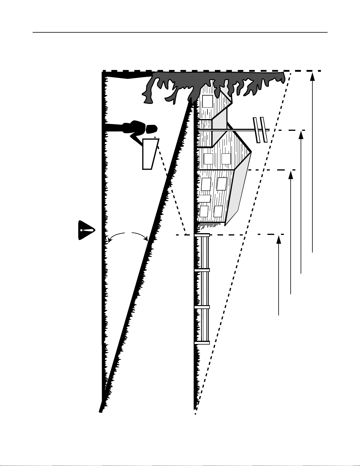
SECTION 2: SLOPE GAUGE
Use this page as a guide to determine slopes where you may not operate safely. Do not operate your lawn mower
on such slopes.
Operate RIDING mowers up and down slopes, never across the face of slopes.
Operate WALK-BEHIND mowers across the face of slopes, never up and down slopes.
Do not mow on inclin es with a s lo pe i n e xces s of 1 5 de gr ees ( a r ise o f approximately 2-1/2 feet every 10 fee t). A ri di ng m owe r could
overturn and cause serio us injur y. If oper ating a walk-be hind mo wer on suc h a slope, i t is ex tremely diffic ult to maint ain your footing
and you could slip, resulting in serious injury.
F
O
L
D
O
N
D
O
T
T
E
D
L
I
N
E
,
R
E
P
R
E
S
E
N
T
I
N
G
A CORNER OF A BUILDING
OR A FENCE POST
SIGHT AND HOLD THIS LEVE L WITH A VERTICAL TREE
A POWER POLE
WARNING
15°
A
1
5
°
S
L
O
P
E
6
Page 7

SECTION 3: ASSEMBLING YOUR LAWN MOWER
IMPORT ANT :
in the engine. Be certain to service engine with gasoline
and oil as instructed in the separate engine manual
before operating your mower.
NOTE: Reference to right or left hand side of the mower
is observed from the operating position.
This unit is shipped without gasoline or oil
Removing Unit From Carton
• Remove staples, break glue on top flaps, or cut
tape at carton end and peel along top flap to open
carton.
• Remove loose parts if included with unit (i.e.,
operator’s manual, oil, etc.)
• Cut along corners, lay carton down flat, and remove
packing material.
• Roll or slide unit out of carton and check carton
thoroughly for loose parts.
Disconnecting Spark Pl ug Wire
• Before setting up your lawn mower, disconnect the
spark plug wire from the spark plug and ground to a
bolt on the engine. See Figure 1.
Stud
Spark Plug
Wire
• Secure the handle assembly by placing the hairpin
clips in the inner hole on weld pins.
• The rope guide is attached to the right side of upper
handle. Loosen the wing nut which secures the
rope guide.
• With the spark plug disconnected and grounded,
hold the blade control handle against the upper
handle and pull the starter rope out of the engine.
Release the blade control handle. Slip the starter
rope into the rope guide and tighten the wing nut.
• Make certain all nuts and bolts are tightened
securely.
Attaching Bag To Mower
• Swing open the chute door on the catcher panel
and hold in this position. See Figure 2.
Hook On
Frame
Grass
Catcher
Frame
Channel On
Mower
Chute
Door
Spark
Plug Wire
Spark Plug
Figure 1
Attaching Handle to Mower
• For shipping purposes, your mower is set with the
rear wheels in the lowest cutting position. Raise the
rear wheels to the highest setting for assembly of
handle.
• Remove the hairpin clips from the outer hole in the
weld pins on the handle mounting brackets.
• Lift the handle and attach by placing the bottom
holes in the lower handle over the weld pins on the
handle mounting brackets. Make sure the lower
handle is seated securely into the handle mounting
brackets.
• Pull up on the upper handle to raise it into the
operating position. Tighten the wing nuts on each
side of the handle.
NOTE: Your mowe r is shipped with the handle in the
higher height position. If you wish to lower the height of
the handle, refer to the Adjustment Section at this time.
Rear Discharge
Chute Assembly
Figure 2
• Slide the frame of the grass catcher down into the
channels on each side of the mower. The hooks on
the frame go over the panel on the discharge chute.
• To remove the grass catcher, hold the chute door
and lift the grass catcher straight up using the
handle.
Converting Mow er To Side Discharge
• Remove the rear d ischar ge chu te as sembl y by
removing two wing nuts. Lift up on the two bottom
corners of the discharge chute assembly and slide
it off the deck.
• Attach the side chute deflector by first placing it
over the rear bolt in the side of the deck. Then slide
the notch in the top of the deflector around the
shoulder bolt on top of the deck.
• Slide the notch in the side of the deflector around
the front bolt in the side of the deck. Secure the
front of the chute deflector to the bolt on the side of
the deck with one wing nut. See Figure 3.
7
Page 8

Chute
Deflector
Shoulder
Bolt
Shoulder Bolt
Mulching Plug
Figure 3
• Secure the ba ck o f the chute d efle ctor i n the sa me
manner. See Figure 4.
Wing Nut
Chute
Deflector
Figure 4
WARNING: Before using your lawn mower,
again refer to the Safety Section in this
manual. Always be careful.
Converting Mower To A Mulcher
• Remove eith er th e rear disc harge chute asse mbly
or the side chute deflector from the mower as
previously instructed.
• Attach the mulching plug by first placing it over the
rear bolt in the side of the deck. Then slide the
notch in the top of the mulching plug around the
shoulder bolt on the top of the deck. Slide the notch
in the side of the mulching plug around the front bolt
in side of the deck and secure using two wing nuts.
See Figure 5.
Wing Nuts
Figure 5
Replacing The Rear Discharge Chute
• Slide the ribs on the discharge chute assembly
under the flange on rear panel as you insert the
side of the discharge chute under the two tabs.
See Figure 6.
Ribs
Flange
Shoulder Bolt
Figure 6
• The edge of the discharge chute assembly goes
under the shoulder bolt on deck. Push down on the
chute assembly and slide the bottom corner slots
over the bolts on side of deck.
• Press down on the disc harge chute assemb ly an d
secure with wing nuts. Make certain wing nuts are
seated properly.
Rear Panel
Tabs
Rear Discharge
Chute Assembly
SECTION 4: KNOW YOUR LAWN MOWER
Read this operator’s manual and safety rules before
operating your lawn mower. Compare the illustrations
in Figure 7 with your lawn mower to familiarize yourself
with the location of various controls and adjustments.
Save this manual for future reference.
8
WARNING: The operation of any lawn
mower can result in foreign objects being
thrown into the operator’s eyes and causing
severe eye damage. Always wear safety
glasses while operatin g the mow er , or w hile
performing any adjustments or repairs on it.
Page 9

Recoil
Starter
Drive Clutch
Cable
Model Series 820 Shown
Figure 7
Recoil Starter
The recoil starter is attached to the right lower handle.
Stand behind the unit and pull the recoil starter to start
the unit. See Figure 7.
Blade Control Handle
The blade control handle is located on the upper handle
of the mower. The blade control handle must be
depressed in order to operate the unit. Release blade
control handle to stop engine and blade. See Figure 7.
WARNING: This blade contro l mechanism
is a safety device. Never attempt to bypass
its operations.
Caster Lock
WARNING: When operating mower on
hills, front wheels should be locked in the
straight ahead position.
The casters can be locked in a straight ahead position
or can be left to swivel freely.
• Lift and place the lock pins in the larger holes to
lock the wheels for straight-ahead operation.
• Place pins in smaller hole s to allow cas ters to rota te
freely for turning.
Blade Control
Handle
Cutting Height
Adjustment Lever
Caster Locks
Cutting Height Adjustment Lever
The cutting height adjustment lever is located above
the left rear wheel. To adjust the cutting height, refer to
the Adjustment Section in this manual. See Figure 7.
Drive Clutch Control (820 Thru 829)
The drive clutch control is located on the upper handle.
Squeeze the drive control to engage the drive system.
Release the clutch control to disengage the drive
system. Release the clutch control to slow down when
approaching an obstacle, making a turn, or stopping.
See Figure 7.
Engine Controls
See the separate engine manual for the location and
function of the controls on the engine.
Stopping Engine
• Release blade control handle to stop the engine
and the blade.
• Disconnect spark plug wire and ground it to the
post on the engine.
SECTION 5: OPERATING YOUR LAWN MOWER
WARNING: Keep hands and feet away
from chute area on the cutting deck. The
operation of any lawn mower can result in
foreign objects being thrown into the
eyes, which can result in severe eye
damage. Always wear safety glasses or
eye shields.
NOTE: For shipping pu rposes your mower is set with
the wheels in a low cutting height position. For best
results raise the cutting position until it is determine
which height is best for your lawn. See the adjustment
section for details.
9
Page 10

Towards Better Mower Performance
1. Read this manual in its entirety before you start
the lawn mower. Instructions given here have
been designed for maintaining safety while
getting the best performance from your mower.
Follow the instructions closely.
2. Pour fresh, clean gasoline into the mower’s gas
tank until the tank is full. Do not use gasoline
that is more than 30 days old.
3. Always use a fuel stabilizer. It will double the life
of the gasoline used.
4. Make sure to connect the mower’s spark plug
wire before trying to start the engine.
5. Add engine oil to the oil fill on the mower engine.
Check the dipstick and add more if necessary.
Remember that the oil level has to touch the fill
line.
6. Locate the primer decal near the primer bulb on
For more details about proper lawn care, visit our website at www.mtdproducts.com
Gas and Oil Fill-Up
Service the engine with gasoline and oil as instructed in
the separate engine manual packed with your mower.
Read instructions carefully.
WARNING: Never fill fuel tank indoors with
engine running or until the engine has
been allowed to cool for at least two
minutes after running.
Before Starting Your Mower (Models 820 Thru
829)
• Attach spark plug wire to spark plug. Make certain
the metal cap on the end of the spark plug wire is
fastened securely over the metal tip on the spark
plug.
• Check for proper drive clutch operation using the
NEUTRA L ADJ UST MEN T TES T.
Neutral Adjustment Test
To perform the neutral adjustment test answer the
following questions.
• With the drive clutch control released, push mower
forward and pull it backward. Does it move freely?
• Squeeze the drive clutch control and pull the
mower backward. Do the rear wheels lock?
• Is the drive clutch control cable free of kinks or
sharp bends?
• If you answered “yes” to all three questions, your
mower passed the test and you can start your
mower.
the engine, and read its instruction. Using your
thumb, press the primer bulb slowly as many
times as the decal advises.
7. Set cutting height adjustment lever to middle
setting and mow a single pass on your lawn;
then adjust to desired height for a closer cut.
8. In heavy growing season, it may be necessary
to mow la wn twi ce we ekly . Clu mps of gras s
clippings left behind on the lawn usually means
that the grass is too high to mulch.
9. Before storing the lawn mower for the winter,
use stabilizer-treated fuel and run the tank dry.
10. Thirty days before start of the new season,
check the air filter, spark plug and blade on the
lawn mower, and replace if needed.
• If you answered “no” to any of the three questions,
you will have to adjust the drive clutch control in the
ADJUSTMENT SECT ION.
Starting Engine
• Prime engine as instructed in the separate engine
manual packed with your unit.
• Your lawn mower is equipped with a constant
speed throttle, which is set at full throttle for best
performance.
• Stand behind the mower and squeeze the blade
control handle against the upper handle.
• Grasp recoil starter handle and pull rope out slowly
until engine reaches the start of compression cycle
(rope will pull slightly harder at this point).
• Pull rope with a rapid, continuous, full arm stroke.
Keeping a firm grip on the starter handle, let the
rope return to the starter slowly.
WARNING: Never operate your unit
without either the side chute deflector or
entire rear discharge chute and grass
catcher assembly in place.
Using Y our Lawn Mow er
Be sure that the lawn is clear of stones, sticks, wire, or
other objects which could damage the lawn mower or
the engine. Such objects could be accidently thrown by
the mower in any direction and cause serious personal
injury to the operator and others.
For best results, do not cut wet grass because it tends
to stick to the underside of the mower, preventing
10
Page 11

proper discharge of grass clippings, and could cause
you to slip and fall. New grass, thick grass, or wet grass
may require a narrower cut.
For a healthier lawn, never cut off more than one-third
of the total length of the grass. Your lawn should be cut
in the fall as long as there is growth. This mower is
designed to be operated at full throttle to give you the
best cut and do the most effective job of mowing or
mulching.
WARNING: If you strike a foreign object,
stop the engine. Remove wire from the
spark plug, thoroughly inspect the mower
for any damage, and repair the damage
before restarting and operating the
SECTION 6: MAKING ADJUSTMENTS
mower. Extensive vibration of the mower during
operation is an indication of damage. The unit
should be promptly inspected and repaired.
Mulching
For effective mulching, do not cut wet grass because it
tends to stick to the underside of the deck, preventing
proper mulching of grass clippings. New or thick grass
may require a narrower cut. The ground speed should
be adjusted to the condition of the lawn. If mowing has
been delayed and the grass has been allowed to grow
in excess of 4”, mulching is not recommended. Mow
using the grass bag to reduce the grass height to 3 1/4”
maximum before mulching.
WARNING: Do not at any time make any
adjustments without first stopping engine
and disconnecting spark plug wire.
Cutting Height Adjustment
The height adjustment handle for the rear wheels is
located on the left side of the deck. The handle may be
placed in one of the six cutting height positions. Push
the handle to the left and then either forward to lower
the cutting height or backward to raise the cutting
height. See Figure 8.
Height Adjustment
Handle
Figure 8
The front wheel cutting height is determine by the
selection of one of the six positions in each caster
assembly.
• To adjust, remove the wing nut from the axle bolt
and slide the axle bolt and spring washer from the
assembly and select a cutting height.
• With the spring washer on the axle bolt, insert the
axle bolt in the desired square hole and through
wheel assembly.
• Secure with wing nut previously removed
NOTE: All wheels mus t be placed in the sa me relative
position. For roug h or uneven lawns , move the height
adjustment lever to a higher position. This will help stop
scalping.
Handle Height Adjustment
Your mower is shipped with the handle in the higher
height position. To lower the height proceed as follows:
• Remove the start er ro pe fr om th e rope guid e.
• Remove the upper handle by removing the hand
knobs and carriage bolts. Lay the upper handle out
of the way, being careful not to bend or kink the
cables.
• Remove the hairpin clips from the weld pins on the
handle brackets. Press out on the legs of the lower
handle. Remove lower handle from the mower.
• Turn lower handle around so the notch on the
bottom of the lower handle is facing forward.
Reassemble, placing the bottom holes in the
handle over the weld pins in the handle mounting
bracket.See Figure 9.
• Reassemble the upper handle to the lower handle.
• Place the hairpin clips in the inner holes in the weld
pins and attach the starter rope as instructed in the
Assembly Section.
Notch
Lower Handle
Figure 9
11
Page 12

Drive Clutch Control Adjustment (Models 820
Thru 829)
Use the adjustment wheel located on the underside of
the clutc h cont rol h ousin g to t ight en the dri ve bel t, if
mower does not self-propel with the drive clutch control
engaged, or if drive belt is slipping (unit hesitates while
Adjustment
Wheel
engine maintains the same speed). See Figure 10.
In addition, the adjustment wheel may also be used to
determine the position in which the drive clutch control
is engaged. If it is more comfortable to have the drive
engaged with the lever further away from the handle,
tighten the drive belt.
Make certain to retest the unit for neutral as instructed
in the Operation Section. Move the adjustment wheel in
the opposite direction to loosen the drive belt if
necessary.
NOTE: For some pe ople the drive clutch control m ay
Engine Adjustments
See the separate engine manual packed with your unit
for adjustments to the engine.
not be in a comfortable position. You can adjust the
handle out by tightening the adjustment wheel.
SECTION 7: MAINTAINING YOUR LAWN MOWER
Bottom View
Upper
Handle
Drive Clutch
Control
Figure 10
Customer Responsibilities
MAINTENANCE
SCHEDULE
Lubricate wheels
T
Lubricate blade control
C
U
D
Lubricate Caster Assembly
O
R
Blade care
P
Clean deck
Change oil
Replace air filter
E
N
I
Clean engine
G
N
E
Check spark plug
Check spark arr ester (if any)
s
s
e
s
u
h
c
a
e
r
e
t
f
A
E
s
r
u
o
h
5
2
y
r
e
v
u
o
h
0
5
y
r
e
v
E
E
r
r
u
o
h
0
0
1
y
r
e
v
O
n
e
o
g
s
a
r
a
o
e
t
s
s
a
e
r
e
o
f
c
e
n
B
SERVICE
DATES
General Recommendations
• Always observe safety rules when performing any
maintenance.
• The warran ty on this lawn m ower does n ot co ver
items that have been subjected to operator abuse
or negligence. To receive full value from the
warranty, operator must maintain the lawn mower
as instructed in this manual.
• Changing of engine governed speed will void
engine wa rrant y.
• Some adjustm ents will have to be m ade
periodically to maintain your unit properly. All
adjustments in the Making Adjustments section of
this manual should be checked at least once each
season.
12
Page 13

• Periodically check all fasteners and make sure
these are tight.
• Follow the maintenance schedule under Customer
Responsibilities to get quality performance from
your lawn mower.
accumulate, it will invit e rust and co rrosio n, and may
prevent proper mulching, discharge, or bagging. The
deck may be cleaned by tilting the mower and scraping
clean with a suitable tool (make certain the spark plug
wire is disconnected).
Lubrication
WARNING: Always stop engine and
disconnect spark plug wire before
cleaning, lubricating or doing any kind of
service work on the lawn mower.
Blade Control: Lubricate the pivot points on the blade
control handle at least once a season with light oil. The
blade control must operate freely in both directions.
Refer to Figure 7.
Wheels: Lubricate the wheels at least once a season
with light oil (or motor oil). If the wheels are removed for
any reason, lubricate the surface of the axle bolt and
inner surface of the wheel with light oil.
Caster Assembly: Grease fittings are provided for
easy lubrication of the swivel pins located on the front
caster assembly. Refer to Figure 7.
Engine: Follow the separate engine manual packed
with you unit for lubrication instructions.
Maintenance
NOTE: When tipp ing the unit, empty the fuel tank and
keep the spark plug side of engine up. Never tip the
mower more than 90 degrees and do not leave the
mower tipped for any l ength of time. Oil can drain into
the upper part of the engine causing a starting problem.
IMPORTANT:
pressure washer or garden hose to clean your unit. The
use of wate r will resu lt in sh orte n life and r educe
serviceability.
We do not recommend the use of a
Cutting Blade Removal, Replacement, and Sharpening
• When removing the cutting blade for sharpening or
replacement, protect your hands with a pair of
heavy gloves or use a heavy rag to hold the blade.
• Remove the bolt and the blade bell support which
hold the blade and the blade adapter to the engine
crankshaft. See Figure 11.
• Remove the blade and the adapter from the
crankshaft.
WARNING: Periodically inspec t the blade
adapter for cracks, esp ecially if you str ike
a foreign object. Replace when necessary.
Blade
Adapter
Blade Bell
Support
Hex Bolt
Engine
Refer to the separate engine manual for all engine
maintenan ce instr uctio ns.
• Maintain engine oil as instructed in the separate
engine manual packed with your unit.
• Service air cleaner every 25 hours under normal
conditions. Poor engine performance and flooding
usually indicate that the air cleaner should be
serviced. To service the air cleaner, refer to the
separate engine manual packed with your unit.
• The spark plug should be cleaned and the gap
reset once a season. Spark plug replacement is
recommended at the start of each mowing season.
• Clean the engine regularly with a cloth or brush.
Keep the cooling system (blower housing area)
clean to permit proper air circulation which is
essential to engine performance and life. Be certain
to remove all grass, dirt, and combustible debris
from muffler area.
Deck
The underside of the mower deck should be cleaned
after each use to prevent a buildup of grass clippings,
leaves, dirt, or other matter. If this debris is allowed to
Figure 11
When sharpening the blade, follow the original angle of
grind as a guid e. It is ex tre mely i mport ant t hat each
cutting edge receives an equal amount of grinding to
prevent an unbalanced blade. An unbalanced blade will
cause excessive vibration when rotating at high
speeds. It may cause damage to the mower, and could
break causing personal injury.
The blade can be tested by balancing it on a round
shaft screwdriver. Remove metal from the heavy side
until it balances evenly. It is recommended that the
blade always be removed from the adapter when
testing for balance. Before reinstalling the blade and
the blade adapter to the unit, lubricate the engine
crankshaft and the inner surface of the blade adapter
with light oil.
• Be sure to install the blade with the side of the
blade marked “Bottom” (or with part numb er) facing
the ground when the mower is in the operating
position.
13
Page 14

• Slide the blade adapter onto the engine crankshaft.
• Place the blade on the adapter. Be certain the
blade is aligned and seated on the blade adapter
flanges.
• Place blade bell support on blade. Make sure the
notches on the blade bell support are aligned with
small holes in the blade.
• Replace hex bolt and tighten hex bolt to torque: 450
in. lbs. min., 600 in. lbs. max.
NOTE: To ensure safe operation of your mower, the
blade bolt must be checked periodically for correct
torque.
Drive Belt Removal and Replacement (Models 820 Thru
829)
• Disconnect the spark plug wire and ground it
against the engine.
• Drain the fuel tank or place a piece of plastic
beneath the cap to prevent gasoline leakage.
• Remove the grass b ag, r ear di scharg e chu te
assembly, and catcher panel.
• Remove the tr ansmissi on be lt cove r by rem oving
three bol ts. Se e Fi gure 1 2.
Transmission
Belt Cover
Remove
Bolt
Remove
Bolts
Figure 12
• Tip the mower on its side and block securely.
• Remove the belt guard under the deck by removing
two self-tapping screws. See Figure 13.
Remove
Bolt
• Loosen the bolt which secures the idler pulley so
you can remove the belt from between the idler
pulley and the belt guard on the idler pulley bracket.
See Figure 14.
Belt
Guard
Idler Pulley
Pulley
Figure 14
• Remove the belt from the transmission pulley by
pulling it underneath the pulley.
• Remove the belt from around the blade.
NOTE: Before reassembling, you should remove the
idler pulley from the idler bracket to clean and grease
the needle bearing inside the pulley using an allpurpose grease. When reassembling, cupped side of
washer must be against the idler bracket.
• Reassemble new belt following the previous
instructions in re verse orde r.
• When reassembling the transmission belt cover, be
certain the belt guard on the transmission cover is
approximately 1/8” away from the belt.
• Make certain to tighten all nuts and bolts securely.
Storing your Lawn Mower
The following steps should be taken to prepare your
lawn mower for storage.
• Clean and lubricate mower thoroughly as described
in the lubrication instructions.
IMPORT ANT :
pressure washer or garden hose to clean your unit.
We do not recommend the use of a
Remove
Center Bolt
Figure 13
Inside Belt
Guard
• Refer to engine manual for correct engine storage
instructions.
• Coat mower’s cutting blade with chassis grease to
prevent rusting.
• Store mower in a dry, clean area. Do not store next
to corrosive materials, such as fertilizer.
NOTE: When storing any type of power equipment in a
poorly ventilated or metal storage shed, care should be
taken to rust-proof the equi pment. Using a light oil or
silicone, coat the equipment, e specially cab les and all
moving parts.
14
Page 15

SECTION 8: TROUBLESHOOTING
Problem Cause Remedy
Engine fails to start 1. Blade control handle disengaged.
2. Spark plug wire disconnected.
3. Fuel tank empty or stale fuel.
4. Blocked fuel line.
5. Faulty spark plug.
6. Engine flooded
Engine runs er ratic 1. Spark plug wire loos e.
2. Blocked fuel line or stale fuel.
3. Vent in gas plugged.
4. Water or dirt in fuel system.
5. Dirty air cleaner.
6. Carburetor out of adjustment.
Engine overheats 1. Engine oil level low.
2. Air flow restrict ed.
3. Carburetor not adjusted properly.
Occasional skip (hesitates)
at high speed
Idles poorly 1. Spark plug fouled, faulty or gap too
Excessive vibration 1. Cutting blade loose or unbalanced.
Mower will not mulch grass 1. Engine speed too low.
Uneven cut 1. Wheels not positioned correctly.
Wheels will not propel
(Models 820 thru 829)
NOTE: For repairs beyond the minor adjustments listed above, contact your nearest authorized service dealer.
1. Spark plug gap too close. 1. Adjust gap to .030”.
wide.
2. Carburetor improperly adjusted.
3. Dirty air cleaner.
2. Bent cutting blade.
2. Wet grass.
3. Excessively high grass.
4. Dull blade.
2. Dull blade.
1. Belt not installed properly.
2. Debris clogging mechanism.
1. Engage blade control handle.
2. Connect wire to spark plug.
3. Fill tank with clean, fresh gasoline.
4. Clean fuel line.
5. Clean, adjust gap, or replace.
6. Crank engine with throttle in FAST
position.
1. Connect and tighten spark plug wire.
2. Clean fuel line; fill tank with clean, fresh
gasoline
3. Clear vent.
4. Drain fuel tank. Refill with fresh fuel.
5. Clean air cleaner.
6. Adjust carburetor.
1. Fill crankcase with proper oil.
2. Remove blower housing and clean.
3. Adjust carburetor.
1. Reset gap to .030” or replace spark
plug.
2. Adjust carburetor.
3. Clean air cleaner.
1. Tighten blade and adapter. Balance
blade.
2. Replace blade.
1. Set throttle between 3/4 and full throttle.
2. Do not mow when grass is wet; wait
until later to cut.
3. Mow once at a high cutting height, then
mow again at desired height or make a
narrower cutting path.
4. Sharpen or replace blade.
1. Place all four wheels in same height
position.
2. Sharpen or replace blade.
1. Check belt for proper pulley installation.
2. Clean out debris.
15
Page 16

Model Series 810 Thru 829
62
39
32
60
49
50
60
40
89
7
1
72
62
23109
110
18
78
90
107
108
18
50
49
109
46
23
110
44
40
77
C
39
B
32
41
36
109
93
84
58
66
21
59
73
67
55
68
102
86
85
92
56
16
Page 17

Model Series 810 Thru 829
REF.
NO. PART NO. DESCRIPTION
1. 720-0294 Foam Handle
2. 747-0824 Control Lev er
3. 731-1023 Rear Discharge Chute Ass’y
4. 710-0605 Oval C-Sunk Screw (If Equipped)
5. 646-0875 Throttle Body (If Equipped)
6. 736-0501 Spring Washer .66” (If Equipped)
7. 712-0324 Hex L-Nut 1/4-20 (If Equipped)
8. 746-0876 Throttle Lever (If Equipped)
9. 710-1205 Rope Guide
10. 720-0279 Wi ng Nut 1/4-2 0
11. 731-1426 Hub Cap Spoke
12. 710-0896 Truss Machine Screw 1/4-14 x .625
13. 736-0258 Flat Washer .383” ID x 1” OD
14. 749-0439C Upper Handle †
749-0438B Upper handle ††
15. 16129A Panel Support Bracket
16. 16862 Rear Catcher Pane l Ass’y
17. 17095A Rear Discharge Door
18. 731-1886 Hub Cap Spoke w/Hole
19. 732-0483A Torsion Spring
20. 747-0514 Pivot Pin
21. 710-0134 Carriage Bolt 1/4-20 x .62”
22. 710-0924 Truss Machine Screw 1/4-20 x .75”
23. 747-0924 Lock Pin
24. 738-0704 Shoulder Bolt .312 x .18
25. 710-0751 Hex Bolt 1/4-20 x .62”
26. 712-0287 Hex Nut 1/4-20
27. 736-0270 Bell Washer 1/4” †
28. 736-0329 Lock Washer 1/4”
29. 747-0705 Front Gr as s Catc her Frame
30. 722-0139 Foam Strip
31. 731-1059 SP Control Cover †
32. 726-0214 Push Cap
33. 712-0397 Wi ng Nut w/ Washer
34. 746-06 74 Throttle Control Wire 61”
35. 749-0907A Lower Handle
36. 682-9021A Caster Ass’y LH
682-9020A Caster Ass’y RH
37. 710-1237 Hex Tap Screw #10-32 x .62”
38. 664-0082 Grass Bag
39. 712-0397 Wi ng Nut
40. 682-9026 Caster Bracket Ass’y LH
682-9024 Caster Bracket Ass’y RH
41. 736-0204 Flat Washer .344” ID x .62”
42. 17055B Chain - Axle Ass’y †
43. 710-0352 Hex Tap Screw 1/4” x .38”
44. 736-0232 Wave Washer
45. 710-0776A Hex Tap Screw 1/4 x .62”
46. 711-1146 Caster Axle
47. 712-0296 Hex Lock Nut 3/8-24 †
48. 713-0353 #48 Chain .500” Pitch x 30 Links †
49. 737-3000 Lube Fitting
50. 736-0931 Fl at Washer
REF.
NO. PART NO. DESCRIPTION
51. 731-1488 Rear Flap †
52. 726-0240 Cable Tie
53. 751B213146 Cable Clamp
54. 710-1025 Hex Screw #12 x 1.25”
55. 753-0609 Blade Adapter Kit
56. 742-0641 21” Standard Blade
742-0741 21” Mulching Blade
57. 731-0564 Mulching Plug
58. 736-0524A Blade Bell Support
59. 710-1044 Hex Bolt 3/8-24 x 1.5”
60. 741-0685 Fl ange Bearing
61. 748-0190 Spacer .513” ID x .69” †
62. 736-0366 Flat Washer 5/8 ID x 1.0 OD
64. 16136C RH Hand le Whe el B ra cket Ass’y
65. 682-0532 LH Handle Wheel Bracket Ass’y
66. 710-0260 Carriage Bolt 5/16-18 x .62”
67. 710-0603 Hex Tap Screw 5/16-18
68. 710-0654A Hex Tap Screw 3/8-16
69. 712-0267 Hex Nut 5/16-18
70. 720-0223 Grip
71. 732-0606 Height Adjuster Lever
72. 746-0883 Throttle Housing w/o Lever
73. 736-0242 Bell Washer 5/16”
74. 750-0736 Spacer
75. 750-0624 Shoulder Spacer .50”
76. 719-0279 Rope Guide
77. 726-0 233 Bo lt Retainer
78. 734-1857 Front Wheel Ass’y Comp
79. 741-0486B Bearing 1/2” ID
80. 738-0137 Shoulder Screw
81. 748-0188B Pawl
82. 734-2005 Rear Wheel Ass’y Comp †
734-2004 Rear Wheel Ass’y Comp ††
83. 726-0175 Clamp
84. 736-0514 Fl at Washer †
85. 736-0513 Spring Washer .89” ID †
86. 748-0358 Crankshaft Spacer †
87. 731-0880 Panel Clip
88. 712-0414 Weld L-Nut 1/4-20
89. 710-1270 Screw 1/4-20 x 20
90. 714-0104 Cotter Pin
91. 720-0314 Hand Knob
92. 756-0962 Pulley Half-Upper †
93. 756-0961 Pulley Half-Lower †
94. 710-0578 Machine Screw 1/4-20
95. 746-0710A Drive Cable †
96. 754-0343 V-Belt †
97. 712-0271 Sems Nut 1/4-20
98. 731-0801 Bag Handle
100. 714-0104 Hairpin Clip
102. 782-0098 21” Deck †
782-0112 21” Deck ††
106. 711-0313 Sleeve
17
Page 18

REF.
NO. PART NO. DESCRIPTION
107. 736-0264 Flat Washer .330 ID x .630 OD
108. 732-0306 Compression Spring
109. 710-0260 Carriage Bolt 5/16-18 x .62
110. 712-3004A Flange Lock Nut 5/16-18
114. 731-1057 SP Control Cover †
115. 731-1058 SP Control Cover †
116. 731-0620 Control Lever †
117. 720-0190 Door Grip
118. 710-1667A C Sunk Tap Screw #10-16 x .625 †
119. 16855 Pawl Plate
121. 710-1174 Curved Carriage Bolt 5/16-18 x 2”
122. 711-0805 Shoulder Pin 3/8-24 x 1.43”
123. 736-0169 Lock Washer 3/8” ID
129. 746-0922 Control Cable
130. 748-0318 Ratchet Wheel 1.62” OD †
131. 714-0115 Cotter Pin †
132. 712-0711 Hex Jam Nut 3/8-24
† Models 820 Thur 829
†† Models 810 Thru 819
REF.
NO. PART NO. DESCRIPTION
133. 731-0884 Side Chute Deflector Ass’y
134. 741-0522 Hex Flange Bearing †
135. 811-00185 Throttle Box Comp (If Equipped)
136. 10622B Nylon Spring †
138. 17053A Chain Cover †
140. 710-0599 Hex Tap Screw 1/4-20 x .50” †
144. 736-0300 Flat Washer †
147. 738-0719A Rear Shaft Ass’y †
148. 741-0324 Hex Flange Bearing .506” ID †
149. 736-0160 Flat Washer .531” x .930” †
152. 710-0751 Hex Bolt 1/4-20 x .62
153. 618-0055 Transmission Comp †
154. 16500A Hex Bearing Cup
155. 710-0429 Hex Tap Screw #10 x .38
161. 749-0764A Rear Catcher Frame
163. 710-0352 Hex Tap Screw 1/4 x .38”
164. 782-7555 Mulching Baffle
18
Page 19

Model Series 820 Thru 829
REF.
NO. PART NO. DESCRIPTION
1. 710-1062 Hex Bolt w/Patch 1/4-20 x 1.25”
2. 726-0329 L-Washer 1/4” ID
3. 717-0418A Upper Housing Half
4. 713-0400 #48 Sprocket 7 Tooth x 1/2 Pitch
5. 736-0336 Flat Washer 5/8” ID x.030 OD
6. 741-0 413 Hex Flange Bearing .631” ID
7. 16500A Hex Bearing Cup
8. 736-0314 Thrust Washer .382” ID x .70” OD
9. 741-0479 Thrust Bearing .375” ID x .812” OD
10. 782-7569 Belt Keeper
11. 717-1216 11 Tooth Helical Gear
12. 748-0208A Flange Bearing
13. 721-0212 Oil Seal
15. 756-0330A Pulley 5.06” ID
16. 736-0270 Bell Washer .265” ID x .75” OD
17. 712-0351 Hex Nut 1/4-28 LH Thread
18. 738-0440 Shoulder Spacer .375”
19. 736-0344 Flat Washer .390” ID x 1.0” OD
20. 738-0826 Shoulder Bolt .375” x .40”
21. 756-0558 Idler Pulley 1.50”
22. 741-0556 Needle Bearing .375” x .31”
23. 736-0270 Bell Washer .265” ID x .75”
REF.
NO. PART NO. DESCRIPTION
24. 782-7570 Idler Bracket Ass’y
25. 712-0138 Hex Lock Nut 1/4-28
26. 732-0357A Extension Spring 1.12”
27. 717-0419B Lower Housing Half
28. 741-0415 Fl ange Bearing .56”
29. 717-0422A 33 Tooth Helical Gear
30. 741-0414 Fl ange Bearing .629”
31. 721-0213 Oil Seal .625”
32. 738-0607B Gear Sprocket Shaft
33. 736-0722 Lock Washer #10
34. 710-0436 Hex Tap Screw #10 x .62”
35. 736-0410 Hex Washer .26” x .88”
36. 17718 Transmission be lt Guard
39. 710-0599 Hex Tap Screw 1/4 x .50”
40. 710-0896 Hex Tap Screw 1/4 x .62”
41. 712-0287 Hex Nut 1/4-20
42. 736-0270 Bell Washer .265” ID x .75”
43. 736-0329 Lock Washer 1/4” ID
44. 746-0710A SP Cable - 48”
45. 747-0549 SP Be lt Guard
618-0055 Transmission Complete
19
Page 20

MANUFACTURER’S LIMITED WARRANTY FOR:
The limited warranty set for th below is given by MTD PRODUCTS INC (“MTD”) with respect to new merchandise purchased and used in the United States, its possessions and
territories.
MTD warrants this product against defects in material and
workmanship for a period of two (2) years commencing on
the date of original purchase and will, at its option, repair or
replace, free of charge, any part found to be defective in
material or workmanship. This limited warranty shall only
apply if this product has been operated and maintained in
accordance with the Operator’s Manual furnished with the
product, and has not been subject to misuse, abuse, commercial use, neglect, accident, improper maintenance, alteration, vandalism, theft, fire, water or damage because of
other peril or natural disaster. Damage resulting from the
installation or use of any accessory or attachment not
approved by MTD Products Inc. for use with the product(s)
covered by this manual will void your warranty as to any
resulting damages.
Normal wear parts or components thereof are subject to separate terms as follows: All normal wear part or component
failures will be covered on the product for a period of 90 days
regardless of cause. After 90 days, but within the two year
period, normal wear part failures will be covered ONLY IF
caused by defects in material or workmanship of OTHER
component parts. Normal wear parts and components
include, but are not limited to, belts, blades, blade adapters,
grass bags, rider deck wheels, seats, snow thrower skid
shoes, shave plates and tires. Batteries are covered by a 90day limited replacement warranty.
HOW TO OBTAIN SERVICE: Warrant y ser vice i s availabl e,
WITH PROOF OF PURCHASE THROUGH YOUR LOCAL
AUTHORIZED SERVICE DEALER. To locate the dealer in
your area, please check for a listing in the Yellow Pages or
contact the Customer Service Depar tment of MTD PRODUCTS INC by calling 1-800-800-7310 or writing to P.O. Box
368022, Cleveland, Ohio 44136-9722.
This limited warranty does not provide coverage in the
following cases:
a.The engine or component parts thereof. These items
carry a separate manufacturer’s warranty. Please refer to
the applicable manufacturer’s warranty on these items.
b.Log sp li tter p um ps, valves and cylinders have a se par ate
one year warranty.
c. Routine maintenance items such as lubricants, filters,
blade sharpening and tune-ups, or adjustments such as
brake adjustments, clutch adjustments or deck adjustments; and normal de terioration of the exterior finish due
to use or exposure.
d.MTD does not extend any warranty for products sold or
exported outside of the United States of America, its
possessions and territories, except those sold through
MTD’s authorized channels of export distribution.
No implied warranty, including any implied warranty of
merchantability or fitness for a particular purpose,
applies after the applicable period of express written
warranty above as to the parts as identified. No other
express warranty or guaranty, whether written or oral,
except as mentioned above, given by any person or
entity, including a dealer or retailer, with respect to any
product shall bind MTD. During the period of the Warranty, the exclusive remedy is repair or replacement of
the product as set forth above. (Some states do not allow
limitations on how long an implied warranty lasts, so the
above limitation may not apply to you.)
The provisions as set forth in this Warranty provide the
sole and exclusive remedy arising from the sales. MTD
shall not be liable for incidental or consequential loss or
damages including, without limitation, expenses
incurred for substitute or replacement lawn care services, for transportation or for related expenses, or for
rental expenses to temporarily r eplace a warranted product. (Some states do not allow the exclusion or limitation of
incidental or consequential damages, so the above exclusion
or limitation may not apply to you.)
In no event shall recovery of any kind be greater than the
amount of the purchase price of the product sold. Alteration
of the safety features of the product shall void this Warranty.
You assume the risk and liability for loss, damage, or injury to
you and your property and/or to others and their property
arising out of the use or misu se or ina bility to use the produc t.
This limited warranty shall not extend to anyone other than
the original purchaser, original lessee or the person f or whom
it was purchased as a gift.
How State Law Relates to this Warranty: This limited warranty gives you specific legal rights, and you may also have
other rights which vary from state to state.
 Loading...