

Page 1

®
OPERATOR'S MANUAL
Leaf Blowers
Model Series 650
IMPORTANT: READ SAFETY RULES AND INSTRUCTIONS CAREFULLY
Warning: This unit is equipped with an internal combustion engine and should not be used on or near any unimproved forest-
covered, brush-covered or grass-covered land unless the engine's exhaust system is equipped with a spark arrester meeting
applicable local or state laws (if any). If a spark arrester is used, it should be maintained in effective working order by the operator.
In the State of California the above is required by law (Section 4442 of the California Public Resources Code). Other states may have
similar laws. Federal laws apply on federal lands. A spark arrester for the muffler is available through your nearest engine authorized
service dealer or contact the service department, P.O. Box 368022 Cleveland, Ohio 44136-9722.
MTD PRODUCTS INC. P.O. BOX 368022 CLEVELAND, OHIO 44136-9722
PRINTED IN U.S.A.
FORM NO. 770-10191B
(2/01)
Page 2
TABLEOFCONTENTS
Content Page
Important Safe Operation Practices ................................................................... 3
Assembling Your Leaf Blower ............................................................................ 5
Operating Your Leaf Blower ............................................................................... 6
Maintaining Your Leaf Blower ............................................................................ 7
Troubleshooting ................................................................................................. 7
Parts List ............................................................................................................ 14
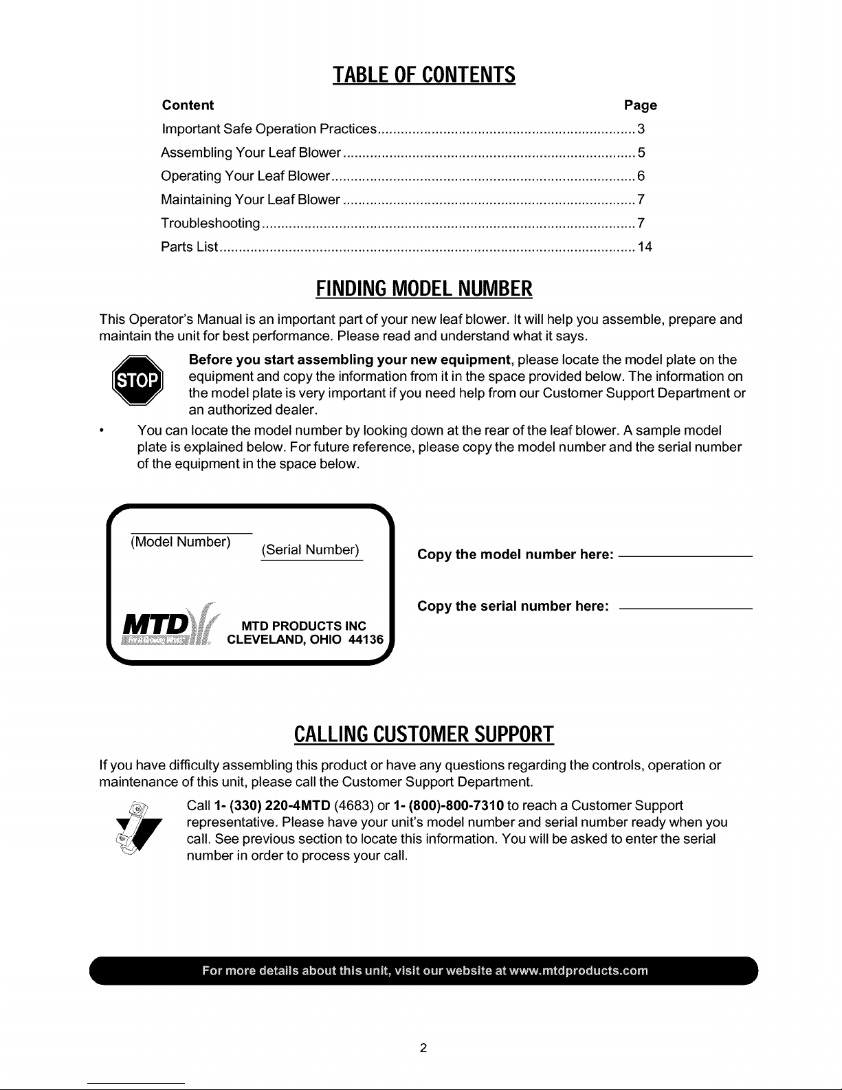
FINDINGMODELNUMBER
This Operator's Manual is an important part of your new leaf blower. It will help you assemble, prepare and
maintain the unit for best performance. Please read and understand what it says.
Before you start assembling your new equipment, please locate the model plate on the
equipment and copy the informationfrom it in the space provided below. The information on
the model plate is very important if you need help from our Customer Support Department or
an authorized dealer.
You can locate the model number by looking down at the rear of the leaf blower. A sample model
plate is explained below. For future reference, please copy the model number and the serial number
of the equipment in the space below.
r
(Model Number)
(Serial Number)
MTD PRODUCTS INC
CLEVELAND, OHIO 44136
Copy the model number here:
Copy the serial number here:
CALLINGCUSTOMERSUPPORT
If you have difficulty assembling this product or have any questions regarding the controls, operation or
maintenance of this unit, please call the Customer Support Department.
Call 1- (330) 220-4MTD (4683) or 1- (800)-800-7310 to reach a Customer Support
representative. Please have your unit's model number and serial number ready when you
call. See previous section to locate this information. You will be asked to enter the serial
number in order to process your call.
Page 3

SECTION1: IMPORTANTSAFEOPERATIONPRACTICES
WARNING: This symbol points out important safety instructions which, if not followed, could
endanger the personal safety and/or property of yourself and others. Read and follow all instructions in
this manual before attempting to operate this machine. Failure to comply with these instructions may
result in personal injury. When you see this symbol - heed its warning.
WARNING: Engine Exhaust, some of its constituents, and certain vehicle
components contain or emit chemicals known to State of California to cause cancer
and birth defects or other reproductive harm.
DANGER: This machine was built to be operated according to the rules for safe operation in this
manual. As with any type of power equipment, carelessness or error on the part of the operator can
result in serious injury. This machine is capable of amputating hands and feet and throwing objects.
Failure to observe the following safety instructions could result in serious injury or death.
GeneralOperation
1. Read this operator's manual carefully in its entirety
before attempting to assemble this machine. Read,
understand, and follow all instructions on the machine
and in the manual(s) before operation. Be completely
familiar with the controls and the proper use of the
machine before operating it. Keep this manual in a safe
place for future and regular reference and for ordering
replacement parts.
2. Your leaf blower is a powerful tool, not a plaything.
Therefore, exercise extreme caution at all times. Your
unit has been designed to perform one job; to blow
leaves. Do not use it for any other purpose.
3. Never allow children under 14 to operate the unit.
Children 14 years and older should only operate under
close parental supervision. Only responsible individuals
who are familiar with these rules of safe operation should
be allowed to use your unit.
4. Keep the area of operation clear of all persons,
particularly small children and pets. Stop the engine
when they are in the vicinity of the unit.
5. Always wear safety glasses or safety goggles during
operation and while performing an adjustment or repair,
to protect eyes from debris or foreign objects that may be
thrown from machine.
6. Wear close fitting slacks and shirt. Shirt and slacks that
cover the arms and legs are recommended. Do not wear
loose fitting clothes or jewelry and secure hair so it is
above shoulder length. They can be caught in moving
parts.
7. Do not operate the unit while under the influence of
alcohol or drugs.
8. Never place your hands or any part of your body or
clothing near rotating parts. Keep clear of the discharge
opening at all times. Never insert your hands, fingers,
feet, or any other part of your body or clothing into the
discharge or air intake openings as the rotating impeller
inside the housing can cause serious injury.
9. Never operate unit without directional discharge chute
and plastic impeller guard properly affixed to unit. These
devices shield the operator from accidental contact with
the rotating impeller.
10. Keep all guards and safety devices in place and
operating properly.
11. Exercise caution when operating blower. Do not allow the
discharge to point in the direction of bystanders or pets.
12. If your machine should start making an unusual noise or
vibration, immediately stop the engine, disconnect the
spark plug wire and move the wire away from the spark
plug. Allow the machine to stop and take the following
steps:
a. Inspectfordamage.
b. Repair or replace any damaged parts.
c. Check for any loose parts and tighten to assure
continued safe operation.
13. Muffler and engine become hot and can cause a burn. Do
not touch.
14. Do not allow leaves or other debris to build up on
engine's muffler. The debris could ignite and cause a fire.
15. Do not operate engine if air cleaner or cover over
carburetor air intake is removed, except for adjustment.
Removal of such parts could create a fire hazard.
16. Only use accessories approved for this machine by the
manufacturer. Read, understand, and follow all
instructions provided with the approved accessory.
17. Only operate unit in good daylight. Do not operate unit at
night or in dark areas where your vision may be impaired.
18. If situations occur which are not covered by this manual,
use care and good judgment. Contact your dealer for
assistance.
Children
Tragic accidents can occur if the operator is not alert to the
presence of small children. Children are often attracted to the
blowing activity. Never assume that children will remain
where you last saw them.
1. Keep children out of the work area and under the
watchful eye of a responsible adult other than the
operator.
2. Be alert and turn the unit off if a child enters the area.
3. Never allow children under the age of 14 to operate the
leaf blower.
Page 4
Service
1. Use extreme care in handling gasoline and other fuels.
They are extremely flammable and the vapors are
explosive.
2. Store fuel and oil in approved containers, away from heat
and open flame, and out of the reach of children.
3. Check and add fuel before starting the engine. Never
remove gas cap or add fuel while the engine is running.
Allow engine to cool at least two minutes before refueling.
4. Replace gasoline cap securely and wipe off any spilled
gasoline before starting the engine as it may cause a fire
or explosion.
5. Extinguish all cigarettes, cigars, pipes and other sources
of ignition.
6. Never refuel unit indoors because flammable vapors will
accumulate in the area.
7. Never store the machine or fuel container inside where
there is an open flame or spark such as a gas hot water
heater, clothes dryer or furnace.
8. Never run your machine in an enclosed area as the
exhaust from the engine contains carbon monoxide,
which is an odorless, tasteless and deadly poisonous
gas.
9. To reduce fire hazard, keep engine and muffler free of
leaves, grass, and other debris build-up.
10. Clean up fuel and oil spillage. Allow unit to cool at least 5
minutes before storing.
11. Before cleaning, repairing, or inspecting, make certain
the impeller and all moving parts have stopped.
Disconnect the spark plug wire and keep wire away from
spark plug to prevent accidental starting. Do not use
flammable solutions to clean air filter.
12. Keep all nuts, bolts, and screws tight to be sure the
equipment is in safe working condition.
13. Never tamper with safety devices. Check their proper
operation regularly.
14. Do not alter or tamper with the engine's governor setting.
The governor controls the maximum safe operating
speed of the engine. Overspeeding the engine is
dangerous and will cause damage to the engine and to
other moving parts of the machine.
_ ARNING - YOUR RESPONSIBILITY: Restrict the use of this power machine to persons who read,
understand and follow the warnings and instructions in this manual and on the machine.
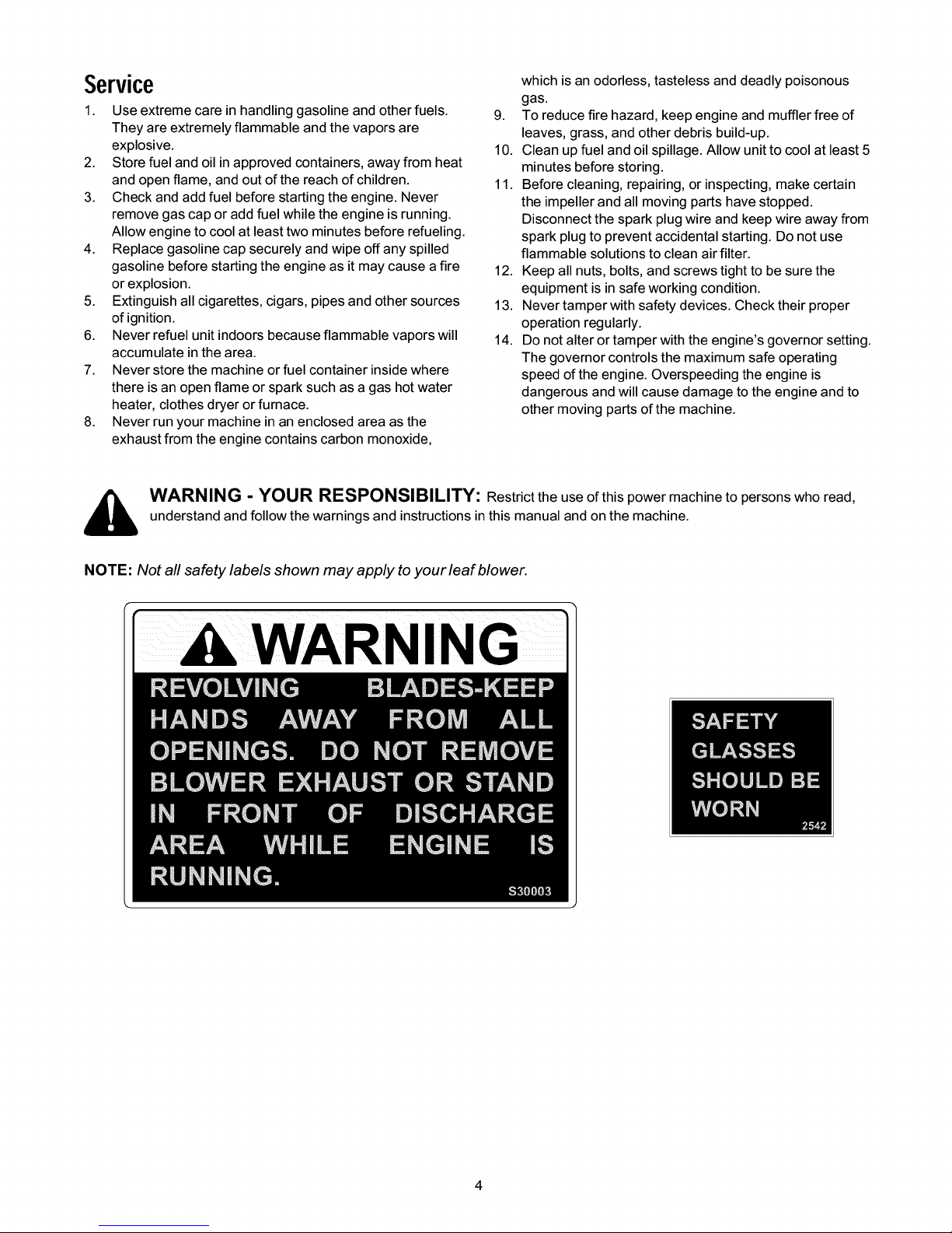
NOTE: Not all safety labels shown may apply to your leaf blower.
WARNING
Page 5

SECTION2: ASSEMBLINGYOURLEAFBLOWER
IMPORTANT:This unit is shipped without gasoline or oil
in the engine. Be certain to service engine with gasoline
and oil as instructed in the separate engine manual
before operating your unit.
NOTE: Reference to right or left hand side of the leaf
blower is observed from the operating position.
RemovingUnitFromCarton
• Remove staples, break glue on top flaps, or cut
tape at carton end and peel along top flap to open
carton.
• Remove loose parts if included with unit (i.e.,
operator's manual, etc.)
• Cut along corners, lay carton down flat, and remove
packing material.
• Roll or slide unit out of carton and check carton
thoroughly for loose parts.
LoosePartsInCarton
• Upper Handle
• Directional Discharge
• Hardware Pack
• Operator's Manual
Curved Head
Lower Handle
Figure 1
AttachingTheDirectionalDischarge
(HardwareB)
• Slip end of directional discharge over chute
opening and secure with the hex sems bolts.
See Figure 2.
HardwarePack
This leaf blower isshipped with the following loose
parts in the hardware pack:
Hardware A
• Curved Head Bolts (710-1174)
• Saddle Washers (736-0451)
• Handle Knobs (720-0241)
Hardware B
• Hex Sems Bolts (710-0259)
DisconnectingSparkPlugWire
,_ WARNING: Before setting up your leaf
blower, disconnect the spark plug wire
from the spark plug and ground against
the engine,
lal Discharge
Figure 2
AttachingTheUpperHandle(HardwareA)
• Place the upper over the lower handle, aligningthe
holes in the upper handle with the middle holes in
the lower handle. See Figure 2.
• Secure with the curved head bolts,saddle washers,
and handle knobs.
Page 6

SECTION3: OPERATINGYOURLEAFBLOWER
WARNING: Read, understand, and follow
all instructions and warnings on the
machine and in this manual before
operating,
GasAndOilFill-Up
Service the engine with gasoline and oil as instructed in
the separate engine manual packed with your string
trimmer mower. Read instructions carefully.
WARNING: Use extreme care when han-
dling gasoline. Gasoline is extremely
flammable and the vapors are explosive.
Never fuel machine indoors or while the
engine is hot or running. Extinguish ciga-
rettes, cigars, pipes, and other sources of
ignition.
StoppingEngine
• To stop engine, move throttle control lever to OFF
position.
• Disconnect spark plug wire from spark plug and
ground against the engine.
StartingEngine
• Attach spark plug wire to spark plug. Make certain
the metal cap on the end of the spark plug wire is
fastened securely over the metal tip on the spark
plug. See engine operator's manual.
• Move the choke lever on engine to CHOKE
position. (A warm engine may not require choking.)
• Move the throttle control on engine to FAST
position.
• Grasp starter handle and pull rope out slowly until
engine reaches start of compression cycle (rope
will pull slightly harder at this point). Let the rope
rewind slowly.
• Pull rope with a rapid, continuous, full arm stroke.
Keeping a firm grip on the starter handle, let the
rope return to the starter slowly. Repeat until engine
starts.
• When engine starts, move choke control gradually
to RUN position.
SECTION4: ADJUSTINGYOURLEAFBLOWER
,_ WARNING: Do not at any time make any
adjustments without first stopping engine
and disconnecting spark plug wire.
Tw0-WayDischarge
The leaf blower can be adjusted to discharge toward
the front ofthe unit or to the side.
• Simply push down on the handle and swing door
toward the front to discharge out the side or swing
door to the side to discharge out the front.
Discharge
Figure 3
HeightAdjustment
The height adjustment crank is located on the right
hand side of the leaf blower.
• Turn the crank clockwise to raise the discharge
chute.
• Turn the crank counterclockwise to lower.
/
Figure 4
EngineAdjustment
Refer to the separate engine manual for engine
adjustment instructions.
Page 7

SECTION5: MAINTAININGYOURLEAFBLOWER
WARNING: Before performing any mainte-
nance or repairs, stop the engine, wait
until the machine comes to a complete
stop, disconnect the spark plug wire and
ground against the engine to prevent unin-
tended starting,
Lubrication
Wheels: Rear wheels are provided with light oil
bearings. Lubricate by placing a few drops of SAE 30 oil
on each bearing once a season.
Engine: Follow the separate engine manual packed
with you unit for lubrication instructions.
Engine
Refer to the separate engine manual for all engine
maintenance instructions.
Maintain engine oil as instructed in the separate
engine manual packed with your unit.
Service air cleaner every 25 hours under normal
conditions. Poor engine performance and flooding
usually indicate that the air cleaner should be
serviced. To service the air cleaner, refer to the
separate engine manual packed with your unit.
• The spark plug should be cleaned and the gap
reset once a season. Spark plug replacement is
recommended at the start of each mowing season.
Clean the engine regularly with a cloth or brush. Keep
the cooling system (blower housing area) clean to
permit proper air circulation which is essential to engine
performance and life. Be certain to remove all grass,
dirt, and combustible debris from muffler area.
StoringYourLeafBlower
• Clean the equipment thoroughly.
• Wipe equipment with a oiled rag to prevent rust.
• Refer to engine manual for correct engine storage
instructions.
• Store unit in a clean, dry area. Do not store next to
corrosive materials such as fertilizer.
• For more compact storage, store unit in the
shipping position with the upper handle folded
toward engine. See ASSEMBLY section for details.
WARNING: Never store the machine or
fuel container indoors where there is an
open flame, spark, or pilot light such as on
a water heater, furnace, clothes dryer, or
other gas appliance,
SECTION6: TROUBLESHOOTING
Problem Cause
Engine fails to start
Engine runs erratic
Engine overheats
Idles poorly
1. Spark plug wire disconnected.
2. Fuel tank empty or stale fuel.
3. Throttle control lever not in correct
starting position. (If Equipped)
4. Blocked fuel line.
5. Faulty spark plug.
6. Engine flooded
1. Spark plug wire loose.
2. Blocked fuel line or stale fuel.
3. Vent in gas cap plugged.
4. Water or dirt in fuel system.
5. Dirty air cleaner.
6. Carburetor out of adjustment.
1. Engine oil level low.
2. Dirty air cleaner.
3. Air flow restricted.
1.
.
3.
Spark plug fouled, faulty or gap too
wide.
Carburetor improperly adjusted.
Dirty air cleaner.
Remedy
1. Connect wire to spark plug.
2. Fill tank with clean, fresh gasoline.
3. Move throttle lever to start position.
4. Clean fuel line.
5. Clean, adjust gap, or replace.
6. Wait a few minutes to restart, but do not
prime.
1. Connect and tighten spark plug wire.
2. Clean fuel line; fill tank with clean, fresh
gasoline
3. Clear vent.
4. Drain fuel tank. Refill with fresh fuel.
5. Replace air cleaner.
6. See authorized service dealer.
1. Fill crankcase with proper oil.
2. Replace air cleaner.
3. Remove blower housing and clean.
1. Reset gap to .030" or replace spark
plug.
2. See authorized service dealer.
3. Replace air cleaner.
NOTE: For repairs beyond the minor adjustments listed above, contact your nearest authorized service dealer.
7
Page 8

Notes
Page 9

ModelSeries650
, L 7 _
2
", 11
\ /
24
15 /
13
23
/
Ref.
No'
1., 14539
2. 710-0607
3. 710-3008
4. 736-0119
Ref.
No.
Engine Housing Brace Assembly 14. 711,0758
Hex Self Tapping Screw 5/16 x :5 15. . 14563A
Hex Bolt 5/16,18 x :75 16. 710-1254
Lock Washer 5/16" 17. 736,0217
5. 14541 Right Angle Bracket 18. 681-0075
6. 710-0627 Hex Locking Bolt 5/16-24 x .75 19. 14496A
7. 710-0260 Carriage Bolt 5/16-18 x L62 , 22. 710-0259
8. . 14479 Directional Discharge Assembly 23. 736-0242
Hex Shoulder Nut .50"
Nozzle Plate Assembly
Hex Bolt 3/8-24 x 1.25
Lock Washer 3/8
Ai r Vane Plate Assembly
Blower Housing Assembly
Hex Sems Bolt 5/16,18 x .62
Bell Washer .34 ID x :87 OD
11. 736,0119 Lock Washer5/16 24. 720,0170 Three Arm Screw5/16-18x .75
12. 712,0267 Hex Nut 5/16-18 25. 736,0247 Flat Washer
13. 731-0608 Blower Guard I I I
Page 10

ModelSeries650
/I
39
37
31
12
21
32
11
17
Ref.
PaN No.
No.
1. 749-0784
2. 726-0100
3. 720-0171
4. 736-0117
6. 710-0805
7. 16453
8. 736-0119
9. 712-0267
10. 736-0187
11. 714-0115
12. 712-0206
13. 736-0921
14. 734-1036
15. 16273
16. 710-0726
17. 14529
18. 747-0542
19. 736-0451
20. 736-0159
21. 710-0170
Part Description
Upper Handle
Push Nut 3/8
Crank Knob
Flat Washer .385 ID x .62 OD
Hex Bolt 5/16-18 x 1.50
Engine Mounting Frame Assembly
Lock Washer 5/16 ID
Hex Nut 5/16-18
Flat Washer .63 ID x 1.25
Cotter Pin
Hex Nut 1/2-13
Lock Washer 1/2
Swivel Caster Wheel 5" Dia x 1.25
Caster Arm Assembly
Hex Washer Screw 5/16x .75
Caster Arm Bracket
Height Adjustment Crank
Saddle Washer .32 ID x .93 OD
Flat Washer .34 ID x .87 OD
Hex Lock Bolt 5/16-24 x .64
Ref.
No.
23.
24.
25.
26.
27.
28.
29.
30.
31.
32.
33.
34.
35.
36.
37.
38.
39.
40.
41.
Part No.
736-0300
750-0528
736-0169
712-0354
710-3008
711-0797
720-0241
710-1174
749-0785
734-1035
738-0185
710-0599
710-1502
712-3004A
736-0329
751-0447
751-0632
751-0646
736-0162
Part Description
Flat Washer .38 ID x .57 OD
Spacer .382 ID x .50 OD x .180Lg
Lock Washer 3/8 ID
Hex Nut 3/8-8
Hex Bolt 5/16-18 x .75
Ferrule
Hand Knob
Carriage Bolt 5/16-18 x 2.0
Lower Handle
Wheel Assembly 12 x 3
Rear Axle
Self Tap Screw 1/4-20 x .5
Screw 8-18 x .375
Hex Lock Nut 5/16-18
Lock Washer
Deflector
Muffler Guard
Muffler Guard Bracket
Flat Washer
10
Page 11

11
Page 12

MANUFACTURER'S LIMITED WARRANTY FOR:
The limited warranty set forth below is given by MTD
PRODUCTS INC ("MTD") with respect to new merchandise
purchased and used in the United States, its possessions
and territories.
MTD warrants this product against defects in material and
workmanship for a period of two (2) years commencing on
the date of original purchase and will, at its option, repair or
replace, free of charge, any part found to be defective in
material or workmanship. This limited warranty shall only
apply if this product has been operated and maintained in
accordance with the Operator's Manual furnished with the
product, and has not been subject to misuse, abuse, com-
mercial use, neglect, accident, improper maintenance,
alteration, vandalism, theft, fire, water or damage because
of other peril or natural disaster. Damage resulting from the
installation or use of any accessory or attachment not
approved by MTD Products Inc. for use with the product(s)
covered by this manual will void your warranty as to any
resulting damages.
Normal wear parts or components thereof are subject to
separate terms as follows: All normal wear part or compo-
nent failures will be covered on the product for a period of
90 days regardless of cause. After 90 days, but within the
two year period, normal wear part failures will be covered
ONLY IF caused by defects in material or workmanship of
OTHER component parts. Normal wear parts and compo-
nents include, but are not limited to, belts, blades, blade
adapters, grass bags, rider deck wheels, seats, snow
thrower skid shoes, shave plates and tires. Batteries are
covered by a 90-day limited replacement warranty.
HOW TO OBTAIN SERVICE: Warranty service is available,
WITH PROOF OF PURCHASE THROUGH YOUR LOCAL
AUTHORIZED SERVICE DEALER. To locate the dealer in
your area, please check for a listing in the Yellow Pages or
contact the Customer Service Department of MTD PROD-
UCTS INC by calling 1-800-800-7310 or writing to P.O. Box
368022, Cleveland, Ohio 44136-9722.
This limited warranty does not provide coverage in the
following cases:
a. The engine or component parts thereof. These items
carry a separate manufacturer's warranty. Please refer
to the applicable manufacturer's warranty on these
items.
b. Log splitter pumps, valves and cylinders have a sepa-
rate one year warranty.
®
c. Routine maintenance items such as lubricants, filters,
blade sharpening and tune-ups, or adjustments such
as brake adjustments, clutch adjustments or deck
adjustments; and normal deterioration of the exterior
finish due to use or exposure.
d. MTD does not extend any warranty for products sold
or exported outside of the United States of America,
its possessions and territories, except those sold
through MTD's authorized channels of export distribu-
tion.
No implied warranty, including any implied warranty of
merchantability or fitness for a particular purpose,
applies after the applicable period of express written
warranty above as to the parts as identified. No other
express warranty or guaranty, whether written or oral,
except as mentioned above, given by any person or
entity, including a dealer or retailer, with respect to any
product shall bind MTD. During the period of the War-
ranty, the exclusive remedy is repair or replacement of
the product as set forth above. (Some states do not
allow limitations on how long an implied warranty lasts, so
the above limitation may not apply to you.)
The provisions as set forth in this Warranty provide the
sole and exclusive remedy arising from the sales. MTD
shall not be liable for incidental or consequential loss
or damages including, without limitation, expenses
incurred for substitute or replacement lawn care ser-
vices, for transportation or for related expenses, or for
rental expenses to temporarily replace a warranted
product. (Some states do not allow the exclusion or limita-
tion of incidental or consequential damages, so the above
exclusion or limitation may not apply to you.)
In no event shall recovery of any kind be greater than the
amount of the purchase price of the product sold. Alteration
of the safety features of the product shall void this War-
ranty. You assume the risk and liability for loss, damage, or
injury to you and your property and/or to others and their
property arising out of the use or misuse or inability to use
the product.
This limited warranty shall not extend to anyone other than
the original purchaser, original lessee or the person for
whom it was purchased as a gift.
How State Law Relates to this Warranty: This limited
warranty gives you specific legal rights, and you may also
have other rights which vary from state to state.
 Loading...