

Page 1
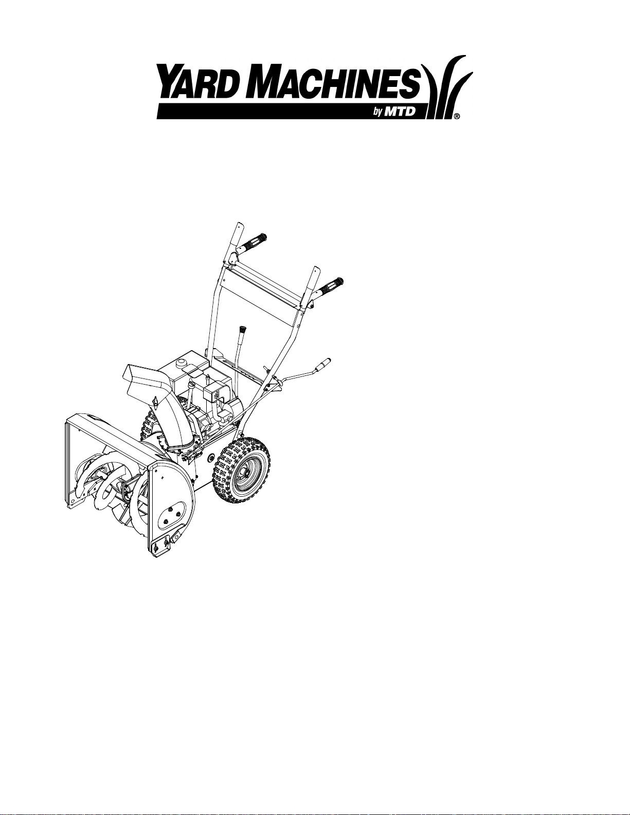
Operator’s Manual
Snow Thrower
Model 611
IMPORTANT: Read safety rules and instructions carefully before operating equipment.
Warning: This unit is equipped with an internal combustion engine and should not be used on or near any unimproved forest-
covered, brush-covered or grass-covered land unless the engine’s exhaust system is equipped with a spark arrester meeting
applicable local or state laws (if any). If a spark arrester is used, it should be maintained in effective working order by the operator.
In the State of California the above is required by law (Section 4442 of the California Public Resources Code). Other states may have
similar laws. Federal laws apply on federal lands. A spark arrester for the muffler is available through your nearest engine authorized
service dealer or contact the service department, P.O. Box 368022 Cleveland, Ohio 44136-9722.
MTD PRODUCTS INC. P.O. BOX 368022 CLEVELAND, OHIO 44136-9722
PRINTED IN U.S.A.
ECO No.1222
FORM NO.
770-10001B.fm
(6/2000)
Page 2

TABLE OF CONTENTS
Content Page
Important Safe Operation Practices...................................................................3
Hardware Pack..................................................................................................5
Assembling Your Snow Thrower........................................................................6
Know Your Snow Thrower .................................................................................11
Operating Your Snow Thrower...........................................................................12
Making Adjustments ..........................................................................................13
Maintaining Your Snow Thrower........................................................................15
Service...............................................................................................................16
Off-Season Storage...........................................................................................18
Troubleshooting.................................................................................................19
Parts List............................................................................................................20
FINDING MODEL NUMBER
This Operator’s Manual is an important part of your new snow thrower. It will help you assemble, prepare
and maintain the unit for best performance. Please read and understand what it says.
Before you start assembling your new equipment, please locate the model plate on the
equipment and copy the information from it in the space provided below. The information on
the model plate is very important if you need help from our Customer Support Department or
an authorized dealer.
• You can locate the model number by standing behind the unit in the operating position and looking
down at the frame below engine. A sample model plate is explained below. For future reference,
please copy the model number and the serial number of the equipment in the space below.
(Model Number)
CLEVELAND, OHIO 44136
(Serial Number)
MTD PRODUC TS INC
Copy the model number here:
Copy the serial number here:
CALLING CUSTOMER SUPPORT
If you have difficulty assembling this product or have any questions regarding the controls, operation or
maintenance of this unit, please call Customer Support Department.
Call 1- (330) 220-4MTD (4683) or 1- (800)-800-7310 to reach a Customer Support
representative. Please have your unit’s model number and serial number ready when you
call. See previous section to locate this information. You will be asked to enter the serial
number in order to process your call .
For more details about your machine, visit our web site at www.mtdproducts.com
2
Page 3

SECTION 1: IMPORTANT SAFE OPERATION PRACTICES
This symbol points out important safety instructions which, if not followed, could endanger the personal
safety and/or property of yourself and others. Read and follow all instructions in this manual before
attempting to operate this machine. Failure to comply with these instructions may result in personal
injury. When you see this symbol—heed its warning.
WARNING: Engine Exhaust, some of its constituents, and certain vehicle components contain or emit
chemicals known to State of California to cause cancer and birth defects or other reproductive harm.
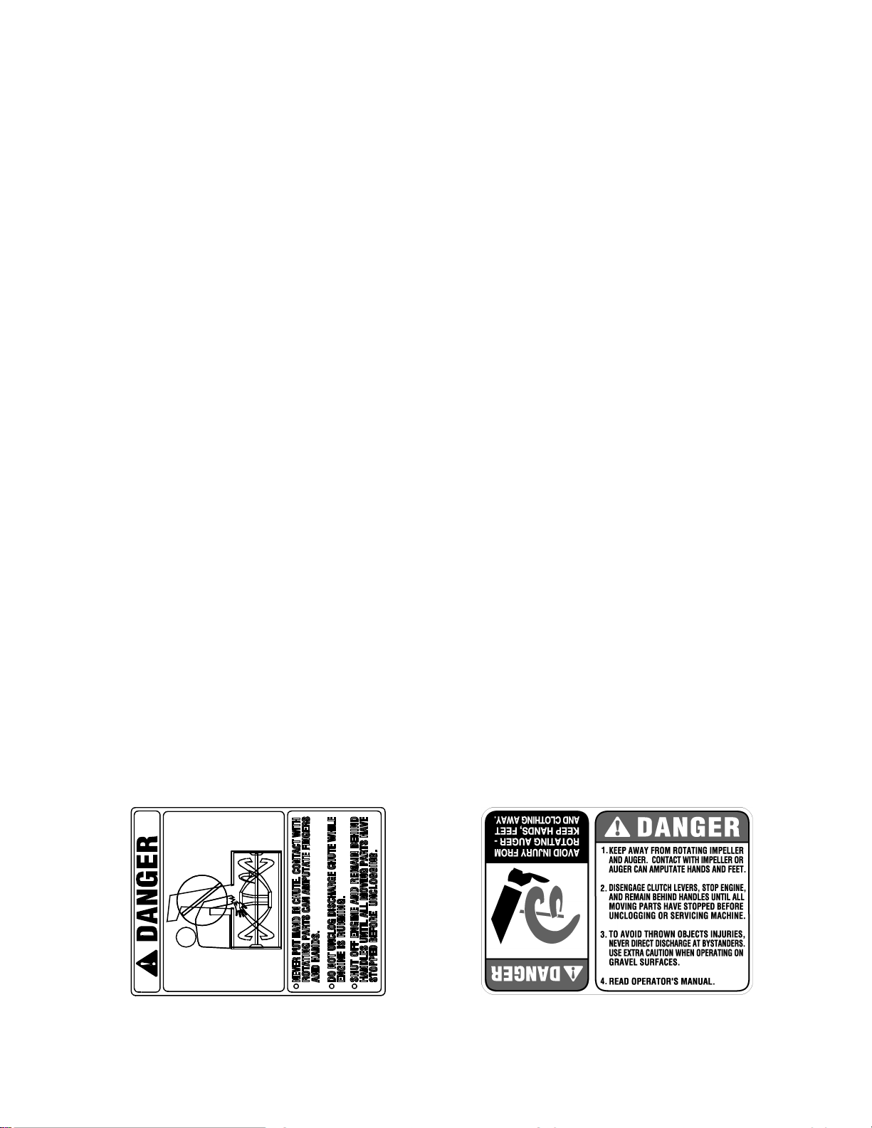
DANGER: This machine was built to be operated according to the rules for safe operation in this
manual. As with any type of power equipment, carelessness or error on the part of the operator can
result in serious injury. This machine is capable of amputating hands and feet and throwing objects.
Failure to observe the following safety instructions could result in serious injury or death.
Training
1. Read, understand, a nd follow all in struction s on the
machine and in the manual(s ) before a ttempting to
assemble and o perate. Keep this ma nual in a safe pl ace
for future and regular re ference a nd for orde ring
replacement parts.
2. Be familiar with all controls and their prope r operation.
Know how to stop the mach ine and d isengage them
quickly.
3. Never allow childre n under 14 y ears old to operate this
machine. Children 14 years old and over should rea d and
understand the op eration in struction s and sa fety rules i n
this manual and should be trained and sup ervised b y a
parent.
4. Never allow adults to operate this machine without
proper instruction.
5. Thrown objects can cause seriou s personal injury . Plan
your snow throwin g pattern to avoid di scharge of mat erial
toward roads, bystanders and the like.
6. Keep bystanders, hel pers, pets and chi ldren at l east 75
feet from the machin e while it is in operatio n. Stop
machine if anyo ne enters the area.
7. Exercise caution to avoid s lipping o r falli ng, espe cially
when operating in reverse.
Preparation
1. Thoroughly inspect the area wh ere the eq uipment i s to
be used. Remove all door mat s, newspa pers, sle ds,
boards, wires and o ther foreig n object s which c ould be
tripped over or throw n by the auger/imp eller.
2. Always wear safet y glasses or eye s hields d uring
operation and while performing an adjustment or repair to
protect your eyes. T hrown ob jects whi ch ricochet can
cause serious inj ury to the eyes.
3. Do not operate wit hout wearing adequate winter outer
garments. Do not wear jewelry, long scarves or other
loose clothing which cou ld becom e entang led in m oving
parts. Wear footwear w hich wi ll improve footing on
slippery surfaces.
4. Use a grounded three wire ex tension cord and receptac le
for all units with electric start engi nes.
5. Adjust collector housing height to clear gravel or crushed
rock surfaces.
6. Disengage all cl utch levers before st arting the engin e.
7. Never attempt to m ake any adjustme nts while engine i s
running, except where spec ifically recomm ended in the
operator’s manual.
8. Let engine and m achine adju st to outd oor tem perature
before starting to clear snow.
9. To avoid personal injury or pro perty damage use extre me
care in handling gasolin e. Gasol ine is e xtremely
flammable and the v apors are explosiv e. Serious
personal injury c an occur w hen gas oline is spilled o n
yourself or your c lothes which c an ignit e. Wash y our skin
and change clot hes immedi ately.
a. Use only an approved gasoline container.
b. Extinguish all cigarettes, cig ars, pipes and other
sources of ignition.
c. Never fuel machine indoo rs.
d. Never remove gas cap or add fue l whil e the
engine is hot or running.
e. Allow engine to cool at leas t two minu tes before
refueling.
f. Never over fill fuel tank. Fil l tank to no more tha n
½ inch below bottom of fill er neck to provide space
for fuel expansi on.
g. Replace gasoli ne cap an d tighten secu rely.
h. If gasoline is sp illed, wip e it off th e engine and
equipment. Move machine to another area . Wait 5
minutes before start ing the e ngine.
i. Never store the machine or fuel containe r inside
where there is an o pen flam e, spark or pilot l ight
(e.g. furnace, water heater, space heate r, clothes
dryer etc.).
j. Allow machine to cool at least 5 mi nutes bef ore
storing.
Operation
1. Do not put hands o r feet near rotating p arts, in the a uger/
impeller housing o r disc harge chu te. Cont act wit h the
rotating parts can am putate ha nds and feet.
2. The auger/impelle r clutch lev er is a safety de vice. Nev er
bypass its operati on. Doing so, makes the ma chine
unsafe and may cause p ersonal i njury.
3. The clutch leve rs must o perate easily in both d irections
and automatical ly return to the disengaged pos ition when
released.
4. Never operate with a miss ing or da maged di scharge
3
Page 4
chute. Keep all safe ty devic es in pl ace and working.
5. Never run an engine indoors or in a poorly vent ilated
area. Engine exhaust contains carbon monoxide , an
odorless and dea dly gas .
6. Do not operate mac hine while under the influenc e of
alcohol or drugs.
7. Muffler and engine beco me hot and can cause a burn. Do
not touch.
8. Exercise extreme ca ution when operating on or cro ssing
gravel surfaces. Stay alert for hidden hazards or traffic.
9. Exercise caution w hen changi ng directi on and w hile
operating on slop es.
10. Plan your snow t hrowing pat tern to av oid disc harge
towards windows, wa lls, cars e tc. To avoid prope rty
damage or personal injury caus ed by a ricochet.
11. Never direct disc harge at c hildren, b ystander s and pet s
or allow anyone in front of t he machi ne.
12. Do not overload machine capa city by attemptin g to clear
snow at too fast of a rate.
13. Never operate this machine without good vi sibility or
light. Always be s ure of yo ur footing and keep a firm hold
on the handles. W alk, never r un.
14. Disengage power to t he aug er/impeller w hen
transporting or not in use.
15. Never operate mach ine at hi gh transp ort speeds on
slippery surfaces. Look down and b ehind an d use ca re
when in reverse.
16. If the machine sh ould start to vi brate abnormally , stop the
engine, disconnect the spark plug an d grou nd it agai nst
the engine. Inspect thoroughly for dam age. Repair any
damage before starting and ope rating.
17. Disengage all cl utch lev ers and st op engin e before y ou
leave the operating position (be hind the handles). Wai t
until the auger/im peller come s to a complete stop befo re
unclogging the d ischarge chute, m aking an y
adjustments, or inspecti ons.
18. Never put your hand in the d ischarge or colle ctor
openings. Always use a cl earing to ol to unc log the
discharge opening.
19. Use only attach ments a nd acce ssories approved by the
manufacturer (e.g. wheel weigh ts, tire c hains, cabs etc.) .
20. If situations occur which are not covered in this manua l,
use care and good judgment. Cont act your dealer or
telephone 1-800-800-73 10 for assistance and the name
of your nearest s ervicing dealer.
Maintenance And Storage
1. Never tamper with sa fety devic es. Check their prop er
operation regularly.
2. Disengage all cl utch lev ers and stop engine. Wait u ntil
the auger/impelle r come to a complet e stop . Disconn ect
the spark plug wir e and ground aga inst the engine to
prevent unintended s tarting before cleaning, r epairing, or
inspecting.
3. Check bolts, and sc rews for pro per tightn ess at fre quent
intervals to keep the machine in sa fe working conditio n.
Also, visually inspect mach ine for an y damage .
4. Do not change the engine governo r setting or over-speed
the engine. The go vernor co ntrols th e maxim um safe
operating speed o f the engi ne.
5. Snow thrower shave plate s and skid shoe s are subjec t to
wear and damage. F or your sa fety prote ction, fre quently
check all compon ents a nd replace with orig inal
equipment manuf acturer’s (O.E.M. ) parts on ly. “Us e of
parts which do not meet the original equipment
specifications ma y lead t o imprope r performan ce and
compromise safety!”
6. Check clutch controls periodically to verify they engage
and disengage proper ly and adjust, if necessary. Re fer to
the adjustment sec tion in th is opera tor’s manual for
instructions.
7. Maintain or replace safety and instruction labels, as
necessary.
8. Observe proper disp osal laws and regu lations for gas,
oil, etc. to protect t he enviro nment.
9. Prior to storing, run machine a few minutes to clear snow
from machine an d prevent freeze up of auger/i mpeller.
10. Never store the machine or fuel cont ainer inside whe re
there is an open flame, s park or pilot light such as a water
heater, furnace ,cloth es dryer etc.
11. Always refer to the o perator’s manual f or prope r
instructions on off-sea son storage.
Your Responsibility:
Restrict the use o f this po wer machine to person s who read ,
understand and fo llow the w arnings an d instruc tions in this
manual and on t he machi ne. The s afety lab els are g iven
below for your r eference.
4
Page 5
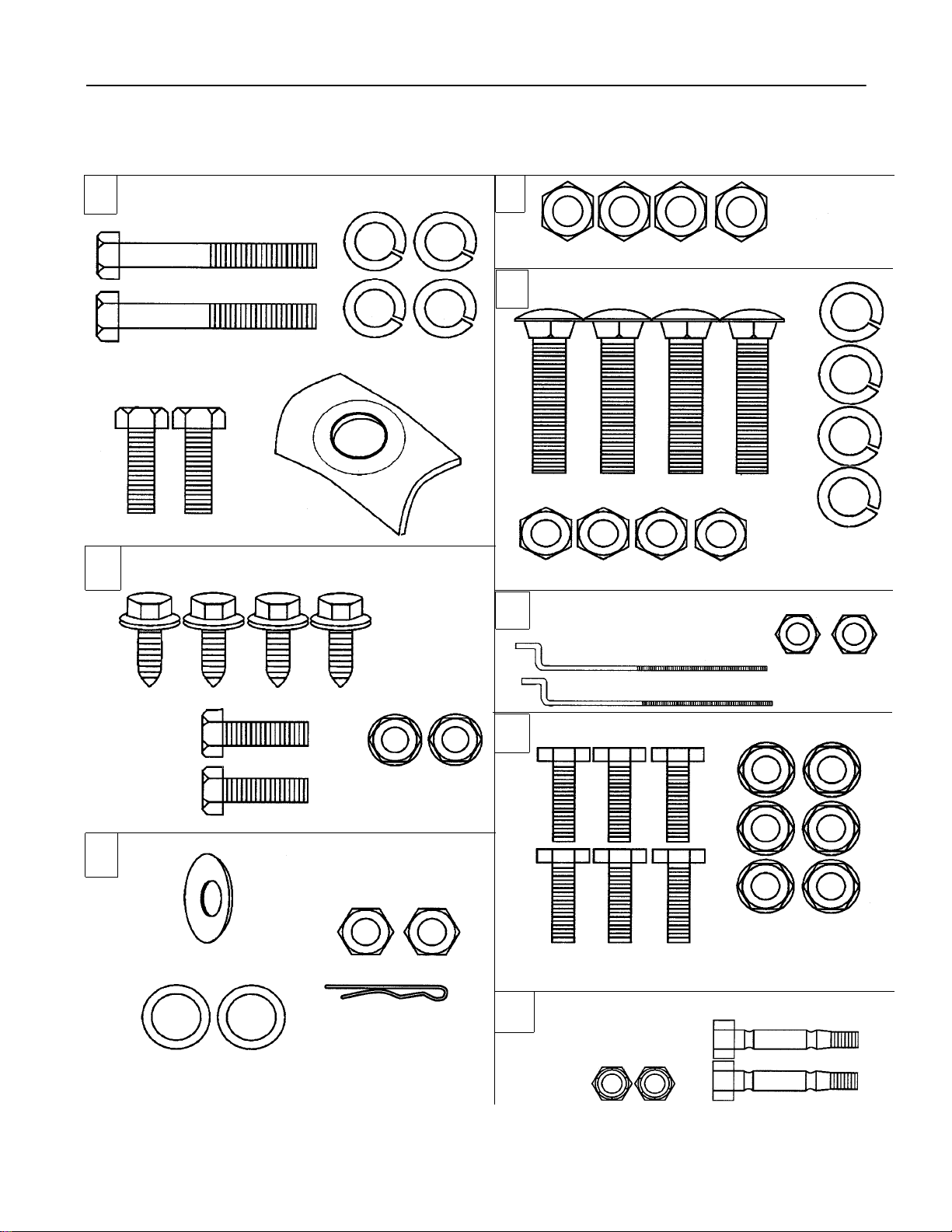
SECTION 2: CONTENTS OF HARDWARE PACK
Lay out the hardware according to the illustration below for identification purposes. Part numbers are shown in
parentheses. (Hardware pack may contain extra items which are not used on your unit.)
A
(2) Hex Bolts (B)
710-3008
D
(2)Hex Bolts (A)
(710-3180)
(4)Lock Washers (C)
(736-0119)
(2) Saddle (I)
(784-5599)
(4) Self-Tapping
Screws (F)
(710-0599)
B
C
E
(4) Carriage Bolts (E)
(710-0262)
(4) Hex Nuts (D)
(712-3010)
(2) “Z” Fitting (R)
(746-0778)
(4) Hex Nuts (D)
(712-3010)
(4) Lock
Washers (C)
(736-0119)
(2) Hex Nuts (J)
(712-0121)
(2) Hex
Bolts (G)
(710-3015)
G
Cupped Washer (N)
(736-0242)
(2) Flat Washers (S)
(736-0185)
* The augers are secured to the spiral shaft with two shear bolts and hex lock nuts. If you hit a hard foreign object or an ice jam, the snow
thrower is designed so that the bolts may shear. Two replacement shear bolts and nuts are provided for your convenience. Store in a safe
place until needed.
(2) Hex Lock Nuts (H)
(712-3027)
(2) Hex Nuts (D)
(712-3010)
Hairpin Clip (T)
(714-0104)
F
(6) Hex Lock Nuts (M)
(712-3027)
(6) Hex Bolts (K)
(710-3015)
*
H
5
(2) Hex Lock Nuts
(712-0429)
(3) Chute Flange Keepers
(Not Shown) (731-0851)
(2) Shear Bolts
(710-0890A)
Page 6
SECTION 3: ASSEMBLING YOUR SNOW THROWER
IMPORT ANT :
gasoline, and check oil level as instructed in the
separate engine manual packed with your unit.
NOTE: References to right or left side of the snow
thrower are determined from behind the unit in the
operating position.
After assembly, service engine with
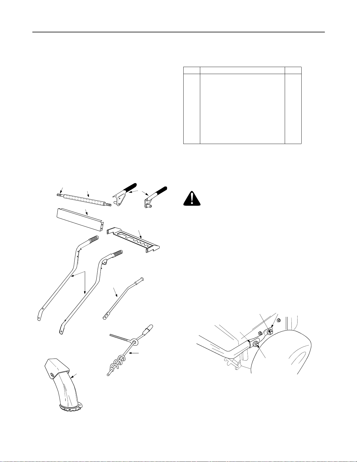
Unpacking
• Remove staples or break glue on top flaps of the
carton. Remove any loose parts included with unit
(i.e., operator’s manual, etc.).
• Cut corners of the carton and lay ends down flat.
Remove packing material.
• Roll unit out of carton. Check carton thoroughly for
loose parts before discarding.
Loose Parts In Carton
B
C
E
A
G
D
F
• Compare Figure 1 with the list below to identify
loose parts in the carton.
Ref. Description Qty.
A Handles (Right and Left) 2
BPivot Rod 1
C Cover Tube 1
D Clutch Grips (Right and Left) 2
E Handle Panel 1
F Speed Selector Plate 1
G Shift Lever 1
H Chute Directional Control Assembly 1
J Chute Assembly 1
I Hardware Pack 1
Tools Required
1. Two adjustable wrenches
Before Assembly
WARNING: Disconnect the spark plug wire
and ground it against the engine to prevent
unintended starting.
Attaching Handles
(Use Hardware Group A.)
• Place right handle in position against the snow
thrower so that the flat side of the handle is against
the frame. Align the bottom hole on the handle to
the corresponding hole on the snow thrower
housing.
• Insert hex bolt (B) and lock washer (C) through
these holes to secure the handle to the snow
thrower housing. See Figure 2. There are weld nuts
welded to the inside of the frame for these bolts. Do
not tighten now.
Hex Bolt B
Lock W asher C
J
Figure 1
Saddle
Washer I
H
Hex Bolt A,
Lock W asher C
Figure 2
• Attach the left handle in the same manner. Do not
tighten no w.
• Place saddle washer (I) over upper holes on
handles as shown in Figure 2. Secure to the frame
with lock washers (C) and hex bolts (A). Do not
tighten no w.
6
Page 7
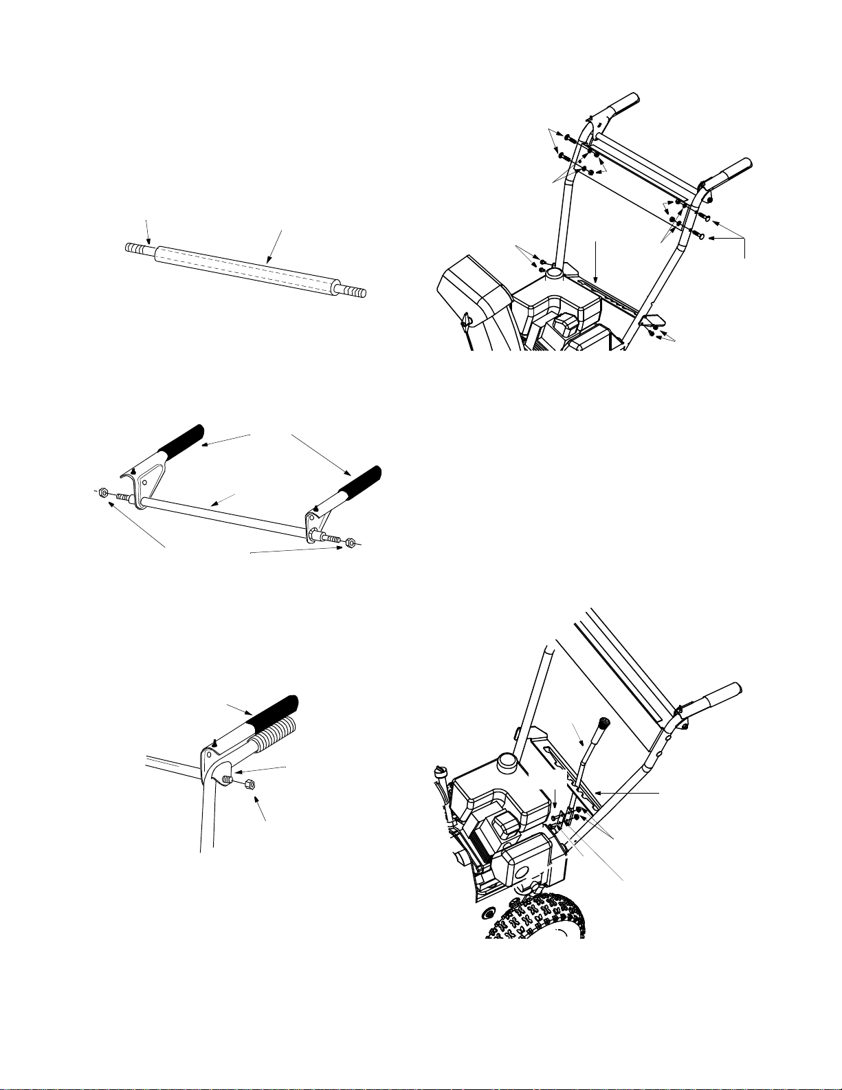
Attaching Clutch Grips
(Use Hardware Group B.)
• Slide the pivot rod into the cover tube as shown in
Figure 3.
NOTE: In some models, the pivot rod and co ver tube
may be pre-assembled.
Pivot Rod
Cover Tube
Carriage
Bolts E
Lock
Washe r C
Self-Tapping
Screws F
H
e
x
Speed
Selector
Plate
Washer C
N
u
t
s
Lock
D
Carriage
Bolts E
Figure 3
• Place the clutch grips in position on the rod as
shown in Figure 4. Thread hex nuts (D) onto each
end of the rod. Tighten nuts allowing the clutch
grips to move freely on the pivot rod. See Figure 4.
Clutch
Grips
Pivot Rod
with Cover
Hex Nuts D
Figure 4
• Insert clutch grip and rod assembly into handle
tabs. Clutch grips must sit on top of the handles.
Thread hex nuts (D) on each end to hold into
position. Do not tighten. See Figure 5.
Clutch Grip and
Rod Assembly
Self-Tapping
Screws F
Figure 6
Attaching Speed Selector Plate
(Use Hardware D.)
• Assemble the speed selector plate to the outside
of the handles as shown in Figure 6. Secure using
two self-tapping screws (F) on each side.
Attaching Shift Lever
• Insert the shift lever through slot in the speed
selector plate. See Figure 7.
NOTE: The bend in the lever should be towards the
operator.
Shift
Lever
Handle
Tab
Hex Nut D
Figure 5
Attaching Handle Panel
(Use Hardware C.)
• Position the handle panel between handles. Insert
two carriage bolts (E) on each side and secure with
lock washers (C) and hex nuts (D). See Figure 6.
Hex
Bolt G
Hex
Bolt G
Hex Lock Nuts H
Shift Lever
Spring
Speed Selector
Plate
Figure 7
• Secure shift lever to the shift lever spring using two
hex bolts (G) and hex lock nuts (H). Tighten both
7
Page 8
bolts finger tight. At this point the shift lever and
shift lever spring are not against each other. As you
tighten the bolts and nuts with two wrenches, these
will pull together. See Figure 7.
• Tighten al l hardware assemble d to this poi nt. Make
sure that clut ch grips are moving free ly.
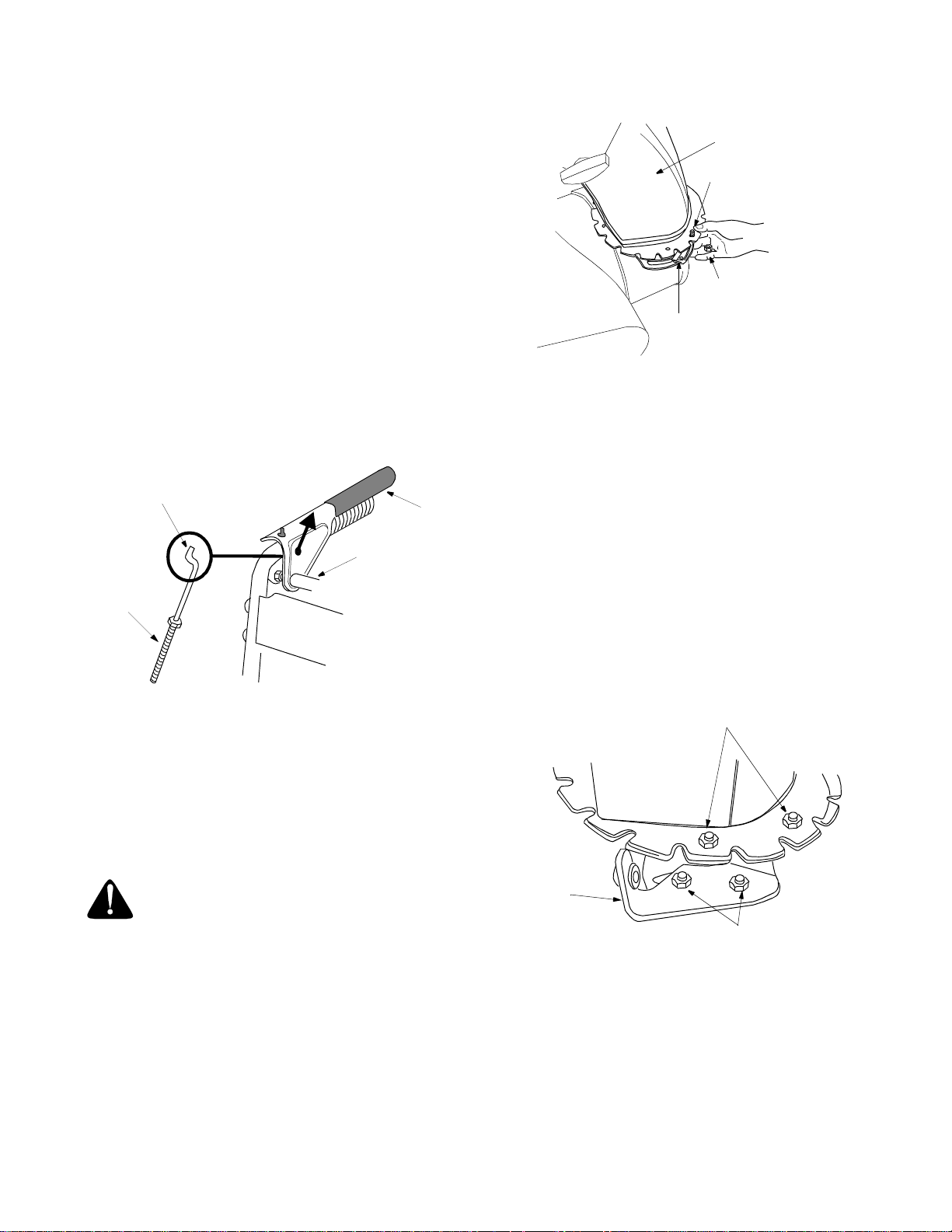
Attaching Control Cables
(Use Hardware E.)
• Thread hex nuts (J) onto the “Z” fittings (R). Insert
“Z” fitting into hole in clutch grips. See Figure 8.
• Route the left cable between engine and speed
selector plate and then between handle panel and
clutch lever pivot rod before threading onto the left
“Z” fitting.
• Assemble the right cable in the same manner.
• Both cables should have minimal slack, but not
tight. Tighten or loosen hex nuts on the “Z” fitting to
adjust.
“Z” Fitting R
Clutch
Grip
Pivot
Rod
Hex Nut J
Handle
Panel
Chute
Assembly
Hex Bolt K
Hex Lock Nut M
Chute Flange
Keeper
Figure 9
• Insert hex bolt (K) up through chute flange keeper
and chute assembly as shown in Figure 9. Secure
with hex lock nut (M). After assembling all three
chute flange keepers, tighten all nuts and bolts
securely. Do not over-tighten.
NOTE: Lock nuts cannot be threaded onto a bolt by
hand. Tighten with two 7/16” or adjustable wrenches.
Attaching Chute Directional Contr ol
(Use Hardware Group G.)
• Loosen the two hex nuts which secure the lower
chute directional control support bracket (see
Figure 10) to the snow thrower housing.
Figure 8
IMPORT ANT :
If the right hand lock-out cable is not
adjusted correctly, wheels will tend to turn. If the left
hand lock-out cable is not adjusted correctly, the
augers will keep on rotating.
IMPORT ANT :
Please note that the drive clutch cable on
units with 16” wheels is routed under the axle. In other
units, the cable is routed over the axle.
WARNING: Do not over-tighten the clu tch
cables. Tension on either cable in the
disengaged (up) position may override the
safety features of the machine.
Attaching Chute Assembly
(Use Hardware Group F.)
• Place chute assembly over chute opening, with the
opening in the chute assembly facing the front of
the unit.
• Place chute flange keepers beneath lip of chute
assembly, with the flat side of chute flange keeper
facing downward. See Figure 9.
Hex Bolts K
Hex Lock Nuts M
Lower
Chute
Directional
Control
Bracket
Hex Nuts
Figure 10
• Place one flat washer (T) over the end of the chute
directional control, then insert the end of the chute
directional control into the hole in the plastic
bushing on the chute bracket. See Figure 11. Place
second flat washer (T) on chute directional control,
and secure with ha irpin clip (S).
8
Page 9
Flat
Washe rs T
Hairpin Clip S
Chute Directional Control
Bracket
Chute
Directional
Control
Figure 11
• Thread on e hex nut (D ) ont o th e eyeb olt on th e
chute direct ional cont rol assem bly until there is at
least two inches of threads showing between the
nut and the eyebolt head. See Figure 12 inset.
• Place the eyebolt into the hole located half way up
the left handle. See Figure 12. Secure with cupped
washer (N) and hex nut (D) making sure that the
cupped side of the washer is against the handle.
2” of thread
Cupped
Washer N
Spiral should engage
teeth of chute here
Figure 13
• Check to make sure all nuts and bolts on the control
panel and all four bolts which secure the handles to
the frame are tight.
Final Assembly & Adjustments
Auger Control
• To check the adjustment of the auger control, push
forward on the left hand clutch grip (depress the
rubber bumper). There should be slack in the cable.
Release the clutch grip. The cable should be
straight. Make certain you can depress the auger
control grip against the left handle completely.
• If necessary, loosen the hex lock nut and thread the
cable in (for less slack) or out (for more slack) as
necessary. Refer to Figure 14.
• Tighten the lock nut against the cable when correct
adjustment is reached.
Hex Nut D
Eye Bolt
Hex Nut D
Chute
Directional
Control
Figure 12
• Adjust the chute directional control bracket so that
the spiral on the chute directional control fully
engages the teeth on the chute assembly. See
Figure 14. Tighten all hardware.
“Z” Fitting
Hex Bolt
Cable
Figure 14
9
Page 10

Traction Control & Shift Lever
• To check the adjustment of the traction control and
shift lever, move the shift lever all the way to the
right to fifth (5) position. With the traction control
released, push the snow thrower forward. The unit
should move forward freely. Then engage the
traction control grip. The wheels should stop
turning.
• Now release the traction control grip, and push the
unit again. Move the shift lever back to the fast
reverse position, then all the way forward again.
There should be no resistance in the shift lever, and
the wheels should keep turning.
• If you feel resistance when moving the shift lever or
the wheels stop when they should not, loosen the
jam nut on the traction control cable and unthread
the cable one turn.
• If the wheels do not stop when you engage the
traction control grip, loosen the jam nut on the
traction control cable and thread the cable in one
turn.
• Recheck the adjustment and repeat as necessary.
Tighten the jam nut to secure the cable when
correct adjustment is reached.
NOTE: If you are not sure that you have adjusted
correctly, refer to the Adjustment section later in this
manual.
Skid Shoes
The space between the shave plate and the ground can
be adjusted.
a. For close sn ow remo val o n a sm ooth
surface, raise skid shoes higher on the auger
housing. See Figure 15.
b. Use a middle or lower position when the area
to be cleared is uneven. See Figure 15.
.
Skid
Shoe
Hex
Carriage
Nuts
Bolts
Low Position
High Position
Figure 15
• Adjust skid shoes by loosening the four hex nuts
and carriage bolts as shown in Figure 15. Move
skid shoes to desired position.
• Make certain the entire bottom surface of skid shoe
is against the ground to avoid uneven wear on the
skid shoes. Retighten nuts and bolts securely.
Tire Pressure (Pneumatic Tires)
The tires are overinflated for shipping purposes.
• Check tire pressure. Maintain pressure between 15
to 20 psi. Refer to tire sidewalls for recommended
tire pressure.
NOTE: If the tire pressure is not equal in both tires, the
unit may pull to one side or the other.
WARNING: Maximum tire pressure under
any circumstance is 30 psi. Equal tire pressure
should be main tained at all times. Exc essive
pressure (over 30 psi) when seating beads
may cause tire/rim assembly to burst with
force sufficient to cause serious injury.
10
Page 11

SECTION 4: KNOW YOUR SNOW THROWER
WARNING: Be famili ar with all the cont rols and their proper operat ion. Know how to sto p the machine
and disengage them quickly.
Shift Lever
T ra ction Control
Discharge Chute
Auger
Oil Fill
Gas Fill
Figure 16
Choke
Ignition
Key
Auger Control
Chute Directional Control
Primer
Throttle
Control
Rope
Start
Handle
Shift Lever
The shift lever is located below the handle panel. See
Figure 16. The shift lever may be moved into one of
seven positions. Run engine with throttle in the fast
position. Use the shift lever to determine ground speed.
There are five forward and two reverse speeds on this
snow thrower. Among the forward speeds, position one
(1) is the slowest and position five (5) is the fastest.
Among reverse speeds, R2 is the faster.
Auger Control
The auger control is located on the left handle.
Squeeze the auger control grip to engage the augers.
Release to stop the augers. See Figure 16.
Traction Control
The traction control is located on the right handle.
Squeeze the traction control grip to engage the wheel
drive. Release to stop. See Figure 16.
Throttle Control
The throttle control is located on the engine. It regulates
the speed of the engine. See Figure 16.
Chute Directional Control
The chute directional control is located on left side of
the snow thrower. See Figure 16. To change the
direction in which snow is thrown, turn chute directional
control as foll ows:
• Crank clockwise to discharge to the left.
• Crank counterclockwise to discharge to the right.
Safety Ignition Key
The ignition key must be inserted in the switch before
the unit will start. Remove the ignition key when snow
thrower is not in use. Do not turn ignition key. See
Figure 16.
Fuel Cut-off Valve (If equipped)
The fuel cut-off valve,if equipped, located under the fuel
tank, controls fuel flow from tank.
11
Page 12

SECTION 5: OPERATING YOUR SNOW THROWER
Before Starting
WARNING: Read, understand, and follow
all instructions and warnings on the machine
and in this manual before operating.
• Check the oil level in the engine before operating;
fill up if necessary. Be careful not to overfill.
• The spark plug wire was disconnected for safety.
Attach spark plug wire to spark plug before starting.
Gas & Oil Fill-Up
• Check oil level and add oil if necessary. Service the
engine with gasoline as instructed in the separate
engine manual packed with your snow thrower.
WARNING: Use extreme care when
handling gasoline. Gasoline is extremely
flammable and the vapors are explosive.
Never fuel the machine indoors or while the
engine is hot or running. Extinguish cigarettes,
cigars, pipes and other sources of ignition.
To Start Engine
• Attach spark plug wire to spark plug. Make certain
the metal loop on the end of the spark plug wire
(inside the boot) is fastened securely over the metal
tip on the spark plug. See Figure 17.
Metal Loop
on Spark
Plug Wire
Rubber Boot
Figure 17
• Make certain the fuel cut-off valve, if your snow
thrower is so equipped, is in OPEN position.
• Make certain the auger and drive clutch levers are
in the disengaged (released) position.
• Move throttle control up to FAST position. Insert
ignition key into slot. Make sure it snaps into place.
Do not turn key
NOTE: Engine will not start unless ignition key is
inserted i nto ig nitio n slot in carb uretor cover .
.
Electric Starter (If equipped)
WARNING: The optional el ectric starter is
equipped with a grounded three-wire power
cord and plug, and is designe d to operate on
120 volt AC household current. It must be
used with a properly grounded three-prong
receptacle at all t imes to a void the poss ibility
of electric shock. Follow all instructions
carefully prior to operating the electric starter.
• Determine that your house wiring is a three-wire
grounded system. Ask a licensed electrician if you
are not certain.
• If your house wiring system is not a thre e-wire
grounded system, do not use this electric starter
under any condi tions.
• If your home electrical system is grounded, but
a three-hole receptacle is not available, one should
be installed by a licensed electrician before using
the electr ic start er.
• If you have a grounded three-prong r eceptacle,
proceed as follows.
• Rotate choke knob to OFF position.
• Connect power cord to switch box on engine. Plug
the other end of power cord into a three-prong 120volt, grounded, AC receptacle.
• Push starter button to crank engine. As you crank
the engine, move choke knob to FULL choke
position.
• When engine starts, release starter button, and
move choke gradually to OFF. If engine falters,
move choke immediately to FULL and then
gradually to OFF.
• When disconnecting the power cord, always unplug
from the three-prong receptacle first, and then from
the snow thrower.
Recoil Starter
• Rotate choke knob to FULL choke position (cold
engine star t).
• If engine is warm, place choke in OFF position
instead of FULL.
• Push primer button two or three times for cold
engine star t.
• If engine is warm, push primer button only once.
NOTE: Always cover ve nt hole in primer button when
pushing. Additional priming may be n ecessary for fir st
start if temperature is below 15 degrees Fahrenheit.
• Grasp starter handle and pull rope out slowly, until
it pulls slightly harder. Let rope rewind slowly.
• Pull starter handle rapidly. Do not allow handle to
snap back. Allow it to rewind slowly while keeping a
firm hold on the starter handle.
12
Page 13

• As engine warms up and begins to operate evenly,
rotate choke knob slowly to OFF position. If engine
falters, return to FULL choke, then slowly move to
OFF position.
To Stop Engine
• Run engine for a few minutes before stopping to
help dry off any moisture on the engine.
• To help prevent possible freeze-up of starter,
proceed as follows.
Electric Starter (If equipped)
• Connect power cord to switch box on engine, then
to 120 volt AC receptacle. With the engine running,
push starter button and spin the starter for several
seconds. The unusual sound made by spinning the
starter will not harm engine or starter. Disconnect
the power cord from receptacle first, and then from
switch box.
Recoil Starter
• With engine running, pull starter rope with a rapid,
continuous full arm stroke three or four times.
Pulling the starter rope will produce a loud clattering
sound, which is not harmful to engine or starter.
• To stop engine, move throttle control to “stop” or
“off” position.
• Remove the ig nition key. Do n ot tu rn key.
Disconnect the spark plug wire from the spark plug
to prevent accidental starting while equipment is
unattended.
NOTE: Do not lose ignition key. Keep it in a safe place.
Engine will not start without the ignition key.
• Wipe all snow and moisture from the carburetor
cover in the area of the control levers. Also, move
control levers back and forth several times.
To Engage Driv e
• With the engine running near top speed, move shift
lever into one of the five FORWARD positions or
two REVERSE positions. Select a speed
appropriate for the snow conditions that exist. Use
the slower speeds until you are familiar with the
operation of t he snow thro wer.
• Squeeze the auger control grip and the augers will
turn. Release it and the augers will stop.
• Squeeze traction control grip and the snow thrower
will move. Release it and drive motion will stop.
• NEVER move shift lever without releasing drive
clutch
To Engage Auger s
• To engage the augers and start throwing snow,
squeeze the auger control grip against the left
handle. Release to stop the augers.
Tire Chains (If equipped)
• Tire chains should be used whenever extra traction
is needed.
Operating Tips
• Allow the engine to warm up for a few minutes as
the engine will not develop full power until it
reaches operating temperature.
WARNING: Muffler, engine and surrounding
areas become hot and ca n cause a burn. Do
not touch.
• For most efficien t snow r emoval, re move sno w
immediately after it falls.
• Discharge snow downwind whenever possible.
Slightly overlap each previous swath.
• Set the skid shoes 1/4" below the scraper bar for
normal usage. The skid shoes may be adjusted
upward for hard-packed snow. Adjust downward
when using on gravel or crushed rock.
• Be certain to follow the precautions listed under ‘‘To
Stop Engine’’ to prevent possible freeze-up.
• Clean the snow thrower thoroughly after each use.
SECTION 6: MAKING ADJUSTMENTS
WARNING: Never attempt to make any
adjustments while the engine is running,
except where specified in operator’s manual.
Chute Assembly
• The distance snow is thrown can be controlled by
adjusting the angle of the top section of the chute
assembly.
Skid Shoe
• The space between the shave plate and the ground
can be adjusted. Refer to the Final Assembly and
Adjustments section on page 10.
Traction Control
• Drain gasoline and engine oil from the snow
thrower. Pl ace plast ic film und er the gas ca p if the
13
Page 14

snow thrower has already been operated. Tip the
snow thrower so that it rests on the auger housing.
See Figure 18.
• Remove the frame cover underneath the snow
thrower by removing si x self-ta pping screws. F or
location of the frame cover, see Figure 18.
Frame Cover
• Loosen the lock nut on the traction control cable
and thread the cable in or out as necessary.
Tighten the lock nut to secure the cable when
correct adjustment is reached. Reassemble the
frame cover.
NOTE: If you placed pla stic under the gas cap earlier,
remove it now.
Auger Control
• To adjust the auger clutch, refer to Final Assembly
and Adjustments on page 9.
Carburetor
WARNING: If any adjustments need to be
made to the engine while the engine is
running (e.g. carburetor), keep clear of all
moving parts. Be careful of muffler, engine
and other surrounding heated surfaces.
• Minor carburetor adjustment may be required to
compensate for differences in fuel, temperature,
altitude and load.
• Refer to the separate engine manual, packed with
your unit, for carburetor adjustment information.
Auger Housing
Figure 18
• When the traction control is released, there must be
clearance between the friction wheel and the drive
plate in all positions of the shift lever. When the
traction control is engaged, the friction wheel must
contact the drive plate. See Figure 19.
Friction
Wheel
Gear Shaft
Drive
Plate
Gap
Figure 19
• If any one of th ese are not occurin g, adjus tment is
necessary. Follow the steps below to adjust the
traction control.
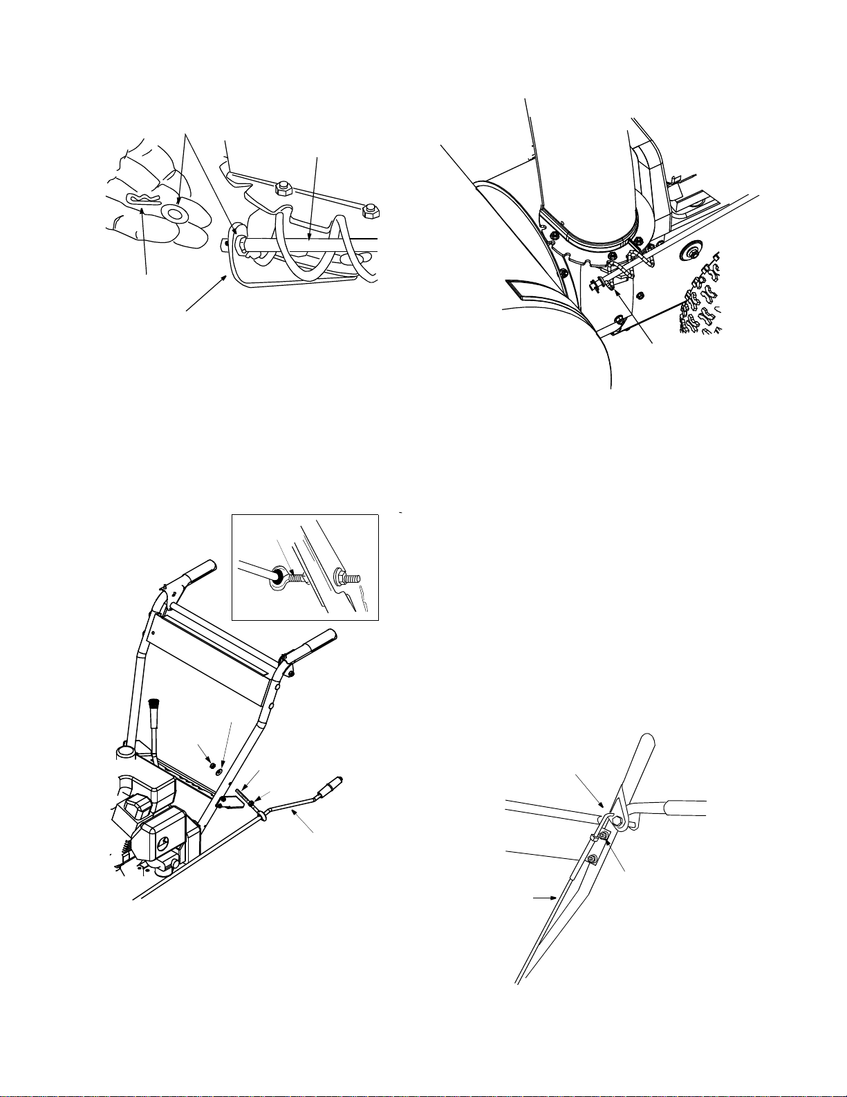
Drive Wheels
• The wheels may be adjusted for two different
methods of operation. Follow the steps below for
adjustment. See Figure 20.
Klick Pin in Hub
Hole
and Inner
Figure 20
One Wheel Driving
• On the right side of the unit, place klick pin in the
outside ax le hole on ly. Do not place pin t hrough
wheel hub. This position gives power drive to the
left wheel only, making the unit easier to maneuver.
Both Wheels Driving
• Rotate wheel assembly to align hole in the hub with
the inner hole on the axle shaft. Insert klick pin in
the hole. Oute r axle sha ft hole shou ld be visi ble.
See Figure 20.
Axle
Hole
Outside
Hole in A x le
14
Page 15

SECTION 7: MAINTAINING YOUR SNOW THROWER
Lubrication
WARNING: Before lubricating, repairing, or
inspecting, disengage all clutch levers and
stop engine. Wait until all moving parts have
come to a complete stop. Disconnect spark
plug wire and groun d it against the engine to
prevent unintended starting.
Engine
• Refer to engine manual for lubrication instructions.
IMPORT ANT :
avoid dripping oil onto transmission parts.
Wheels
• Oil or spray lubricant into bearings at wheels at
least once a season. Pull klick pin, remove wheels,
clean and coat axles with a multipurpose
automotive grease. See Figure 21.
Klick Pin
When lubricating engine or draining oil,
Oil bearings
or spray lubricant
Gear Shaft
• Lubricate the gear shaft with a good all-weather
multi-purpose light grease at least once a season or
after every 25 hours of operation.
IMPORT ANT :
wheel and drive plate.
Keep all grease and oil off the friction
Drive and Shifting Mechanism
• Remove rear cover. Oil any chains, sprockets,
gears, bearings, shafts, and shifting mechanism at
least once a season. Use engine oil or a spray
lubricant. Avoid getting oil on rubber friction wheel
and aluminum drive plate. See Figure 23.
Lube
Shift
Lube chain
Lever
Axle
Figure 21
Chute Directional Control
• The worm gear on the chute control should be
lubricated with multipurpose automotive grease.
Auger Shaft
• At least once a se ason, rem ove shear bolts on
auger shaft. Oil or spray lubricant inside shaft and
lubricate the auger bearings. See Figure 22.
Shear Bolts
Bearings
Figure 22
Avoid oil on
friction wheel
Lube
Gear
Shaft
Figure 23
and drive plate
Gear Case
• The worm gear case has been filled with grease at
the factory. If disassembled for any reason,
lubricate with 2 ounces of shell grease, part number
737-0168.
IMPORT ANT :
the seals could result. Be sure the vent plug is free of
grease in order to relieve pressure.
Do not overfill the gear case. Damage to
Friction Wheel
• The rubber on the friction wheel is subject to wear
and should be checked after 25 hours of operation,
and periodically thereafter. Replace the friction
wheel rubber if any signs of wear or cracking are
found following instructions on page 17.
Tire Pressure
• Follow instructions on page 10.
15
Page 16

SECTION 8: SERVICE
WARNING: Before servicing, repairing, or
inspecting, disengage all clutch levers and
stop engine. Wait until all moving parts have
come to a complete stop. Disconnect spark
plug wire and groun d it against the engine to
prevent unintended starting.
Engine
• Refer to the engine manual for all engine
maintenance procedures.
Augers
• The augers are secured to the spiral shaft with two
shear bolts and hex lock nuts. See Figure 22. If you
hit a hard foreign object or ice jam, the snow
thrower is designed so that the bolts may shear.
• If the augers will not turn, check to see if the bolts
have sheared. Replacement shear bolts and hex
lock nuts have been provided with the snow
thrower. When replacing bolts, spray an oil
lubricant into shaft before inserting new bolts.
Shave Plate and Skid Shoes
• The shave plate and skid shoes on the bottom of
the snow thrower are subject to wear. They should
be checked periodically and replaced when
necessary.
• To remove skid shoes, remove the four carriage
bolts, cupped washers and hex nuts which attach
them to the snow thrower. Reassemble new skid
shoes with the four carriage bolts, cupped washers
(cupped side goes against skid shoes) and hex
nuts. See Figure 24.
• To remove shave plate, remove the carriage bolts,
cupped washers and hex nuts which attach it to the
snow thrower housing. See Figure 24. Reassemble
new shave plate, making sure heads of carriage
bolts are to the inside of housing. Tighten securely.
Belt Removal and Replacement
WARNING: Disconnect spark plug wire
and ground it against the engine to prevent
unintended starting. Drain fuel into an
approved container or place a piece of plastic
film underneath the gas cap to prevent
gasoline from leaking.
Auger Belts
• Remove plastic belt cover from front of the engine
by removing the two self-tapping screws. See
Figure 25.
Belt
Cover
Figure 25
• Drain gasoline from the snow thrower, or place a
piece of plastic under the gas cap.Tip the unit up
and forward so that it rests on auger housing.
• Remove six self-tapping screws from the frame
cover underneath the snow thrower.
• Roll auger belt off the engine pulley. See Figure 26.
Auger
Belt
Self-Tapping
Screws
Drive
Belt
Drive
Pulley
Skid
Shoe
Carriage
Bolts
Shave Plate
Skid
Shoe
Figure 24
Hex Nuts
Idler
Pulley
Engine
Pulley
Idler
Pulley
Figure 26
16
Page 17

• Unhook the idler spring from the hex bolt on the
auger housing. See Figure 27.
• Unhook the support bracket spring from the frame.
NOTE: It may be necessa ry to loosen the s ix nuts that
connect the frame to the auger housing to aid in bel t
removal.
• Lift the rear auger belt from the auger pulley, and
slip belt between the support bracket and the auger
pulley. See Figure 26. Repeat this step to remove
the front auger belt.
• Reassemble both auger drive belts by following
instructions in reverse order.
Friction Wheel
Assembly
Frame
Auger
Housing
Gear
Shaft
Support
Bracket
Spring
Support
Bracket
Auger
Belt
Auger
Pulley
Pin
Idler
Spring
Figure 27
• Slip belt between friction wheel and friction wheel
disc. See Figure 28. Remove and replace belt.
Reassemble in reverse order.
NOTE: The suppo rt bracket must rest on the stop bolt
after the new belt has been assembled. See Figure 28.
Friction Wheel Rubber
Replace the friction wheel rubber if any signs of wear or
cracking are found. Follow instructions below to replace
the rubber .
WARNING: Disconnect the spark plug wire
and ground it against the engine to prevent
unintended starting. Drain fuel into an
approved container or place a piece of plastic
film underneath the gas cap to prevent
gasoline from leaking.
• Tip the snow thrower up and forward, so that it rests
on housing. See Figure 18.
• Remove six self-tapping screws from the frame
cover underneath the snow thrower.
• Remove the klick pins which secure the wheels,
and remove the wheels from the axle.
• Using a wrench to hold the shaft, loosen, but do not
completely remove, the hex nut and bell washer on
the left end of gear shaft. See Figure 29.
• Lightly tap the hex nut to dislodge the ball bearing
from the right side of the frame. Remove the hex
nut and bell washer from the left end of the shaft.
Drive Belt
• Follow first four step s of previo us instruc tions.
• Pull idler pulley up, and lift belt off engine pulley and
friction wheel disc. See Figure 26.
• Using a wrench, loosen the nut on the stop bolt until
the support bracket rests on the auger pulley. See
Figure 28.
Friction
Wheel
Disc
Stop
Bolt
Figure 28
Friction Wheel
Drive Belt
Support Bracket
Hex Nut
Bell Washer
Figure 29
• Slide the gear shaft to the right, then slide the
friction wheel assembly from the shaft.
17
Page 18

• Remove the six screws from the friction wheel
assembly (three from each side). See Figure 30.
Screws
Friction Wheel Rubber
Hub
Screws
Friction Wheel
Plates
Figure 30
SECTION 9: OFF-SEASON STORAGE
• Remove the friction wheel rubber from between the
friction wheel plate.
• Reassemble new friction wheel rubber to the
friction wheel assembly, tightening the six screws in
rotation and with equal force. See Figure 30.
• Slide friction wheel assembly back onto the gear
shaft. Be sure to align the pin on the shift rod with
hole in the friction wheel assembly. See Figure 27.
• Reassemble gear shaft and the wheels. Reattach
the frame cover. Flip snow thrower back to its
operating position and remove any plastic from
under the machine or around the gas cap if you had
put it earlier.
WARNING: Never store the machine or
fuel container indoors where th er e is an open
flame, spark or p ilot light such as on a water
heater, furnace, clothes dryer or other gas
appliances.
If unit is to be stored over 30 days, prepare for storage
as follows:
• Remove gasoline from carburetor and fuel tank to
prevent gum deposits from forming on these parts
and causing possible malfunction of engine.
• Run engine until fuel tank is empty and engine
stops due to lack of fuel.
• Drain carburetor by pressing upward on bowl drain,
located below the carburetor cover.
WARNING: Drain fuel into an approved
container outdoors, away from open flame.
Allow engine to cool. Extinguish cigarettes,
cigars, pipes, and other sources of ignition
prior to draining fuel. Fuel left in engine for
extended period deteriorates and will cause
serious starting problems.
NOTE: Fuel stabilizer is an acceptable alternative in
minimizing the formation of fuel gum deposits during
storage. Add stabilizer to gasoline in fuel tank or
storage container. Always follow mix ratio found on
stabilizer container. Run engine at least 10 minutes
after adding stabilizer to allow it to reach carburetor. Do
not drain carburetor if using fuel stabilizer.
• Remove all dirt from exterior of engine and
equipment.
• Remove spark plug and pour one ounce of engine
oil through spark plug hole into cylinder. Cover
spark plug hole with rag. Crank engine several
times to distribute oil. Replace spark plug.
• Follow lubrication recommendations on page 15.
NOTE: When storing any type of power equipment in
an unventilated or metal sto rage shed, care shou ld be
taken to rust proof the equipment. Using a ligh t oil or
silicone, coat the equipment, especially any chains,
springs, bearings and cables.
18
Page 19

SECTION 10: TROUBLE SHOOTING GUIDE
T rouble Possible Cause(s) Corrective Action
Engine fails to star t Fuel tank empty, or stale fuel.
Blocked fuel line.
Choke not in ON position
Faulty spark plug.
Key not in switch on e ngine.
Spark plug wire discon nected.
Primer button not depressed.
Fuel shut-off valve closed
(if so equipped).
Engine runs erratic Unit running on CHOKE.
Blocked fuel line or stale fuel.
Water or dirt in fuel system .
Carburetor out of adjustment.
Loss of power Spark plug wire loos e.
Gas cap vent ho le plugge d.
Exhaust port plugged.
Engine overheats Carburetor not adjusted
properly.
Incorrect fuel mixture.
Excessive vibration Loose parts or damaged
auger.
Unit fails to propel
itself
Unit fails to
discharge snow
Incorrect adjustment of drive
cable.
Drive belt loose or damag ed.
Discharge chute c logged.
Foreign object lod ged in
auger.
Incorrect adjustment of drive
cable.
Drive belt loose or damag ed.
Fill tank with clean, fresh gas oline. F uel will n ot last o ver thirty
days unless a fuel stabiliz er is used.
Clean fuel line.
Move switch to ON po sition
Clean, adjust gap o r repla ce.
Insert key.
Connect spark plug wire .
Refer to the engine m anual.
Open fuel shut-off valve.
Move choke lever to OFF pos ition.
Clean fuel line; fill tank with cle an fresh g asoline. Fuel w ill not la st
over thirty days unless a fuel stabilizer is used.
Drain fuel tank. Refill with fresh fuel.
Refer to the engine m anual.
Connect and tighten spark pl ug wire.
Remove ice and snow from cap. Be certain vent hole is clear.
Clean following th e engine manual.
Refer to the engin e manual pa cked w ith your unit or ha ve
carburetor adjusted by an au thorized service dealer.
Drain fuel tank. Re fill with proper fuel mixture.
Stop engine immediat ely and disconne ct spark plug w ire. Tighte n
all bolts and nuts. Make all necess ary repai rs. If vib ration
continues, have unit service d by an authorized serv ice dealer.
Adjust drive cable . Refer t o page 1 0 of this manual.
Replace drive belt. Refer to pa ge 17 of this man ual.
Stop engine immediat ely and disconne ct sp ark plug w ire. Cle an
discharge chute and inside o f auger ho using.
Stop engine immedia tely and disconnect sp ark plug wire. Remove
object from auger.
Adjust drive cable . Refer t o page 10 of this manual.
Replace drive belt. Refer to pa ge 17 of this man ual.
NOTE: For repairs beyond the minor adjustments above, contact your local authorized service dealer.
19
Page 20

SECTION 11: PARTS LIST FOR MODEL 611
12
1
9
5
13
8
16
10
15
14
4
3
7
11
2
Ref.
No.
10 721-0327 Seal-Oil
11 736-0351 Washer-Flat
12 736-0369 Washer-Flat
13 736-0445 Washer-Flat
14 737-0168 Grease
15 741-0662 Bearing-Flange
16 741-0663 Bearing-Flange
17 618-0152 Ass’y. Complete 22"
6
17
Part
No. Description
1 618-0123 Housing—R.H.
618-0124 Housing—L.H.
2 710-0642 Hex Screw 1/4-20 x .75
3 711-1020 Spiral Axle 22”
711-0908 Spiral Axle 24”
4 714-0161 Key
5 715-0143 Pin-Spiral
6 717-0526 Shaft-Worm
7 717-0528 Gear-Worm
8 718-0186 Collar-Thrust
9 721-0325 Plug
618-0120 Ass’y Complete 24”
5
2
Size Ref. No. 1 Ref. No. 2 Ref. No. 3 Ref. No. 4 Ref. No. 5 Ref. No 6
13 x 4 634-0114 734-1732 734-0255 734-1713 741-0401 714- 0143
13 x 5( w/22” Housin g) 634-0166 734-1527 734-0255 684-0129 741-04 01 714-0143
13 x 5( w/24” Housin g) 734-1714 734-1527 734-0255 734-1713 741-0401 714- 0143
1
4
3
Wheel Ass’y
Complete
5
Wheel Assembly
Tire Only Air Valve Rim Only Sleeve
20
Klik Pin
Bearing (2)
Page 21

Snow Thrower Model 611
IMPORTANT: For a proper working machine,
use Factory Approved Parts.
V-BELTS are specially designed to engage
and disengage safely. A substitute (non OEM)
V-Belt can be dangerous by not disengaging
completely.
11
12
27
22
13
15
16
20
16
10
1
2
3
4
8
9
4
5
7
6
23
24
25
Ref.
No.
Part
No. Description
1 710-1652 Hex Washer Screw 1/4-20 x.625
2 731-1324 Belt Cover
3 732-0339 Extension Spring
4 710-0627 Hex Screw 5/16-24 x .75
5 710-3005 Hex Cap Screw 3/8-16 x 1.25
6 05896A Drive Clutch Bracket
7 748-0234 Shoulder Spacer
8 756-0985 Pulley Half
9 754-0343 V-Belt
10 756-0984 Pulley Half
11 736-0270 Bell Washer
12 710-0230 Hex Cap Screw 1/4-28 x .50
13 756-0313 Flat Idler
14 710-1245 Lock Cap Screw 5/16-24
14
17
18
21
19
Ref.
No.
Part
No. Description
26
15 712-0181 Lock Jam Nut 3/8-16
16 756-0569 Pulley Half
17 736-0242 Bell Washer
18 736-0505 Flat Washer
19 736-0507 Washer
20 754-0430A Belt
21 756-0967 Auger Pulley
22 736-0247 Flat Washer
23 736-0331 Bell Washer
24 710-0696 Hex Cap Screw 3/8-24
25 748-0360 Pulley
26 710-0654A Hex Washer Screw 3/8-16 x 1.0
27 629-0071 Extension Cord
OEM-390-986 Electric Start Kit
21
Page 22

Snow Thrower Model 611
18
32
31
38
30
35
15
28
29
34
27
14
13
12
11
10
1
2
3
4
9
16
Hook must be away
from back of housing
17
22
21
23
26
25
20
18
5
6
7
8
19
9
24
37
39
40
42
36
41
40
39
33
44
45
43
18
23
22
16
22
Page 23

Snow Thrower Model 611
Ref.
No.
1 712-0116 Lock Jam Nut 3/8-24
2 756-0178 Flat Idler
3 784-5632A Auger Idler Arm
4 710-0459A Hex Cap Screw 3/8-24 x 1.50
5 738-0281 Shoulder Screw
6 736-0167 Wave Washer
7 732-0611 Extension Spring
8 712-3068 Hex Nut 5/16-18
9 712-3010 Hex Nut 5/16-18
10 736-0119 Lock Washer 5/16
11 05931A Housing
12 741-0309 Ball Bearing
13 710-0451 Carriage Bolt 5/16-18
14 705-5226 Reinforcement Chute
15 684-0052B 22” Housing Assembly
16 712-3010 Hex Nut 5/16-18
17 736-0119 Lock Washer 5/16
18 736-0242 Bell Washer
19 741-0475 Bushing
20 784-5647 Chute Directional Control Bracket
21 731-1379B Chute Adapter
22 712-0324 Hex Lock Nut 1/4-20
23 736-0463 Flat Washer
24 710-0451 Carriage Bolt
25 710-0703 Carriage Screw 1/4-20 x .75
Part
No. Description
684-0039C 24” Housing Assembly
Ref.
No.
26 710-0604 Hex Washer Screw 5/16-18
27 736-0169 Lock Washer 3/8
28 712-0798 Hex Nut 3/8-16
29 710-0451 Carriage Bolt 5/16-18 x .75
30 784-5580 Snow Shoe
31 736-0242 Bell Washer
32 712-3010 Hex Nut 5/16-18
33 784-5576 22” Shave Plate
34 710-0451 Carriage Bolt 5/16-18 x .62
35 684-0065 Impeller Assembly
36 715-0114 Pin
37 618-0152 22” Gear Assembly
38 605-5252A Spiral 22” RH
39 736-0188 Flat Washer
40 741-0493A Flange Bushing
41 605-5253A Spiral 22” LH
42 710-0890A Shear Bolt 5/16-18 x 1.5
43 712-0429 Lock Nut 5/16-18
44 741-0245 Hex Flange Bearing
45 784-5618 Bearing Housing
46 737-0318 Grease Fitting
Part
No. Description
784-5581A 24” Shav e Plate
618-0120 24” Gear Assembly
605-5188A Spiral 24” RH
605-5189A Spiral 24” LH
23
Page 24

Snow Thrower Model 611
35
34
33
34
36
16
37
14
15
13
1
7
18
19
3
17
20
2
4
5
11
5
7
6
12
5
8
2
9
5
10
24
38
20
41
39
40
20
42
43
22
21
30
23
25
27
28
29
30
31
32
24
Page 25

Snow Thrower Model 611
Ref.
No.
1 705-5234 Clutch Lever Assembly - RH
2 720-0204 Grip
3 731-1500 Piv ot Rod Cover
4 747-0905 Piv ot Rod
5 712-3010 Hex Nut 5/16-18
6 736-0119 Lock Washer 5/16
7 735-0199A Rubber Bumper
8 705-5233 Clutch Lever Assembly - LH
9 712-3027 Lock Hex Nut 1/4-20
10 710-0262 Carriage Bolt 5/16-18 x 1.50
11 746-0778 Z - Cable
12 684-0047A Handle - LH
13 705-5232 Panel
14 684-0048A Handle - RH
15 705-5231 Speed Select Panel
16 710-0599 Hex Washer Screw 1/4-20 x .50
17 720-0223 Grip
18 747-0904 Shift Lever
19 710-3015 Hex Cap Screw 1/4-20 x .75
20 712-3027 Hex Lock Nut 1/4-20
21 732-0733 Shift Lever Spring
22 710-0788 Hex Washer Screw 1/4-20 x 1.0
Part
No. Description
Ref.
No.
23 736-0242 Bell Washer
24 726-0100 Push Cap
25 720-0201A Chute Knob
27 747-0697 Eyebolt
- 735-0234 Grommet only
28 705-5204A Chute Directional Control Assembly
29 784-5599 Handle Tab
30 736-0119 Lock Washer 5/16
31 710-3180 Hex Cap Screw 5/16-18 x 1.75
32 710-3008 Hex Cap Screw 5/16-18 x .75
33 731-0921 Upper Chute
34 736-0159 Washer 5/16
35 720-0284 Knob
36 712-0429 Hex Lock Nut 5/16-18
37 710-0451 Carriage Bolt 5/16-18 x .75
38 710-0276 Carriage Screw 5/16-18 x 1.0
39 731-1300A Lower Chute
40 731-0851A Flange K eep er
41 710-3015 Hex Cap Screw 1/4-20 x .75
42 714-0104 Cotter Pin
43 736-0185 Flat Washer 3/8
Part
No. Description
25
Page 26

Snow Thrower Model 611
38
32
33
20
34
37
37
31
40
8
39
28
20
26
35
27
36
14
13
15
16
25
24
22
41
7
11
10
6
25
29
23
21
26
5
4
17
18
20
1
3
2
8
1
4
41
For 16” wheel axle only
19
41
10
9
4
5
7
1
5
11
12
1
Blower
Housing
30
26
1
1
Page 27

Snow Thrower Model 611
Ref. No. Part No. Description
710-0599 Self-Tapp. Screw 1/4-20 x 0.5”
1.
784-5688 Drive Cable Guide Bracket
2.
784-5687A Auger Clutch Cable Bracket
3.
756-0625 Roller Cable
4.
738-0924 Hex Screw 1/4-28
5.
784-5630A Frame Assembly
6.
741-0563 Ball Bearing
7.
736-0105 Bell Washer
8.
712-0116 Lock Jam Nut
9.
10.
11.
12.
13.
14.
15.
16.
17.
18.
19.
20.
21.
741-0598 Hex Flange Bearing
736-0188 Flat Washer
784-5689A Front Support Guide Bracket
710-0538 Lock Hex Screw
736-0242 Bell Washer .340 ID x .872 OD
714-0474 Cotter Pin
736-0160 Flat Washer .536 ID x .930 OD
710-1107 Hex Washer Screw 1/4-20 x .625”
784-5590 Frame Shift Bracket
784-5638 Frame Cover
710-0599 Hex Washer Screw 1/4-20
736-0351 Flat Washer .760 ID x .50 OD
Ref. No. Part No. Description
22.
23.
24.
25.
26.
27.
28.
29.
30.
31.
32.
33.
34.
35.
36.
37.
38.
39.
40.
41.
717-1445 Gear
714-0126 Key
717-1444 7-Tooth Shaft
715-0249 Roll Pin
714-0143 Klik Pin
684-0042C Friction Wheel Assembly
656-0012A Friction Disc Wheel
684-0013B Wheel Shift Rod Assembly
746-0897 Drive Cable
748-0190 Spacer
684-0021 Friction Wheel Bracket Assembly
732-0264 Extension Spring
712-0711 Jam Nut 3/8-24
746-0898 Drive Cable
738-0869 22 .2” Axle (used w/ 13 x 4 tire)
738-0991 21.4” Axle (used w/ 13 x 5 tire)
784-5617A Friction Plate
735-0243 Friction Wheel Rubber
718-0301A Friction Wheel Hub
618-0063 Friction Wheel Bearing
712-0703 Nut Insert
27
Page 28

MANUFACTURER’S LIMITED WARRANTY FOR:
The limited warranty set forth below is given by MTD
PRODUCTS INC (“MTD”) with respect to new merchandise
purchased and used in the United States, its possessions
and territories.
MTD warrants this product against defects in material and
workmanshi p for a peri od of two ( 2) years comm encin g on
the date of original pu rcha se and will, at its option, repa ir o r
replace, free of charge, any part fou nd to be defective in
material or workmanship. This limited warranty shall only
apply if this product has been operated and maintained in
accordance with the Operator’s Manual furnis hed wit h the
product, and has not been subject to misuse, abuse, commercial use, neglect, accident, improper maintenance,
alteration, vandalism, theft, fire, water or damage because
of other peril or natural d is ast er. Damage resulting from the
installation or use of any accessory or attachment not
approved by MTD Products Inc. for use with the product(s)
covered by this manua l will void your warranty as to any
resulting damages.
Normal wear parts or components thereof are subject to
separate te rms as follows: All n orm al wear par t or comp onent failures will be covered on the product for a period of
90 days regardl ess of cau se. After 90 days, but within th e
two year period, nor mal wear part failures will be covered
ONLY IF caused by defects in material or workmanship of
OTHER component parts. Normal wear parts and components include, but are not limited to, belts, blades, blade
adapters, grass bags, rider deck wheels, seats, snow
thrower skid shoes, shave plates and tires. Batter ies are
covered by a 90-day limited replacement warranty.
HOW T O OBTAIN SERVICE: Warranty service is available,
WITH PROOF OF PURCHASE THROUGH YOUR LOCAL
AUTHORIZED SERVICE DEALER. To locate the dealer in
your area, please check for a listing in the Yellow Pages or
contact the Customer Ser vice Department of MTD PRODUCTS INC by calling 1-800-8 00-7 310 or writing to P.O. Box
368022, Cleveland, Ohio 44136-9722.
This limited warranty does not provide coverage in the
following cases:
a. The engine or component parts thereof. These items
carry a separate manufacturer’s warranty. Please refer
to the applicable manufacturer’s warranty on these
items.
b.Log splitter pumps, valves and cylinders have a sepa-
rate one year warranty.
c. Routine maintenance items such as lubricants, filters,
blade sharpening and tune-ups, or adjustments such
as brake adjustments, clutch adjustments or deck
adjustments; and nor mal deterioration of the exter ior
finish due to use or exposure.
d. MTD does not extend any warranty for products sold
or exported outside of the United States of America,
its possessions and territories, except those sold
through MTD’s authorized channels of export distribu-
tion.
No implied warranty, including any implied warranty of
merchantability or fitness for a particular purpose,
applies after the applicable period of express written
warranty above as to the parts as identified. No other
express warranty or guaranty, whether written or oral,
except as mentioned above, given by any person or
entity, including a dealer or retailer, with respec t to any
product shall bind MTD. During the period of the Warranty, the exclusive remedy is repair or replacement of
the product as set forth above. (Some states do not
allow limitations on how long an implied warranty lasts, so
the above limitation may not apply to you.)
The provisio ns as se t forth in this Warranty pro v ide the
sole and exclusive remedy arising from the sales. MTD
shall not be liable for incidental or consequential loss
or damages including, without limitation, expenses
incurred for substitute or replacement lawn care services, for t ran s po rtation o r fo r re l at ed exp e n se s, or for
rental expenses to temporarily replace a warranted
product. (Some states do not allow the exclusion or limita-
tion of incidental or consequential damages, so the above
exclusion or limitation may not apply to you.)
In no event shall recovery of any kind be greater than the
amount of the purchase price of th e produ ct sold. Al terat ion
of the safety features of the product shall void this Warranty. You assume the risk and liability for loss, damage, or
injury to you and your property and/or to others and their
property arising out of the use or misuse or inability to use
the product.
This limited warranty shall not extend to anyone other than
the original purchaser, original lessee or the person for
whom it was purchased as a gift.
How State Law Relates to this Warranty: This limited
warranty gives you specific legal rights, and you may also
have other rights which vary from state to state.
 Loading...