

Page 1

Safe Operation Practices • Set-Up • Operation • Maintenance • Service • Troubleshooting • Warranty
TO
L
Two-Stage Snow Thrower m 500 & 600 Series
P.O. Box 1386, 97 KENT AVENUE, KITCHENER, ON N2G 4J1
PrintedIn USA 769-06123
09.09.10
Page 2
ToTheOwner
ThankYou
Thank you for purchasing your new equipment. It was carefully
engineered to provide excellent performance when properly
operated and maintained.
Please read this entire manual prior to operating the equipment.
It instructs you how to safely and easily set up, operate and
maintain your machine. Please be sure that you, and any other
persons who will operate the machine, carefully follow the
recommended safety practices at all times. Failure to do so could
result in personal injury or property damage.
All information in this manual is relative to the most recent
product information available at the time of printing. Review
this manual frequently to familiarize yourself with the machine,
its features and operation. Please be aware that this Operator's
Manual may cover a range of product specifications for
various models. Characteristics and features discussed and/or
illustrated in this manual may not be applicable to all models.
Tableof Contents
1
The manufacturer reserves the right to change product
specifications, designs and equipment without notice and
without incurring obligation.
If you have any problems or questions concerning the machine,
phone your local service dealer or contact us directly. Customer
Support telephone numbers, website address and mailing
address can be found on this page. We want to ensure your
complete satisfaction at all times.
Throughout this manual, all references to right and left side of the
machine are observed from the operating position.
The engine manufacturer is responsible for all engine-related
issues with regards to performance, power-rating, specifications,
warranty and service. Please refer to the engine manufacturer's
Owner's/Operator's Manual, packed separately with your
machine, for more information.
Safe Operation Practices ........................................ 3
Assembly & Set-Up .................................................. 7
Con trois ................................................................... 12
Operation ................................................................ 15
Maintenance & Adjustment. ................................. 16
RecordProductinformation
Before setting up and operating your new equipment, please
locate the model plate on the equipment and record the
information in the provided area to the right. You can locate the
model plate by standing at the operator's position and looking
down at the rear of the frame. This information will be necessary,
should you seek technical support via our web site, Customer
Support Department, or with a local authorized service dealer.
Service ..................................................................... 19
Troubleshooting .................................................... 23
Replacement Parts ................................................ 24
Warranty ................................................................ 25
Emission Control Warranty Statement ............... 26
MODEL NUMBER
[3D[3D[3D[3D[3D[3
SERIAL NUMBER
D[3D[3D[3D[3D[3D
CustomerSupport
Please do NOT"return the unit to the retailer from which it was purchased, without first contacting Customer Support.
If you have difficulty assembling this product or have any questions regarding the controls, operation, or maintenance of
this machine, you can seek help from the experts. Choose from the options below:
Visit our web at www.mtdcanada.ca
Locate your nearest dealer from Customer Support: 1-800-668-1238
Contact MTD CANADA • P.O. Box 1386 • 97 Kent Avenue • Kitchener, Ontario, Canada • N2G 4J1
Page 3
ImportantSafeOperationPractices
WARNING! This symbol points out important safety instructions which, if not followed,
could endanger the personal safety and/or property of yourself and others. Read and follow
all instructions in this manual before attempting to operate this machine. Failure to comply
with these instructions may result in personal injury.
When you see this symbol. HEED ITS WARNING!
CALIFORNIA PROPOSITION 65
WARNING! Engine Exhaust, some of its constituents, and certain vehicle components
contain or emit chemicals known to State of California to cause cancer and birth defects
or other reproductive harm.
DANGER: This machine was built to be operated according to the safe operation practices in
this manual. As with any type of power equipment, carelessness or error on the part of the
operator can result in serious injury. This machine is capable of amputating fingers, hands,
toes and feet and throwing foreign objects. Failure to observe the following safety
instructions could result in serious injury or death.
2
Training Preparation
1. Read, understand, and follow all instructions on the
machine and in the manual(s) before attempting to
assemble and operate. Keep this manual in a safe place for
future and regular reference and for ordering replacement
parts.
2. Be familiar with all controls and their proper operation.
Know how to stop the machine and disengage them
quickly.
3. Never allow children under 14 years of age to operate this
machine. Children 14 and over should read and understand
the instructions and safe operation practices in this manual
and on the machine and be trained and supervised by an
adult.
4. Never allow adults to operate this machine without proper
instruction.
5. Thrown objects can cause serious personal injury. Plan
your snow-throwing pattern to avoid discharge of material
toward roads, bystanders and the like.
6. Keep bystanders, pets and children at least 75 feet from the
machine while it is in operation. Stop machine if anyone
enters the area.
Exercise caution to avoid slipping or falling, especially
when operating in reverse.
Thoroughly inspect the area where the equipment is to be used.
Remove all doormats, newspapers, sleds, boards, wires and other
foreign objects, which could be tripped over or thrown by the
auger/impeller.
1. Always wear safety glasses or eye shields during operation
and while performing an adjustment or repair to protect
your eyes. Thrown objects which ricochet can cause serious
injury to the eyes.
2. Do not operate without wearing adequate winter outer
garments. Do not wear jewelry, long scarves or other loose
clothing, which could become entangled in moving parts.
Wear footwear which will improve footing on slippery
surfaces.
3. Use a grounded three-wire extension cord and receptacle
for all machines with electric start engines.
4. Adjust auger housing height to clear gravel or crushed rock
surfaces.
5. Disengage all control levers before starting the engine.
6. Never attempt to make any adjustments while engine is
running, except where specifically recommended in the
operator's manual.
7. Let engine and machine adjust to outdoor temperature
before starting to clear snow.
Page 4
SafeHandling of Gasoline
To avoid personal injury or property damage use extreme care
in handling gasoline. Gasoline is extremely flammable and the
vapors are explosive. Serious personal injury can occur when
gasoline is spilled on yourself or your clothes which can ignite.
Wash your skin and change clothes immediately.
a. Use only an approved gasoline container.
b. Extinguish all cigarettes, cigars, pipes and other
sources of ignition.
Never fuel machine indoors.
C.
d.
Never remove gas cap or add fuel while the engine is
hot or running.
e. Allow engine to cool at least two minutes before
refueling.
f. Never over fill fuel tank. Fill tank to no more than 1/2
inch below bottom of filler neck to provide space for
fuel expansion.
g. Replace gasoline cap and tighten securely.
h. If gasoline is spilled, wipe it off the engine and
equipment. Move machine to another area. Wait 5
minutes before starting the engine.
i. Never store the machine or fuel container inside
where there is an open flame, spark or pilot light
(e.g. furnace, water heater, space heater, clothes
dryer etc.).
j. Allow machine to cool at least 5 minutes before
storing.
k. Never fill containers inside a vehicle or on a truck
or trailer bed with a plastic liner. Always place
containers on the ground away from your vehicle
before filling.
I. If possible, remove gas-powered equipment from
the truck or trailer and refuel it on the ground. If this
is not possible, then refuel such equipment on a
trailer with a portable container, rather than from a
gasoline dispenser nozzle.
m. Keep the nozzle in contact with the rim of the fuel
tank or container opening at all times until fueling is
complete. Do not use a nozzle lock-open device.
Operation
1. Do not put hands or feet near rotating parts, in the auger/
impeller housing or chute assembly. Contact with the
rotating parts can amputate hands and feet.
2. The auger/impeller control lever is a safety device. Never
bypass its operation. Doing so makes the machine unsafe
and may cause personal injury.
3. The control levers must operate easily in both directions
and automatically return to the disengaged position when
released.
4.
Never operate with a missing or damaged chute assembly.
Keep all safety devices in place and working.
5. Never run an engine indoors or in a poorly ventilated area.
Engine exhaust contains carbon monoxide, an odorless
and deadly gas.
6. Do not operate machine while under the influence of
alcohol or drugs.
7. Muffler and engine become hot and can cause a burn. Do
not touch. Keep children away.
8. Exercise extreme caution when operating on or crossing
gravel surfaces. Stay alert for hidden hazards or traffic.
9. Exercise caution when changing direction and while
operating on slopes.
10. Plan your snow-throwing pattern to avoid discharge
towards windows, walls, cars etc. Thus, avoiding possible
property damage or personal injury caused by a ricochet.
11. Never direct discharge at children, bystanders and pets or
allow anyone in front of the machine.
12. Do not overload machine capacity by attempting to clear
snow at too fast of a rate.
13.
Never operate this machine without good visibility or light.
Always be sure of your footing and keep a firm hold on the
handles. Walk, never run.
14.
Disengage power to the auger/impeller when transporting
or not in use.
15.
Never operate machine at high transport speeds on
slippery surfaces. Look down and behind and use care
when backing up.
16. If the machine should start to vibrate abnormally, stop
the engine, disconnect the spark plug wire and ground it
against the engine. Inspect thoroughly for damage. Repair
any damage before starting and operating.
17. Disengage all control levers and stop engine before you
leave the operating position (behind the handles). Wait
until the auger/impeller comes to a complete stop before
unclogging the chute assembly, making any adjustments,
or inspections.
18. Never put your hand in the discharge or collector openings.
Always use the clean-out tool provided to unclog the
discharge opening. Do not unclog chute assembly while
engine is running. Shut off engine and remain behind
handles until all moving parts have stopped before
unclogging.
19. Use only attachments and accessories approved by the
manufacturer (e.g. wheel weights, tire chains, cabs etc.).
20. When starting engine, pull cord slowly until resistance
is felt, then pull rapidly. Rapid retraction of starter cord
(kickback) will pull hand and arm toward engine faster than
you can let go. Broken bones, fractures, bruises or sprains
could result.
21.
If situations occur which are not covered in this manual, use
care and good judgment. Contact Customer Support for
assistance and the name of your nearest servicing dealer.
4 J SECTION 2 -- IMPORTANT SAFE OPERATION PRACTICES
Page 5
Clearinga CloggedDischargeChute
Hand contact with the rotating impeller inside the discharge
chute is the most common cause of injury associated with snow
throwers. Never use your hand to clean out the discharge chute.
To clear the chute:
1. SHUTTHE ENGINE OFF!
2. Wait 10 seconds to be sure the impeller blades have
stopped rotating.
3. Always use a clean-out tool, not your hands.
Maintenance & Storage
1. Never tamper with safety devices. Check their proper
operation regularly. Refer to the maintenance and
adjustment sections of this manual.
2. Before cleaning, repairing, or inspecting machine
disengage all control levers and stop the engine. Wait until
the auger/impeller come to a complete stop. Disconnect
the spark plug wire and ground against the engine to
prevent unintended starting.
3. Check bolts and screws for proper tightness at frequent
intervals to keep the machine in safe working condition.
Also, visually inspect machine for any damage.
4. Do not change the engine governor setting or over-speed
the engine. The governor controls the maximum safe
operating speed of the engine.
5. Snow thrower shave plates and skid shoes are subject to
wear and damage. For your safety protection, frequently
check all components and replace with original equipment
manufacturer's (OEM) parts only. "Use of parts which do
not meet the original equipment specifications may lead to
improper performance and compromise safety!"
6. Check control levers periodically to verify they engage
and disengage properly and adjust, if necessary. Refer
to the adjustment section in this operator's manual for
instructions.
7. Maintain or replace safety and instruction labels, as
necessary.
8. Observe proper disposal laws and regulations for gas, oil,
etc. to protect the environment.
9. Prior to storing, run machine a few minutes to clear snow
from machine and prevent freeze up of auger/impeller.
10. Never store the machine or fuel container inside where
there is an open flame, spark or pilot light such as a water
heater, furnace, clothes dryer etc.
11. Always refer to the operator's manual for proper
instructions on off-season storage.
12. Check fuel line, tank, cap, and fittings frequently for cracks
or leaks. Replace if necessary.
13. Do not crank engine with spark plug removed.
14.
According to the Consumer Products Safety Commission
(CPSC) and the U.S. Environmental Protection Agency (EPA),
this product has an Average Useful Life of seven (7) years,
or 60 hours of operation. At the end of the Average Useful
Life have the machine inspected annually by an authorized
service dealer to ensure that all mechanical and safety
systems are working properly and not worn excessively.
Failure to do so can result in accidents, injuries or death.
Donotmodifyengine
To avoid serious injury or death, do not modify engine in any
way. Tampering with the governor setting can lead to a runaway
engine and cause it to operate at unsafe speeds. Never tamper
with factory setting of engine governor.
NoticeRegardingEmissions
Engines which are certified to comply with California and federal
EPA emission regulations for SORE (Small Off Road Equipment)
are certified to operate on regular unleaded gasoline, and
may include the following emission control systems: Engine
Modification (EM), Oxidizing Catalyst (OC), Secondary Air
Injection (SAI) and Three Way Catalyst (TWC) if so equipped.
SparkArrestor
internal combustion engine and should not be used
i_ll WARNING! This machine is equipped with an
Ira spark arrester is used, it should be maintained in effective
working order by the operator.
A spark attester for the muffler is available through your nearest
engine authorized service dealer.
on or near any unimproved forest-covered, brush
covered or grass-covered land unless the engine's
exhaust system is equipped with a spark arrester
meeting applicable local or state laws (if any).
SECTION 2 -- IMPORTANT SAFE OPERATION PRACTICES S
Page 6
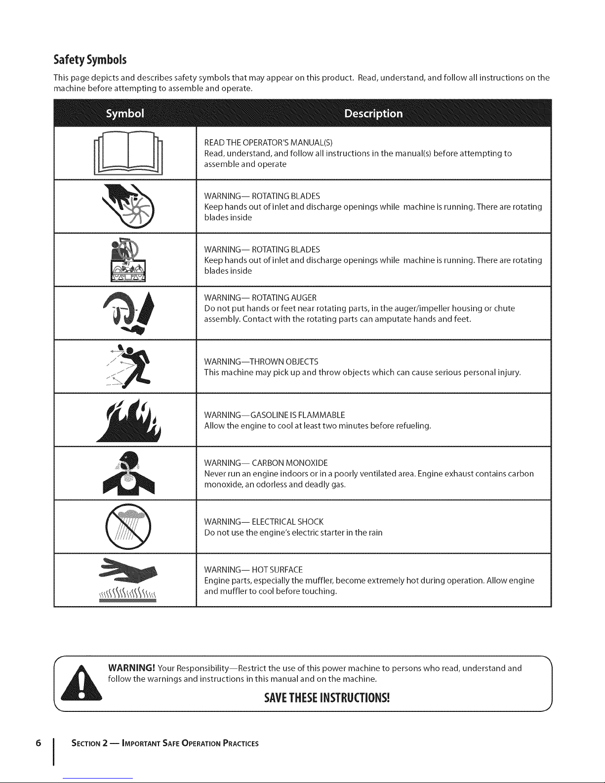
Safety Symbols
This page depicts and describes safety symbols that may appear on this product. Read, understand, and follow all instructions on the
machine before attempting to assemble and operate.
READ THE OPERATOR'S MANUAL(S)
Read, understand, and follow all instructions in the manual(s) before attempting to
assemble and operate
WARNING-- ROTATING BLADES
Keep hands out of inlet and discharge openings while machine is running. There are rotating
blades inside
WARNING-- ROTATING BLADES
Keep hands out of inlet and discharge openings while machine is running. There are rotating
blades inside
WARNING-- ROTATING AUGER
Do not put hands or feet near rotating parts, in the auger/impeller housing or chute
assembly. Contact with the rotating parts can amputate hands and feet.
........!i........
WARNING--THROWN OBJECTS
This machine may pick up and throw objects which can cause serious personal injury.
WARNING--GASOLINE IS FLAMMABLE
Allow the engine to cool at least two minutes before refueling.
WARNING-- CARBON MONOXIDE
Never run an engine indoors or in a poorly ventilated area. Engine exhaust contains carbon
monoxide, an odorless and deadly gas.
WARNING-- ELECTRICAL SHOCK
Do not use the engine's electric starter in the rain
WARNING-- HOT SURFACE
Engine parts, especially the muffler, become extremely hot during operation. Allow engine
and muffler to cool before touching.
WARNING! Your Responsibility--Restrict the use of this power machine to persons who read, understand and
follow the warnings and instructions in this manual and on the machine.
6 I SECTION 2 -- IMPORTANT SAFE OPERATION PRACTICES
SAVETHESEINSTRUCTIONS!
Page 7
Assembly& Set-Up
IMPORTANT:The snow thrower is shipped with oil and WITHOUT GASOLINE. After assembly, refer to separate engine manual for
proper fuel and engine oil recommendations.
NOTE: Remove all loose parts and any packing material before assembling.
NOTE: References to right or left side of the snow thrower are determined from behind the unit in the operating position.
NOTE:This Operator's Manual covers several models, handle
panels, lights and chute cranks are some features that may vary
by model. Not all features referenced (or engines )ictured) in
this manual are applicable to all snow thrower models.
NOTE: Replacement auger shear pins are included with this
manual (or stowed in the plastic handle panel). Refer to Augers in
the Maintainance Section for more information regarding shear
pin replacement.
NOTE: For models with electric start the extension cord is
fastened with a cable tie to the rear of the auger housing for
shipping purposes. Cut the cable tie and remove it before
operating the snow thrower.
HandleAssembly
Place the shift lever in the Forward-6 position.
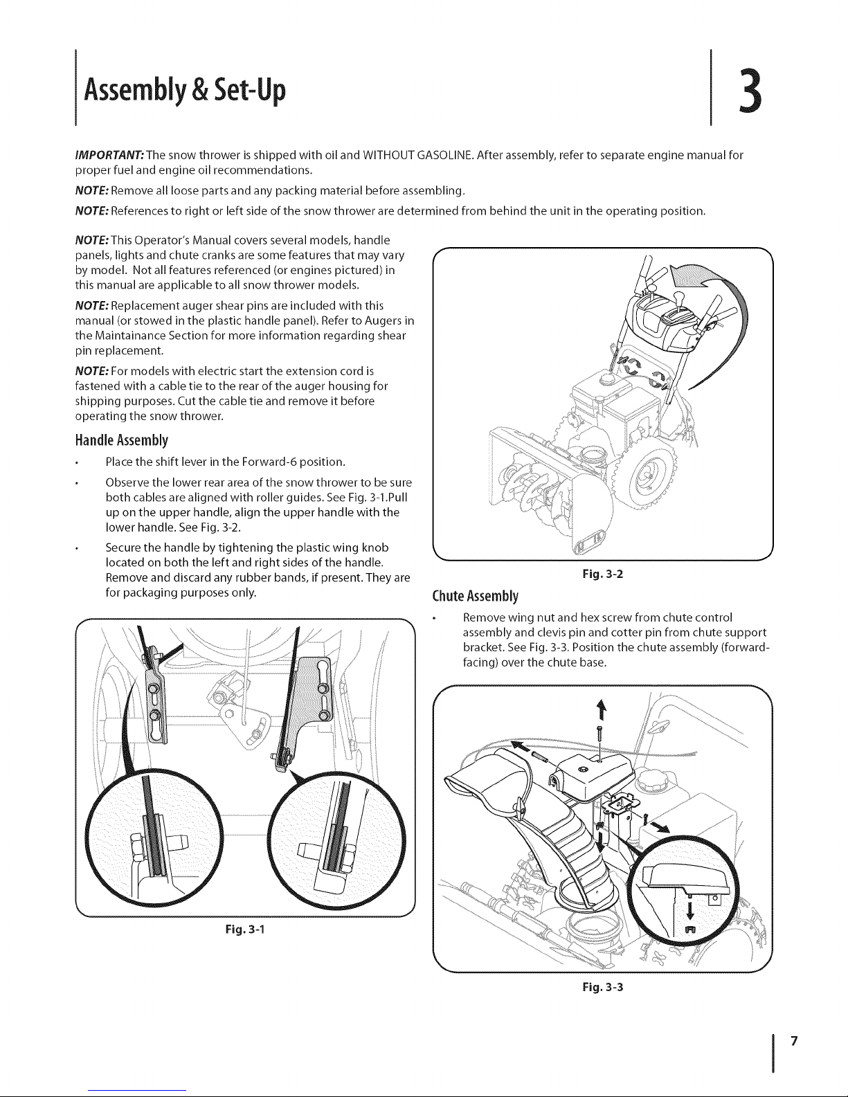
Observe the lower rear area of the snow thrower to be sure
both cables are aligned with roller guides. See Fig. 3-1.Pull
up on the upper handle, align the upper handle with the
lower handle. See Fig. 3-2.
Secure the handle by tightening the plastic wing knob
located on both the left and right sides of the handle.
Remove and discard any rubber bands, if present. They are
for packaging purposes only.
\ \
ChuteAssembly
Remove wing nut and hex screw from chute control
assembly and clevis pin and cotter pin from chute support
bracket. See Fig. 3-3. Position the chute assembly (forward-
facing) over the chute base.
Fig. 3-2
3
!/
Fig. 3-3
Page 8
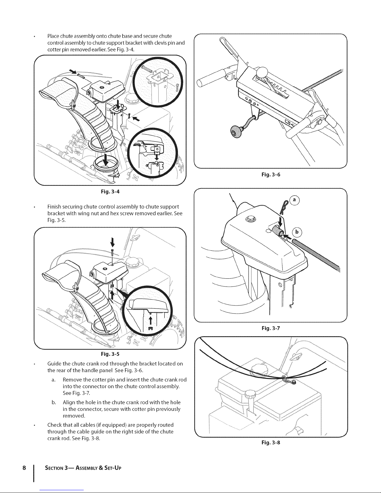
Place chute assembly onto chute base and secure chute
control assembly to chute support bracket with clevis pin and
cotter pin removed earlier. See Fig. 3-4.
Fig. 3-4
Finish securing chute control assembly to chute support
bracket with wing nut and hex screw removed earlier. See
Fig. 3-5.
Fig. 3-6
Fig° 3-5
Guide the chute crank rod through the bracket located on
the rear of the handle panel See Fig. 3-6.
a. Remove the cotter pin and insert the chute crank rod
into the connector on the chute control assembly.
See Fig. 3-7.
b. Align the hole in the chute crank rod with the hole
in the connector, secure with cotter pin previously
removed.
Check that all cables (if equipped) are properly routed
through the cable guide on the right side of the chute
crank rod. See Fig. 3-8.
8 I SECTION3-- ASSEMBLY& SET-UP
J
Fig. 3-7
?
Fig. 3-8
Page 9
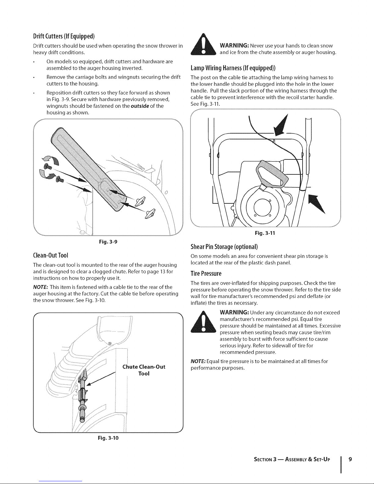
DriftCutters(if Equipped)
Drift cutters should be used when operating the snow thrower in
heavy drift conditions.
On models so equipped, drift cutters and hardware are
assembled to the auger housing inverted.
Remove the carriage bolts and wingnuts securing the drift
cutters to the housing.
Reposition drift cutters so they face forward as shown
in Fig. 3-9. Secure with hardware previously removed,
wingnuts should be fastened on the outside of the
housing as shown.
_ WARNING: Never use your hands to clean snow
and ice from the chute assembly or auger housing.
LampWiringHarness(If equipped))
The post on the cable tie attaching the lamp wiring harness to
the lower handle should be plugged into the hole in the lower
handle. Pull the slack portion of the wiring harness through the
cable tie to prevent interference with the recoil starter handle.
See Fig. 3-11.
Fig. 3-9
Clean-OutTool
The clean-out tool is mounted to the rear of the auger housing
and is designed to clear a clogged chute. Refer to page 13 for
instructions on how to properly use it.
NOTE: This item is fastened with a cable tie to the rear of the
auger housing at the factory. Cut the cable tie before operating
the snow thrower. See Fig. 3-10.
Chute Clean-Out
Tool
Fig. 3-11
ShearPinStorage(optional)
On some models an area for convenient shear pin storage is
located at the rear of the plastic dash panel.
TirePressure
The tires are over-inflated for shipping purposes. Check the tire
pressure before operating the snow thrower. Refer to the tire side
wall for tire manufacturer's recommended psi and deflate (or
inflate) the tires as necessary.
manufacturer's recommended psi. Equal tire
_ ARNING: Under any circumstance do not exceed
NOTE: Equal tire pressure is to be maintained at all times for
performance purposes.
pressure should be maintained at all times. Excessive
pressure when seating beads may cause tire/rim
assembly to burst with force sufficient to cause
serious injury. Refer to sidewall of tire for
recommended pressure.
Fig. 3-10
SECTION 3 -- ASSEMBLY& SET-UP 9
Page 10

Adjustment
ChuteAssembly(optional)
The distance snow is thrown can be adjusted by changing the
angle of the chute assembly. To do so:
I. Stop the engine as instructed in the separate engine
manual and wait until all moving parts have come to a
complete stop.
2. Loosen the plastic wing knob found on the left side of the
chute assembly.
3. Pivot the chute upward or downward before retightening
the wing knob. See Fig, 3-12.
/
/
/
/
/
/
Fig. 3-13
Fig. 3-12
SkidShoes
The snow thrower skid shoes are adjusted upward at the factory
for shipping purposes. Adjust them downward, if desired, prior
to operating the snow thrower.
CAUTION: It is not recommended that you operate this snow
thrower on gravel as it can easily pick up and throw loose gravel,
causing personal injury or damage to the snow thrower and
surrounding property.
For close snow removal on a smooth surface, raise skid
shoes higher on the auger housing.
Use a middle or lower position when the area to be cleared
is uneven, such as a gravel driveway.
NOTE: If you choose to operate the snow thrower on a gravel
surface, keep the skid shoes in position for maximum clearance
between the ground and the shave plate.
To adjust the skid shoes:
1. Loosen the four hex nuts (two on each side) and carriage
bolts. Move skid shoes to desired position. See Fig. 3-13.
2. Make certain the entire bottom surface of skid shoe is
against the ground to avoid uneven wear on the skid shoes.
3. Retighten nuts and bolts securely.
Fig. 3-14
NOTE: Some models are equipped with reversible skid shoes
and may be turned over to increase their lifespan.
SECTION 3-- ASSEMBLY& SET-UP
°1
Page 11

AugerControlTest
WARNING : Prior to operating your snow thrower,
carefully read and follow all instructions below.
Perform all adjustments to verify your unit is
operating safely and properly.
Perform the following test before operating your snow thrower
for the first time and at the start of each winter.
Check the adjustment of the auger control as follows:
1. When the auger control is released and in the disengaged
"up" position, the cable should have very little slack. It
should NOT be tight.
2. In a well-ventilated area, start the snow thrower engine as
instructed in the separate engine manual.
3. While standing in the operator's position (behind the snow
thrower), engage the auger.
4. Allow the auger to remain engaged for approximately ten
(10) seconds before releasing the auger control. Repeat this
several times.
5. With the auger control in the disengaged "up" position,
walk to the front of the machine.
6. Confirm that the auger has completely stopped rotating
and shows NO signs of motion. If the auger shows ANY
signs of rotating, immediately return to the operator's
position and shut off the engine. Wait for ALL moving parts
to stop before re-adjusting the auger control.
7. To readjust the control cable, loosen the upper hex screw
on the auger cable bracket.
8. Position the bracket upward to provide more slack (or
downward to increase cable tension).See Fig. 3-15.
9. Retighten the upper hex screw.
10. Repeat Auger Control Test to verify proper adjustment has
been achieved.
Fig. 3-15
\
\
\,
\
\
J
SECTION3 -- ASSEMBLY& SET-UP 11
Page 12

ControlsandFeatures
f
Headlight (optional)
ChuteAssembly
Clean Out
Tool
DriftCutters
(optional)
DriveControl
Shift
2Way Chute Control (optional)
AugerControl
HeatedGrips (optional)
Control (optional)
ChuteDirectional Control
4
Augers
Snow thrower controls and features are described below and
illustrated in Fig. 4-1.
Shift [ever
The shift lever is located on the handle panel and is used to
determine ground speed and direction of travel.
Forward
There are six forward (F) speeds. Position one (I) is the slowest
and position six (6) is the fastest.
Reverse
There are two reverse (R) speeds. One (I) is the slower and two (2)
is the faster.
SkidShoe
J
Fig. 4-1
SkidShoes
Position the skid shoes based on surface conditions. Adjust
upward for hard-packed snow. Adjust downward when
operating on gravel or crushed rock surfaces.
Augers
When engaged, the augers rotate and draw snow into the auger
housing.
ChuteAssembly
Snow drawn into the auger housing is discharged out the chute
assembly.
Headlight(if soequipped)
The headlight is on whenever the engine is running.
Page 13

Drift Cutters (ifsoequipped)
The drift cutters are designed for use in deep snow. Their use
is optional for normal snow conditions. Maneuver the snow
thrower so that the cutters penetrate a high standing snow drift
to assist snow falling into the augers for throwing.
HeatedGrips(ifsoequipped)
I .eATeD.ANDLeGRIPs
o. Ioff /
This switch is located on the rear of the snow thrower dash panel.
To activate the heated handles, toggle the switch to the "ON"
position to generate heat within the handle grips. Toggle the
switch to the "OFF" position after using the snow thrower.
SteeringTriggerControls (ifsoequipped)
STEERING TRIGGER CONTROLS
J
The left and right wheel steering trigger controls are located on
the underside of the handles.
Squeeze the right control to turn right.
Squeeze the left control to turn left.
until you are familiar with these controls.
1 _ CAUTION: Operate the snow thrower in open areas
ChuteClean-OutTool
The auger control is located on the left handle. Squeeze the
control grip against the handle to engage the augers and start
snow throwing action. Release to stop.
DriveControl/ AugerClutchLock
DRIVE CONTROL
The drive control is located on the right handle. Squeeze the
control grip against the handle to engage the wheel drive.
Release to stop.
The drive control also locks the auger control so that you can
operate the chute directional control without interrupting
the snow throwing process. If the auger control is engaged
simultaneously with the drive control, the operator can release
the auger control (on the left handle) and the augers will remain
engaged. Release both controls to stop the augers and wheel
drive.
NOTE: Always release the drive control before changing speeds.
Failure to do so will result in increased wear on your machine's
drive system.
clogged chute assembly. Shut off engine and remain
_ ARNING! Never use your hands to clear a
The chute clean-out tool is conveniently fastened to the rear of
the auger housing with a mounting clip. Should snowand ice
become lodged in the chute assembly during operation, proceed
as follows to safely clean the chute assembly and chute opening:
1. Release both the Auger Control and the Drive Control.
2.
3.
4.
5. Refasten the clean-out tool to the mounting clip on the
While standing in the operator's position (behind the snow
thrower), engage the auger control for a few seconds to clear any
remaining snow and ice from the chute assembly.
behind handles until all moving parts have stopped
before unclogging.
Stop the engine as instructed in the separate engine
manual.
Remove the clean-out tool from the clip which secures it to
the rear of the auger housing.
Use the shovel-shaped end of the clean-out tool to
dislodge and scoop any snow and ice which has formed in
and near the chute assembly.
rear of the auger housing, reinsert the key and start the
snow thrower's engine.
SECTION4 -- CONTROLS AND FEATURES 13
Page 14

Two-WayChuteControlTM (optional)
This two-way control lever is meant to control the distance of
snow discharge from the chute. Tilt the lever forward or rearward
to adjust the distance snow will be thrown.
ChuteDirectional Control (optional)
The chute directional control can be turned clockwise or
counterclockwise to change the direction in which snow is
thrown.
CHUTE DIRECTIONAL CONTROL
DISCHARGE_ DISCHARGE
%
CHUTETILT
DOWH
J
a
CHUTETILT
UP
J
SECTION 4 -- CONTROLS AND FEATURES
Page 15

Operation
Starting and Stopping the Engine
Refer to the Engine Operator's Manual packed with your snow
thrower for instructions on starting and stopping the engine.
ToEngageDrive
1. With the throttle control in the Fast (rabbit) position, move
shift lever into one of the six forward (F) positions or two
reverse (R) positions. Select a speed appropriate for the
snow conditions and a pace you're comfortable with.
2. Squeeze the drive control against the handle the snow
thrower will move. Release it and drive motion will stop.
ToEngageAugers
1. To engage augers and start snow throwing, squeeze the
left hand auger control against the left handle. Release to
stop augers.
2. While the auger control is engaged, squeeze the drive
control to move, release to stop. Do not shift speeds while
the drive is engaged.
NOTE: The following instructions are for models equipped with
the optional interlock mechanism only.
NOTE:This drive lever also locks auger control so you can turn
the chute control without interrupting the snow throwing
process.
3. Release the auger control; the interlock mechanism should
keep the auger control engaged until the drive control is
released.
4. Release the drive control to stop both the augers and
the wheel drive. To stop the auger, both levers must be
released.
ReplacingShearPins
The augers are secured to the spiral shaft with two shear
pins and cotter pins. If the auger should strike a foreign
object or ice ja m, the snow thrower is designed so that the
pins may shear. If the augers will not turn, check to see if the
pins have sheared. See Fig. 5-1.
with anything other than OEM Part No. 738-
_ AUTION: NEVER replace the auger shear pins
_ ARNING! Always turn off the snow thrower's
04124A replacement shear pins. Any damage to
the auger gearbox or other components as a
result of failing to do so will NOT be covered by
your snow thrower's warranty.
engine and remove the key prior to replacing
shear pins.
Fig. 5=1
15
Page 16

Maintenance&Adjustments
6
Maintenance
Engine
Refer to the Engine Operator's Manual packed with your snow
thrower.
TirePressure
Refer to "Assembly & Set-Up" section of this manual.
ShavePlateand SkidShoes
The shave plate and skid shoes on the bottom of the snow
thrower are subject to wear. They should be checked periodically
and replaced when necessary.
NOTE: Some units are equipped with reversible skid shoes and
may be turned over to increase their lifespan.
To remove skid shoes:
1. Remove the four carriage bolts and hex flange nuts which
secure them to the snow thrower.
2. Reassemble new skid shoes with the four carriage bolts
(two on each side) and hex flange nuts. Refer to Fig. 6-1.
To remove shave plate:
3. Remove the carriage bolts and hex nuts which attach it to
the auger housing.
4. Reassemble new shave plate, making sure heads of carriage
bolts are to the inside of housing. Tighten securely.
Lubrication
GearShaft
The gear (hex) shaft should be lubricated at least once a season
or after every twenty-five (25) hours of operation.
1. Allow the engine to run until it is out of fuel.
2. Carefully pivot the snow thrower up and forward so that it
rests on the auger housing.
3. Remove the frame cover from the underside of the snow
thrower by removing the self-tapping screws which secure
it. Refer to Fig 7-3.
4. Apply a light coating of engine oil (or 3-in-1 oil) to the hex
shaft. See Fig. 6-2.
NOTE:When lubricating the hex shaft, be careful not to get
any oil on the aluminum drive plate or the rubber friction
wheel. Doing so will hinder the snow thrower's drive
system. Wipe off any excess or spilled oil.
\
\
Fig. 6-1
Fig. 6-2
Wheels
At least once a season, remove both wheels. Clean and coat the
axles with a multipurpose automotive grease before reinstalling
wheels.
AugerShaft
At least once a season, remove the shear pins from the auger
shaft. Spray lubricant inside the shaft and around the spacers and
the flange bearings found at either end of the shaft.
See Fig. 6-3.
Page 17

f
_' I7 LT-
k. j
Fig. 6-3
Adjustments
Shift Cable
If the full range of speeds (forward and reverse) cannot be
achieved, adjust the shift cable as follows:
1.
Place the shift lever in the fastest forward speed position.
2.
Loosen the hex nut on the shift cable index bracket. See
Fig. 6-4.
Pivot the bracket downward to take up slack in the cable.
Retighten the hex nut.
ChuteAssembly
Refer to the Assembly & Set-up section for instructions on
adjusting the chute assembly.
SkidShoes
Refer to the Assembly & Set-up section for instructions on
adjusting the skid shoes.
DriveControl
When the drive control is released and in the disengaged "up"
position, the cable should have very little slack. It should NOT be
tight.
NOTE: If excessive slack is present in the drive cable or if the snow
thrower's drive is disengaging intermittently during operation,
the cable may be in need of adjustment.
Check the adjustment of the drive control as follows:
1. With the drive control released, push the snow thrower
gently forward. The unit should roll freely.
2. Engage the drive control and gently attempt to push the
snow thrower forward. The wheels should not turn. The
unit should not roll freely.
3. With the drive control released, move the shift lever back
and forth between the R2 position and the F6 position
several times. There should be no resistance in the shift
lever.
If any of the above tests failed, the drive cable is in need of
adjustment. Proceed as follows:
1. Loosen the lower hex screw on the drive cable bracket. See
Fig. 6-5.
Fig. 6-4
AugerControl
Refer to the Assembly & Set-up section for instructions on
adjusting the auger control cable.
2.
Position the bracket upward to provide more slack (or
downward to increase cable tension).
3.
Retighten the upper hex screw.
4.
Repeat Drive Control Test to verify proper adjustment has
been achieved.
SECTION 6 -- MAINTENANCE & ADJUSTMENTS 17
Page 18

ChuteRodAdjustment
If the chute fails to remain stationary during operation, increase
the preload on the chute control rod.
While preventing the chute control rod from turning
tighten the nut on the chute gearbox assembly. See Fig.
6-7.
If the chute directional control is difficult to crank, decrease the
preload by loosening the hex nut counterclockwise in 1/4turn
intervals.
Off-SeasonStorage
If the snow thrower will not be used for 30 days or longer, follow
the storage instructions below.
1. Lubricate the machine as instructed earlier in this section.
2_
Store in a clean, dry area.
3.
If storing the snow thrower in an unventilated area,
rustproof the machine using a light oil or silicone to coat
the snow thrower.
4. Clean the exterior of the engine and the snow thrower.
NOTE: Refer to the Engine Operator's Manual for information on
storing your engine.
SECTION 6 -- MAINTENANCE & ADJUSTMENTS
Page 19

Service
Belt Replacement
Auger Belt
To remove and replace your snow thrower's auger belt, proceed
as follows:
I. Allow the engine to run until it is out of fuel. Do not
attempt to pour fuel from the engine.
2. Remove the plastic belt cover on the front of the engine by
removing the two self-tapping screws. See Fig. 7-1.
4.
Carefully pivot the snow thrower up and forward so that it
rests on the auger housing.
5.
Remove the frame cover from the underside of the snow
thrower by removing the self-tapping screws which secure
it. See Fig. 7-3.
f
7
3. Roll the auger belt off the engine pulley. See Fig. 7-2.
Fig. 7-3
6. Remove the belt as follows. See Fig. 7-4.
a. Loosen and remove the shoulder bolt which acts as
a belt keeper.
b. Unhook the support bracket spring from the frame.
Fig. 7-2
Fig. 7-4
19
Page 20

7. Drive BeltRemove the belt from around the auger pulley, and slip the
belt between the support bracket and the auger pulley.
See Fig. 7-5.
ii
8.
Replace the auger belt by following instructions in reverse
order.
NOTE:Do not forget to reinstall the shoulder bolt and
reconnect the spring to the frame after installing a
replacement auger belt.
9.
After replacing the auger belt, perform the Auger Control
test on page 11of the Assembly and Set-Up section.
To remove and replace your snow thrower's drive belt, proceed
as follows:
1. To prevent spillage, remove all fuel from tank by running
engine until it stops. Do not attempt to pour fuel from the
engine.
2. Remove the plastic belt cover on the front of the engine by
removing the two self-tapping screws. Refer to Fig. 7-1.
3. Remove the belt as follows. See Fig. 7-6:
Fig. 7-6
a. Roll the auger belt off the engine pulley.
b. Pivot the idler pulley toward the right.
c. Lift the drive belt off the engine pulley.
4.
Carefully pivot the snow thrower up and forward so that it
rests on the auger housing.
5.
Remove the frame cover from the underside of the snow
thrower by removing the self-tapping screws which secure
it. Refer to Fig. 7-3.
SECTION7 -- SERVICE
Page 21

6.
Back out the stop bolt to increase the clearance between
the friction wheel disc and friction wheel. See Fig. 7-7.
//
Fig. 7-7
7. Slip the drive belt off the pulley and between friction
wheel and friction wheel disc. See Fig. 7-7.
8. Remove and replace belt in the reverse order.
FrictionWheelRemoval(600Series)
If the snow thrower fails to drive with the drive control engaged,
and performing the drive control cable adjustment fails to
correct the problem, the friction wheel may need to be replaced.
Follow the instructions below. Examine the friction wheel for
signs of wear or cracking and replace if necessary:
1. Allow the engine to run until it is out of fuel. Do not
attempt to pour fuel from the engine.
2. Place the shift lever in third Forward (F3) position.
3. Carefully pivot the snow thrower up and forward so that it
rests on the auger housing.
4. Remove the frame cover from the underside of the snow
thrower by removing the self-tapping screws which secure
it. Remove the right-hand wheel by removing the screw
and bell washer which secure it to the axle. See Fig. 7-8.
F
FrictionWheelInspection (500Series)
If the snow thrower fails to drive with the drive control engaged,
and performing the drive control cable adjustment fails to
correct the problem, the friction wheel may need to be replaced.
NOTE: Special tools are required and several components must
be removed and in order to replace the snow thrower's friction
wheel rubber. See your authorized service dealer to have the
friction wheel rubber replaced or phone Customer Support
as instructed on page 2 for information on ordering a Service
Manual.
To inspect the friction wheel, proceed as follows:
1. Allow the engine to run until it is out of fuel. Do not
attempt to pour fuel from the engine.
2. Carefully pivot the snow thrower up and forward so that it
rests on the auger housing.
3. Remove the frame cover from the underside of the snow
thrower by removing the self-tapping screws which secure
it. See Fig. 7-8.
4. Examine the friction wheel for signs of wear or cracking.
Fig. 7-8
SECTION7 -- SERVICE 21
Page 22
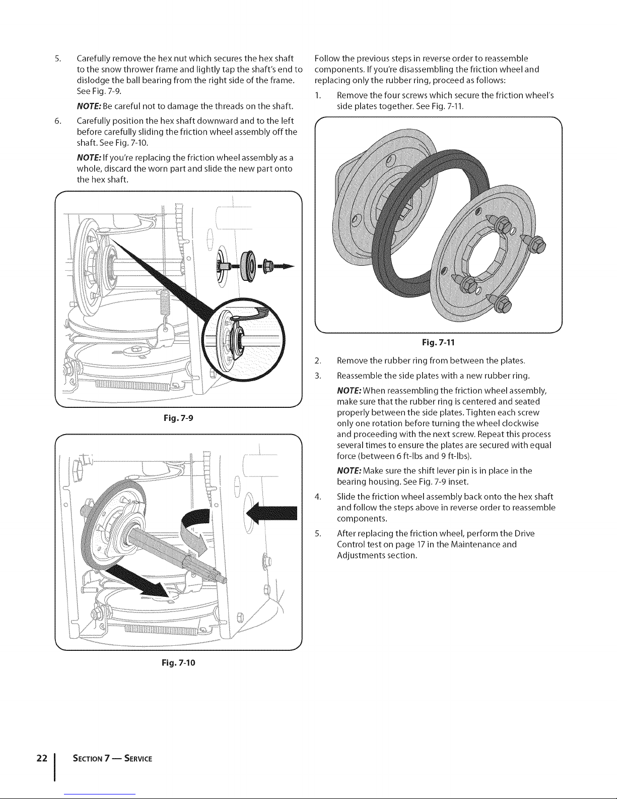
5. Carefully remove the hex nut which secures the hex shaft
to the snow thrower frame and lightly tap the shaft's end to
dislodge the ball bearing from the right side of the frame.
See Fig. 7-9.
NOTE: Be careful not to damage the threads on the shaft.
6. Carefully position the hex shaft downward and to the left
before carefully sliding the friction wheel assembly off the
shaft. See Fig. 7-10.
NOTE: If you're replacing the friction wheel assembly as a
whole, discard the worn part and slide the new part onto
the hex shaft.
Follow the previous steps in reverse order to reassemble
components. If you're disassembling the friction wheel and
replacing only the rubber ring, proceed as follows:
1. Remove the four screws which secure the friction wheel's
side plates together. See Fig. 7-11.
Fig. 7=11
Fig. 7-9
2. Remove the rubber ring from between the plates.
3. Reassemble the side plates with a new rubber ring.
NOTE:When reassembling the friction wheel assembly,
make sure that the rubber ring is centered and seated
properly between the side plates. Tighten each screw
only one rotation before turning the wheel clockwise
and proceeding with the next screw. Repeat this process
several times to ensure the plates are secured with equal
force (between 6 ft-lbs and 9 ft-lbs).
NOTE:Make sure the shift lever pin is in place in the
bearing housing. See Fig. 7-9 inset.
4. Slide the friction wheel assembly back onto the hex shaft
and follow the steps above in reverse order to reassemble
components.
5. After replacing the friction wheel, perform the Drive
Control test on page 17 in the Maintenance and
Adjustments section.
Fig. 7-10
SECTION7 -- SERVICE
Page 23

Troubleshooting
Problem
Engine fails to start
Engine running erratically/'
_nconslstent RPM (hunting or
surging)
Engine overheats
Excessive vibration
Loss of power
Cause
1. Choke not in CHOKE position.
2. Spark plug wire disconnected.
3. Fuel tank empty or stale fuel.
4. Engine not primed.
5. Faulty spark plug.
6. Key not in ignition on engine.
1, Eng_nerunmngonCHOKE.
2, Stale fuel,
3, Water or d_rt in fuel system,
4, Carburetor out of adjustment,
5, Engine over-governed
1. Carburetor not adjusted properly.
1, Loose parts or damaged auger,
1. Spark plug wire loose.
2. Gas cap vent hole plugged.
Remedy
1. Move choke to CHOKE position.
2. Connect wire to spark plug.
3. Fill tankwith clean, fresh gasoline.
4. Pnme engine as instructed in the Operation section.
S. Clean, adjust gap, or replace.
6. Insert key fully into the switch.
1, Move choke lever to RUN posmon,
2, Fdl tank with clean, fresh gasohne,
3, Drain fuel tank, Refill w_th fresh fuel,
4, Contact an authonzed Serwce Center,
S, Contact an authonzed Serwce Center,
1, Contact an authorized Serwce Center.
1, Stop engine immediately and disconnect spark plug wire,
Tighten all bolts and nuts. If wbratlon continues, have umt
serwced by an authonzed Serwce Center,
1. Connect and tighten spark plug wire.
2. Remove ice and snow from gas cap. Be certain vent hole
is clear,
Umt fails to propel _tself
Unit fails to discharge snow
Engine fails to start 1, Connect one end of the extension cord to the electnc
Chute fails to easily rotate 180 1. Chute assembled incorrectly. 1. Unassemble chute control and reassemble as directed in
degrees the Assembly & Set-up section.
Chute does not stay stationary 1, Insufficient tension apphed to chute 2, Refer to the Maintenance & Adjustments section to adjust
while throwing snow using an control, chute preload,
overhead chute control,
1, Dnve control cable _nneed of
adjustment,
2, Dnve belt loose or damaged,
3, Friction wheel worn,
1. Chute assembly clogged.
2. Foreign object lodged in auger,
3. Auger control cable in need of
adjustment.
4. Auger belt loose or damaged.
5. Shear pin(s) sheared.
1, Extension cord not connected (when
using electnc start button, on models so
equlpped)
1, Adjust dnve control cable, Refer to Maintenance &
Adjustments section,
2, Replace dnve belt, Refer to Serwce section
3, Replace fnctlon wheel, Refer to Serwce section,
1. Stop engine immedtately and disconnect spark plug wire.
Clean chute assembly and inside of auger housing with
clean-out tool or a stick.
2. Stop engine immediately and disconnect spark plug wire.
Remove object from auger with clean-out tool or a stick.
3. Refer to Auger Control Test.
4. Refer to Maintenance & Adjustments section.
5. Replace with new shear pin(s).
starter outlet and the other end to a three-prong 120-volt,
grounded, AC outlet,
23
Page 24

ReplacementParts
Component J Part Number and Description
9
929-0071A
954-04050
954-04260
954-04195
954-04201A
684-04159
684-04153
935-04054
725-1629
738-04124A
714-04040
784-5580
731-06439
790-00091
731-05984A
Extension Cord, 1lOV
Auger Drive Belt (24")
Wheel Drive Belt (24")
Auger Drive Belt (26", 28" & 30")
Wheel Drive Belt (26", 28" & 30")
Friction Wheel Assembly (500 Series)
Friction Wheel Assembly 600 Series)
Friction Wheel Rubber (all models)
Lamp
Shear Pin, 1.50
Bow-tie Cotter Pin
Slide Shoe, Standard (Steel)
Slide Shoe, Standard (Polymer)
Slide Shoe, Deluxe (Steel)
Slide Shoe, Deluxe (Polymer)
931-2643 Chute Clean-out Tool
790-00120 Shave Plate, 24"
790-00121 Shave Plate, 26"
790-00118 Shave Plate, 28"
790-00119 Shave Plate, 30"
951-10630 Key
NOTE: Download a complete Parts Manual, refer to customer support on page 2. Be sure to have your model number and serial
number ready. Refer to page 2 for more information regarding locating your model and serial numbers.
Page 25

TWOYEARLiMiTEDWARRANTY
The limited warranty set forth below is given by MTD Products Limited with respect to new merchandise purchased and used in
Canada and/or its territories and possessions (either entity respectively, "MTD").
MTD warrants this product (excluding its normal wear parts as described below) against defects in material and workmanship for
a period of two (2) years commencing on the date of original purchase and will, at its option, repair or replace, free of charge, any
part found to be defective in materials or workmanship. This limited warranty shall only apply if this product has been operated
and maintained in accordance with the Operator's Manual furnished with the product, and has not been subject to misuse, abuse,
commercial use, neglect, accident, improper maintenance, alteration, vandalism, theft, fire, water, or damage because of other peril or
natural disaster. Damage resulting from the installation or use of any part, accessory or attachment not approved by MTD for use with
the product(s) covered by this manual will void your warranty as to any resulting damage.
Normal wear parts are warranted to be free from defects in material and workmanship for a period of thirty (30) days from the date
of purchase. Normal wear parts include, but are not limited to items such as: batteries, belts, blades, blade adapters, grass bags, rider
deck wheels, seats, snow thrower skid shoes, friction wheels, shave plates, auger spiral rubber, tires, engine oil, air filters and spark
plugs.
HOW TO OBTAIN SERVICE: Warranty service is available, WITH PROOF OF PURCHASE, through your local authorized service dealer. To
locate the dealer in your area contact MTD Products Limited, Kitchener, ON N2G 4J1, or call 1-800-668-1238 or log on to our Web site
at www.mtdcanada.com.
This limited
No implied warranty, including any implied warranty of merchantability of fitness for a particular purpose, applies after
the applicable period of express written warranty above as to the parts as identified. No other express warranty, whether
written or oral, except as mentioned above, given by any person or entity, including a dealer or retailer, with respect to any
product, shall bind MTD. During the period of the warranty, the exclusive remedy is repair or replacement of the product as
set forth above.
The provisions as set forth in this warranty provide the sole and exclusive remedy arising from the sale. MTD shall not be
liable for incidental or consequential loss or damage including, without limitation, expenses incurred for substitute or
replacement lawn care services or for rental expenses to temporarily replace a warranted product.
Some jurisdictions do not allow the exclusion or limitation of incidental or consequential damages, or limitations on how long an
implied warranty lasts, so the above exclusions or limitations may not apply to you.
In no event shall recovery of any kind be greater than the amount of the purchase price of the product sold. Alteration of safety
features of the product shall void this warranty. You assume the risk and liability for loss, damage, or injury to you and your
property and/or to others and their property arising out of the misuse or inability to use the product.
This limited warranty shall not extend to anyone other than the original purchaser or to the person for whom it was purchased as a
gift.
HOW LOCAL LAWS RELATE TO THIS WARRANTY: This limited warranty gives you specific legal rights, and you may also have other
rights that vary in different jurisdictions.
warranty does not provide coverage in the following cases:
a.
The engine or component parts thereof. These items may carry a separate manufacturer's warranty. Refer to applicable
manufacturer's warranty for terms and conditions. The Powermore engine is not excluded under this agreement.
b.
Log splitter pumps, valves, and cylinders have a separate one-year warranty.
c.
Routine maintenance items such as lubricants, filters, blade sharpening, tune-ups, brake adjustments, clutch adjustments,
deck adjustments, and normal deterioration of the exterior finish due to use or exposure.
d. Service completed by someone other than an authorized service dealer.
e. MTD does not extend any warranty for products sold or exported outside of Canada, including possessions and
territories.
f.
Replacement parts that are not genuine MTD parts.
g.
Transportation charges and service calls.
h.
If Products are used commercially. (MTD may separately offer Limited Commercial Warranties on certain select products.
Ask your dealer or retailer for details or contact MTD Service for more information.)
IMPORTANT: Owner must present Original Proof of Purchase to obtain warranty coverage.
MTD Products Ltd., P.O. BOX 1386, KITCHENER, ON N2G 4J1; Phone: 1=800=668=1238
12.08.06
25
Page 26

FEDERALand/orCALIFORNIAEMISSIONCONTROLWARRANTY STATEMENT
YOUR WARRANTY RIGHTS AND OBLIGATIONS
MTDConsumerGroupInc,the UnitedStatesEnvironmentalProtectionAgency(EPA),and,forthoseproductscertifiedfor sale in the stateofCalifornia,the
CaliforniaAirResourcesBoard(CARB)are pleasedtoexplainthe emission(evaporativeand/or exhaust)controlsystem(ECS)warrantyonyouroutdoor2006
andlater smalloff-roadspark-ignitedengineandequipment(outdoorequipmentengine)InCalifornia,new outdoorequipmentenginesmustbe designed,built and
equippedtomeetthe State'sstringentanti-smogstandards(inotherstates,1997andlatermodelyear equipmentmustbedesigned,built,and equippedto meet
theU.S.EPAsmalloff-road,sparkignitionengineregulations.MTDConsumerGroupIncmustwarrantthe ECSonyour outdoorequipmentengineforthe periodof
timelistedbelowprovidedtherehasbeen noabuse,neglector impropermaintenanceofoutdoorequipmentengine.
YourECSmayincludeparts suchas thecarburetor,fuel-injectionsystem,the ignitionsystem,catalyticconverter,fueltanks,fuel lines,fuelcaps,valves,canisters,
filters,vaporhoses,clamps,connectors,andotherassociatedemission-relatedcomponents.
Wherea warrantableconditionexists,MTDConsumerGroupIncwill repairyouroutdoorequipmentengineat nocost toyouincludingdiagnosis,partsand labor.
MAN UFACTURER'S WARRANTY COVERAGE:
Thisemissioncontrolsystemiswarrantedfortwo years. If anyemission-relatedpartonyouroutdoorequipmentengineis defective,the partwill berepairedor
replacedby MTDCONSUMERGROUPINC.
OWNER'S WARRANTY RESPONSIBILITIES:
Asthe outdoorequipmentengineowner,youare responsiblefor performanceofthe requiredmaintenancelistedinyourowner'smanual.MTDConsumerGroup
Increcommendsthat you retainallreceiptscoveringmaintenanceonyouroutdoorequipmentengine,butMTDConsumerGroupInc cannotdeny warrantysolely
forthe lackof receipts.
Asthe outdoorequipmentengineowner,youshouldhoweverbe awarethat MTDConsumerGroupIncmaydenyyouwarrantycoverageifyour outdoorequipment
engineor a parthasfaileddue toabuse,neglect,or impropermaintenanceor unapprovedmodifications.
Youare responsiblefor presentingyouroutdoorequipmentengineto MTDConsumerGroupInc'sdistributioncenterorservicecenteras soon asthe problem
exists.Thewarrantyrepairsshouldbecompletedin a reasonableamountoftime, notto exceed30 days. If youhaveaquestionregardingyour warrantycoverage,
youshouldcontactthe MTDConsumerGroupIncServiceDepartment.
In the U.S.A.: MTD LLCat RO. Box361131,Cleveland,Ohio 44136-0019,or call 1-800-800-7310or 1-330-220-4683or
logon to our Web site at www.mtdproducts.com.
In Canada: MTD Products Limited,Kitchener,ON N2G 4J1, or call 1-800-668-1238or log on to our Web site at www.mtdcanada.com.
GENERAL EMISSIONS WARRANTY COVERAGE:
MTDConsumerGroupIncwarrantsto the ultimatepurchaserandeachsubsequentpurchaserthattheoutdoorequipmentengineis: Designed,builtand equipped
soasto conformwithall applicableregulations;andfreefromdefectsin materialsandworkmanshipthatcausethe failureof a warrantedparttobe identicalin all
materialrespectstothat partasdescribedin MTDConsumerGroupInc'sapplicationforcertification.
Thewarrantyperiodbeginsonthedatetheoutdoorequipmentengineisdeliveredto anultimatepurchaserorfirst placedinto service.The warrantyperiodistwo
years.
Subjecttocertainconditionsand exclusionsasstatedbelow,the warrantyonemission-relatedpartsis asfollows:
1. Anywarrantedpartthatisnotscheduledfor replacementasrequiredmaintenancein thewritteninstructionssupplied,is warrantedforthe warrantyperiod
statedabove.Ifthe part fails duringthe periodofwarrantycoverage,thepartwill berepairedor replacedbyMTDConsumerGroupIncaccordingto subsection
(4)below.Anysuchpart repairedor replacedunderwarrantywillbewarrantedforthe remainderof the period.
2. Anywarrantedpartthatisscheduledonlyfor regularinspectionin the writteninstructionssuppliedis warrantedforthe warrantyperiodstatedabove.Any such
partrepairedor replacedunderwarrantywill bewarrantedforthe remainingwarrantyperiod.
3. Anywarrantedpartthatisscheduledfor replacementas requiredmaintenanceinthewritten instructionssuppliediswarrantedforthe periodoftimebeforethe
firstscheduledreplacementdatefor that part.If the partfails beforethefirst scheduledreplacement,the partwill berepairedorreplacedby MTDConsumer
GroupIncaccordingto subsection(4)below.Anysuchpartrepairedor replacedunderwarrantywillbe warrantedforthe remainderof the periodpriortothe
firstscheduledreplacementpointfor the part.
4. Repairor replacementofanywarrantedpart underthe warrantyprovisionshereinmustbeperformedat a warrantystationat no chargetothe owner.
5. Notwithstandingthe provisionsherein,warrantyservicesor repairswill be providedat allof ourdistributioncentersthatare franchisedto servicethe subject
enginesor equipment.
6. Theoutdoorequipmentengineownerwill notbe chargedfordiagnosticlaborthatisdirectlyassociatedwithdiagnosisof a defective,emission-relatedwar-
rantedpart, providedthatsuchdiagnosticworkis performedata warrantystation.
7. MTDConsumerGroupIncisliablefor damagesto otherengineor equipmentcomponentsproximatelycausedbya failure underwarrantyof any warranted
part.
8. Throughouttheoff-roadengineand equipmentwarrantyperiodstatedabove,MTDConsumerGroupInc will maintaina supplyof warrantedpartssufficientto
meetthe expecteddemandfor suchparts.
Page 27

9.Anyreplacementpartmaybeusedintheperformanceofanywarrantymaintenanceorrepairsandmustbeprovidedwithoutchargetotheowner.Suchusewill
notreducethewarrantyobligationsofMTDConsumerGroupInc.
10.Add-onormodifiedpartsthatarenotexemptedbytheAirResourcesBoardmaynotbeused.Theuseofanynon-exemptedadd-onormodifiedpartsbythe
ultimatepurchaserwillbegroundsfordisallowingawarrantyclaims.MTDConsumerGroupIncwillnotbeliabletowarrantfailuresofwarrantedpartscaused
bytheuseofanon-exemptedadd-onormodifiedpart.
WARRANTED PARTS:
Therepairor replacementofanywarrantedpartotherwiseeligiblefor warrantycoveragemaybeexcludedfromsuchwarrantycoverageif MTDConsumerGroup
Incdemonstratesthatthe outdoorequipmentenginehasbeenabused,neglected,orimproperlymaintained,andthatsuchabuse,neglect,or impropermainte-
nancewasthe direct causeof the needfor repairor replacementofthe part.Thatnotwithstanding,anyadjustmentofa componentthat hasa factoryinstalled,
andproperlyoperating,adjustmentlimitingdeviceisstill eligiblefor warrantycoverage.Further,thecoverageunderthis warrantyextendsonly to partsthatwere
presentonthe off-roadengineandequipmentpurchased.
Thefollowingemissionwarrantypartsare covered(ifapplicable):
(1)FuelMeteringSystem
• Cold start enrichmentsystem(softchoke)
• Carburetorand internalparts(or fuel injectionsystem)
• Fuelpump
• Fueltank
(2)Air InductionSystem
• Air cleaner
• Intakemanifold
(3) IgnitionSystem
• Sparkplug(s)
• Magnetoignitionsystem
(4) ExhaustSystem
• Catalyticconverter
• SAI(Reedvalve)
(5) MiscellaneousItemsUsedin AboveSystem
• Vacuum,temperature,position,timesensitivevalvesand switches
• Connectorsandassemblies
(6) EvaporativeControl
• Fuelhose
• Fuelhoseclamps
• Tetheredfuelcap
• Carboncanister
• Vapor lines
NOTE:Ifyourequirewarrantyservicein CanadaandyourproductwassoldbyMTDProductsLimitedwithinCanadato theretaileryoupurchasedit
fromin CanadathentheMTDConsumerGroupIncportionofthiswarrantywillbe honoredbyMTDProductsLimitedin Canada,
GDOC-100223CNRev.A
Page 28

 Loading...