

Page 1
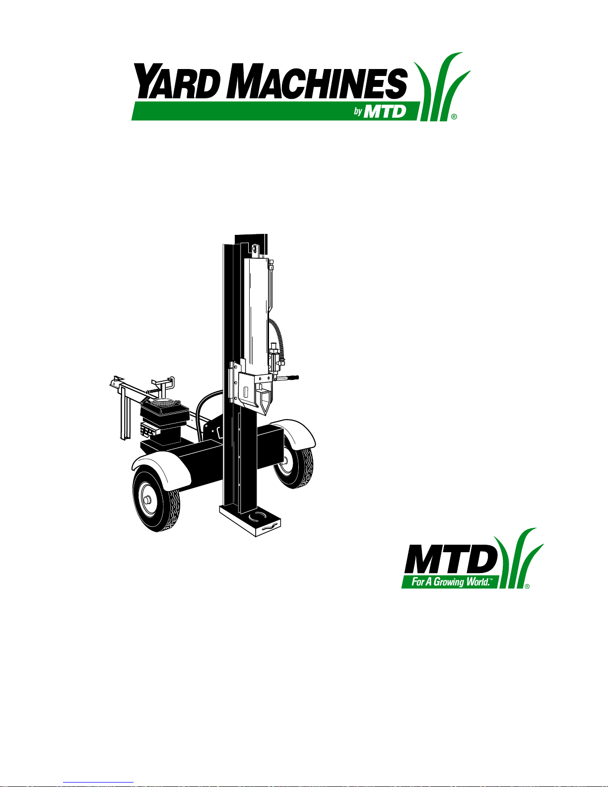
OPERATOR’S MANUAL
LOG SPLITTER
MODELS
550 and 560
IMPORTANT: READ SAFETY RULES AND INSTRUCTIONS CAREFULLY
Warning:
covered, brush-covered or grass-covered land unless the engine’s exhaust system is equipped with a spark arrester meeting
applicable local or state laws (if any). If a spark arrester is used, it should be maintained in effective working order by the operator.
In the State of California the above is required by law (Section 4442 of the California Public Resources Code). Other states may have
similar laws. Federal laws apply on federal lands. A spark arrester for the muffler is available through your nearest engine authorized
service dealer or contact the service department, P.O. Box 368022 Cleveland, Ohio 44136-9722.
This unit is equipped with an internal combustion engine and should not be used on or near any unimproved forest-
MTD PRODUCTS INC. P.O. BOX 368022 CLEVELAND, OHIO 44136-9722
PRINTED IN U.S.A. FORM NO. 770-0363A
Page 2

SECTION 1: IMPORTANT RULES FOR SAFE OPERATION
WARNING:
THIS SYMBOL POINTS OUT IMPORTANT SAFETY INSTRUCTIONS WHICH, IF
NOT FOLLOWED, COULD ENDANGER THE PERSONAL SAFETY AND/OR PROPERTY OF
YOURSELF AND OTHERS. READ AND FOLLOW ALL INSTRUCTIONS IN THIS MANUAL
BEFORE ATTEMPTING TO OPERATE YOUR LOG SPLITTER. FAILURE TO COMPLY WITH
THESE INSTRUCTIONS MAY RESULT IN PERSONAL INJURY. WHEN YOU SEE THIS SYMBOL
HEED ITS WARNING.
WARNING:
The Engine Exhaust from this product contains chemicals known to
the State of California to cause cancer, birth defects or other reproductive harm.
DANGER:
this manual. As with any type of power equipment, carelessness or error on the part of the operator
can result in serious injury. If you violate any of these rules, you may cause serious injury to
yourself or others.
Your log splitter was built to be operated according to the rules for safe operation in
1. TRAINING
• Before operating this splitter, read and understand
this operator’s manual completely. Become
familiar with it for your own safety. To fail to do so
may cause serious injury. Do not allow anyone to
operate your splitter who has not read this manual.
Keep this manual in a safe place for future and
regular reference and for ordering replacement
parts.
• Never use your splitter for any other purpose than
splitting wood. It is designed for this use and any
other use may cause an injury. Your log splitter is
a precision piece of power equipment, not a toy.
Therefore, exercise extreme caution at all times.
• Never allow children to operate your log splitter.
Do not allow adults to operate it without proper
instruction. Only persons well acquainted with
these rules of safe operation should be allowed to
use your log splitter.
• Only the operator is to be near your log splitter
during use. Keep all others, including pets and
children, a minimum of 20 feet away from your
work zone. Flying wood can be hazardous. If a
helper is assisting in loading logs, never activate
the control until the helper is clear of the area.
More accidents occur when more than one person
operates the log splitter than at any other time.
• No one should operate this unit while intoxicated
or while taking medication that impairs the senses
or reactions. A clear mind is essential for safety.
Never allow a person who is tired or otherwise not
alert to use your splitter.
2. PREPARATION
• Never wear loose clothing or jewelry that can be
caught by moving parts of your log splitter and pull
you into it. Keep clothing away from all moving
parts of your log splitter.
• Wear proper head gear to keep hair away from
moving parts. Always wear protective hearing
devices as needed.
• Always wear safety shoes. A dropped log can
seriously injure your foot.
• Always wear safety glasses or goggles while
operating your splitter. A piece of splitting log could
fly off and hit your eyes.
• Wear leather work gloves. Be sure they are tight
fitting without loose cuffs or draw strings.
• Use your log splitter in daylight, or under good
artificial light.
• Never operate your splitter on slippery, wet, muddy
or icy surfaces. Safe footing is essential in
preventing accidents.
• Never operate your splitter while attached to a
towing vehicle.
• Only operate your splitter on level ground and not
on the side of a hill. It could tip, or rolling logs or
poor footing could cause an accident. Operating
the splitter on level ground also prevents the
spillage of gasoline from the fuel tank.
• Never attempt to move the log splitter over hilly or
uneven terrain without a tow vehicle or adequate
help.
• Always block the wheels to prevent movement of
log splitter while in operation.
• Check the fuel before starting the engine. Gasoline
is an extremely flammable fuel. Do not fill the
gasoline tank indoors, when the engine is running,
or while the engine is still hot. Replace gasoline
cap securely and wipe off any spilled gasoline
before starting the engine as it may cause a fire or
explosion.
2
Page 3
•
• Both ends of each log must be cut as square as
possible to help prevent the log from riding out of
the splitter during operation.
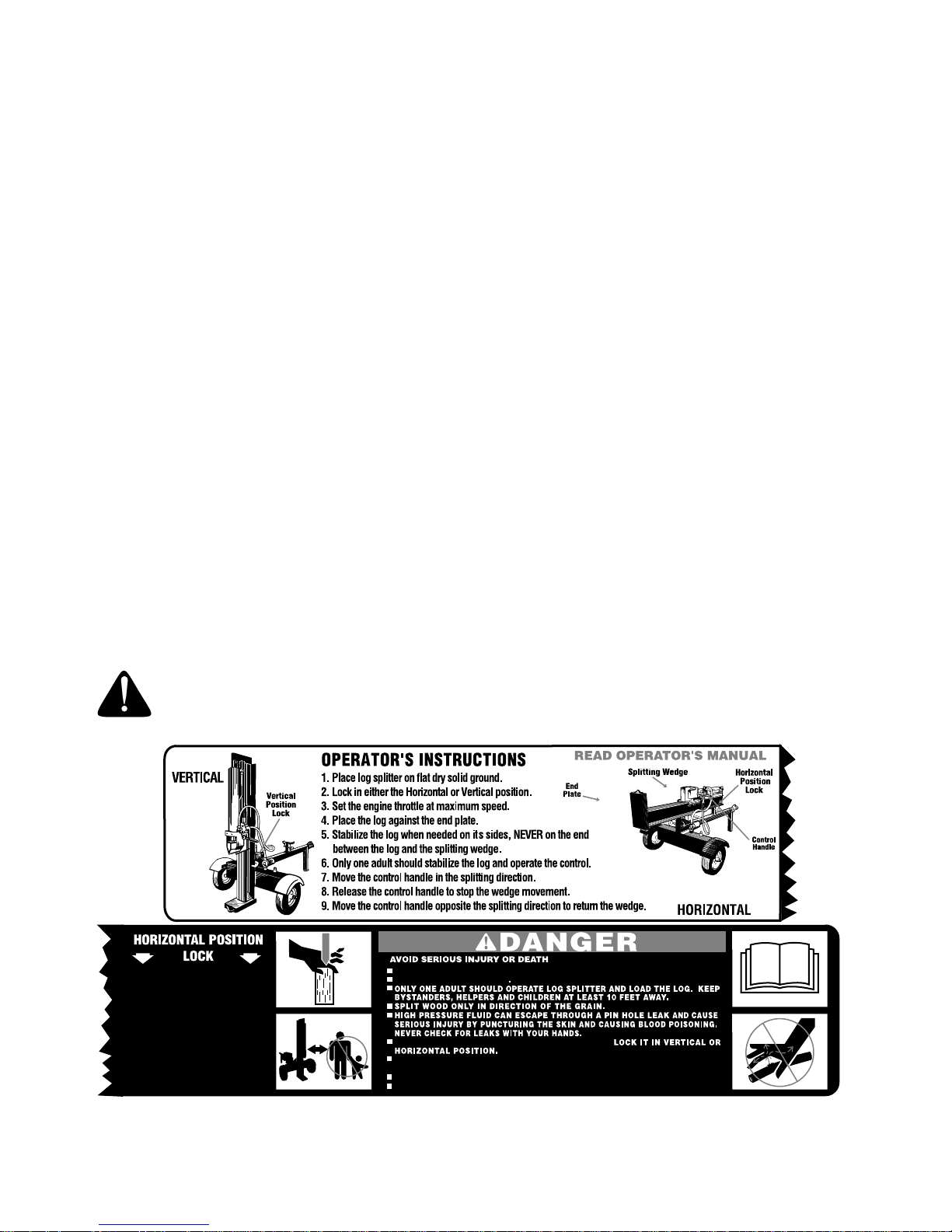
3. OPERATION
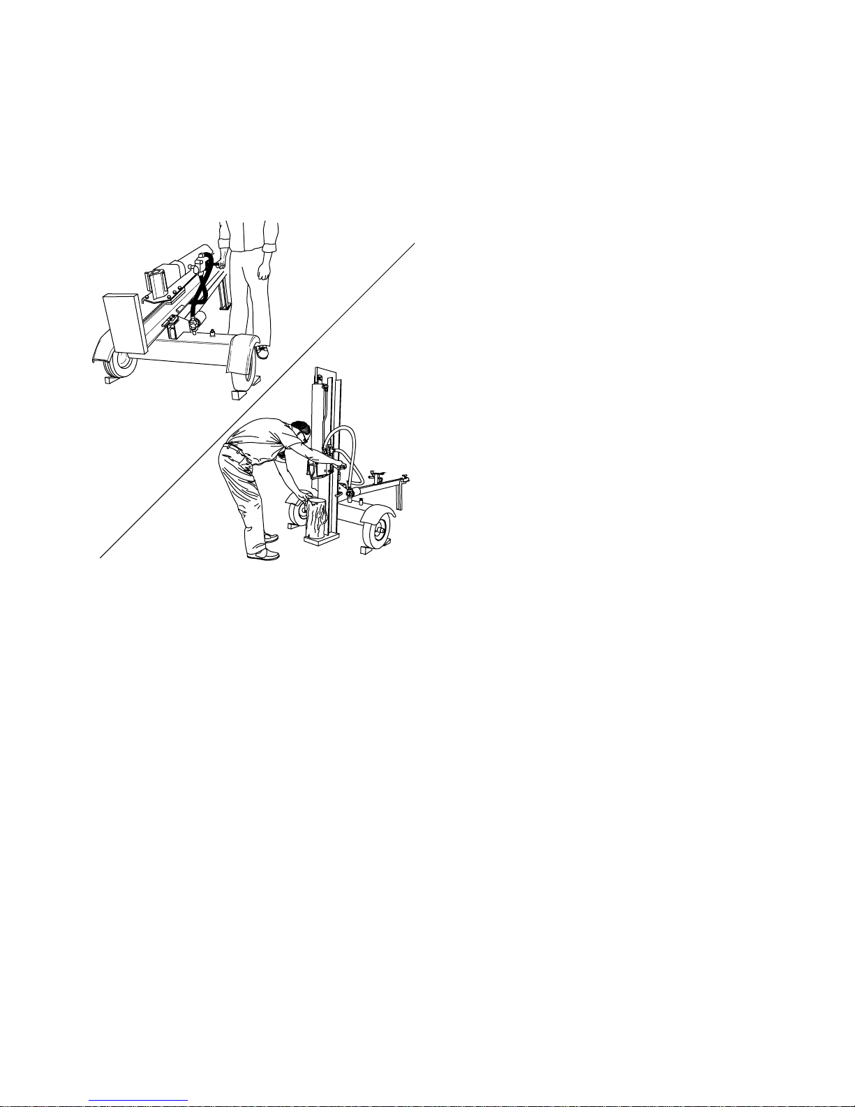
Vertical Operating Position: Stand in front of the
log splitter.
Horizontal Operating Position: Stand behind the
reservoir tank. See illustrations.
• Know how to stop the unit and disengage the
controls.
• Never place hands or feet between log and
splitting wedge or between log and end plate
during forward or reverse stroke. To do so may
result in crushed or amputated fingers or toes, or
worse, you may lose an arm or foot.
• Do not straddle the splitter when using it. A slip in
any position could result in a serious injury.
• Do not step over your log splitter when the engine
is running. You may trip or accidentally activate the
splitting wedge if you step over. If you need to get
to the other side, walk around.
• Never try to split two logs on top of each other.
One may fly out and injure you.
• When loading the log splitter, place your hands on
the side of the log, not at the ends. Never attempt
to load your splitter while the splitting wedge is in
motion. You may get caught by the wedge and
injured.
• Only use your hand to operate the splitting wedge
or control lever. Never use your foot or a rope or
any other extension device. This could result in
your inability to stop your splitter quickly enough to
avoid injury.
• Always keep fingers away from any cracks that
open in the log during splitting operation. They can
quickly close and pinch or amputate your fingers.
• Never attempt to split woods across the grain.
Some types of wood may burst or fly out of your
splitter and result in injury to you or a bystander.
• For logs that are not cut square, the longest
portion of the log should be rotated down and the
most square end placed against the splitting
wedge.
• Keep your work area clean. Immediately remove
split wood around your splitter so that you do not
stumble over it. Clean chips and dirt off end plate
(wood platform) after each log is split, or whenever
necessary to maintain flat contact between wood
and end plate (platform).
• Never move the log splitter while the engine is
running.
• Never leave your log splitter unattended with the
engine running. Shut off the engine if you are
leaving your splitter, even for a short period of
time. Someone could accidentally activate the
splitting wedge and be injured.
• Do not run engine in an enclosed area. Exhaust
gases contain carbon monoxide. This odorless gas
can be deadly when inhaled.
• Be careful not to touch the muffler after the engine
has been running. It will be HOT!
• If the equipment should start to vibrate abnormally,
stop the engine and check immediately for the
cause. Vibration is generally a warning of trouble.
• When cleaning, repairing or inspecting, make
certain all moving parts have stopped. Disconnect
the spark plug wire and keep the wire away from
the plug to prevent accidental starting.
4. CUSTOMER RESPONSIBILITIES
• Do not operate your splitter in poor mechanical
condition or when in need of repair.
• Periodically check that all nuts, bolts, screws, hose
clamps and hydraulic fittings are tight to be sure
equipment is in safe working condition. Where
appropriate, check all safety guards and shields to
be sure they are in the proper position. Never
operate your splitter with safety guards, shields or
other protective features removed. These safety
devices are for your protection.
• Replace all damaged or worn parts such as
hydraulic hoses and fittings immediately with
manufacturer approved replacement parts.
• Do not change the engine governor settings or
overspeed the engine. This increases the hazard
of personal injury. The maximum engine speed is
preset by the manufacturer and is within safety
limits.
• Do not alter your splitter in any manner such as
attaching a rope or extension to the control lever or
3
Page 4
adding to the width or height of the wedge. Such
alterations may cause your splitter to be unsafe.
• Perform all recommended maintenance
procedures before you use your splitter.
• Do not service or repair your log splitter without
disconnecting the spark plug wire and moving it
away from the spark plug.
• Never store the equipment with gasoline in the
tank inside of a building where ignition sources are
present, such as hot water and space heaters,
clothes dryers and the like. Allow the engine to
cool before storing in any enclosure.
• Always store gasoline in an approved, tightly
sealed container. Store the container in a cool, dry
place. Do not store in a building where ignition
sources are present.
• To reduce fire hazard, keep engine free of grass,
leaves, wood chips, and excessive grease and oil.
• The hydraulic system of your log splitter requires
careful inspection, along with the mechanical
parts. Be sure to replace frayed, kinked, or
otherwise damaged hydraulic components.
• Fluid escaping from a very small hole can be
almost invisible. Do not check for leaks with your
hand. Escaping fluid under pressure can have
sufficient force to penetrate skin, causing serious
personal injury. Leaks can be located by passing a
piece of cardboard or wood over the suspected
leak and looking for discoloration.
• Should it become necessary to loosen or remove
any hydraulic fitting or line, be sure to relieve all
pressure by shutting off the engine and moving the
control handle back and forth several times.
• Do not remove the cap from the hydraulic tank or
reservoir while your log splitter is running. Hot oil
under pressure could cause injury.
• The pressure relief valve on your splitter is preset
at the factory. Do not adjust the valve. Only a
qualified service technician should perform this
adjustment.
• Completely drain fuel tank prior to storage. This
guards against accumulation of fuel fumes which
could result in a fire hazard.
• Never store log splitter outside without a
waterproof cover. Rain will cause rust on the inside
of the cylinder.
5. TOWING
• This unit should not be towed on any street,
highway or public road without checking the
existing federal, local or state vehicle
requirements. Any licensing or modifications such
as taillights, etc., needed to comply with the
existing federal, local or state vehicle requirements
is the sole responsibility of the purchaser.
• Before towing, be certain the log splitter is
correctly and securely attached to the towing
vehicle, and the safety chains are in place. Leave
slack in chains for turning allowance.
• Do not allow anyone to sit or ride on your splitter.
They can easily fall off and be seriously injured.
WARNING - YOUR RESPONSIBILITY:
Restrict the use of this power machine to persons
who read, understand and follow the warnings and instructions in this manual and on the machine.
KEEP HANDS AW A Y FROM WEDGE, END PLA TE, P ARTLY SPLIT WOOD AND MO VING P ARTS.
HOLD LOG ON IT'S SIDES NOT ON ENDS WHEN LOADING.
OPERATE THE LOG SPLITTER ON LEVEL SURFACE.
WEAR PROTECTIVE W ORK GLO VES, SAFETY SHOES AND SAFETY GLASSES, WA TCH
YOUR FOOTING.
NEVER OPERATE UNDER THE INFLUENCE OF ALCOHOL OR DRUGS.
DO NOT REFUEL A HOT OR RUNNING ENGINE.
READ OPERATOR'S MANUAL
4
Page 5
SECTION 2: IMPORTANT INFORMATION FOR LOG SPLITTER USERS
Always:
• Use clean fluid and check fluid level regularly
• Use Dexron III Automatic Transmission Fluid
or 10W non-foaming hydraulic fluid.
• Use a filter (clean or replace regularly)
• Use a breather cap on fluid reservoir
• Keep end of reservoir return tube below fluid
level
• Make certain pump is mounted and aligned
properly
• Use a flexible ‘‘spider’’ type coupling between
engine and pump driveshafts
• Keep hoses clear and unblocked
• Bleed air out of hoses before operating
• Flush and clean hydraulic system before startup after any malfunction or servicing
• Use ‘‘pipe dope’’ on all hydraulic fittings
• Allow time for warm-up before splitting wood
• Prime the pump before initial start-up by
turning over the engine with spark plug
disconnected
• Split wood with the grain (lengthwise) only
Never:
• Use when fluid is below 20 ° F.,
or above 150 ° F.
• Use a solid engine/pump coupling
• Force pump when mounting
• Operate through relief valve for more than
several seconds
• Attempt to adjust unloading or relief valve
settings without pressure gauges
• Operate with air in hydraulic system
• Use Teflon tape on hydraulic fittings
• Warm up engine apart from pump in cold
weather
• Attempt to cut wood across the grain
SECTION 3: FINDING YOUR MODEL NUMBER
This Operators Manual is an important part of your
new log splitter. It will help you assemble, prepare
and maintain your log splitter. Please read and
understand what it says.
Before you start to prepare your log splitter for its
first use, please locate the model plate and copy the
information from it in this Operators Manual. The
information on the model plate is very important if
XXX-X-XXX-X-XXX XXXXXXXXXXX
Copy the model number here:
MTD PRODUCTS INC
CLEVELAND, OHIO 44136
Copy the serial number here:
you need help from your dealer or the MTD
customer support department.
• Every log splitter has a model plate. You can
locate it by standing behind the unit in the
operating position and looking down at the
hydraulic tank. .
Model Number
Serial Number
Figure 1
5
Page 6

SECTION 4: CALLING CUSTOMER SUPPORT
If you are having difficulty assembling this product
or if you have any question regarding the controls,
operation or maintenance of this log splitter, please
1-800-800-7310
call the Customer Support Department. You can
reach them by calling:
Before you call, make sure that you have both your
model and serial number ready. By having your model
and serial number ready, you help the Customer Support Representative give you faster service.
SECTION 5: CONDITIONS WHICH WILL VOID YOUR WARRANTY
1. Failure to maintain proper fluid level in reservoir
will void your warranty, causing permanent
damage to pump by allowing air to be drawn
into pump. Fluid will become foamy. Refer to
‘‘Initial Preparation’’ in the Operation section of
this manual.
2. Changing the relief valve setting or pressure
adjustment of control valve without proper
knowledge and instruction from the factory will
void your warranty. A very minor adjustment
could destroy the structural and safety limits for
which the unit was designed. The system will
produce more power than the structure will
withstand. Higher pressure could cause the
hoses to burst, cylinder to rupture and intense
fluid releases, which could result in serious
personal injury.
3. Disassembling the pump will void your
warranty. If replacement is necessary, merely
disconnect and replace. Do not attempt to
adjust pump settings, as they are adjusted by
the manufacturer at the factory.
4. Use of incorrect hydraulic fluid will void your
warranty. Use only Dexron III automatic
transmission fluid or 10W non-foaming
hydraulic fluid.
5. The flexible pump coupler must be inspected
regularly. Allowing the coupler to deteriorate will
void your warranty. Deterioration of spider insert
and prolonged use after deterioration will
destroy pump bearings and engine bearings,
along with total destruction of coupler hubs.
6. Improper beam lubrication will cause premature
wear and looseness. Lubricate the beam
regularly. Lack of lubrication will void your
warranty.
7. Improper adjustment of splitting wedge will void
your warranty. Become familiar with the proper
tolerance required for adjustment of the splitting
wedge as instructed in the Adjustment section
of this manual.
If wedge is too loose, cylinder beam and wedge
wear will result. Allowing the wedge to loosen
and be used under operating stress will cause
damage which will not be covered under
warranty.
If wedge is too tight, severe beam damage will
result which will not be covered under warranty.
8. Warranty card must be mailed or delivered
directly to factory. Proper information must be
completed and mailed as per instructions. No
warranty records on file may result in delay.
9. Do not overheat the hydraulic system.
Excessive heat will destroy the hydraulic
system with hardened O-rings and excessive
friction.
10. Do not attempt to start in temperatures under
o
20
F. without pre-heating fluid in reservoir.
Excessively cold fluid cannot circulate and draw
into pump. Warranty will be void.
11. Repair any leaks in hydraulic system
immediately. Unattended leaks will cause air to
enter system and/or decrease fluid level in
reservoir, causing damage to the hydraulic
system which will not be covered by warranty.
6
Page 7

SECTION 6: ITEMS REQUIRED FOR ASSEMBLY
QTY DESCRIPTION
(1) Crowbar or Large Screwdriver
(1) Soft Hammer or Mallet
(2) 9/16" Wrenches*
(2) 1/2" Wrenches*
(1) 7/16" Wrench*
(1) 13/16” Wrench*
(1) 7/8” Wrench*
(1) Adjustable Wrench
(1) Screwdriver
(1) Pliers
(1) Knife
(1) Cutters
• Engine Oil
• Unleaded Gasoline
• Dexron III Automatic Transmission Fluid or
10W Non-Foaming Hydraulic Fluid
*Adjustable Wrenches may be used.
SECTION 7: UNPACKING
WARNING:
as parts are very heavy. Mechanical
handling equipment should be used, or
sufficient people to prevent injury.
1. Pry the top, sides and ends off crate using a
crowbar or large screwdriver.
2. Set panels aside to avoid tire punctures or
personal injury.
3. Remove and discard plastic bag that covers unit.
4. Remove wheels and small box from crate.
5. Cut and remove straps which secure parts to
bottom of crate. Unbolt parts which are bolted to
the bottom of the crate.
Exercise extreme caution
CONTENTS OF CRATE
• Reservoir Tank and Engine -Pump Assembly
• Wedge, Beam and Cylinder Assembly
• Tongue Assembly
• Wheels
• Hitch Assembly
• Beam Support/Latch Bracket
• Fenders
CONTENTS OF HARDWARE PACK
• 2 hub caps
• Log Splitter Operators Manual
• 4 bolts
• 4 lock washers
• 4 nuts
• Engine Owners Guide
7
Page 8

SECTION 8: ASSEMBLY
ASSEMBLING THE TONGUE
A
Beam Support
Latch Bracket
Tongue
B
C
A
D
Jack Stand
BC
E
J
H
F
I
K
Hitch
H
I
J
G
H
Ball End
Of Hitch
Figure 2
The hardware that is used to assemble the tongue
will be found in place on the tongue and hitch. The
assembly has been divided into three assemblies A,
B and C. Locate the section of Figure 2 that is
appropriate to the instructions.
ASSEMBLY A (See Figure 2)
Attach the Beam Support - Latch Bracket as follows:
1. Remove two hex bolts (A), lock washers (B)
and hex nuts (C) from the tongue, using two
9/16" wrenches.
2. Place the beam support/latch bracket on the
tongue as shown. Secure with hex bolts (A),
lock washers (B) and hex nuts (C) just
removed. Tighten securely.
ASSEMBLY B (See Figure 2)
Prepare the Jack Stand as follows:
1. The jack stand is in the transport position.
Remove spring pin (E) and clevis pin (D). Pivot
the jack stand to the operating position, and
secure with the clevis pin (D) and spring pin (E).
ASSEMBLY C (See Figure 2)
Attach the hitch as follows:
1. Using two 9/16" wrenches, remove the
hardware (F, G, H, I, J and K) assembled on the
hitch.
2. Place the hitch in position on the end of the
tongue as shown. Insert hex bolt (F) (with H, I
and J attached) through hitch and tongue. Pivot
the first chain link on the hex bolt (F) so it faces
the ball end of hitch.
3. Place other spacer (J), safety chain (I) and flat
washer (H) on hex bolt, with the first link of the
chain also facing the ball end of hitch. Secure
with hex lock nut (G).
4. Secure front of tow hitch to tongue with hex bolt
(K), lock washer (H) and hex nut (G), using the
forward hole in hitch and tongue.
5. Tighten hardware securely using two 9/16"
wrenches.
8
Page 9

ASSEMBLING THE WHEELS, BEAM AND TANK
C
Beam
A
L
Fender
H
G
F
E
I
B
M
J
K
J
Axle
B
A
D
C
The hardware that is used to assemble the wheels,
beam and tank will be found in place on the tank or
in the hardware pack. The assembly has been
divided into three sections A, B and C. Locate the
section of Figure 3 that is appropriate to the
instructions.
Wheel
Figure 3
ASSEMBLY A (See Figure 3)
Attach the wheels to the reservoir tank assembly as
follows:
1. Block up the reservoir tank assembly about 8
inches.
2. Remove and discard plastic shipping caps on
the outside of the wheels.
3. Remove the cotter pin (A), hex slotted nut (B)
and flat washer (C) from each axle.
NOTE:
recommended that you polish the axles of the log
splitter with emory cloth before you install the
wheels.
To maximize bearing life, It is
H
G
Reservoir Tank
4. Place one wheel on each axle, valve stem
facing outward.
5. Place one flat washer (C) just removed on each
axle. Secure with hex slotted nut (B). Tighten
slotted nut until snug, then back off
approximately 1/3 turn or until one of the slots
on the slotted nut lines up with the hole in the
axle.
6. Insert cotter pins (A) through slots in nuts (B)
and holes in axle. Secure by bending the ends
of the cotter pins (A) in opposite directions,
using pliers and a screwdriver.
7. Check the assembly of the wheels. There
should be no side to side play, and the wheels
should spin freely.
8. Place hub caps (D) in position on wheels, and
tap on with a soft hammer or mallet. (It may be
necessary to use a screwdriver to tap on the
raised rib of the hub cap.)
9. Check tires for correct air pressure. See the
side wall of the tires for recommended pressure.
9
Tongue
Page 10

(OPTIONAL FENDERS)
10. Using two 1/2" wrenches, remove the hex nuts
(H), lock washers (G), flat washers (F) and hex
bolts (E) from the tank.
11. Determine the proper assembly holes in the
fender by centering the fenders over the tires
against the tank.
12. Insert hex bolts (E) through flat washers (F) and
holes in fenders and tank. Secure fender with
lock washers (G) and hex nuts (H). Tighten
securely.
ASSEMBLY B (See Figure 3)
Attach the tongue as follows:
1. Remove the two hex bolts (I), lock washers (J)
and hex nuts (K) on the front of the reservoir
tank with two 9/16".
2. Place the tongue in position and secure with
hardware just removed.
3. Remove the reservoir assembly from the blocks.
ASSEMBLY C (See Figure 3)
Attach the beam to the reservoir tank as follows:
1. For shipping purposes, the pressure hose is
attached to the pump on the engine, and to the
control valve on the cylinder. Disconnect the
pressure hose from the adapter on the pump.
2. This step will require two people. Stand the
wedge, beam and cylinder assembly upright,
with cylinder to the top.
WARNING:
assembly is very heavy.
3. Remove cotter pin (M) and clevis pin (L),
located beneath the beam assembly. Move the
reservoir tank assembly in position against the
beam. Line up holes by lifting hitch end of
tongue.
4. Insert clevis pin (L) just removed through
welded brackets on beam and reservoir tank
assembly. Secure with cotter pin (M), bending
the ends of the pin in opposite directions.
Use extreme caution as
A TT ACHING THE HOSES
Control Valve
Attach
Here
Filter
Attached To
Reservoir Tank
Attached
To Cylinder
Return Hose
Attach Here
Pump
Pressure Hose
Attached
To Engine
Attached To
Reservoir Tank
Suction Hose
RETURN HOSE
1. The return hose is attached to the top of the
control valve. Loosen the hose clamp on the
free end of the hose using a screwdriver. Cut
the securing strap.
Figure 4
2. Remove the protective cap from the fitting on
top of the filter head. Attach the end of the hose
to the fitting on top of the filter. Place the hose
clamp at the base of the fitting, and tighten
securely.
10
Page 11

PRESSURE HOSE
1. The pressure hose is attached to the control
valve. Route the hose between the beam and
the tongue. Secure the pressure hose to the
adapter on the side of the pump, using a 7/8"
wrench.
PREP ARING THE ENGINE
1. Place the log splitter on a firm, level surface.
2. Fill engine with oil as instructed in the separate
engine manual packed with your log splitter.
3. Fill engine with gasoline as instructed in the
separate engine manual packed with your log
splitter.
PREPARING THE LOG SPLITTER
1. Lubricate the beam area where splitting wedge
will slide with engine oil (DO NOT USE
GREASE). Make certain to oil both front and
back of the beam face.
2. Remove reservoir vent plug. Refer to Figure 4.
3. Fill the reservoir tank as follows. Using Dexron
III automatic transmission fluid, or 10W nonfoaming hydraulic fluid, fill reservoir to the top.
Replace vent plug securely.
NOTE:
depending on the log splitter model. The large tank
has a capacity of approximately 7 gallons. The
small tank has a capacity of approximately 4
gallons.
4. Disconnect the spark plug wire. Prime the pump
5. Reconnect the spark plug wire.
6. Start engine.
7. Use the control handle to engage the wedge to
8. Now retract the wedge.
9. Refill tank to within 1-1/2" to 2" from the top of
10. Extend and retract the wedge fully 10 to 12
11. Refill the reservoir to within 1-1/2" to 2" from the
There are two reservoir tank capacities
by pulling the recoil starter, to turn the engine
over, approximately 10 times.
the far extended position.
the tank.
complete cycles to remove trapped air in the
system (system is ‘‘self-bleeding’’).
top of the tank. Much of the original fluid has
been drawn into the cylinder and hoses. Make
certain to refill the reservoir, to prevent extreme
damage to the hydraulic pump. Failure to refill
the tank will void your warranty.
HYDRAULIC OIL ONLY
10 WEIGHT AW OR DEXRON III
FILL TO TOP
MAINTAIN WITHIN 1.5” TO 2” FROM TOP
AT ALL TIMES - NEVER RUN BELOW
THIS LEVEL. PUMP WILL BE RUINED.
OVER FILL WILL FLOW OUT CAP.
SECTION 9: CONTROLS
ENGINE CONTROLS
See the separate engine owners guide that was
shipped with your log splitter.
LOG SPLITTER CONTROLS
CONTROL HANDLE
The control handle has three positions. Read the
following descriptions of the three positions.
NOTE:
plug as the system builds heat and the fluid
expands and seeks its own level.
Neutral:
position when handle is released. Splitting wedge
stops in place.
Disengage:
Splitting wedge moves toward the cylinder. The
control handle will lock in the disengage position,
and will return to neutral automatically when the
disengage stroke is complete.
Some fluid may overflow from the vent
WARNING:
splitter without the proper amount of
transmission fluid in the reservoir tank.
Control handle will return to neutral
Pull the control handle up or back.
Do not operate the log
Splitting:
down. Splitting wedge moves toward the end plate.
Push the control handle forward or
11
Page 12

BEAM LOCKS
There are two beam locks one for each operating
position. See Figure 5 for the locations.
Vertical:
the oil filter.
The vertical beam lock is located next to
SECTION 10: OPERATION
BEFORE EACH USE
1. Remove the vent plug and check the fluid level.
Fluid level should be 1-1/2" to 2" from the top of
the tank.
2. Check the engine oil level as instructed in the
separate engine owners manual shipped with
you log splitter.
IMPORTANT:
instructed. Low fluid level will damage the pump and
void your warranty.
3. Lubricate the beam area where splitting wedge
will slide with engine oil (DO NOT USE
GREASE). Make certain to oil both front and
back of the beam face.
4. Fill gasoline tank as instructed in separate
engine owners manual shipped with your log
splitter.
5. Make sure fuel shut-off located under gasoline
tank is open (if so equipped).
6. Make sure spark plug wire is attached to spark
plug.
USING THE LOG SPLITTER
Never attempt to cut a log in half sideways. Always
split the log lengthwise. Maximum length of log to
be split is 24".
WARNING:
logs, always use the log splitter in the
vertical position.
WARNING:
safety shoes and safety glasses when
operating log splitter. Ensure safe
footing.
1. Place the log splitter on level, dry and solid
ground.
2. Place the beam in either the horizontal or
vertical position and lock in place with the
appropriate locking rod.
3. Place a chock (block) in front and back of both
wheels.
4. Set the engine throttle at maximum speed.
Reservoir tank must be full as
When splitting heavy
Wear leather work gloves,
Horizontal:
the beam support latch bracket. Refer to Figure 2
for location.
5. Place the log against the end plate. Only split
wood in the direction of the grain.
6. When necessary to stabilize the log, place your
hand only on sides of log, NEVER on the end
between the log and splitting wedge.
7. ONLY ONE ADULT SHOULD STABILIZE THE
LOG AND OPERATE THE CONTROL HANDLE
so the operator has full control over stabilizing
the log and movement of the splitting wedge.
The horizontal beam lock is part of
ST ARTING THE ENGINE
IMPORTANT:
manual for detailed starting instructions for your
model.
1. Place the engine shut-off switch in ON position
or move throttle control lever to FAST position.
Engines with choke lever:
lever in CHOKE position (a warm engine may not
require choking).
Engines with primer:
instructed in separate engine manual.
2. Grasp starter handle and pull rope out slowly
until engine reaches start of compression cycle
(rope will pull slightly harder at this point). Let
the rope rewind slowly.
WARNING:
engine, keep away from muffler and
other heated surfaces on the engine.
3. Pull rope with a rapid, continuous, full arm
stroke. Keep a firm grip on the starter handle.
Let the rope rewind slowly. Do not let starter
handle snap back against starter.
4. Repeat preceding instructions until engine fires.
When engine starts, move choke lever halfway
between CHOKE and RUN.
5. Gradually move choke lever to RUN position as
engine warms up.
6. If weather is cold, run wedge up and down
beam 6 to 8 times to circulate the hydraulic fluid.
Refer to the separate engine
Place choke
Prime engine as
When restarting a warm
12
Page 13

TO STOP ENGINE
1. Move the engine shut-off switch to the OFF
position or move throttle control to STOP
position.
OPERATING POSITIONS
VERTICAL HORIZONTAL
Beam Locks
2. After engine has stopped, disconnect spark
plug wire from spark plug to prevent accidental
starting while equipment is unattended.
Figure 5 *
* Figure 5 shows optional fenders not all unit are
equipped with fenders.
VERTICAL
• For vertical operation, pull the horizontal
beam lock out and pivot it down to release
the beam. Pivot the beam to the vertical
position.
• Lock the beam in the vertical position, by
pulling out on the vertical beam lock and
pivoting it to the left.
• Stand in front of the log splitter. Operate the
control handle with your right hand and
stabilize the log, if necessary, with your left
hand. See Figure 5.
HORIZONTAL
• For horizontal operation, pull the vertical
position release rod out and pivot it down to
release the beam. Pivot the beam to the
horizontal position.
• Lock the beam in the horizontal position, by
pulling out on the horizontal beam lock and
pivoting it to the left.
• Stand behind the reservoir tank. Operate the
control handle with your right hand and
stabilize the log, if necessary, with your left
hand. See Figure 5.
CONTROL HANDLE POSITIONS
• Move control handle FORWARD or DOWN to
split wood.
• Release the control handle to stop the wedge
movement.
• Move control handle BACK or UP to return
the wedge.
TRANSPORTING THE LOG SPLITTER
1. Lower the beam to its horizontal position. Make
certain the beam is locked securely with the
horizontal beam lock.
2. Remove the quick release pin which secures
the jack stand. Support the tongue, and pivot
the jack stand up against the tongue. Secure
with the quick release pin.
3. Attach the hitch to a towing vehicle, making
certain to latch securely.
4. Attach the safety chains to the towing vehicle.
13
Page 14

SECTION 11: ADJUSTMENTS
WARNING: Always stop the engine
and disconnect the spark plug wire
before performing any adjustments.
Attached
To Cylinder
Hex Bolts
Wedge Plate
Adjustment Bolts
Gib Plate
Figure 6
Back Plate
WEDGE PLATE ADJUSTMENT
As normal wear occurs, periodically adjust the bolts
on the side of the wedge plate as follows to
eliminate the excess space between the wedge
plate and the beam. See Figure 6.
Adjust wedge plate as follows:
1. Loosen the three hex bolts on top of the wedge
plate (beneath the splitting wedge).
2. Loosen the jam nuts on the two adjustment
bolts on the side of the gib plate, located
beneath the splitting wedge. Turn the
adjustment bolts in until snug, then back them
off slowly until the wedge assembly will slide on
the beam.
3. Tighten the jam nuts securely against the gib
plate to hold the adjustment bolts in this position.
4. Retighten the three hex bolts on top of the
wedge plate
GIB PLATE ADJUSTMENT
Periodically remove and replace the “gibs” (spacers)
between the wedge plate and the back plate as
follows. See Figure 6.
NOTE: If desired, the gibs may be rotated and/or
turned over for even wear.
1. Remove the center bolt on top of the wedge
plate. Slide the gib plate out.
2. Remove and replace the gibs. Reassemble the
gib plate, making certain flat washers are in
place under the gib plate.
3. Readjust the bolts on the side of the wedge
plate as instructed above.
SECTION 12: MAINTENANCE
WARNING: Always stop the engine
and disconnect the spark plug wire
before performing any maintenance or
repairs.
RESERVOIR FLUID
Check the hydraulic fluid level in the log splitter
reservoir tank before each use. Fluid level should
be 1-1/2" to 2" from the top of the tank.
Change the hydraulic fluid in the reservoir every 100
hours of operation. Disconnect the suction hose
from the bottom of the reservoir tank, and drain the
fluid into a suitable container. Refill using only
Dexron III automatic transmission fluid or 10W nonfoaming hydraulic fluid.
NOTE: Drain the fluid and flush the reservoir tank
and hoses with kerosene whenever any repair work
is performed on the tank, hydraulic pump or valve.
Contaminants in the fluid will damage the hydraulic
components. (Should be performed by an
authorized service dealer.)
WARNING: Use extreme caution
when working with kerosene, as it is an
extremely flammable fluid.
HYDRAULIC FILTER
Change the hydraulic filter every 50 hours of
operation. Use only a 10 micron hydraulic filter.
Order part number 723-0405.
14
Page 15

BEAM AND SPLITTING WEDGE
Lubricate both sides of the beam where it contacts
the splitting wedge with engine oil before each use
to obtain years of service. However, normal wear
will occur. The wedge plate on the log splitter is
designed so the gibs on the side of the wedge plate
can be easily removed and rotated and/or turned
over for even wear. Make certain to readjust the
adjustment bolts so wedge moves freely, but no
excess space exists between the wedge plate and
beam.
HOSE CLAMPS
Check the hose clamps on the suction hose
(attached to side of the pump) for proper tightness
before each use. Check the hose clamps on the
return hose at least once a season.
ENGINE
Refer to the separate engine manual for all engine
maintenance instructions.
FLEXIBLE PUMP COUPLER
The flexible pump coupler is a nylon ‘‘spider’’ insert,
located between the pump and engine shaft. Over a
period of time, the coupler will harden and
deteriorate.
Replacement is needed if you detect vibration or
noise coming from the area between the engine and
the pump. If the coupler fails completely, you will
experience a loss of power.
IMPORTANT: Never hit the engine shaft in any
manner, as a blow will cause permanent damage to
the engine.
When replacing the flexible pump coupler, proceed
as follows. Follow the instructions carefully as the
alignment is critical.
1. Disconnect the spark plug wire, and secure it
away from the spark plug.
2. Drain gasoline from fuel tank or place a piece of
plastic film underneath the gas cap to prevent
gasoline from leaking.
3. Using a 1/2 inch socket with an extension,
remove the three bolts securing the engine to
the engine mounting bracket. The three bolts
can be found under the engine mounting
bracket.
4. Carefully lift engine off mounting bracket and
set aside on a sturdy, level surface.
5. Remove the nylon “spider” insert from the pump
coupling half. You may need a pair of needle
nose pliers to grasp the insert.
6. Place a new “spider” insert into the pump
coupling half.
7. Re-seat the engine making sure to align the
pump and engine coupling halves. The pump
coupling half can be rotated by hand to aid in
alignment. If the two parts are not aligned the
unit will not operate properly and damage could
occur.
8. Secure engine with three bolts removed in step
3.
9. Reattach spark plug wire to spark plug. Be sure
to remove plastic film from under gas cap if
necessary.
TIRES
See sidewall of tire for recommended pressure.
Maximum tire pressure under any circumstances is
30 p.s.i. Equal tire pressure should be maintained
on all tires.
WARNING: Excessive pressure (over
30 p.s.i.) when seating beads may
cause tire/rim assembly to burst with
force sufficient to cause serious injury.
15
Page 16

SECTION 13: OFF-SEASON STORAGE
If the log splitter will not be used for a period longer
than 30 days, the following steps should be taken to
prepare the log splitter for storage.
1. Clean the engine and the entire log splitter
thoroughly.
2. Refer to the engine manual for correct engine
storage instructions.
3. Wipe unit with an oiled rag to prevent rust,
especially wedge and beam.
4. Store unit in a clean, dry area. Do not store next
to corrosive materials, such as fertilizer.
NOTE: When storing any type of power equipment
in an unventilated or metal storage shed, care
should be taken to rustproof the equipment by
coating with a light oil or silicone.
SECTION 14: TROUBLE SHOOTING GUIDE
Problem Possible Cause(s) Corrective Action
Engine fails to start Dirty air cleaner.
Fuel shut-off valve closed (if so
equipped).
Fuel tank empty, or stale fuel.
Choke not in ON position.
Blocked fuel line.
Spark plug wire disconnected.
Faulty spark plug.
Engine runs erratic Unit running on CHOKE.
Spark plug wire loose.
Blocked fuel line or stale fuel.
Water or dirt in fuel system.
Dirty air cleaner.
Carburetor out of adjustment.
Engine
overheats
Will not split logs Reservoir fluid level low. Check and fill reservoir tank as instructed in Operation section of
Leaking cylinder Broken seals.
Engine oil level low.
Dirty air cleaner.
Air flow restricted.
Carburetor not adjusted properly.
Scored cylinder.
Refer to the engine manual packed with your unit.
Open fuel shut-off valve.
Fill tank with clean fresh gasoline. Fuel will not last over thirty
days unless a fuel stabilizer is used.
Move switch to ON position.
Clean fuel line.
Connect wire to spark plug.
Clean, adjust gap or replace.
Move choke lever to OFF position.
Connect and tighten spark plug wire.
Clean fuel line; fill tank with clean fresh gasoline. Fuel will not last
over thirty days unless a fuel stabilizer is used.
Drain fuel tank. Refill with fresh fuel.
Refer to the engine manual packed with your unit.
Refer to the engine manual packed with your unit.
Fill crankcase with proper oil.
Refer to the engine manual packed with your unit.
Stop engine and disconnect spark plug wire. Remove blower
housing and clean.
Refer to the engine manual packed with your unit.
this manual.
Return unit for authorized repair.
Return unit for authorized repair.
Note: For repairs beyond the minor adjustments
above, contact your local authorized service dealer.
16
Page 17

SECTION 15: HYDRAULIC TROUBLE SHOOTING GUIDE
Trouble Possible Causes Corrective Action
Cylinder rod will
not move
Slow cylinder
shaft speed while
extending and
retracting
Engine runs but
wood will not
split, or wood
splits too slowly
Engine stalls
during
splitting
Engine will not
turn or stalls
under low load
conditions
Leaking pump
shaft seal
Broken drive shaft.
Shipping plugs left in
hydraulic hoses.
Set screws in coupling not
adjusted properly.
Loose shaft coupling.
Gear sections damaged.
Damaged relief valve.
Hydraulic lines blocked.
Incorrect oil level.
Damaged directional valve.
Blocked directional valve.
Gear sections damaged.
Excessive pump inlet
vacuum.
Slow engine speed.
Damaged relief valve.
Incorrect oil level.
Contaminated oil.
Directional valve leaking
internally.
Internally damaged cylinder.
Small gear section
damaged.
Pump check valve leaking.
Excessive pump inlet
vacuum.
Incorrect oil level.
Contaminated oil.
Directional valve leaking
internally.
Overloaded cylinder.
Internally damaged cylinder.
Low horsepower/weak
engine.
Overloaded cylinder.
Engine/pump misalignment.
Frozen or seized pump.
Low horsepower/weak
engine.
Hydraulic lines blocked.
Blocked directional valve.
Broken drive shaft.
Engine/pump misalignment.
Gear sections damaged.
Poorly positioned shaft seal.
Plugged oil breather.
Return unit for authorized repair.
Disconnect hydraulic hoses, remove shipping plugs, reconnect hoses.
See operator’s manual for correct adjustment.
Correct engine/pump alignment as necessary. See operator’s manual.
Return unit for authorized repair.
Return unit for authorized repair.
Flush and clean hydraulic system.
Check oil level.
Return unit for authorized repair.
Flush and clean hydraulic system; return unit for authorized repair.
Return unit for authorized repair.
Make certain pump inlet hoses are clear and unblocked-use short, large
diameter inlet hoses.
Return unit for authorized repair.
Return unit for authorized repair.
Check oil level.
Drain oil, clean reservoir, refill, make certain oil return tube is below oil
level.
Return unit for authorized repair.
Return unit for authorized repair.
Return unit for authorized repair.
Return unit for authorized repair.
Make certain pump inlet hoses are clear and unblocked; use short, large
diameter inlet hoses.
Check oil level.
Drain oil, clean reservoir, refill, make certain oil return tube is below oil
level.
Return unit for authorized repair.
Do not attempt to split wood against the grain.
Return unit for authorized repair.
Return unit for authorized repair.
Do not attempt to split wood against the grain. If engine stalls repeatedly,
take unit for authorized repair.
Correct alignment as necessary. See operator’s manual.
Return unit for authorized repair.
Return unit for authorized repair.
Flush and clean hydraulic system.
Flush and clean hydraulic system; return unit for authorized repair.
Return unit for authorized repair.
Correct alignment as necessary. See operator’s manual.
Return unit for authorized repair.
Return unit for authorized repair.
Make certain reservoir is properly vented.
17
Page 18

SECTION 16: ILLUSTRATED PARTS LIST
18
Page 19

REF.
NO.
1 712-0359 Slotted Nut 3/4-16 Thd.
2 714-0162 Cotter Pin 5/32" Dia. x 1-1/4" Lg.
3 734-0873 Hub Cap
4 734-1016 Wheel Ass’y. Comp.
5 736-0351 Fl-Wash. .76" I.D. x 1.5" O.D.
6 741-3028 Bearing Cone
7 736-0921 L-Wash. 1/2" I.D.*
8 737-0192 90° Solid Male Adapter
10 741-3029 Bearing Cup
11 736-0192 Fl-Wash. .531" I.D. x .94" O.D.
15 710-1018 Hex Bolt 1/2-20 x 2.75" Lg. (Grd 8)
16 710-1032 Hex Bolt 3/8-24 x 1.5" Lg.
18 712-0239 Hex L-Nut 1/2-20 Thd.
19 712-3001 Hex Jam Nut 3/8-24 Thd. (Grd 5)
21 732-0583 Comp. Spring 4" Lg.
23 781-0323B Wedge Ass’y.
24 781-0537 Back Plate
25 781-0350A Fixed Side Gib
26 781-0351 Adj. Gib .625 x .625 x 2.00
27 781-0352A Adjustable Gib Shim
28 781-0356 Floating Gib Plate
29 714-0211 External Cotter Pin
30 715-1135 Cylinder Mounting Pin
31 718-0307 Hydraulic Cylinder
32 718-0481 Control Valve
33 727-0471 Metal Pressure Tube
35 737-0153 Return Elbow
37 737-0235 3/4" Hose Barb.
39 710-0521 Hex Bolt 3/8-16 x 3" Lg.
40 710-0411 Hex Bolt 3/8-16 x 4" Lg.
41 710-0944 Hex Bolt 3/8-16 x 4" Lg. (Grd 5)
42 711-0813 Clevis Pin 5/16 x 2.5" Lg.
43 712-0375 Hex L-Nut 3/8-16 Thd.
44 712-0798 Hex Nut 3/8-16 Thd.*
45 713-0433 Chain—Tow Hitch
46 726-0214 Push Cap
47 727-0311 Hitch Coupler
49 736-0116 Fl-Wash. .635" I.D. x .93" O.D.
50 736-0169 L-Wash. 3/8" I.D.*
51 736-0185 Fl-Wash. .406" I.D. x .75" O.D.
PART
NO.
734-0872 Tire Only
734-1017 Rim Only
721-0168 Bearing Seal Only
734-0255 Air Valve Only
CODE DESCRIPTION
REF.
NO.
52 750-0497 Spacer 3/8" I.D. x .625" O.D.
53 781-0162 Jack Stand
54 781-0680 Tongue Tube
55 781-0690 Locking Rod
56 781-0398 Beam Support Ass’y.
57 723-0405 Filter Element
58 723-0406 Filter Head
59 726-0132 Hose Clamp 5/8"
60 727-0443 Return Hose 3/4" I.D. x 44" Lg.
62 681-0093 Vertical Beam Ass’y.
66 714-0470 Cotter Pin 1/8" Dia.
68 738-0805 Hinge Pin 1/2 x 4.8" Lg.
75 710-1338A Hex Bolt 5/16-24 x 3.25" Lg.
76 712-0123 Hex Nut 5/16-24 Thd.
77 714-0122 Sq.-Key 3/16" x .75"
78 718-0250A Flexible Coupling
79 718-0476 Gear Pump
80 719-0353 Coupling Shield
81 726-0174 Hose Clamp
82 735-0256 Suction Hose
83 727-0502 High Pressure Hydraulic Hose
84 736-0119 L-Wash. 5/16" I.D.*
85 781-0097 Rear Coupling Support Brkt.
87 726-0174 Hose Clamp
88 710-0654A Hex Wash Hd. TT-Tap Scr. 3/8-16
89 — Engine
91 737-0236 L-Vent Pipe Plug
92 735-0639 Spark Plug Boot
95 681-0092A Tank Ass’y.
98 732-0194 Spring Pin
99 781-0168A Stripper Plate
100 710-3144 Hex Bolt 3/8-16 x 2.0" Lg. (Gr. 5)
101 712-0130 Hex L-Nut 3/8-16 Thd.
102 750-0743 Spacer 1/2" I.D. x .68" Lg.
103 721-0168 Bearing Seal Only
104 736-0262 Fl-Wash. 3/8" I.D. x .87" O.D.
105 737-0329 45 degree Elbow
106 736-0119 L-Wash. 5/16” I.D.
107 712-0123 Hex nut 5/16-24Thd.
108 710-0157 Hex Bolt (5/16-24 x .75” Lg.
109 736-0159 Fl-Wash .344” I.D. x .875” O.D.
110 681-0138 Fender
PART
NO.
CODE DESCRIPTION
x 1" Lg.
19
Page 20

MANUFACTURER’S LIMITED WARRANTY FOR:
For TWO YEARS from the date of retail purchase
within the United States of America, its possessions
and territories, MTD PRODUCTS INC will, at its
option, repair or replace, for the original purchaser,
free of charge, any part or parts found to be
defective in material or workmanship. This warranty
covers units which have been operated and
maintained in accordance with the operating
instructions furnished with the unit, and which have
not been subject to misuse, abuse, commercial use,
neglect, accident, improper maintenance or
alteration.
Normal wear parts or components thereof are
subject to separate terms as noted below in the “No
Fault Ninety Day Consumer Warranty” clause.
All normal wear part failures will be covered on this
product for a period of 90 days regardless of cause.
After 90 days, but within the two year period, normal
wear parts failures will be covered ONLY IF caused
by defects in material or workmanship of OTHER
component parts. Normal wear parts are defined as
batteries*, belts, blades, blade adapters, grass
bags, rider deck wheels, seats, snow thrower skid
shoes, shave plates and tires.
How to obtain service: Warranty service is
available, with proof of purchase, through your local
authorized service dealer. To locate the dealer in
your area, please check the yellow pages or contact
the Customer Service Department of MTD
PRODUCTS INC, P. O. Box 368022, Cleveland,
Ohio 44136-9722. Phone 1 (800) 800-7310. The
return of a complete unit will not be accepted by the
factory unless prior written permission has been
extended by the Customer Service Department of
MTD PRODUCTS INC.
Transportation charges: Transportation charges
for the movement of any power equipment unit or
attachment are the responsibility of the purchaser.
Units exported out of the United States: MTD
PRODUCTS INC does not extend any warranty
for products sold or exported outside of the United
States of America, its possessions and territories,
except those sold through MTD PRODUCTS INC’s
authorized channels of export distribution.
Other Warranties:
1. The engine or component parts thereof carry
separate warranties from their manufacturers.
Please refer to the applicable manufacturer’s
warranty on these items.
2. *Batteries are covered by a 90-day replacement
warranty.
3. Log splitter pumps, valves and cylinders or
component parts thereof are covered by a one
year warranty.
4. All other warranties, express or implied,
including any implied warranty of
merchantability or fitness for a particular
purpose, are hereby expressly disclaimed in
their entirety.
5. The provisions as set forth in this warranty
provide the sole and exclusive remedy of MTD
PRODUCTS INC’s obligations arising from the
sales of its products. MTD PRODUCTS INC will
not be liable for incidental or consequential loss
or damage.
How state law relates to this warranty: This
limited warranty gives you specific legal rights, and
you may also have other rights which vary from
state to state. Certain disclaimers are not allowed in
some states and therefore they may not apply to
you under all circumstances.
NOTE: This warranty does not cover routine
maintenance items such as lubricants, filters, blade
sharpening and tune-ups, or adjustments such as
brake adjustments, clutch adjustments or deck
adjustments. Nor does this warranty cover normal
deterioration of the exterior finish due to use or
exposure.
 Loading...