

Page 1
OPERATOR’S MANUAL
Edger
Models 532
534
Model 534 Shown
IMPORTANT: Read safety rules and instructions carefully before operating equipment.
Warning:
brush-covered or grass-covered land unless the engine’s exhaust system is equipped with a spark arrester meeting applicable local or
state laws (if any). If a spark arrester is used, it should be maintained in effective working order by the operator. In the State of California
the above is required by law (Section 4442 of the California Public Resources Code). Other states may have similar laws. Federal laws
apply on federal lands. A spark arrester for the muffler is available through your nearest engine authorized service dealer or contact the
service department, P.O. Box 368022 Cleveland, Ohio 44136-9722.
PRINTED IN U.S.A.
This unit is equipped with an internal combustion engine and should not be used on or near any unimproved forest-covered,
MTD PRODUCTS INC. P.O. BOX 368022 CLEVELAND, OHIO 44136-9722
FORM NO.
770-10139C.fm
(2/00)
Page 2

TABLE OF CONTENTS
Content Page
Important Safe Operation Practices ...................................................................3
Assembling The Edger .......................................................................................5
Know The Edger.................................................................................................6
Operating The Edger..........................................................................................7
Making Adjustments ...........................................................................................8
Maintaining and Servicing The Edger .................................................................10
Off-season Storage ............................................................................................11
Troubleshooting ................................................................................................12
Models 532 & 534 Parts List ...............................................................................13
Warranty Information..........................................................................................Back Cover
FINDING MODEL NUMBER
This Operator’s Manual is an important part of your new edger. It will help you assemble, prepare and maintain the
unit for best performance. Please read and understand what it says.
Before you start assembling your new equipment, please locate the model plate on the
equipment and copy the information from it in the space provided below. The information on the
model plate is very important if you need help from our Customer Support Department or an
authorized dealer.
• You can locate the model number by looking on the surface of the base plate in the rear of the edger. A
sample model plate is explained below. For future reference, please copy the model number and the serial
number of the equipment in the space below.
(Model Number)
CLEVELAND, OHIO 44136
(Serial Number)
MTD PRODUCTS INC
Copy the model number here:
Copy the serial number here:
CALLING CUSTOMER SUPPORT
If you have difficulty assembling this product or have any questions regarding the controls, operation or
maintenance of this unit, please call the Customer Support Department.
Call 1- (330) 220-4MTD (4683) or 1- (800)-800-7310 to reach a Customer Support representative.
Please have your unit’s model number and serial number ready when you call. See previous section
to locate this information. You will be asked to enter the serial number in order to process your call.
2
Page 3

SECTION 1: IMPORTANT SAFE OPERATION PRACTICES
WARNING: THIS SYMBOL POINTS OUT IMPORTANT SAFETY INSTRUCTIONS WHICH, IF NOT
FOLLOWED, COULD ENDANGER THE PERSONAL SAFETY AND/OR PROPERTY OF YOURSELF
AND OTHERS. READ AND FOLLOW ALL INSTRUCTIONS IN THIS MANUAL BEFORE ATTEMPTING
TO OPERATE YOUR EDGER. FAILURE TO COMPLY WITH THESE INSTRUCTIONS MAY RESULT
IN PERSONAL INJURY. WHEN YOU SEE THIS SYMBOL HEED ITS WARNING.
WARNING: The Engine Exhaust from this product contains chemicals known to the
State of California to cause cancer, birth defects or other reproductive harm.
DANGER: Your edger was built to be operated according to the rules for safe operation in this manual. As
with any type of power equipment, carelessness or error on the part of the operator can result in serious
injury. If you violate any of these rules, you may cause serious injury to yourself or others.
1. TRAINING AND PREPARATION
• Read the operator’s manual carefully. Be
thoroughly familiar with the controls and proper use
of the equipment. Know how to disengage the blade
control and stop the unit quickly.
• Never allow children to operate equipment. Never
allow adults to operate equipment without proper
instruction.
• Keep the area of operation clear (at least 50 feet) of
all persons, especially small children and pets.
• Use the edger only as manufacture intended and as
described in the operator’s manual.
• Do not operate edger after it has been dropped or
damaged.
• Return product to nearest authorized service facility
for examination and repair. Do not operate product
with damaged or excessively worn cutting blade.
• Dress properly-always wear safety glasses or
goggles. Always wear safety footwear, and pants or
slacks that cover your legs to reduce the risk of
injury that may be caused by flying debris. Do not
wear loose clothing or jewelry that can be caught in
moving parts. Use of gloves and substantial
footwear is recommended when working outdoors.
Do not operate edger when barefoot or wearing
sandals or open-toed shoes. Wear boots,
preferably with steel-toe caps.
• Objects struck by the blade can cause severe
injuries to persons. The work area should always be
carefully examined and cleared of all stones, sticks,
wires, bones and other foreign objects, prior to
edging.
• Never attempt to make any adjustments, other than
depth of cut, while engine is running.
• The use of accessory attachments not
recommended by the manufacturer may cause
hazard and will void warranty.
• Never operate the edger without proper guards,
plates or other safety protective devices in place.
• Turn engine off and disconnect spark plug wire:
When not in use.
Before servicing, cleaning and performing any
maintenance.
• Handle fuel with care; it is highly flammable
• Extinguish all smoking materials and other possible
sources of ignition.
• Use a fuel container acceptable for the purpose.
• Never add fuel to a running or hot engine.
• Fill fuel tank outdoors with extreme care. Never fill
fuel tank indoors.
• Replace gasoline cap securely.
• If fuel is spilled, move product and fuel container
from area and do not create a source of ignition.
Wipe up spilled fuel.
2. OPERATION
• Make sure all nuts, bolts, and screws are kept
tightly in place, especially the blade and all guards.
• Start the engine carefully. Make certain the blade is
the start position before attempting to start. Keep
hands, feet, clothing, and the like well away from
cutting blade and moving parts.
• Keep both hands on handles when blade is rotating.
• Keep feet away from cutting area.
• Make sure engine is off and spark plug wire is
disconnected when clearing jammed material from
blade.
• Do not attempt to remove cut material nor hold
material to be cut when engine is running or when
cutting blade is moving.
• Stay alert. Watch what you are doing. Use common
sense.
• Do not operate edger when fatigued or under the
influence of alcohol, drugs or heavy medication.
• Never operate the product without good visibility or
light.
• Keep good footing and balance at all times. Do not
overreach or stand on unstable support.
• Do not force or abuse product. It will do the job
better and safer at the rate for which it was
designed.
• Do not operate engine above speed necessary to
do the job.
• Do not run the engine indoors; exhaust fumes are
dangerous.
3
Page 4
• Never direct discharge of material towards
bystanders nor allow anyone near the area of
operation. Use care in directing discharge to avoid
glass enclosures, automobiles, and the like.
• Stay alert for uneven sidewalks, holes in terrain or
other similar conditions when using product. Always
push slowly over rough ground. Do not use the
product on graveled surfaces.
• Do not operate edger in rain or wet locations.
• Always operate edger from behind the upper handle
and position yourself where line of sight to cutting
blade is blocked by guards.
• After striking a foreign object, shut off the engine,
make absolutely sure the blade and all moving parts
have completely stopped, disconnect the spark plug
wire to prevent accidental starting, then thoroughly
inspect the unit for any damage. Such damage
must be repaired before restarting and operating
the edger. Remember, heavy vibration is generally
a sign of trouble.
• Always stop engine when edging or trimming is
delayed or when walking from one location to
another.
• Stop the engine, wait for blade and all moving parts
to stop before cleaning, adjusting, repairing or
inspecting the product.
• Always disconnect spark plug wire to prevent
accidental starting.
• Muffler and engine become hot during operation
and can cause a burn. Allow to cool down before
touching.
• Take all possible precautions when leaving the
product unattended. Stop the engine and
disconnect spark plug wire.
3. MAINTENANCE AND STORAGE
• When not in use, store product indoors in a dry
place, locked or otherwise inaccessible to children.
• Maintain product with care.
• Follow maintenance instructions given in this
manual for your product.
• To reduce the risk of injury and engine failure, do
not allow excessive grass, leaves or other debris to
accumulate on or in the edger. Wipe engine
housing clean after each use.
• Keep air filter clean.
• Follow instructions for changing accessories.
• Replace any missing or damaged labels
immediately.
• Do not operate unit if blade is excessively worn or
damaged.
• Replace with blade which meets original equipment
specifications.
• Do not attempt to repair edger. Have mechanical
repairs made by qualified dealer or repairman. See
that only identical replacement parts are used.
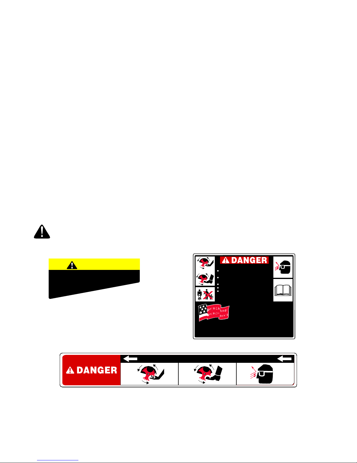
WARNING: YOUR RESPONSIBILITY
Restrict the use of this power machine to persons who read, understand and follow the warnings
and instructions in this manual and on the machine.
WARNING
TO REDUCE THE RISK OF INJURY,
DO NO T OPERATE WITHOUT
GUARDS IN
PLACE.
S30022
For Customer Assistan ce Call:
1-330-220-4MTD
1-800-800-7310
Have your model number ready when you call
AVOID SERIOUS INJURY OR DEATH
KEEP HANDS AND FEET AWAY F ROM
ROTATING BLADE.
WEAR SAFETY GLASSES. BLAD E MAY
THROW OBJECTS.
KEEP BYSTANDERS AWAY.
READ OPERATOR'S MANUAL.
KEEP SAFETY DEVICES (BLADE CONTROL,
BLADE GUARD, DEBRIS SHIELD, BELT
GUARD, ETC.) IN PLACE AND WO RKING.
PLACE MODEL PLATE HERE
S30279
KEEP AWAY - ROTATING BLADE
Figure 1
4
Page 5
SECTION 2: ASSEMBLING THE EDGER
IMPORTANT:
GASOLINE OR OIL. After setting up the unit, service
engine with gasoline and oil as instructed in the
separate engine manual packed with your unit.
NOTE: Reference to right or left hand side of the edger
is observed from the operating position.
This unit is shipped WITHOUT
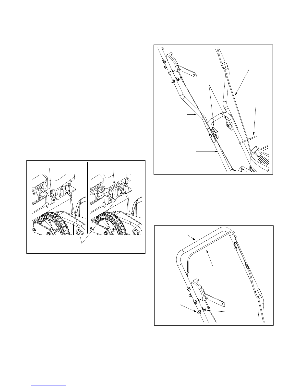
Grounding the Engine’s Spark Plug
• Before beginning assembly, disconnect the spark
plug wire from the spark plug and ground it against
the engine as follows:
Model 534
• Place the rubber boot at the end of the spark plug
wire over an engine head bolt. See Figure 2A.
Model 532
• Place the metal head of the spark plug wire over
the “V” groove cut in the front of the engine shroud.
See Figure 2B.
AB
Head Bolt
“V” Groove
Control Cable
Wing Knobs
Cable Tie
Upper Handle
Lower Handle
Figure 3
Spark Plug Wire
Figure 2
Positioning the Edger Handles
• Remove and discard any packaging cardboard that
may be present between the upper handle and the
lower handle.
• Pivot the upper handle upward until it snaps into
place.
NOTE: Be careful not to pinch or crimp either cable
when lifting the handle.
• Tighten the wing knobs which are located on both
the sides of the lower handle. See Figure 3.
• Pull the cable tie found on the left side of the lower
handle snugly to secure the cable to the handle.
Carefully trim any excess portion of the cable tie
after tightening. See Figure 3.
Attaching the Starter Rope
• Locate the eyebolt found on the right side of the
upper handle.
• Loosen, but do NOT remove, the wing knob which
secures the rope guide to the upper handle. See
Figure 4.
Upper Handle
Blade Control Bail
Rope Guide
Wing Knob
Figure 4
IMPORTANT:
wire is properly grounded as instructed earlier in this
section before proceeding on to the next step. See
Figure 2.
Make certain that the engine’s spark plug
5
Page 6

• Stand behind the unit and hold the blade control
bail against the upper handle and gently pull the
starter rope out of the engine.
WARNING: The edger blade WILL rotate
when the starter rope is pulled.
NOTE: The starter rope will not pull out of the engine
unless the blade control bail (refer to Figure 4) is
depressed against the upper handle.
• Slip the starter rope through the top of the rope
guide.
• Retighten the wing knob which secures the rope
guide to the upper handle.
• Loosen the jam nut found on the depth cable and
again attempt to place the blade depth control lever
in the start position. Continue doing so until the
blade depth control lever fits snugly into the start
position notch.
• Once this position is attained, secure the top of the
cable with a pair of pliers and retighten the jam nut.
Blade Depth
Control Lever
Start Position
Checking The Blade Depth Control
The blade depth control lever has been pre-adjusted at
the factory. Before operating the edger, however, check
the adjustment of the depth cable as follows:
• Move the blade depth control lever to the lowest
position then back to the start position on the
handle. See Figure 5.
• If the blade depth control can be easily placed in
the start position, no adjustment is necessary. If the
blade depth control will NOT go to the start position,
continue as follows:
SECTION 3: KNOW THE EDGER
Throttle Control
The throttle control lever is located on the front of the
engine. It can be adjusted to regulate the engine speed.
Never attempt to adjust the throttle while
the engine is running. Stop the engine by
releasing the blade control bail before
making any throttle adjustment.
NOTE: Refer to the separate engine manual packed
with your edger for a detailed description of all enginerelated controls and components.
Blade Control Bail
Located on the upper handle, the blade control bail
must be depressed against the upper handle in order to
operate the unit. Releasing the blade control bail stops
the engine and the edger blade.
Blade Depth Control Lever
The blade depth control lever is located on the right
side of the upper handle. It is used to control the depth
of the cut. The further forward the blade depth control
lever is moved, the deeper into the soil the edger blade
will cut.
Lowest Position
Jam Nut
Depth Cable
Figure 5
Primer
The primer is used to pump gas into the carburetor and
aid in starting the engine. Use it to start a cold engine,
but do not use it to restart a warm engine after a short
shutdown.
NOTE: Refer to the separate engine manual packed
with your edger for a detailed description of all enginerelated controls and components.
Pull Rope/Recoil Starter
The pull rope/recoil starter is used to start the engine.
Blade Tilt Control
The blade tilt control is located on the rear portion of the
edger. It is used to vary the angle of the edger blade
between one of five positions from beveling to edging to
trenching.
Curb Wheel Control Lever (if so equipped)
The curb wheel control lever, if so equipped, is found on
the rear, right portion of the edger. When placed in an
applicable notch, it aids in stabilizing the edger while
edging grass along a curb.
6
Page 7

Blade Control Bail
Pull Rope /
Recoil Starter
Blade Tilt Control
Curb Wheel Control Lever
(if so equipped)
Figure 6
SECTION 4: OPERATING THE EDGER
WEAR YOUR
SAFETY GLASSES
FORESIGHT IS BETTER
THAN NO SIGHT
The operation of any edger can result
in foreign objects being thrown into
the eyes, which can result in severe
eye damage. Always wear safety
glasses or eye shields. We
recommend wide vision safety mask
for over spectacles or standard
safety glasses
WARNING: Do not lower blade if blade is
over concrete, asphalt, rocks or the like.
The blade can strike the supporting
surface, which could result in personal
injury or property damage.
Blade Depth Control Lever
Throttle Control
Primer
To start the edger’s engine, proceed as follows:
• Attach the spark plug wire to the spark plug. Make
certain the metal cap on the end of the spark plug
wire is fastened securely over the metal tip on the
spark plug.
• Move the blade depth control lever back to the
START position, and place it in the adjacent notch.
Refer to Figure 5.
• Move the throttle control lever on the engine to the
FAST (Rabbit) position. See Figure 7.
Adding Gasoline And Oil
Service the engine with gasoline and oil as instructed in
the separate engine manual packed with your edger.
WARNING: Never fill fuel tank indoors,
with engine running or until the engine has
been allowed to cool for at least two
minutes after running.
Starting The Engine
NOTE: Refer to the separate engine manual packed
with your edger for a detailed description of all enginerelated controls and components.
Figure 7
• Depress the primer bulb three times, pausing two to
three seconds between each push. In cold weather
(below 50°F /19°C), it may be necessary to depress
the primer bulb four or five times.
IMPORTANT:
Using the primer to restart a warm engine
after a short shutdown is usually NOT necessary. Doing
so may result in a “flooded” engine.
• Standing behind the unit, depress the blade control
bail and hold it against the upper handle with your
left hand.
7
Page 8

WARNING: This control mechanism is a
safety device. Never attempt to bypass its
operation.
NOTE: If the engine fails to start after three pulls,
depress the primer an additional two times before
pulling the starter rope again.
• With your right hand, grasp the starter handle and
slowly pull the rope outward until the engine
reaches the start of its compression cycle (the rope
will pull slightly harder at this point).
• After slowly allowing the rope to recoil, pull the rope
with a rapid, continuous, full arm stroke. Keep a firm
grip on starter handle throughout the entire stroke.
• Allow the starter handle to slowly return to the
eyebolt.
SECTION 5: MAKING ADJUSTMENTS
Carburetor Adjustment
Refer to the separate engine manual packed with your
edger for a detailed description of all engine-related
adjustments, controls and components.
Blade Tilt Adjustment
The angle of the edger blade can be adjusted by
placing the blade tilt control lever in one of five positions
from beveling to edging to trenching. See Figure 8.
Stopping The Engine
To stop the edger’s engine, proceed as follows:
• Release the blade control handle.
IMPORTANT:
wire is properly grounded as instructed in SECTION 2:
Assembling The Edger before storing the edger for its
next use. Refer to Figure 2.
Make certain that the engine’s spark plug
WARNING: Rotating cutting blade may
throw objects causing personal injury.
Keep area clear of bystanders and do not
operate without guards in place.
Blade Tilt
Control Lever
Beveling
Edging
Trenching
Figure 8
Beveling
Set the blade tilt control lever (refer to Figure 8) in the
first or second notch to place the edger blade in position
for beveling. See Figure 9.
Beveling Position
Figure 9
Edging
Set the blade tilt control lever (refer to Figure 8) in the
center notch to place the edger blade in a 90° position
for edging. See Figure 10.
90° Edging Position
Figure 10
8
Page 9

Trenching
Set the blade tilt control lever (refer to Figure 8) in the
fourth or fifth notch to place the edger blade in position
for trenching. See Figure 11.
Curb Wheel Control Lever
(Normal Operating Position)
Trenching Position
Figure 11
Edging Along A Curb (models so equipped)
NOTE: Edger features vary by model. All edger models
do NOT come equipped to edge along a curb nor is
there a curb wheel kit available to modify your edger if it
was not purchased equipped to do so.
To edge along a curb, lower the right rear wheel by
moving the curb wheel control lever toward the rear of
the unit, pivoting the wheel to the desired depth and
releasing the lever. See Figure 12.
When edging along a curb, the edger will ride on the
two rear wheels and the support roller located beneath
the edger base, behind the blade. The wheel at the
front of the edger is NOT used when edging along a
curb. See Figure 13.
Figure 12
Curb Wheel Control Lever
(Lowered Position)
Figure 13
9
Page 10

SECTION 6: MAINTAINING & SERVICING THE EDGER
WARNING: Disconnect the spark plug wire
and ground against the engine before
performing any adjustment, repairs or
maintenance.
Replacing the Edger Blade
WARNING: The edger blade is sharp. Wear
leather work gloves to protect your hands
when working around the edger blade.
• Use two wrenches (one wrench to prevent the hex
bolt head from spinning and the other to unthread
the hex lock nut) to remove the edger blade. See
Figure 14.
Hex Bolt Head
Figure 14
• Remove and discard the edger blade but retain the
bell washer and hex lock nut.
• Install the replacement edger blade (part no. 781-
0080), and the bell washer (cupped side facing
inward, against the blade) before securing with the
hex lock nut removed earlier.
IMPORTANT:
lock nut to between 37 foot-lbs. and 50 foot- lbs.
Use a torque wrench to tighten the hex
Hex Lock Nut
Replacing the Drive Belt
WARNING: Disconnect the spark plug wire
and ground against the engine before
performing the following steps.
WARNING: The edger blade is sharp. Wear
leather work gloves to protect your hands
when working around the edger blade.
IMPORTANT:
of the drive belt on the blade spindle pulley and the
engine pulley prior to performing the following steps.
• Place the blade adjustment lever in the bevel
position. Refer to Figure 9.
To aid in reassembly, note the orientation
• Remove the belt guard by removing the single selftapping screw which secures it to the blade spindle.
See Figure 15.
Belt Guard
Figure 15
Remove the drive belt from around the blade spindle
pulley as follows:
1. Working in front of the edger, facing the spindle
housing, position the drive belt to the left, slightly off
the upper portion of the spindle pulley.
2. While holding the belt in this position with one hand,
carefully grasp the lower portion of the blade with
your other hand and rotate it away from you,
causing the belt to “roll” off of the pulley.
3. If it hasn’t already freed itself, carefully remove the
drive belt from around the engine pulley. Discard
the belt.
Install the replacement belt (Part No. 754-0343) in the
same configuration that the original belt was routed as
follows:
1. Working in front of the edger, facing the spindle
housing, carefully reach beneath the edger and
loop the drive belt around the engine pulley.
2. Position the opposite end of the drive belt loop
around the lower portion of the spindle pulley,
allowing the remaining portion of the belt to rest to
the left, slightly off the upper portion of the pulley.
3. While holding the belt in this position with one hand,
carefully grasp the lower portion of the blade with
your other hand and rotate it toward you, causing
the belt to “roll” onto the pulley.
IMPORTANT:
seated snugly in both the engine pulley and the blade
spindle pulley.
• Replace the belt guard and self-tapping screw
removed in earlier steps.
Make certain that the “V” side of the belt is
Self-tapping
Screw
10
Page 11

Lubrication
WARNING: Always stop engine and
disconnect spark plug wire before
cleaning, lubricating or doing any kind of
work on edger.
Engine
Refer to the separate engine manual packed with your
edger for detailed instructions of all engine-related
maintenance & lubrication.
Wheels
Lubricate the wheels and bearings at least once a
season with light oil or engine oil. Also if the wheels are
removed for any reason, lubricate the surface of the
axle bolt and the inner surface of the wheel with light oil.
SECTION 7: OFF-SEASON STORAGE
Observe the following when preparing the edger for
long-term storage:
• Clean and lubricate unit thoroughly according to the
lubrication section.
• Refer to the engine manual packed separately with
the edger for engine storage instructions.
• Coat the edger blade with chassis grease to
prevent rusting and corrosion.
Pivot Points
Lubricate the pivot points on the blade control handle,
curb wheel control lever, blade depth control lever and
the blade adjustment lever with light oil at least once a
season.
Cutting Head Bearings
The two ball bearings in the blade spindle housing are
lubricated and sealed at the factory and require no
lubrication. Lubricate all other moving parts with a light
oil.
Spindle Shaft
Lubricate the two bearings and under the compression
spring on the shaft with light oil frequently during the
season. Do NOT allow rust to form in this area.
• Store the edger in a dry, clean area. Do not store
next to any corrosive materials, such as lawn
fertilizer.
• Coat the edger, especially any springs and
bearings with a light oil or silicone spray.
IMPORTANT:
equipment in an poorly ventilated or metal storage
shed, care should be taken to rustproof the equipment.
When storing any type of power
11
Page 12

SECTION 8: TROUBLESHOOTING
Trouble Possible Cause(s) Corrective Action
Engine fails to start Dirty air cleaner
Engine needs to be primed
Fuel tank empty
Stale fuel in gasoline tank
Throttle lever not in FAST
Spark plug wire disconnected.
Spark plug fauled
Engine flooded
Engine runs erratic Spark plug wire loose
Stale fuel in gasoline tank
Vent in gas cap plugged
Water or dirt in fuel system
Dirty air cleaner
Carburetor out of adjustment
Engine overheats Engine oil level low
Air flow restricted
Dirty air filter
Carburetor not adjusted properly
Excessive vibration Edger blade bent or damaged
Blade spindle bent or damaged
Drive belt slips Belt worn or stretched Replace drive belt.
Refer to the engine manual packed with your unit.
Push primer bulb two or three times.
Fill tank with clean, fresh gasoline.
Drain gasoline and refill tank with clean, fresh gasoline.
Move throttle lever to FAST (rabbit) position.
Connect the spark plug wire to the spark plug.
Clean, adjust gap or replace spark plug.
Refer to the engine manual packed with your unit.
Connect and tighten spark plug wire.
Drain gasoline and refill tank with clean, fresh gasoline.
Clear vent of any debris.
Drain fuel tank. Refill with fresh fuel.
Refer to the engine manual packed with your unit.
Refer to the engine manual packed with your unit.
Fill crankcase with proper oil.
Clean grass from around the engine’s cooling fins.
Replace the engine’s air filter.
Refer to the engine manual packed with your unit.
Replace edger blade.
Contact an authorized MTD service dealer.
12
Page 13

SECTION 9: MODELS 532 & 534 PARTS LIST
28
27
26
29
30
6
1
Edger base assembly shown for reference only.
See page 14 for handle & frame parts breakdown.
19 20
8
17
11
15
Spindle Assembly
24
23
16
21
23
25
15
Ref.
No.
1.
2.
3.
4.
5.
6.
7.
8.
9.
10.
11.
12.
13.
14.
15.
7
6
9
5
4
3
2
Part Number Description
732-0862 Compression Spring
710-1627 Hex Cap Screw, 5/8-18 x 5.25
710-0191 Hex Cap Screw, 3/8-24 x 1.25
736-0452 Bell Washer, .396 x 1.14 x .095
736-0320 Flat Washer, .38 x 1.38 x .12
710-1241 Hi-Lo Tap Screw, 1/4-15 x 1.0
731-1930 Rear Rod Holder
756-1150A Flywheel/Pulley Combination
754-0343 V-belt
756-0449 Sheave, .6255 x .6295
731-1929 Front Rod Holder
736-0116 Flat Washer, .635 x .93 x .06
741-0155 Ball Bearing, .62 x 1.38 x .44
731-1939 Belt Guard
710-0642 Self-tapping Screw, 1/4-20 x .75
10
12
Ref.
No.
16.
17.
18.
19.
20.
21.
22.
23.
24.
25.
26.
27.
28.
29.
30.
13
18
13
14
16
15
Part Number Description
736-0142 Flat Washer, .281 x .50 x .063
719-0387A Spindle Bearing Housing w/ Insert
750-1158 Spacer, .628 x .875 x 1.818
731-1942 Blade Guard
781-0740 Blade Guide
750-1163 Spacer, .628 x .875 x .545
712-0318 Jam Nut, 5/18-18
736-0317 Bell Washer, .64 x 1.25 x .18
781-0080 Standard Edger Blade, 9”
712-0413 Nylon Lock Jam Nut, 5/8-18
681-0139 Angle Adjustment Lever Ass’y
715-0121 Spirol Pin, 1/4-20
715-0143 Spirol Spring Pin, 1/4
732-0188A Double Torsion Spring
781-0749 Tilt index Bracket
13
Page 14

Models 532 & 534
27
26
32
15
12
33
40
11
24
6
2
7
19
30
A
24
16
42
6
29
49
14
39
9
24
50
36
3
55
56
42
54
57
47
53
26
28
35
45
A
59
44
45
58
48
38
13
21
21
19
45
5
31
17
46
48
20
50
1
52
25
43
8
18
34
22
11
13
10
37
41
14
Page 15

Handle / Frame Assembly
Ref.
No.
1.
2.
3.
4.
5.
6.
7.
8.
9.
10.
11.
12.
13.
14.
15.
16.
17.
18.
19.
20.
21.
22.
23.
24.
25.
26.
27.
28.
29.
30.
Part Number Description
681-0141 Front Wheel Bracket Assembly
710-0116 Hex Cap Screw, 5/16-18 x 2.0
710-0134 Carriage Screw, 1/4-20 x .625
710-0578 Machine Screw, 1/4-20 x 1.5
710-1007 Sems Screw, 3/8-16 x 1.5
710-1174 Carriage Bolt, 5/16-18 x 2.0
710-1205 Eye Bolt (Rope Guide), 1/4-20
710-3013 Hex Cap Screw, 1/4-20 x .5
710-3180 Hex Cap Screw, 5/16-18 x 1.75
712-0287 Hex Nut, 1/4-20
712-0324 Hex Lock Nut, 1/4-20
712-0429 Hex Lock Nut, 5/16-18
712-3020 Jam Lock Nut, 3/8-16
720-0241 Wing Knob, 5/16-18
720-0279 Wing Knob, 1/4-20
726-0240 Cable Tie
731-1931 Block Bushing, .515 x .62
731-1935 Discharge Deflector Shield
732-0369 Compression Spring, .55 x 1.37
732-0867 LH Torsion Spring, .655
736-0258 Flat Washer, .385 x 1.0 x .135
736-0329 Lock Washer, 1/4
736-0342 Flat Washer, .283 x .75 x .030
736-0451 Saddle Washer, .320 x .93
738-0481A Shoulder Screw, 3/8-16, .5 x 2.62
746-1094 Depth Index Cable, 44.5”
747-0976A Blade Control Bail
747-0993 Cable Roller Rod
749-1078 Lower Handle
749-1225 Upper Handle
Ref.
No.
31.
32.
33.
34.
35.
36.
37.
38.
39.
40.
41.
42.
43.
44.
45.
46.
47.
48.
49.
50.
51.
52.
53.
54.
55.
56.
57.
58.
59.
Part Number Description
756-0625 Cable Roller
781-0741 Depth Index Bracket
781-0742 Depth Index Lever
781-0746 Discharge Deflector Keeper
781-0747 Depth Cable Keeper
631-0079A Edger Base Assembly
750-1179 Sleeve Spacer, .520 x .860
781-0783 Curb Wheel Adjuster Plate
781-0781 Curb Wheel Back Plate
746-1098 Control Cable w/ Clip, 31.75”
734-1988 Bar Tread Wheel, 7 x 1.8
734-1987 Bar Tread Wheel, 8 x 1.8
681-0140 Curb Wheel Support Bracket
710-1017 Truss Screw, 1/4-14 x .625
710-1241 Hi-Lo Tap Screw, 1/4-15 x 1.0
711-1171 Ferrule, 5/16-24 s .312
711-1278 Curb Axle
714-0104 Internal Cotter Pin
720-0312 Height Adjuster Grip, 2.5”
726-0100 Push Cap, 3/8
726-0299 Push Cap, 1/2
731-1932 Curb Support Roller
732-0982 Height Adjuster Spring Lever
736-0105 Bell Washer, .401 x .870 x .063
736-0326 Flat Washer, .510 x 1.0 x .125
738-0102 Shoulder Screw, 3/8-16, .49 x 1.4
738-0507B Shoulder Screw, .50 x .434
747-0991 Link Rod, 5/16-24
781-0744 Curb Wheel Pivot Arm
15
Page 16

MANUFACTURER’S LIMITED WARRANTY FOR:
The limited warranty set forth below is given by MTD
PRODUCTS INC (“MTD”) with respect to new merchandise
purchased and used in the United States, its possessions
and territories.
MTD warrants this product against defects in material and
workmanship for a period of two (2) years commencing on
the date of original purchase and will, at its option, repair or
replace, free of charge, any part found to be defective in
material or workmanship. This limited warranty shall only
apply if this product has been operated and maintained in
accordance with the Operator’s Manual furnished with the
product, and has not been subject to misuse, abuse, commercial use, neglect, accident, improper maintenance,
alteration, vandalism, theft, fire, water or damage because
of other peril or natural disaster. Damage resulting from the
installation or use of any accessory or attachment not
approved by MTD Products Inc. for use with the product(s)
covered by this manual will void your warranty as to any
resulting damages.
Normal wear parts or components thereof are subject to
separate terms as follows: All normal wear part or component failures will be covered on the product for a period of
90 days regardless of cause. After 90 days, but within the
two year period, normal wear part failures will be covered
ONLY IF caused by defects in material or workmanship of
OTHER component parts. Normal wear parts and components include, but are not limited to, belts, blades, blade
adapters, grass bags, rider deck wheels, seats, snow
thrower skid shoes, shave plates and tires. Batteries are
covered by a 90-day limited replacement warranty.
HOW TO OBTAIN SERVICE: Warranty service is available,
WITH PROOF OF PURCHASE THROUGH YOUR LOCAL
AUTHORIZED SERVICE DEALER. To locate the dealer in
your area, please check for a listing in the Yellow Pages or
contact the Customer Service Department of MTD PRODUCTS INC by calling 1-800-800-7310 or writing to P.O. Box
368022, Cleveland, Ohio 44136-9722.
This limited warranty does not provide coverage in the
following cases:
a. The engine or component parts thereof. These items
carry a separate manufacturer’s warranty. Please refer
to the applicable manufacturer’s warranty on these
items.
b. Log splitter pumps, valves and cylinders have a sepa-
rate one year warranty.
c. Routine maintenance items such as lubricants, filters,
blade sharpening and tune-ups, or adjustments such
as brake adjustments, clutch adjustments or deck
adjustments; and normal deterioration of the exterior
finish due to use or exposure.
d. MTD does not extend any warranty for products sold
or exported outside of the United States of America,
its possessions and territories, except those sold
through MTD’s authorized channels of export distribu-
tion.
No implied warranty, including any implied warranty of
merchantability or fitness for a particular purpose,
applies after the applicable period of express written
warranty above as to the parts as identified. No other
express warranty or guaranty, whether written or oral,
except as mentioned above, given by any person or
entity, including a dealer or retailer, with respect to any
product shall bind MTD. During the period of the Warranty, the exclusive remedy is repair or replacement of
the product as set forth above. (Some states do not
allow limitations on how long an implied warranty lasts, so
the above limitation may not apply to you.)
The provisions as set forth in this Warranty provide the
sole and exclusive remedy arising from the sales. MTD
shall not be liable for incidental or consequential loss
or damages including, without limitation, expenses
incurred for substitute or replacement lawn care services, for transportation or for related expenses, or for
rental expenses to temporarily replace a warranted
product. (Some states do not allow the exclusion or limita-
tion of incidental or consequential damages, so the above
exclusion or limitation may not apply to you.)
In no event shall recovery of any kind be greater than the
amount of the purchase price of the product sold. Alteration
of the safety features of the product shall void this Warranty. You assume the risk and liability for loss, damage, or
injury to you and your property and/or to others and their
property arising out of the use or misuse or inability to use
the product.
This limited warranty shall not extend to anyone other than
the original purchaser, original lessee or the person for
whom it was purchased as a gift.
How State Law Relates to this Warranty: This limited
warranty gives you specific legal rights, and you may also
have other rights which vary from state to state.
 Loading...