

Page 1

OPERATOR’S MANUAL
REAR TINE
TILLER
MODEL
450 Series
IMPORTANT: READ
SAFETY RULES AND
INSTRUCTIONS CAREFULLY
MTD PRODUCTS LTD. P.O. BOX 1386 KITCHENER, ON N2G 4J1
PRINTED IN THE U.S.A.
772C0731
(10/04)
Page 2

TABLE OF CONTENTS
Content Page
Customer Support 2
Important Safe Operation Practices 3
Loose Parts 5
Assembly 6
Controls 8
Operation 9
How To Use Your Tiller 10
Content Page
Adjustments 11
Lubrication 11
Maintenance 11
Off-Season Storage 12
Trouble Shooting Guide 13
Parts Lists/Pièces détachées 14
Warranty 20
FINDING MODEL NUMBER
This Operator’s Manual is an important part of your new equipment. It will help you assemble, prepare and maintain the unit for
best performance. Please read and understand what it says.
Before you start assembling your new equipment, please locate the model plate on the equipment and copy the
information from it in the space provided below. A sample model plate is also given below. You can locate the model
plate by standing at the operating position and looking down at the rear of the deck . This information will be
necessary to use the manufacturer’s web site and/or help from the Customer Support Department or an authorized
service dealer.
This is where your model number will be.
Model Number
Numéro de modèle
XXXXXXXXXX
Serial Number
Numéro de série
XXXXXXXXXXX
This is where your serial number will be.
www.mtdcanada.com
MTD PRODUCTS LIMITED
KITCHENER, ON N2G 4J1
1-800-668-1238
Copy the model number here:
Copy the serial number here:
ENGINE INFORMATION
The engine manufacturer is responsible for all engine-related issues with regards to performance, power-rating, specifications,
warranty and service. Please refer to the engine manufacturer’s Owner’s/Operator’s Manual packed separately with your unit for
more information.
CALLING CUSTOMER SUPPORT
Please do NOT return the unit to the retailer from which it was purchased, without first contacting Customer Support.
If you have difficulty assembling this product or have any questions regarding the controls, operation or maintenance
of this unit, please call a Customer Support Representataive.
For US Customers: 1- (330) 220-4MTD (4683) or 1- (800)-800-7310
For Canadian Customers: 1-800-668-1238
Please have your unit’s model number and serial number ready when you call. See previous section to locate this information.
You will be asked to enter the serial number in order to process your call.
HOW TO OBTAIN SERVICE
Service is available, WITH PROOF OF PURCHASE, through your local authorized service dealer. To locate the
dealer in your area;
In the U.S.A.
: Check your Yellow Pages, or contact customer support listed about MTD LLC at P.O. Box 361131,
Cleveland, Ohio 44136-0019, or call 1-800-800-7310 or 1-330-220-4683 or log on to our Web site at
www.mtdproducts.com.
In Canada
: Contact MTD Products Limited, Kitchener, ON N2G 4J1, or call 1-800-668-1238 or log on to our Web
site at www.mtdcanada.com.
2
Page 3

SECTION 1: IMPORTANT SAFE OPERATION PRACTICES
WARNING: This symbol points out important safety instructions which, if not followed, could endanger
the personal safety and/or property of yourself and others. Read and follow all instructions in this manual
before attempting to operate your tiller. Failure to comply with these instructions may result in personal
injury. when you see this symbol— HEED ITS WARNING
DANGER: Your tiller was built to be operated according to the rules for safe operation in this manual.
As with any type of power equipment, carelessness or error on the part of the operator can result in
serious injury. This tiller is capable of amputating hands and feet. Failure to observe the following safety
instructions could result in serious injury or death.
TRAINING
1. Read, understand, and follow all instructions on the machine and in the manual(s) before attempting to assemble and operate. Keep this manual in a safe place for future and regular reference and for ordering replacement parts.
2. Be familiar with all controls and their proper
operation. Know how to stop the machine and
disengage them quickly.
3. Never allow children under 14 years old to operate
this machine. Children 14 years old and over should
read and understand the operation instructions and
safety rules in this manual and should be trained
and supervised by a parent.
4. Never allow adults to operate this machine without
proper instruction.
5. Keep bystanders, helpers, children and pets at
least 75 feet from the machine while it is in
operation. Stop machine if anyone enters the area.
PREPARATION
1. Thoroughly inspect the area where the equipment is to be used. Remove all stones, sticks, wire, and other foreign objects which could be tripped over and cause personal injury.
2. Wear sturdy, rough-soled work shoes and closefitting slacks and shirts. Loose fitting clothes and
jewelry can be caught in movable parts. Never
operate this machine in bare feet or sandals.
3. Disengage clutch levers and shift (if provided) lever into neutral ("N") before starting the engine.
4. Never leave this machine unattended with the engine running.
5. Never attempt to make any adjustments while the engine is running, except where specifically recommended in the operator’s manual.
6. To avoid personal injury or property damage use
extreme care in handling gasoline. Gasoline is
extremely flammable and the vapors are
explosive. Serious personal injury can occur when
gasoline is spilled on yourself or your clothes
which can ignite. Wash your skin and change
clothes immediately.
7. Use only an approved gasoline container.
8. Extinguish all cigarettes, cigars, pipes and other
9. Never fuel machine indoors.
10. Never remove gas cap or add fuel while the
11. Allow engine to cool at least two minutes before
12. Never over fill fuel tank. Fill tank to no more than
13. Replace gasoline cap and tighten securely.
14. If gasoline is spilled, wipe it off the engine and
15. Never store the machine or fuel container inside
16. Allow a machine to cool at least 5 minutes before
OPERATION
1. Do not put hands or feet near rotating parts.
2. Do not operate the machine while under the
3. Never operate this machine without good visibility
4. Keep bystanders, helpers, children and pets at
5. Be careful when tilling in hard ground. The tines
6. Exercise extreme caution when operating on or
7. Never operate the machine at high transport
8. Exercise caution to avoid slipping or falling.
.
sources of ignition.
engine is hot or running.
refueling.
½ inch below bottom of filler neck to allow space
for fuel expansion.
equipment. Move unit to another area. Wait 5
minutes before starting the engine.
where there is an open flame, spark or pilot light
as on a water heater, space heater, furnace,
clothes dryer or other gas appliances.
storing.
Contact with the rotating parts can amputate
hands and feet.
influence of alcohol or drugs.
or light. Always be sure of your footing and keep a
firm hold on the handles.
least 75 feet from the machine while it is in
operation. Stop machine if anyone enters the area.
may catch in the ground and propel the tiller
forward. If this occurs, let go of the handle bars and
do not restrain the machine.
crossing gravel surfaces. Stay alert for hidden
hazards or traffic. Do not carry passengers.
speeds on hard or slippery surfaces.
3
Page 4
9. Look down and behind and use care when in reverse or pulling machine towards you.
10. Start the engine according to the instructions found in this manual and keep feet well away from the tines at all times.
11. After striking a foreign object, stop the engine, disconnect the spark plug wire(s) and ground against the engine. Thoroughly inspect the machine for any damage. Repair the damage before starting and operating.
12. Disengage all clutch levers and stop the engine before you leave the operating position (behind the handles). Wait until the tines come to a complete stop before unclogging the tines, making any adjustments, or inspections.
13. Never run an engine indoors or in a poorly ventilated area. Engine exhaust contains carbon monoxide, an odorless, and deadly gas.
14. Muffler and engine become hot and can cause a burn. Do not touch.
15. Use caution when tilling near fences, buildings and underground utilities. Rotating tines can cause property damage or personal injury.
16. Do not overload machine capacity by attempting to till soil too deep at too fast of a rate.
17. If the machine should start making unusual noise or vibration, stop the engine, disconnect the spark plug wire and ground it against the engine. Inspect thoroughly for damage. Repair any damage before starting and operating.
18. Keep all shields, guards and safety devices in place and operating properly.
19. Never pick up or carry machine while the engine is running.
20. Use only accessories and attachments approved for this machine by the machine manufacturer. Failure to do so, can result in serious injury.
21. If situations occur which are not covered in this manual, use care and good judgment. Contact your authorized dealer for assistance.
MAINTENANCE & STORAGE
1. Never tamper with safety devices. Check their proper operation regularly.
2. Check bolts and screws for proper tightness at frequent intervals to keep the machine in safe working condition. Also, visually inspect machine for any damage.
3. Before cleaning, repairing, or inspecting, make certain the tine(s) and all moving parts have stopped. Disconnect the spark plug wire and ground against the engine to prevent unintended starting.
4. Do not change the engine governor settings or over-speed the engine. The governor controls the maximum safe operating speed of the engine.
5. Maintain or replace safety and instruction labels, as necessary.
6. Follow this manual for safe loading, unloading, transporting, and storage of this machine.
7. Never store the machine or fuel container inside where there is an open flame, spark or pilot light as on a water heater, space heater, furnace, clothes dryer or other gas appliances.
8. Always refer to the operator’s manual for proper instructions on off-season storage.
9. If the fuel tank has to be drained, do this outdoors.
10. Observe proper disposal laws and regulations for gas, oil, etc. to protect the environment.
WARNING — YOUR RESPONSIBILITY: Restrict the use of this power machine to persons who read,
understand and follow the warnings and instructions in this manual and on the machine.
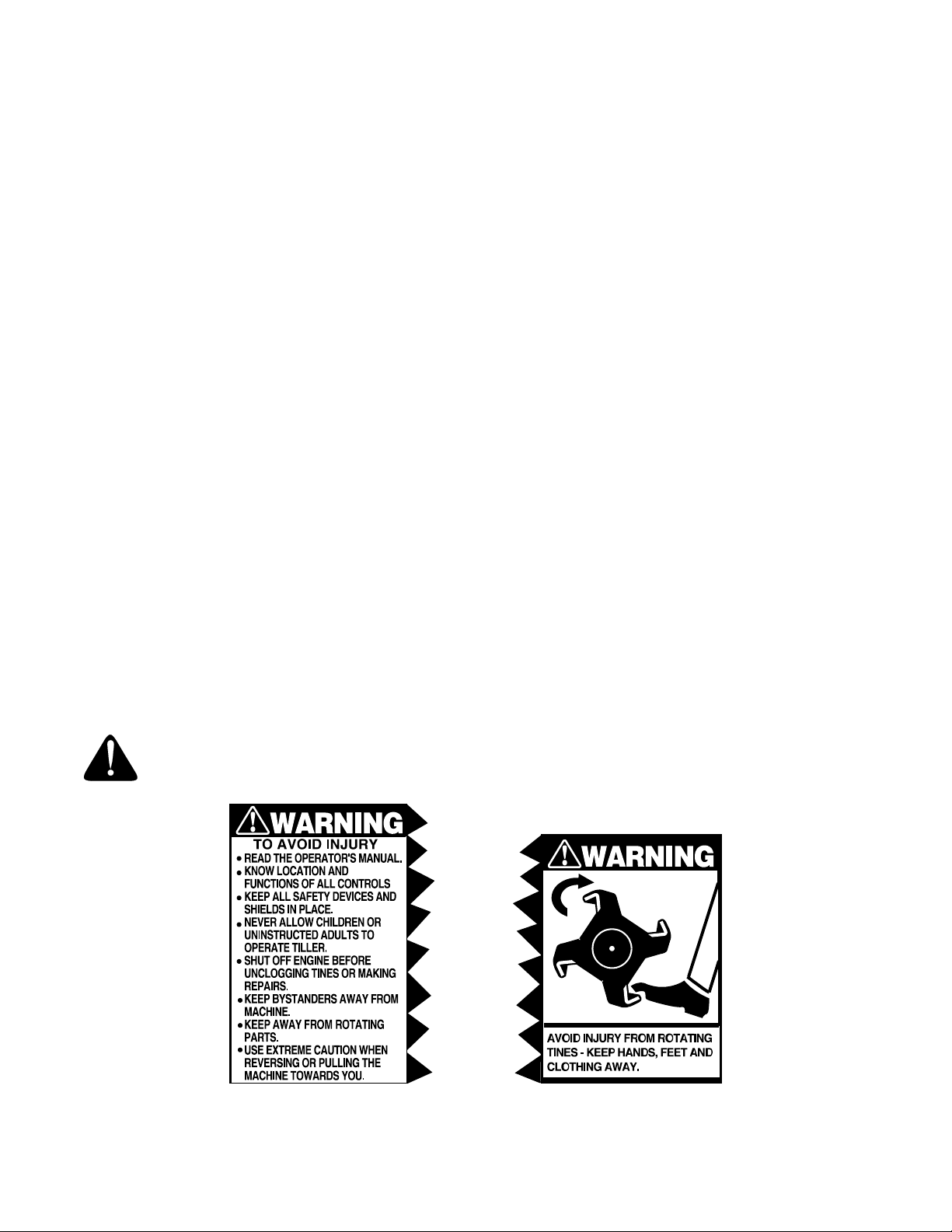
Figure 1 Safety labels found on your unit
4
Page 5
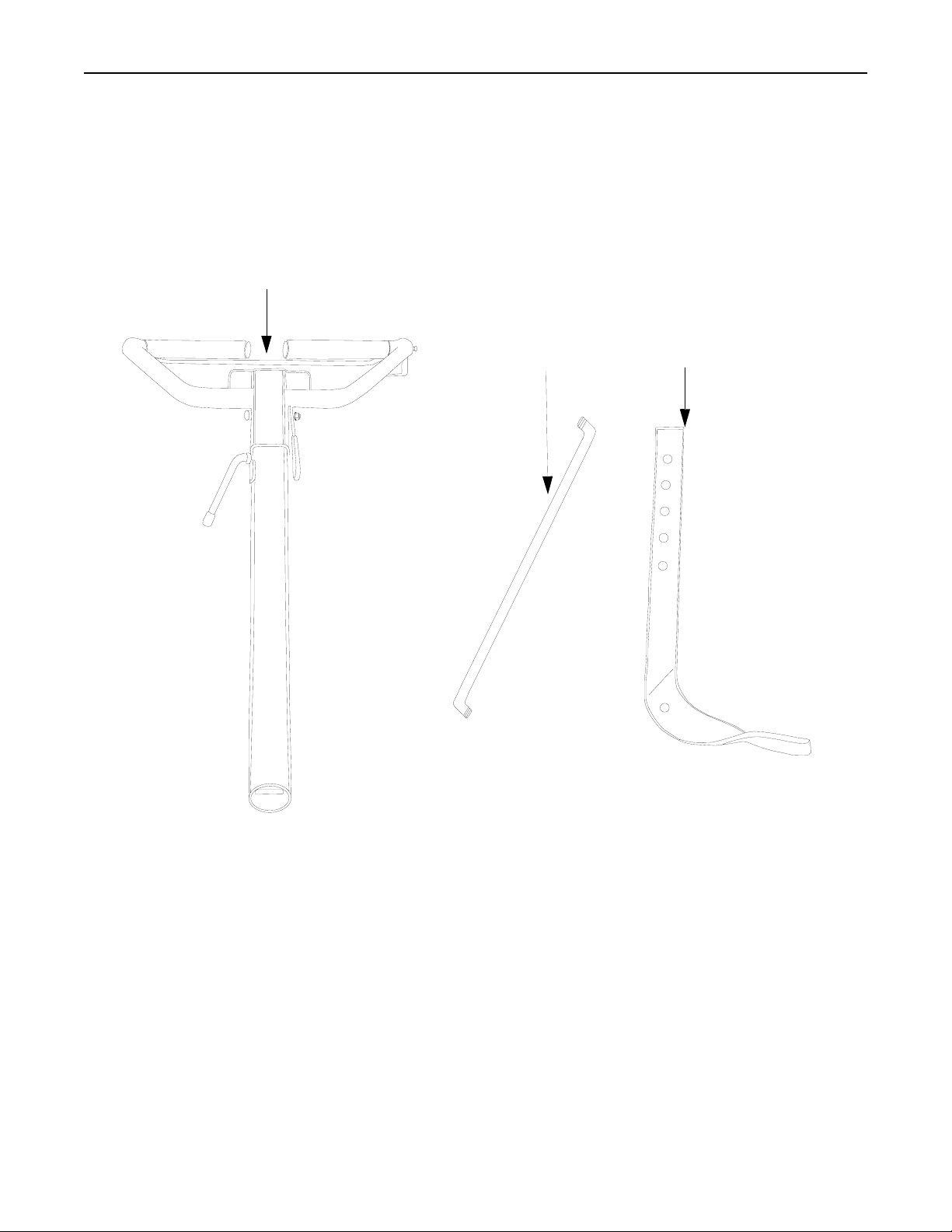
SECTION 2: LOOSE PARTS
Handle
Assembly
Control
Rod
Depth
Stake
Assembly
NOTE: All hardware needed for assembly is attached to the loose parts or the tiller.
NOTE: Cable tie not shown.
5
Page 6

SECTION 3: ASSEMBLY INSTRUCTIONS
IMPORTANT: This unit is shipped WITHOUT
GASOLINE or OIL. After assembly, see separate
engine manual for proper fuel and engine oil
recommendations.
NOTE: Left and right is determined from the
operator’s position, standing behind the tiller.
TOOLS REQUIRED FOR ASSEMBLY
Adjustable Wrenches
Pair of Pliers
Screw Driver
TO REMOVE UNIT FROM CARTON
1. Remove staples, break glue on top flaps, or cut tape at carton end and peel along top flap to open carton.
2. Remove loose parts included with unit (i.e., operator’s manual, etc.).
3. Cut corners and lay carton down flat.
4. Remove packing material.
5. Roll or slide unit out of carton. Check carton thoroughly for loose parts.
6. Extend control cable and lay on the floor. Be careful not to bend or kink control cable.
Hex Bolt
Flat Washer
T-Knob
Clevis Pin
Hairpin Clip
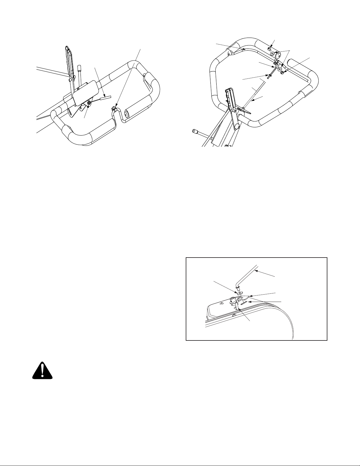
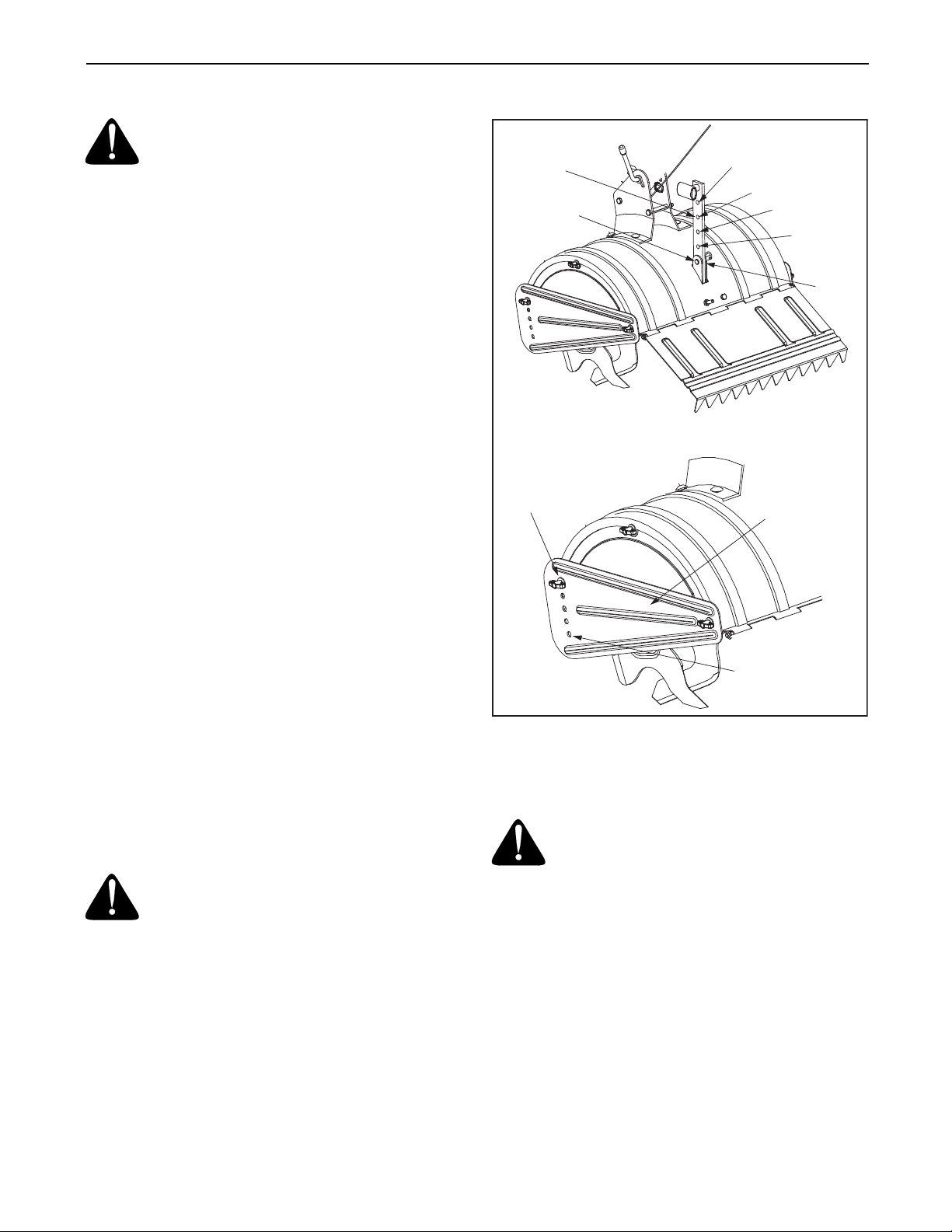
ATTACHING DEPTH STAKE ASSEMBLY
1. Tip the tiller forward so it rests on front counterweight.
2. Raise the tine shield hinge flap assembly. Remove "T" knob, flat washer and hex bolt from depth stake. Insert the depth stake assembly in front of spacer (under the tine shield) and up through the tine shield assembly as shown in Figure 1.
3. Insert clevis pin through the tine shield and the second hole from top of the depth stake. Secure with hairpin clip.
4. Insert hex bolt into the top hole of the depth stake assembly. Place flat washer on hex bolt and thread “T” knob onto the hex bolt. See Figure 1. Tighten securely.
5. Tip the tiller back down so it rests on the depth stake (transport position).
ATTACHING THE HANDLE ASSEMBLY
Remove
Handle
Assembly
Handle
Bracket
Rear Tine
Shield
Depth Stake
WARNING: Disconnect the spark plug
wire and ground against the engine to
prevent unintended starting.
Figure 1
Figure 2
1. Remove top two bolts and flange lock nuts from handle mounting brackets as shown in Figure 2. Do not remove the bottom bolt and nut.
2. Place handle assembly in position between the handle mounting brackets. See Figure 2.
3. Line up holes in handle with holes in handle mounting brackets. Secure with hardware removed in step 1.
6
Page 7
Slot Head Screw,
Nut, Flat Washers
Internally Threaded
Tube
Clutch
Bail
Threaded
Eyebolt
Slot Head Screw
Flat Washers
1/4”
Nut
Plastic Fitting
Figure 3
ATTACHING THE CLUTCH CABLE
Attach the clutch cable to the handle as follows (be
careful not to kink the cable).
1. Remove threaded eyebolt and nut from the end of the cable.
2. Route the clutch cable to the right side of the handle mounting brackets and underneath the handle.
3. Push the cable through the hole in the center of the handle and snap in the plastic fitting. See Figure 3.
4. Remove slot head screw, nut and two flat washers from the clutch bail.
5. Fasten the threaded eyebolt onto bail as shown in Figure 4. The parts go together from top to bottom as follows: Slot Head Screw, Flat Washer, Clip, Eyebolt, Flat Washer and 1/4” Nut.
6. Thread eyebolt and #10 nut, removed in step 1, into the internally threaded tube at the end of the cable. Thread engagement should be about 3/4”. Tighten nut against tube at end of cable. See Figure 4.
#10
Nut
”
4
/
3
Internally
Threaded
Tube
Figure 4
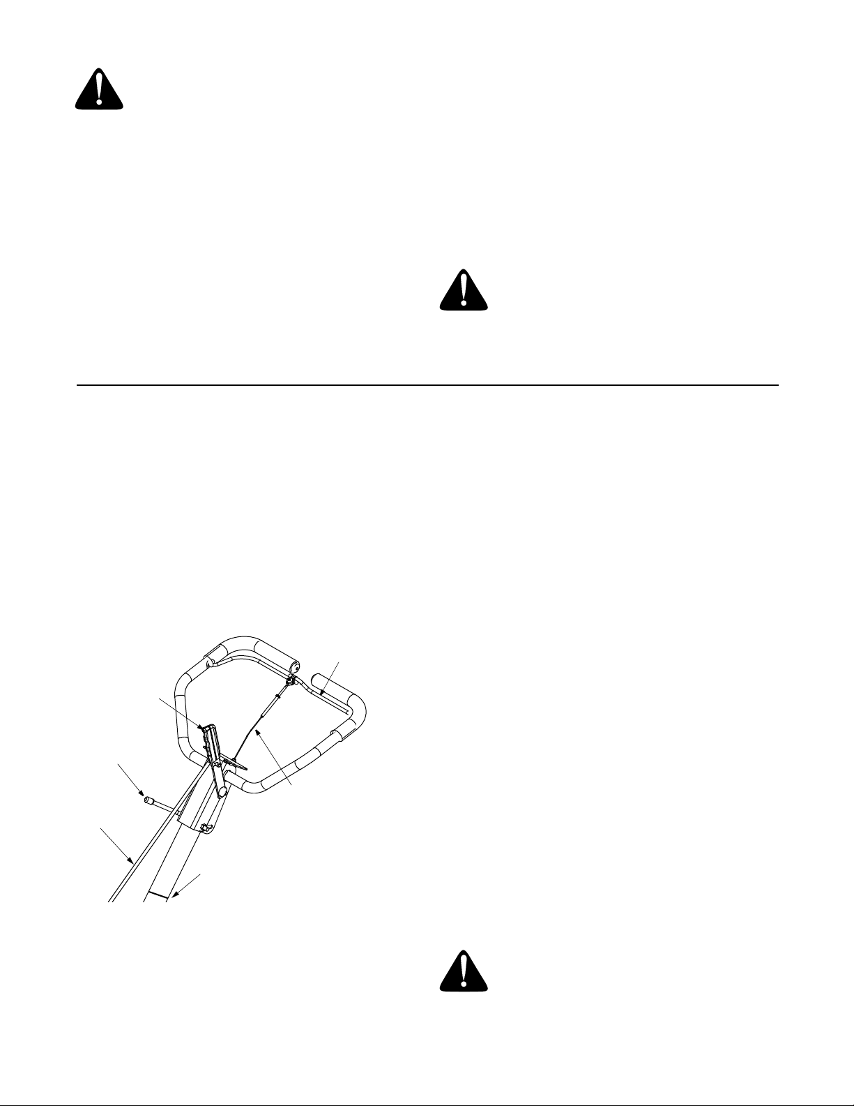
ATTACHING THE CONTROL ROD
• Make sure the handle assembly is in the highest
position.
• Remove hairpin clips from control rod, (rubber
washers to remain on control rod).
• Insert the shorter, (angled), end of the control rod
through the indicator bracket on the shift cover and
secure with hairpin clip that was removed in step 1.
See Figure 5.
• Insert the longer end of the control rod through the
hole in the gear selector handle and secure with
hairpin clip.See Figure 6.
Rubber
Washer
Idler Pulley Rod
Control Rod
Indicator Bracket
Hairpin Clip
NOTE: Do not overtighten control wire. Too much
tension may cause it to break.
WARNING:
clutch cable adjustment before operating
the tiller.
Be certain to check the
Figure 5
CHECKING THE CLUTCH ADJUSTMENT
IMPORTANT:
gasoline before checking this adjustment. Refer to the
separate engine manual packed with your tiller for
proper fuel and engine oil recommendations.
Position the tiller so the front counterweight is against
a solid object, such as a wall. With the gear selection
lever in NEUTRAL, start the engine. Refer to the
separate engine manual.
Standing on the right side of the tiller, examine the belt
(inside the belt cover). It should not be turning.
7
Service the engine with oil and
Page 8
WARNING: Do not put fingers under the
belt cover.
If the belt turns without bail engaged, adjust by
unthreading the internally threaded tube at the end of
the cable a few turns clockwise (when standing in
operator’s position), and then retighten the nut against
the tube.
Now move the shift lever to FORWARD (Wheels
Forward) position. Carefully engage the clutch by lifting
the clutch control bail against the handle. The wheels
should spin.
If the wheels do not spin with the unit in forward,
adjust by unthreading the tube at the end of the cable a
few turns counter-clockwise, (when standing in
operator’s position), and then retighten the nut against
the tube.
Recheck both adjustments, and readjust as necessary.
SECTION 4: CONTROLS
NOTE: A secondary cable adjustment is available if
you reach the point that additional adjustment is
needed. Remove the belt cover and move the hex nuts
at the other end of the cable towards the end of the
casing. Then readjust the hex nuts at the handle.
TIRE PRESSURE
The tires on your unit may be over-inflated for shipping
purposes. Reduce the tire pressure before operating
the unit. Recommended operating tire pressure is
approximately 20 p.s.i. (check sidewall of tire for tire
manufacturer’s recommended pressure).
WARNING: Maximum tire pressure
under any circumstances is 30 p.s.i. Equal
tire pressure should be maintained on
both tires.
THROTTLE CONTROL
The throttle control lever is located on the engine. It
controls the engine speed and stops the engine. See
Engine manual for further information.
CHOKE LEVER (if equipped)
The choke lever is located to the left of the throttle. It is
used to enrich the fuel mixture in the carburetor when
starting a cold engine. See Engine manual for further
information.
Clutch
Gear Selection Handle
Height
Adjustment
Lever
Control
Rod
Clutch
Cable
Cable Tie
Figure 6
Control
Bail
below). Pull or push the handle so that the indicator on
top of shift cover points to the operating mode desired.
See Figure 6.
NEUTRAL—Transmission is in neutral.
REVERSE—Reverse wheel drive.
FORWARD Modes:
Wheels Forward— Forward wheel drive only.
Tines Reverse— Forward wheel drive and reverse
tine drive.
Tines Forward— Forward wheel and tine drive.
IMPORTANT: Use the reverse tine drive when
tilling virgin ground, sod, or hard soil. Use the forward
tine drive when cultivating or tilling soft ground.
NOTE: If difficulty is encountered in moving the gear
selection handle, move the tiller forward or backward
slightly to allow the gears to synchronize.
• To shift into forward or reverse wheel drive,
move tiller forward slightly then backward to
allow the gears to synchronize.
• To shift into forward wheels and tine drive, push
forward slightly on the gear selection handle and
slowly engage the clutch control allowing the
gears to synchronize.
• To stop forward movement and tine drive,
release the clutch control. Do not shift gears
with the clutch control engaged except when
engaging the tines.
GEAR SELECTION HANDLE
The gear selection handle is located in the center of
the handle on the tiller. It is used to select NEUTRAL,
REVERSE, or one of the FORWARD modes (see
WARNING: Make certain unit is in
NEUTRAL when starting the engine.
8
Page 9

DEPTH STAKE
The depth bar controls the tilling depth. Refer to
SECTION 6: HOW TO USE YOUR TILLER on page
10.
ENGINE CONTROLS
See the separate engine manual for additional
information and functions of the engine controls.
PRIMER BUTTON (if equipped)
The primer button is located behind the air cleaner. It
is used to enrich the fuel mixture in the carburetor
when starting a cold engine.
SECTION 5: OPERATION
HANDLE ADJUSTMENT
The handle may be adjusted to be raised or lowered in
line with the tiller. To adjust the handle position loosen
the handle height adjustment crank a few turns. Pivot
handle up or down to desired position. Tighten crank.
See Figure 6.
CLUTCH CONTROL BAIL
The clutch control bail is located below the handle.
See Figure 6. Lifting the clutch control bail against the
handle engages the wheel and tine drive mechanisms.
NOTE: Never engage clutch lever while shifting.
NOTE: Engine is shipped WITHOUT oil.
WARNING: Read, understand, and
follow all instructions and warnings on
the machine and in this manual before
operating.
BEFORE STARTING
Service engine with gasoline and oil as instructed in
the separate engine manual packed with your tiller.
Read instructions carefully.
WARNING: Use extreme care when
handling gasoline. Gasoline is extremely
flammable and the vapors are explosive.
Never fuel machine indoors or while the
engine is hot or running.
TO START ENGINE
NOTE: When pushing the unit with the engine off,
you will hear a ratcheting sound (gear noise) which is
normal.
WARNING: Be Sure No One Is Standing
In Front Of The Tiller While The Engine Is
Running Or Being Started.
1. Place gear selection lever in NEUTRAL.
2. Place the throttle control lever in the FAST (rabbit) position. Place the engine speed control in the START position.
3. Move choke lever to CHOKE position or if equipped, push primer two (2) or three (3) times. Wait about two (2) seconds between each push.
4. Stand at side of tiller. Grasp the starter handle and pull out slowly, until it pulls slightly harder. Let rope rewind slowly.
5. Pull starter handle rapidly. Do not allow handle to snap back. Allow it to rewind slowly while keeping a firm hold on the starter handle.
6. Repeat steps 3 and 4 until engine starts.
7. As engine warms up and begins to operate evenly, move choke lever gradually to RUN position. If engine falters, return to choke position, then slowly move to RUN position.
NOTE: Refer to engine manual for additional engine
information.
NOTE: After starting engine and prior to using the
tiller, be certain to check the clutch adjustment as
described in “Checking the Clutch Adjustment” section
of Assembly Instructions.
TO STOP ENGINE
1. Move throttle control to the STOP position.
2. Disconnect spark plug wire and ground to prevent
accidentally starting while equipment is
unattended.
NOTE: After the first ten hours of operation, recheck
the clutch adjustment. Refer to “Checking the Clutch
Adjustment” section of the Assembly Instructions.
NOTE: A warm engine may not require choking.
9
Page 10
SECTION 6: HOW TO USE YOUR TILLER
WARNING: Be certain the spark plug
wire is disconnected and grounded
against the engine when performing any
adjustments.
Tilling depth is controlled by the depth stake which can
be adjusted to five different settings. See Figure 7.
Adjust the side shields as shown in Figure 7, as you
adjust the depth stake. Be certain spark plug wire is
disconnected and grounded against the engine.
1. When using the tiller for the first time, use the second adjustment hole from the top (1" of tilling depth). See Figure 7.
2. When breaking up sod and for shallow cultivation,
use the setting which gives 1" of tilling depth
(second hole from the top). Place the side shields
in their lowest position. For further depth, raise the
depth stake and side shields and make one or two
more passes over the area.
3. When tilling loose soil, depth stake may be raised to its highest position (use bottom adjustment hole) to give the deepest tilling depth. Raise the side shields to their highest position.
4. To transport tiller, lower the depth stake (use top adjustment hole).
To adjust the depth stake, remove the clevis pin and
hairpin clip. See Figure 7. Move the depth stake to the
desired setting and secure with the clevis pin and
hairpin clip.
To adjust the side shields, remove the wing nuts. See
Figure 7. Place side shield in position desired. Replace
wing nuts and tighten securely.
TO OPERATE THE TILLER:
1. Select the depth stake setting.
2. Start engine as instructed on page 9.
3. Move gear selection handle to one of the forward modes or reverse.
WARNING: Do not move the gear
selection handle with the wheels or tines
engaged. Make certain the unit is stopped
completely before changing the gear
selection.
To transport tiller, do not engage the tines. Select the
wheel drive only.
For best results, it is recommended the garden be tilled
twice (lengthwise, then widthwise) to pulverize the soil.
Use This
Position
First Time
Clevis Pin
Use This Hole For
Lowest (shallowest)
Position
WARNING: Do not push down on the
handles so that the wheels are lifted off
the ground while using the reverse tine
drive, or the tiller could move backward
and cause personal injury.
Figure 7
Transport Position
1”
3”
5”
7”
Side Shields
Use This Hole For
Highest (Deepest)
Position
IMPORTANT: Use the reverse tine drive when
tilling virgin ground, sod or hard soil. Use the forward
tine drive when cultivating or tilling soft ground.
4. Squeeze the clutch control bail against the handle to engage the wheels and tines.
NOTE: Make certain the gear selection indicator is
correctly positioned before engaging the clutch handle.
If it is between gears, the engine will stall.
10
Page 11
SECTION 7: ADJUSTMENTS
WARNING: Never attempt to make any
adjustments while the engine is running,
except where specified in operator’s
manual.
HANDLE ADJUSTMENT
The handle height may be adjusted. Refer to the
Control section for details of handle adjustment.
BELT TENSION ADJUSTMENT
Periodic adjustment of the belt tension may be
required due to normal stretch and wear on the belt.
Adjustment is needed if the tines or wheels seem to
hesitate while turning, but the engine maintains the
same speed.
To adjust the tension on the belt, refer to clutch
adjustment information in “Checking the Clutch
Adjustment” section of the Assembly Instructions.
After belt tension has been adjusted, if the belt is
excessively stretched, you may need to adjust the idler
pulley rod. This can easily be checked.
With the engine off and the clutch control bail
disengaged, shift the gear selection handle to each
forward mode. If the indicator bracket touches the idler
pulley rod, (with the clutch control bail disengaged),
then an adjustment is necessary.
1. Disconnect and ground out spark plug wire against the engine.
2. Remove the belt cover as described in the belt replacement section on page 12.
3. Remove the hairpin clip and flat washer from the idler pulley rod. See Figure 9.
4. Move the idler pulley rod to the lower hole in the idler bracket. See Figure 9.
5. Replace the wave washer and hairpin clip.
6. Check clearance of the idler pulley rod to the indicator bracket by shifting to each forward mode, as before.
CARBURETOR ADJUSTMENT
WARNING: If any adjustments are made
to the engine while the engine is running,
(e.g. carburetor), disengage all clutches
and tines. Keep clear of all moving parts.
Be careful of heated surfaces and muffler.
Never make unnecessary adjustments. The factory
settings are correct for most applications. If
adjustments are needed, refer to the separate engine
manual packed with your tiller.
SECTION 8: LUBRICATION
Transmission—The transmission is pre-lubricated
and sealed at the factory. It requires no checking
unless the transmission is disassembled. To fill with
grease, lay the right half of the transmission on its
side. Add 30 ounces of Benalene 920 grease. Apply a
bead of RTV or silicone sealant to the right half of the
transmission, all the way around the gear
compartment. Assemble the left half to it. This grease
can be obtained at your nearest authorized dealer.
Order part number 737-0300.
SECTION 9: MAINTENANCE
WARNING: Disconnect the spark plug
wire and ground it against the engine
before performing any repairs or
maintenance.
ENGINE
Refer to the separate engine manual for engine
maintenance instructions.
Maintain engine oil as instructed in the separate
engine manual packed with your unit. Read and follow
instructions carefully.
Clutch Bail—Lubricate the pivot point on the clutch
bail and the cable at least once a season with light oil.
The control must operate freely in both directions.
Pivot Points—Lubricate all pivot points and linkages
at least once a season with light oil.
Tine Shaft—Remove tines at least once a season and
lubricate with oil.
Wheel Axle—Remove the wheel assemblies at least
once a season and lubricate with oil.
Service air cleaner every ten hours under normal
conditions. Clean every hour under extremely dusty
conditions. Poor engine performance and flooding
usually indicates that the air cleaner should be
serviced. To service the air cleaner, refer to the
separate engine manual packed with your unit.
IMPORTANT: Never run your engine without air
cleaner completely assembled.
11
Page 12

The spark plug should be cleaned and the gap reset
every 25 hours of engine operation. Spark plug
replacement is recommended at the start of each tiller
season; check engine manual for correct plug type and
gap specification.
Clean the engine regularly with a cloth or brush. Keep
the cooling system (blower housing area) clean to
permit proper air circulation which is essential to
engine performance and life. Be certain to remove all
dirt and combustible debris from muffler area.
Torx Screws
Belt Cover
Hex Cap Nut
CLEANING THE TINE AREA
Clean the underside of the tine shield after each use.
The dirt washes off the tines easier if washed off
immediately instead of after it dries. Always towel dry
the tiller afterwards and apply a light coat of oil or
silicone to prevent rusting or water damage.
IMPORTANT: Never use a "pressure washer" to
clean your tiller. Water can penetrate tight areas of the
tiller and its chain case and cause serious damage to
the unit.
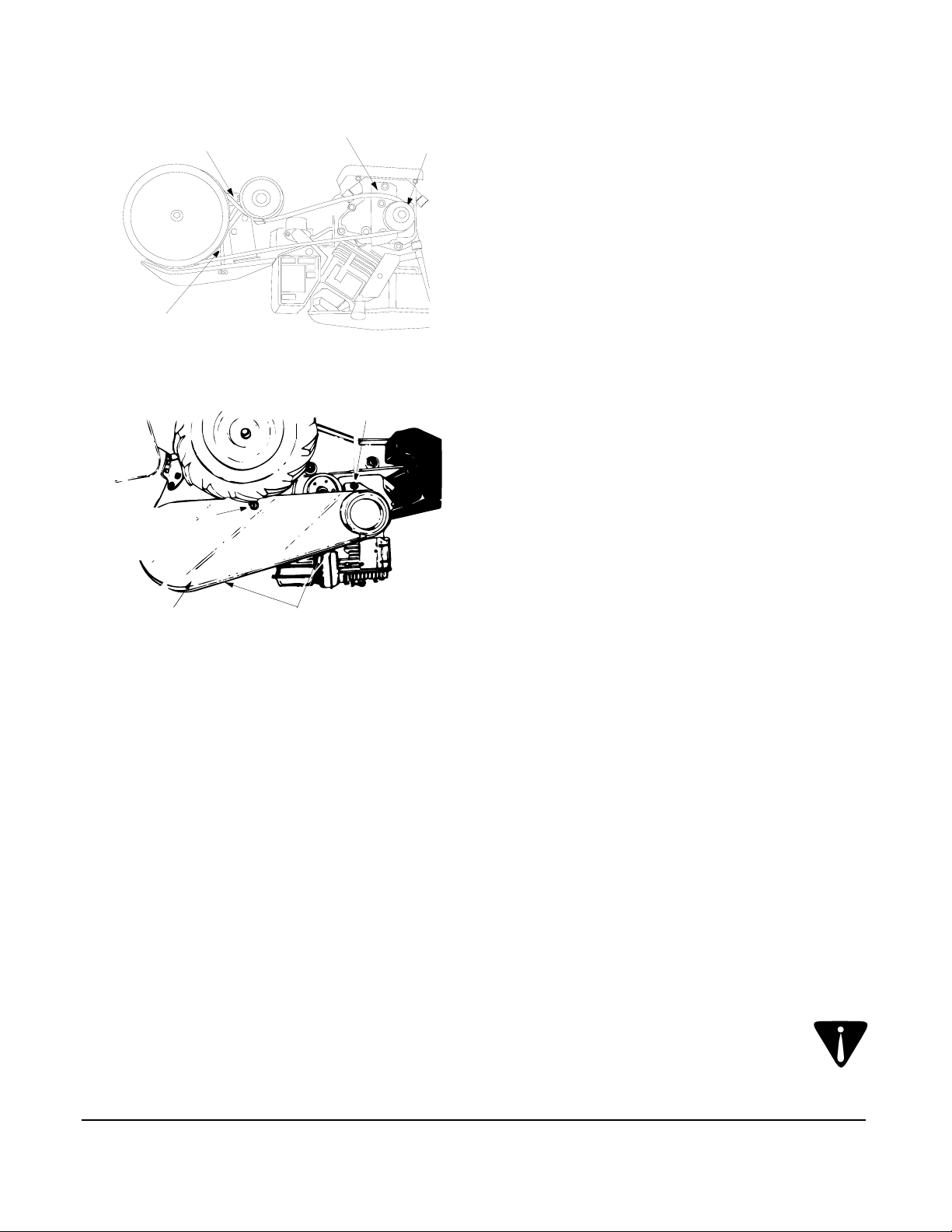
BELT REPLACEMENT
Your tiller has been engineered with a belt made of
special material (Kevlar Tensile) for longer life and
better performance. It should not be replaced with an
off-the-shelf belt.
If belt replacement is required, order belt or belts by
part number from your nearest authorized dealer.
Part No. 754-0434—‘‘V’’ Belt
1. Disconnect and ground the spark plug wire against the engine.
2. Remove the belt cover from the left side of the tiller as follows: See Figure 8. Remove two torx screws from the top of belt cover.
3. Remove the hex cap nut and flat washer from the side of the belt cover. Remove the hex screw at the bottom of the front of the cover.
4. Remove the belt keeper bracket located behind the engine pulley by removing two hex bolts and lock washers. See Figure 9.
5. Remove belt. Reassemble new belt, following instructions in reverse order.
Self Tap
Screw
Figure 8
Idler
Pulley
Rod
Engine
Pulley
Belt Keeper
Brkt.
Figure 9
Idler
Brkt.
TIRES
Recommended operating tire pressure is
approximately 20 p.s.i. (check sidewall of tire for tire
manufacturer’s recommended pressure). Maximum
tire pressure under any circumstances is 30 p.s.i.
Equal tire pressure should be maintained on both tires.
When installing a tire to the rim, be certain rim is clean
and free of rust. Lubricate both the tire and rim
generously. Never inflate to over 30 p.s.i. to seat
beads.
WARNING: Excessive pressure (over 30
p.s.i.) when seating beads may cause tire/
rim assembly to burst with force sufficient
to cause serious injury.
NOTE: Upon reassembly, make certain the belt is
routed over the idler pulley and inside of belt keepers
by engine pulley. See Figure 9.
SECTION 10: OFF-SEASON STORAGE
If the tiller will not be used for a period longer than 30
days, the following steps should be taken to prepare
the tiller for storage.
1. Clean the exterior of engine and the entire tiller thoroughly. Lubricate the tiller as described in the lubrication instructions.
12
2. We do NOT recommend the use of pressure washers to clean your unit. They may cause damage to electric components, spindles, pulleys, bearings or the engine. The use of pressure washers will result in shortened life and reduced serviceability.
Page 13

3. Refer to the engine manual for correct engine storage instructions.
4. Wipe tines with oiled rag to prevent rust.
5. Store tiller in a clean, dry area. Do not store next to corrosive materials, such as fertilizer.
NOTE: When storing any type of power equipment
in an unventilated or metal storage shed, care
should be taken to rustproof the equipment. Using a
light oil or silicone, coat the equipment, especially
any springs, bearings and cables.
SECTION 11: TROUBLE SHOOTING GUIDE
Trouble Possible Cause(s) Corrective Action
Engine fails to
start
Engine runs
erratic
Engine overheats
Tines do not
engage
Tines skip over
ground
Fuel tank empty, or stale fuel.
Throttle control lever not in correct
starting position (if so equipped).
Blocked fuel line.
Dirty aircleaner.
Choke not in ON position.
Spark plug wire disconnected.
Faulty spark plug.
Engine flooded.
Unit running on CHOKE.
Spark plug wire loose.
Blocked fuel line or stale fuel.
Vent in gas cap plugged.
Water or dirt in fuel system.
Dirty air cleaner.
Carburetor out of adjustment.
Engine oil level low.
Dirty air cleaner.
Air flow restricted.
Carburetor not adjusted properly.
Foreign object lodged in tines.
Tine clevis pin(s) missing.
Pulley and idler not in correct
adjustment.
Not shifting properly.
Control cable not adjusted properly.
Belt worn and/or stretched.
Improper rotation. Forward rotation should only be used on soil that has
Fill tank with clean, fresh gasoline. Fuel will not last over
thirty days unless a fuel stabilizer is used.
Move throttle lever to start position.
Clean fuel line.
Refer to the engine manual packed with your unit.
Move switch to ON position.
Connect wire to spark plug.
Clean, adjust gap or replace.
Refer to the engine manual packed with your unit.
Move choke lever to OFF position.
Connect and tighten spark plug wire.
Clean fuel line; fill tank with clean, fresh gasoline. Fuel will
not last over thirty days unless a fuel stabilizer is used.
Clear vent.
Drain fuel tank. Refill with fresh fuel.
Refer to the engine manual packed with your unit.
Refer to the engine manual packed with your unit.
Fill crankcase with proper oil.
Refer to the engine manual packed with your unit.
Refer to the engine manual packed with your unit.
Adjust carburetor as instructed in separate engine manual.
Dislodge foreign object.
Replace tine clevis pin(s).
Take unit to authorized service dealer.
Refer to Controls section of operator’s manual for proper
shifting procedures.
Adjust control cable (see assembly instructions).
Replace belt.
already been tilled, not on virgin soil.
Wheels do not
engage
Clevis pin missing.
Tiller is not being shifted properly.
Control cable not adjusted properly.
Belt worn and/or stretched.
Replace clevis pin.
Refer to Controls section of operator’s manual for proper
shifting procedures.
Adjust control cable (see assembly instructions).
Replace belt.
NOTE: For repairs beyond the minor adjustments above, contact your local authorized service dealer.
13
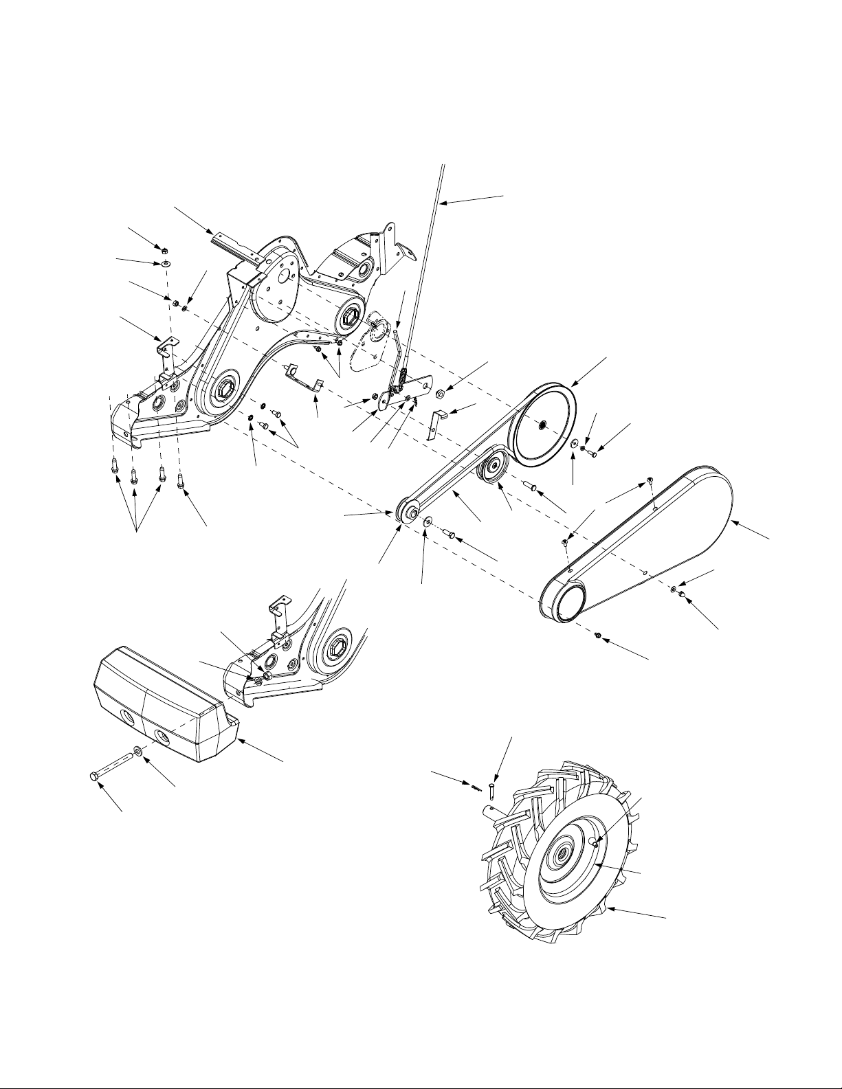
Page 14

13
16
52
10
12
34
29
16
55
45
36
1
18
36
8
55
53
17
6
3
5
36
42
23
7
22
32
47
46
21
37
33
40
31
28
17
44
15
27
43
4
20
50
51
34
29
45
26
41
16
55
36
55
19
16
14
44
14
35
49
54
33
14
16
2
36
24
28
25
10
9
14
48
14
11
Page 15

REF.
NO.
N°. DE
RÉF.
PART
NO.
N° DE
PIÈCE DESCRIPTION DESCRIPTION
1 611-0020 Wheel Shaft Ass'y 33T Arbre de roue 33 dents
2 611-0021 Tine Shaft Ass'y 18T Arbre de dents - 18 dents
3 611-0128 Jack Shaft Ass'y Arbre secondaire
4 611-0129 Input Shaft Ass'y Arbre
5 617-0058 Rev. Idler Gear Ass'y 30T Engrenage 30 dents
6 617-0059 Fr. Idler Gear Ass'y 30 T Engrenage 30 dents
7 617-0060 Tine Input Sprocket Ass'y 9T Pignon - 9 dents
8 617-0061 Wheel Input Sprocket Ass'y 10T Engrenage 10 dents
9 617-0062 Gear Ass'y 11T Engrenage 11 dents
10 686-0108 RH Housing Ass'y Boîtier de transmission - droite
11 710-0376 Hex. Scr 5/16-18 x 1.00 Gr. 5 Vis à tête hex. 5/16-18 x 1,00 Qual. 5
12 710-0599 Hex Wash S-Tapp Scr 1/4-20 x .50 Vis autotaraudeuse à rondelle hex. de 1/4-20 x 0,5
13 710-0604A Self-tapping Screw 5/16-18 x .625 Vis autotaraudeuse 5/16-18 x 0,625 po
14 710-3008 Hex Bolt 5/16-18 x .75" Lg. Gr. 5 Boulon hex. 5/16-18 x 0,75 po de lg. Qual. 5
15 711-1349 Input Shaft Arbre
16 712-0378 Hex Nut 7/16-20 Écrou à six pans 7/16-20
17 712-3004A Hex Flange L-Nut 5/16-18 Gr. 5 Contre-écrou de collet hex. 5/16-18 Qual. 5
18 713-0367 #420 Chain 1/2 Pitch x 50 Links-Endless Chaîne, no 420 pas de 1/2 x 50 maillons
19 713-0484 #50 Chain 5/8 Pitch x 54 Links Chaîne no 50, 5/8 x 54 maillons
20 716-0865 Snap Ring Joint
21 717-0853 Shifting Fork Fourchette
22 717-1582 Spur Gear 44T Engrenage 44 dents
23 717-1583 Spur Gear 30T Engrenage 30 dents
24 717-1584 Spur Gear 30T Engrenage 30 dents
25 717-1585 Spur Gear 44T Engrenage 44 dents
26 717-1587 Spur Gear 44T Engrenage 44 dents
27 717-1594 Spur Gear 16T Engrenage 16 dents
28 721-0378 Seal 1.0" Shaft Joint de 1,0 diam. arbre
29 721-0379 Seal .75 Shaft Joint de 0,75 diam. arbre
31 726-0277 Taper Cap Plug Bouchon à capuchon effilé
32 732-0496 Compression Spring .50" Lg. Ressort de compression 0,50 po de lg
33 736-0163 Flat Washer 1.03 ID x 1.62 OD x .03 Rondelle plate 1,03 DI x 1,62 DE x 0,03
34 736-0351 Flat Washer .76 ID x 1.5 OD x .03 Rondelle plate 0,76 DI x 1,5 DE x 0,03
35 736-0226 Flat Washer .469 ID x .88 OD x .063 Rondelle plate 0,469 DI x 0,88 DE x 0,063
36 736-0518 Thrust Wash. .445 ID x 1.92 OD Rondelle de butée 0,445 DI x 1,92 DE
37 736-3088 Flat Washer .635" ID x 1.59 OD Rondelle plate 0,635 DI x 1,59 DE
40 738-0645 Detent Shaft 1/2" Dia. Arbre à cliquet de 1/2 po de diamètre
41 738-0648 Jack Shaft 5/8" Dia. x 2.38 Arbre secondaire 5/8" diam. x 2,38
42 738-1013 Jack Shaft .625 x 5.0 Arbre secondaire 0,625 x 5,0
43 741-0124 Ball Bearing Roulement à billes
44 741-0420 Tine Shaft Brg. 1.002 x 2.50 Roulement de l'arbre des dents - 1,002 x 2,50
45 741-0421 Wheel Brg. .752" x 2.5” Roulement 0,752 po x 2,50 po
46 741-0563 Ball Bearing w/snap ring Roulement à billes avec bague
47 741-0862 Ball Detent .250 DIA Bille de verrouillage 0,250 dia.
48 750-0258 Spacer .315" ID x .375" Lg. Entretoise 0,315 DI x 0,375 po de lg.
49 750-0570 Step Spacer Cale d'espacement
50 750-0664 Spacer .505 ID x .88 OD Entretoise 0,505 DI x 0,88 DE
51 750-0671 Spacer .75" ID x .50" Lg. Entretoise 0,75 DI x 0,50 po de lg
52 786-0171 LH Chain Case Ass'y Ensemble de carter de chaîne de gauche
53 786-0238 Gear Positioner Bracket Support
54 736-0171 Lockwasher 7/16 ID Rondelle frein 7/16 DI
55 736-0407 Cupped Washer, .45 x 1.0 x .062 Rondelle creuse 0,45 x 1,0 x 0,062 po
686-0107 Gear Case Ass'y Complete Ensemble de carter de l'engrenage complet
214-450
11.28.03
15
Page 16

67
2
70
12
15
12
46
42
61
25
62
27
60
37
60
22
61
5
17
70
69
68
10
23
19
1
11
7
3
20
18
8
14
6
16
4
34
64
9
27
38
30
39
63
26
21
32
36
33
31
29
24
44
26
49
30
26
59
41
16
66
28
40
30
35
6
58
51
65
53
55
50
54
57
56
Page 17

REF.
NO.
N°. DE
RÉF.
1 747-1152 Shift Rod Tige de changement de vitesses
2 649-0041 Upper Handle Assembly Guidon supérieur
3 649-0034 Lower Handle Ass'y Guidon inférieur
4 710-3005 Hex Bolt 3/8-16 x 1.25 Boulon hex. 3/8-16 x 1,25
5 710-3056 Hex Bolt 5/16-18 x 3.25 Boulon hex. 5/16-18 x 3,25
6 711-0415 Clevis Pin 3/8 Dia Axe de chape 3/8 Dia.
7 712-0379 Hex Flange Nut 3/8-24 Thd. Écrou à six pans à collet de 3/8 - fil. 24
8 712-0429 Hex Ins. L-Nut 5/16-18 Gr. 5 Nylon Contre-écrou de blocage 5/16-18 Qual. 5 nylon
9 714-0147 Hairpin Goupille
10 720-0313 Grip Poignée
11 720-0210A Small "T" Knob Bouton en <<T>> (Petite)
12 720-0278A Foam Grip (2 req'd) Poignée de mousse (qté. 2)
14 726-0317 Cable Tie Attache câble
15 735-0246 Vinyl End Plug Bouchon - vinyl
16 736-0117 Flat Washer .385 ID x .62 OD x .033 Rondelle plate 0,385 DI x 0,62 DE x 0,033
17 736-0242 Cupped Washer .340 ID x .872 OD x .060 Rondelle creuse 0,340 DI x 0,872 DE x 0,060
18 738-0958 Shoulder Spacer Cale d'épaulement
19 784-0190 Handle Adj. Crank Manivelle de réglage du guidon
20 784-0191 Bracket Hex Nut Retainer Support de retenue à écrou à six pans
21 786-0120 Depth Bar Barre de profondeur d'attelage
22 747-1219 Clutch Bail Barre de commande de l'embrayage
23 786-0181 Shift Lever Rod Tige de levier de changement de vitesses
24 686-0044A Tine Shield Cover Ass'y Couvercle
25 710-0176 Hex Scr 5/16-18 x 2.75 Vis à tête hexagonale 5/16 x 2,75
26 710-3008 Hex Bolt 5/16-18 x .75" Lg. Gr. 5 Boulon hex. 5/16-18 x 0,75 po de lg. qual. 5
27 710-3097 Carriage Bolt 3/8-16 x 1.0" Lg. Boulon ordinaire 3/8-16 x 1,0 po de lg
28 712-0421 Wing Nut Écrou à oreilles
29 736-0169 L-Wash 3/8 ID Rondelle frein 3/8 DI
30 712-3004A Hex Flange L-Nut 5/16-18 Gr. 5 Contre-écrou de collet hex. 5/16-18 Qual. 5
31 726-0106 Push Cap Coiffe
32 738-0849 Hex Screw 5/16-18 x .75 Vis à tête hex. 5/16-18 x 0,75
33 747-0432 Tiller Flap Rod Tige de protecteur de dents
34 750-0885A Spacer .322 ID x .625 OD Entretoise 0,322 DI x 0,625 DE
35 786-0090 Side Shield Dispositif de protection latéral
36 786-0113 Rear Tine Shield Protecteur de dents
37 786-0176 RH Handle Brkt. Support du guidon - droite
38 786-0177 LH Handle Brkt. Support du guidon - gauche
39 786-0178 Tine Shield Bouclieur de dents
40 786-0179 Tine Shield Brkt. Support de bouclier de dents
41 786-0180 Shoulder Spacer Brkt. Support
42 686-0109 Shift Crank Ass'y Manivelle de changement de la vitesse
44 710-1017 Torx Mach. AB-Tapp Scr. 1/4 x .62" Lg. Vis torx AB 1/4 x 0,62 po de lg
46 715-0120 Spring Pin Roll 3/16 Dia. Goupille ronde à ressort de 5/16
49 784-0208C Shift Cover Couvercle
50 784-0160 Tine Adapter Ass'y 18” Adaptateur des dents 18 po
51 712-3054 Hex L-Nut 3/8-24 (Grade 5) Écrou de blocage 3/8-24 (qual. 5)
53 742-0305 13" Dia. Articulating Tine Dent d'articulation de 13 po de diamètre
54 738-0689 Shld. Scr. 1/2 Dia. x .175 Vis à épaulement 1/2 x 0,175
55 736-0208 Flat Washer .51 ID x 1.50 OD x .075 Rondelle plate 0,51 DI x 1,50 DE x 0,075
56 736-0253 Cupped Washer .505 ID x 1.00 OD x .075 Rondelle creuse 0,505 DI x 1,00 DE x 0,075
57 738-0688 Shld. Bolt 1/2" Dia. x .320 Boulon épaulée 1/2 diam. x 0,320
58 784-0205 Tine Ass'y Comp. 18” Ensemble des dents 18 po
59 714-0149B Internal Cotter Pin Goupille fendue interne
60 735-0127 Rubber Washer Rondelle en caoutchouc
61 714-0104 Int. Cotter Pin 5/16 Dia. Goupille fendue 5/16 dia.
62 710-3022 Hex Screw 3/8-16 x 2.75" Lg. Vis à tête hex 3/8-16 x 2,75 po de lg.
63 736-0204 Flat Washer .34 ID x .62 OD x .03 Rondelle plate 0,34 DI x 0,62 DE x 0,03
64 712-0431 Flanged Lock Nut 3/8-16 Gr. F Contre-écrou de collet hex. 3/8-16 Qual. F
65 736-0169 L-Wash 3/8 ID Rondelle frein 3/8 DI
66 712-3017 Hex Nut 3/8-16 Gr. 5 Écrou hex. 3/8-16 Qual. 5
67 710-0946 Truss Mach. Scr. 1/4-20 x .62" LG. Vis taraudée 1/4-20 x 0,62 po de lg
68 712-0324 Hex Ins. Locknut 1/4-20 Gr. 8 Nylon Écrou de blocage 1/4-20 Qual. 8 nylon
69 726-0273 Battery Hose Clamp Collier
70 736-3090 Flat Washer .260 x .72 x .060 Rondelle plate 0,260 x 0,72 x 0,060
PAR T
NO.
N° DE
PIÈCE DESCRIPTION DESCRIPTION
214-4501
10.12.04
17
Page 18
45
27
18
44
26
45
12
19
17
6
8
1
25
22
14
10
23
16
2
11
4
33
35
28
13
21
20
5
24
15
3
40
7
43
42
41
34
37
38
36
39
10
32
31
30
29
18
Page 19

REF.
NO.
N°. DE
RÉF.
PART
NO.
N° DE
PIÈCE DESCRIPTION DESCRIPTION
1 686-0111 Belt Cover Brkt Ass'y Support de couvercle de la courroie
2 710-0237 Hex Screw 5/16-24 x .625 Gr. 5 Vis à tête hexagonale 5/16-24 x 0,625 Qual. 5
3 710-0412 Hex Scr 1/4-28 x .75 Vis à tête hexagonale 1/4-28 x 0,75
4 710-0502A Hex Washer Scr 3/8-16 x 1.25 Vis à chapeau à six pans 3/8-16 x 1,25 po
5 710-0152 Hex Scr 3/8-24 x 1.00 Vis à tête hexagonale 3/8-24 x 1,00
6 710-0599 Hex Wash S-Tapp Scr 1/4-20 x .50 Vis autotaraudeuse à rondelle hex. de 1/4-20 x 0,5
7 710-0723 Hex Screw 3/8-16 x 1.25 Vis à tête hexagonale 3/8-16 x 1,25
8 712-0266 Hex Cent L-Nut 3/8-16 Contre-écrou de blocage 3/8-16
10 714-0104 Int. Cotter Pin 5/16 Dia. Goupille fendue 5/16 dia.
11 736-0104 Internal L-Washer Rondelle frein interne
12 736-0119 L-Wash 5/16 ID Rondelle frein 5/16 DI
13 736-0176 Flat Washer .265 ID x .938 OD x .120 Rondelle plate 0,265 DI x 0,938 DE x 0,120
14 736-0271 Shakeproof Spring Washer Rondelle anti-vibration
15 736-0329 L-Wash 1/4 ID Rondelle frein 1/4 DI
16 736-0452 Cupped Washer .396 ID x 1.140 OD Rondelle creuse 0,396 DI x 1,140 DE
17 738-0876 Shoulder Nut 7/16-20 Écrou à épaulement 7/16-20
18 746-1117 Clutch Cable Câble de l'embrayage
19 747-1159 Idler Pulley Rod Tige de poulie tendeur
20 754-0434 Belt: 4L x 58.16" Lg. Courroie: 4L x 58,16 po de lg.
21 756-0405 Flat Idler w/flanges 3-3/4" OD Tendeur plat à brides de 3-3/4 de po de DE
22 756-0971 Inner Engine Pulley Half Moitié intérieure de la poulie motrice
23 756-0972 Outer Engine Pulley Half Moitié extérieure de la poulie motrice
24 756-1162 Input Pulley Poulie
25 786-0064A Idler Bracket Support de tendeur
26 785-0186 Belt Keeper Brkt. Support
27 786-0187 Shift Cover Brkt. Support
28 786-0193 Idler Belt Keeper Protecteur de la courroie
29 634-0238 Wheel Ass'y RH 16 x 4 x 8 Gray Ensemble de roue CD 16 x 4 x 8 gris
634-0239 Wheel Ass'y LH 16 x 4 x 8 Gray Ensemble de roue CG 16 x 4 x 8 gris
734-0808 Tire Only (16") Pneu seulement (16 po.)
30 634-0108 Rim Only Jante seulement
31 734-0255 Air Valve Soupape à air
32 711-1017 Clevis Pin Axe de chape
33 710-0805 Hex Bolt 5/16-18 x 1.50" Lg. Gr. 5 Boulon hexagonal 5/16-18 x 1,50 po de lg Qual. 5
34 710-0382 Hex Bolt 1/2-13 x 5.00" Lg. Vis à tête hex. 1/2-13 x 5,00
35 712-0206 Hex Nut 1/2-13 Écrou hexagonal 1/2-13
36 723-0381 Counterweight 40 Lbs. Contre poids 40 lbs.
37 736-0326 Flat Washer .510 ID x 1.00 OD x .125 Rondelle plate 0,510 DI x 1,00 DE x 0,125
38 736-0921 L-Washer 1/2" ID Rondelle frein 1/2 DI
39 710-0653 Hex Wash HD Tapp Scr 1/4-20 x .38 Vis auto-taraudeuse hexagonale 1/4-20 x 0,38
40 710-1017 Torx Mach. AB-Tapp Scr. 1/4 x .62" Lg. Vis torx AB 1/4 x 0,62 po de lg.
41 712-0392 Hex Lock Stop Nut 1/4-28 Contre-écrou d'arrêt 1/4-28
42 736-3020 Flat Washer .266 ID x .625 OD Rondelle plate 0,266 DI x 0,625 DE
43 784-0158A Belt Cover Couvercle courroie
44 736-0242 Cupped Washer .340 ID x .872 OD x .060 Rondelle creuse 0,340 DI x 0,872 DE x 0,060
45 712-3010 Hex Nut 5/16-18 hd. Gr. 5 Écrou hexagonal 5/16-18 Qual. 5
737-0298 Oil Drain Tube Tuyau de vidange d'huile
737-0132 Pipe Cap 1/4 x 18 N.P.T. Capuchon de tuyau 1/4 x 18
215-4502
10.22.04
19
Page 20

TWO YEAR LIMITED WARRANTY
For TWO YEARS from the date of retail purchase within Canada, MTD PRODUCTS LIMITED will, at its option, re
pair or replace, for the original purchaser, free of charge, any part or parts found to be defective in material or
workmanship.
This warranty does not cover:
1. Any part which has become inoperative due to misuse, commercial use, abuse, neglect, accident, im
proper maintenance or alteration; or
2. The unit if it has not been operated and/or maintained in accordance with the owner’s instructions fur
nished with the unit; or
3. The engine or motor or component parts thereof which carry separate warranties from their manufac
turers. Please refer to The applicable manufacturer’s warranty on these items; or
4. Batteries and normal wear parts except as noted below. Log splitter pumps, valves and cylinders or
component parts thereof are covered by a one year warranty; or
5 Routine maintenance items such as lubricants, filters, blade sharpening and tune-ups, or adjustments
such as brake, clutch or deck; or
6. Normal deterioration of the exterior finish due to use or exposure.
Full Ninety Day Warranty on Battery: For ninety (90) days from the date of retail purchase, if any battery included
with this unit proves defective in material or workmanship and our testing determines the battery will not hold a
charge, MTD PRODUCTS LIMITED will replace the battery at no charge to the original purchaser.
Additional Limited Thirty Day Warranty on Battery: After ninety (90) days but within one hundred twenty (120)
days from the date of purchase, MTD PRODUCTS LIMITED will replace the defective battery, for the original purchaser, for a cost of one-half (1/2) of the current retail price of the battery in effect at the date of return.
Full Sixty Day Warranty on Normal Wear Parts: Normal wear parts are defined as belts, blade adapters, blades,
grass bags, seats, tires, rider deck wheels and clutch parts (friction wheels). These parts are warranted to the original purchaser to be free from defects in material and workmanship for a period of sixty (60) days from the date of
retail purchase.
How to Obtain Service: Warranty service is available, with proof of purchase, through your local authorized service dealer or distributor. If you do not know the dealer or distributor in your area, please write to the Service
Department of MTD PRODUCTS LIMITED, P. O. BOX 1386, KITCHENER, Ontario, N2G 4J1. The return of a com
plete unit will not be accepted by the factory unless prior written permission has been extended by MTD
PRODUCTS LIMITED.
Transportation Charges: Transportation charges for the movement of any power equipment unit or attachment
are the responsibility of the purchaser. Transportation charges for any part submitted for replacement under this
warranty must be paid by the purchaser unless such return is requested in writing by MTD PRODUCTS LIMITED.
Other Warranties: All other warranties, express or implied, including any implied warranty of merchantability is lim
ited in its duration to that set forth in this express limited warranty. The provisions as set forth in this warranty
provide the sole and exclusive remedy of MTD PRODUCTS LIMITED obligations arising from the sale of its prod
ucts.
MTD PRODUCTS LIMITED will not be liable for incidental or consequential loss or damage.
-
-
-
-
-
-
-
20
Page 21

16
NOTES
Page 22

15
rect.
-
MTD PRODUCTS LIMITED ne peut être tenue responsable pour toute perte ou tout dommage accidentel ou indi
découlant de la vente de ses produits.
dans cette garantie constituent le recours unique et exclusif quant aux obligations de MTD PRODUCTS LIMITED
de qualité marchande, se limitent à la durée stipulée dans cette garantie limitée expresse. Les conditions stipulées
Autres garanties: Toutes les autres garanties, qu’elles soient expresses ou tacites, y compris les garanties tacites
par MTD PRODUCTS LIMITED.
de cette garantie doivent être pris en charge par l’acheteur, sauf si le renvoi de la machine est demandé par écrit
charge de l’acheteur. Les frais de transport d’une pièce quelconque envoyée à des fins de remplacement en vertu
Frais de transport: Les frais relatifs au transport de toute machine motorisée ou de tout accessoire sont à la
LIMITED.
accepter le renvoi d’une machine complète si une autorisation n’a pas été accordée par écrit par MTD PRODUCTS
service après-vente de MTD PRODUCTS LIMITED, C.P. 1386, Kitchener (Ontario) N2G 4J1. L’usine ne peut
vous ne connaissez pas l’adresse de l’atelier de réparations ou du distributeur de votre région, adressez-vous au
Pour faire honorer la garantie: Présentez une preuve d’achat à l’atelier de réparations ou au distributeur agréé. Si
détail.
matière et de fabrication à l’acheteur initial pour une période de soixante (60) jours à partir de la date d’achat au
frottement) sont considérés comme des pièces à usure normale. Elles sont garanties exemptes de vices de
sacs à herbe, sièges, pneus, roues du plateau de coupe des tondeuses à siège, et pièces d’embrayage (roues de
Garantie complète de soixante jours des pièces à usure normale: Les courroies, adaptateurs de lame, lames,
vigueur au moment du retour de la batterie.
remplacer la batterie défectueuse à l’acheteur initial pour la moitié du prix de vente au détail de la batterie, en
jours, mais dans un délai de cent vingt (120) jours de la date d’achat, MTD PRODUCTS LIMITED s’engage à
Garantie limitée supplémentaire de trente jours de la batterie: A l’expiration du délai de quatre-vingt-dix (90)
délai de quatre-vingt-dix (90) jours à partir de la date d’achat au détail.
vice de matière ou de fabrication et si nos essais confirment qu’elle ne peut pas maintenir une charge, dans un
gratuitement la batterie à l’acheteur initial, si la batterie fournie avec la machine s’avère défectueuse en raison d’un
Garantie complète de quatre-vingt-dix jours de la batterie: MTD PRODUCTS LIMITED s’engage à remplacer
tion aux intempéries.
-
6. La détérioration normale de la finition extérieure du fait de l’utilisation de la machine et de son exposi
réglages des freins, de l’embrayage ou du plateau de coupe;
5. Les articles d’entretien courant tels que les lubrifiants, filtres, aiguisage de lames et révisions, ou les
soupapes et cylindres des fendeuses à bois sont garantis pendant un an;
4. Les batteries et les pièces présentant une usure normale énumérées plus bas. Les pompes,
respectifs. Veuillez consulter la garantie qui s’applique à la pièce en particulier;
3. Le moteur, le moteur électrique ou l’un de ses composants car ils sont garantis par leurs fabricants
l’accompagnaient;
2. La machine si elle n’a pas été utilisée et/ou entretenue conformément aux instructions qui
abusif, une négligence, un entretien incorrect ou une modification;
1. Les pièces rendues inutilisables par un emploi incorrect, une utilisation commerciale, un emploi
Cette garantie ne couvre pas:
de DEUX ANS à partir de la date d’achat au détail au Canada.
pièce ou partie de pièce qui s’avère défectueuse en raison d’un vice de matière ou de fabrication, dans un délai
MTD PRODUCTS LIMITED s’engage à réparer ou à remplacer gratuitement, à son choix, à l’acheteur initial, toute
PIÈCES SOUS GARANTIE ET SERVICE APRÈS-VENTE
Page 23

14
n
technique agréée.
REMARQUE: Pour toute réparation autre que les ajustements mineurs ci-dessus, adressez-vous à la statio
Remplacez la courroie.
Réglez le câble de commande (voir les instructions).
d’utilisation.
le chapitre sur les commandes de la notice
V oir les instructions de changement de vitesses dans
Remplacez l’axe de chape.
travaillée.
être employée sur le sol meuble, non sur le sol non
Remplacez la courroie.
Réglez le câble de commande (voir les instructions.)
d’utilisation.
le chapitre sur les commandes de la notice
V oir les instructions de changement de vitesses dans
agréée
Faites réparer la machine par une station technique
Remplacez l’axe de chape des dents.
Dégagez l’objet.
Consultez la notice d’utilisation du moteur
Faites le plein d’huile du carter.
Consultez la notice d’utilisation du moteur.
Consultez la notice d’utilisation du moteur.
L’évent du capuchon du réservoir est bouchée.
Consultez la notice d’utilisation du moteur.
Consultez la notice d’utilisation du moteur.
propre et fraîche.
videz le réservoir. Faites le plein avec une essence
Débranchez la conduite d’essence au carburateur et
une essence propre et fraîche.
Nettoyez la conduite d’essence. Faites le plein avec
Branchez et serrez le fil de la bougie.
Ouvrez le volet de départ.
Nettoyez la canalisation.
Consultez la notice d’utilisation du moteur.
bougie.
Nettoyez, réglez l’écartement ou remplacez la
d’utiliser un stabilisateur de carburant.
L’essence doit être utilisée dans les 30 jours à moins
Faites le plein avec une essence propre et fraîche.
Branchez le fil à la bougie.
Ouvrez le volet de départ.
démarrage.
Placez la commande des gaz à la position de
Consultez la notice d’utilisation du moteur.
Courroie usée ou étirée.
Mauvais réglage du câble de commande.
changées correctement.
Les vitesses du motoculteur ne sont pas
L’axe de chape est manquant.
Rotation inexacte. La rotation des dents vers l'avant devrait seulement
Courroie usée ou étirée.
Mauvais réglage du câble de commande.
changées correctement.
Les vitesses du motoculteur ne sont pas
correctement réglées.
La poulie et la poulie de tension ne sont pas
L’axe de chape des dents est manquant.
Objet dans les dents.
La circulation d’air est gênée.
Niveau d’huile trop bas.
Filtre à air sale.
Carburateur mal réglé.
Vent in gas cap plugged.
Filtre à air sale.
Carburateur mal réglé.
Eau ou saleté dans le système de carburant.
essence éventée.
Conduite d’essence bouchée ou
Fil de la bougie desserré.
Volet de départ fermé.
Canalisation de carburant bouchée.
Moteur noyé.
Bougie défectueuse.
éventée.
Le réservoir est vide ou l’essence est
Fil de la bougie débranché.
Volet de départ fermé.
position de démarrage.
La commande des gaz ne se trouve pas en
Filtre à air sale.
s’enclenchent pas.
Les roues ne
dessus la terre.
Les dents saut au-
s’enclenchent pas.
Les dents ne
chauffe.
Le moteur sur-
irrégulièrement.
Le moteur tourne
démarre pas.
Le moteur ne
Problème Cause(s) Possible(s) Solution
CHAPITRE 13: GUIDE DE DÉPANNAGE
Page 24

13
mobiles, avec une huile légère ou de la silicone.
machine, en particulier les câbles et toutes les pièces
un abri métallique non ventilé. Enduisez toute la
le matériel contre la rouille s’il doit être entreposé dans
REMARQUE: Il est très important de bien protéger
comme des engrais par exemple.
sec. Ne le remisez pas près de produits corrosifs
5. Remisez le motoculteur dans un endroit propre et
pour les empêcher de rouiller.
4. Essuyez les dents avec un chiffon imbibé d’huile
aux instructions de remisage.
3. Consultez la notice d’utilisation du moteur quant
motoculteur et à limiter sa facilité d’entretien.
d’eau a tendance à raccourcir la vie du
poulies, les roulements ou le moteur. L’emploi
les composants électriques, les fusées, les
déconseillée. Cela risque en effet d’endommager
boyau d’arrosage pour nettoyer le tracteur est
2. L’utilisation d’un nettoyeur sous pression ou d’un
instructions.
motoculteur. Lubrifiez le motoculteur selon les
1. Nettoyez l’extérieur du moteur et tout le
la façon suivante.
pendant une période de plus de 30 jours, procédez de
Si vous ne prévoyez pas d’utiliser le motoculteur
CHAPITRE 12: REMISAGE HORS SAISON
et provoquer des blessures graves.
effet faire éclater l’ensemble pneu et jante
talons. Une pression excessive peut en
pour installer les
2
à plus de 30 lb/po
AVERTISSEMENT: Ne gonflez jamais
pour installer les talons.
2
. Conservez une
2
30 lb/po
pneu et la jante. Ne gonflez jamais le pneu à plus de
rouille avant d’y installer un pneu. Lubrifiez bien le
Assurez-vous toujours que la jante est propre et sans
pression égale sur les deux pneus.
toujours être inférieure à 30 lb/po
souvenez-vous que la pressions maximale doit
renseignement ne figure pas sur vos pneus,
pneu, inscrite sur le flanc de celui-ci. Si ce
pression maximale, recommandée par le fabricant du
La pression recommandée est de 20 lb/po2. Vérifiez la
PRESSION DES PNEUS
tendeur. Voir la Figure 10 .
entre les dispositifs de retenue près de la poulie du
courroie passe au-dessus de la poulie du tendeur et
REMARQUE: Lors du remontage, vérifiez que la
Page 25
12
Figure 10
du guide
de tendeur
Support
Support
motrice
Poulie
garantit une durée de vie plus longue et vous assure
matériau spécial, à savoir du Kevlar Tensile, qui leur
Le motoculteur utilise des courroies réalisées dans un
REMPLACEMENT DE LA COURROIE
gravement endommager la machine.
en particulier dans le carter à chaîne et peut
L’eau risque de pénétrer partout dans le motoculteur,
nettoyage sous pression pour nettoyer le motoculteur.
IMPORTANT: N’utilisez jamais un appareil de
tension
poulie de
Tige de la
Figure 9
Écrou à six pans
à capuchon
Écrou a six pans
Couvre-courroie
Vis auto-taraudeuses
en procédant dans l’ordre inverse.
5. Démontez la courroie. Installez la courroie neuve
Figure 10.
boulons hex. et les deux rondelles-frein. Voir la
derrière la poulie motrice en retirant les deux
4. Démontez le support du guide qui se trouve
couvre-courroie.
courroie. Enlevez la vis hex. sur le bas à l’avant du
plate qui se trouvent sur le côté du couvre-
3. Enlevez l’écrou à six pans à chapeau et la rondelle
courroie.
les deux auto-taraudeuses du dessus du couvremotoculteur comme suit. Voir la Figure 9 . Enlevez
2. Démontez le couvre-courroie du côté gauche du
terre contre le moteur.
1. Débranchez le fil de la bougie et mettez-le à la
754-0434 - Courroie trapézoïdale.
à la station technique la plus proche. Pièce de la no. modèle nécessaire en indiquant le numéro de la pièce
Si vous devez remplacer les courroies, commandez le
n’importe quelle courroie.
de meilleures performances. Ne les remplacez pas par
quelconque.
réparation ou une opération d’entretien
contre le moteur avant d’effectuer une
de la bougie et mettez-le à la masse
AVERTISSEMENT: Débranchez le fil
la rouille ou dommages de l'eau.
couche mince de l’huile ou de silicone pour empêcher
motoculteur avec une serviette après et appliquez une
à enlever si elle n’est pas sèche. Essuyez toujours le
dents après chaque utilisation. La saleté est plus facile
Nettoyez le dessous du dispositif de protection des
NETTOYAGE DES DENTS
et saleté sont éliminés de la proximité du silencieux.
à la durabilité du moteur. Vérifiez que tous les débris
bonne circulation d’air essentielle aux performances et
(compartiment du ventilateur) propre pour assurer la
une brosse. Gardez le système de refroidissement
Nettoyez régulièrement le moteur avec un linge ou
quant au type de bougie à utiliser et à l’écartement.
saison. Consultez la notice d’utilisation du moteur
moteur. Remplacez la bougie au début de chaque
réglé toutes les 25 heures de fonctionnement du
La bougie doit être nettoyée et l’écartement doit être
le filtre à air n’est pas complètement installé fournie.
IMPORTANT: Ne faites jamais tourner le moteur si
avant de nettoyer le filtre à air.
Consultez la notice d’utilisation du moteur fournie
sont des indications que le filtre à air doit être nettoyé.
Une mauvaise performance du moteur et sa «noyade»
chaque heure dans des conditions très poussiéreuses.
toutes les dix heures de fonctionnement. Nettoyez-le
Dans les conditions normales, nettoyez le filtre à air
attentivement les instructions et suivez-les.
d’utilisation du moteur fournie avec la tondeuse. Lisez
Utilisez l’huile à moteur recommandée dans la notice
tout ce qui concerne l’entretien du moteur.
Consultez la notice d’utilisation du moteur pour
MOTEUR
CHAPITRE 11: ENTRETIEN
fois par saison et lubrifiez-les avec de l’huile.
Arbre des roues—Démontez les roues au moins une
fois par saison et lubrifiez-les avec de l’huile.
Arbre des dents—Démontez les dents au moins une
Page 26

11
Commandez la pièce no 737-0300.
fois par saison avec une huile légère.
pivotement et les tringles de commande au moins une
Points de pivotement — Lubrifiez tous les points de
facilement dans les deux directions.
une fois par saison. La commande doit bouger
de commande de l’embrayage et le câble au moins
huile légère, lubrifiez le point de pivotement de la barre
Barre de commande de l’embrayge — Avec une
graisse chez le concessionnaire agréé le plus proche.
la moitié gauche. Vous pouvez vous procurer la
Versez 30 onces de graisse Benalene 920. Assemblez
posez la moitié droite de la transmission sur son côté.
raison quelconque. Pour faire le plein de graisse,
aucune vérification sauf si elle est démontée pour une
fermée hermétiquement à l’usine. Elle ne nécessite
Transmission — La transmission a été lubrifiée et
CHAPITRE 10: LUBRIFICATION
pas serrée), il faut effectuer le réglage.
poulie de tension (quand la barre d’embrayage n’est
avant. Si le support de l’indicateur tou che la tige de la
d’utilisation du moteur fournie avec le motoculteur.
des réglages sont nécessaires, consultez la notice
l’usine conviennent dans la plupart des situations. Si
Ne faites jamais de réglages inutiles. Les réglages de
pas les surfaces chaudes ni le silencieux.
toutes les pièces mobiles et ne touchez
embrayages et lames. Éloignez-vous de
carburateur), débrayez tous les
pendant qu’il tourne (par ex. au
des réglages quelconques au moteur
AVERTISSEMENT: Si vous devez faire
RÉGLAGES DU CARBURATEUR
chaque vitesse en marche avant.
touche pas le support indicateur en passant à
6. Vérifiez que la tige de la poulie de tension ne
en place.
5. Remettez la rondelle ondulée et la goupille-épingle
Voir la Figure 10.
trou le plus bas du support de la poulie de tension.
4. Déplacez la tige de la poulie de tension dans le
tige de la poulie de tension. Voir la Figure 10.
3. Retirez la goupille-épingle et la rondelle plate de la
sur le remplacement de la courroie, à la page 12.
2. Démontez le couvre-courroie décrit dans la section
masse contre le moteur.
1. Débranchez le fil de la bougie et mettez-le à la
d’utilisation.
d’instructions spéciales dans la notice
pendant que le moteur tourne, sauf en cas
d’effectuer un réglage quelconque
AVERTISSEMENT: N’essayez jamais
sélection des vitesses à chaque mode en marche
l’embrayage non serrée, passez la manette de
Le moteur à l’arrêt et la barre de commande de
vérification est simple à faire.
ajuster la tige de la poulie de tension. Cette
Si la courroie est très étirée, il faudra peut-être aussi
instructions de montage.
section concernant le réglage de l’embrayage des
Pour régler la tension de la courroie, consultez la
que le moteur tourne au même régime.
rotation des dents ou des roues paraît saccadée et
de la courroie. Un ajustement est nécessaire quand la
tre rendu nécessaire par l’usure normale et l’étirement
Le réglage périodique de la tension de la courroie peut
COURROIE
RÉGLAGE DE LA TENSION DE LA
renseignements.
chapitre sur les commandes pour plus de
On peut ajuster la hauteur du guidon. Consultez le
RÉGLAGES DU GUIDON
CHAPITRE 9: RÉGLAGES
de reculer et de blesser quelqu’un.
embrayées. Le motoculteur risque en effet
soulèvent du sol quand les dents sont
dents pénètrent dans la terre.
profondément) pour vous assurer que les
guide de profondeur (travaillez moins
tournent en marche avant, abaissez le
AVERTISSEMENT: Quand les dents
de la largeur) pour bien pulvériser la terre.
deux fois le potager (dans le sens de la longueur, puis
Vous obtiendrez de meilleurs résultats en labourant
les guidons pour que les roues se
AVERTISSEMENT: N’appuyez pas sur
dents. Embrayez seulement les roues.
Pour déplacer le motoculteur, n’enclenchez pas les
entre deux vitesses, le moteur va caler.
d’enclencher la manette d’embrayage. S’il se trouve
de la vitesse est correctement positionné avant
REMARQUE: Vérifiez que l’indicateur de sélection
Page 27

7 po.
5 po.
haute
(profond) la plus
pour la position
Utilisez ce trou
latéraux
protections
Dispositif de
3 po.
1 po.
déplacement
Position de
10
vitesse.
complètement arrêté avant de changer la
Attendez que le motoculteur soit
les roues ou les dents sont embrayées.
manette de sélection de la vitesse quand
AVERTISSEMENT: Ne déplacez pas la
arrière.
l’une des positions de marche avant ou en marche
3. Placez la manette de sélection de la vitesse à
la page 9.
2. Mettez le moteur en marche de la façon indiquée à
1. Choisissez le réglage du guide de profondeur.
embrayer les roues et les dents.
4. Appuyez la manette contre le guidon pour
avant pour travailler de la terre meuble.
une terre dure. Faites tourner les dents en marche
arrière dans de la terre non travaillée, du gazon ou
IMPORTANT: Faites tourner les dents en marche
Figure 8
la plus basse
(peu profond)
pour la position
Utilisez ce trou
chape
Axe de
première fois
position la
Utilisez cette
réglage.
contre le moteur avant d’effectuer tout
de la bougie et mettez-le à la masse
MOTOCULTEUR:
UTILISATION PROPREMENT DITE DU
écrous à oreilles et serrez à fond.
panneau latéral à la position voulue. Replacez les
panneaux latéraux. Voir la Figure 8. Placez un
Enlevez les écrous à oreilles pour ajuster les
en place avec l’axe de chape et la goupille épingle.
le guide de profondeur à la position voulue. Maintenez
ajuster le guide de profondeur. Voir la Figure 8. Placez
Enlevez l’axe de chape et la goupille épingle pour
profondeur (trou du haut).
4. Pour déplacer le motoculteur, abaissez le guide de
haute.
Relevez les dispositifs latéraux à la position la plus
(trou inférieur) pour travailler profondément.
guide de profondeur à la position la plus haute
3. Pour travailler une terre non compacte, relevez le
effectuez un ou deux passages.
de profondeur et les dispositifs latéraux et
Pour travailler plus profondément, relevez le guide
protection latéraux à la position la plus basse.
partir du haut). Installez les dispositifs de
une profondeur de travail de 1 po (deuxième trou à
profondeur, employez le réglage correspondant à
2. Pour retourner l’herbe et sarcler à faible
haut (profondeur de travail: 1 po). Voir la Figure 8.
employez le deuxième trou de régla ge à partir du
1. Lors de la première utilisation du motoculteur,
débranché et mis à la masse contre le moteur.
guide de profondeur. Vérifiez que le fil de la bougie est
protection latéraux comme à la Figure 8 en réglant le
différentes. Voir la Figure 8. Ajustez les dispositifs de
profondeur qui peut être réglé à cinq positions
La profondeur de travail es t contrôlée par le guide de
AVERTISSEMENT: Débranchez le fil
CHAPITRE 8: MODE D’EMPLOI DU MOTOCULTEUR
dans le chapitre «Assemblage».
fonctionnement. Consultez «Réglez l'embrayage»
l’embrayage après les dix premières heures de
REMARQUE: Vérifiez à nouveau le réglage de
Page 28

9
quand l’équipement n’est pas surveillé.
terre pour empêcher tout démarrage accidentel
2. Débranchez le fil de la bougie et mettez-le à la
«STOP» (Arrêt).
1. Placez la commande de l’obturateur à la position
de moteur à la position «START».
«FAST» (lapin). Placez la commande de vitesse
2. Placez la commande de l’obturateur à la position
POINT MORT.
1. Placez la manette de sélection de la vitesse au
POUR ARRÊTER LE MOTEUR
au moment du démarrage.
«Assemblage», «Réglez l'embrayage».
l'embrayage qui est expliqué dans le chapitre
d'utiliser le motoculteur, vérifiez le réglage de
REMARQUE: Quand le moteur tourne et avant
moteur pour obtenir plus de renseignements.
REMARQUE: Veuillez lire la notice d'utilisation du
nouveau de la déplacer.
revenez à la position de départ, puis essayez à
vers la position «Run». Si le moteur hésite,
progressivement la commande du volet de départ
tourner plus régulièrement, déplacez
7. Quand le moteur est chaud et qu'il commence à
moteur démarre.
6. Répétez les paragraphes 3 et 4 jusqu’à ce que le
démarreur.
revenir lentement en tenant bien la poignée du
poignée claquer contre le moteur. Laissez la corde
5. Tirez rapidement sur la corde. Ne laissez pas la
revenir lentement.
sentiez une légère résistance. Laissez la corde
poignée et tirez-la lentement jusqu’à ce que vous
4. Placez-vous à côté du motoculteur, prenez la
si le moteur est chaud.
REMARQUE: Cette opération n’est pas néces saire
chaque poussée.
(3) fois. Attendez environ deux (2) secondes entre
poussez le bouton d’amorçage deux (2) ou trois
position «CHOKE» (Volet fermé) ou si équipé,
3. Déplacez la manette du volet de départ à la
motoculteur quand le moteur tourne ou
personne ne se trouve devant le
AVERTISSEMENT: Vérifiez que
(engrenages) qui est normal.
moteur ne tourne pas, vous entendrez un cliquetis
REMARQUE: Si vous poussez la machine quand le
DÉMARRAGE DU MOTEUR
tourne ou s’il est chaud.
l’intérieur ou pendant que le moteur
d’exploser. Ne faites jamais le plein à
inflammable et les vapeurs risquent
s’agit d’un produit extrêmement
attention en manipulant de l’essence. Il
AVERTISSEMENT: Faites très
Lisez attentivement les instructions.
moteur, fournie avec la motoculteur.
les instructions fournies dans la notice d’utilisation du
Faites le plein d’essence et d’huile de moteur selon
MARCHE
AVANT DE METTRE LE MOTEUR EN
d’utilisation avant de la mettre en marche.
sur la machine et dans la notice
instructions et avertissements q ui figurent
lire, comprendre et de suivre toutes les
AVERTISSEMENT: Assurez-vous de
IMPORTANT: Le moteur est expédié SANS huile.
CHAPITRE 7: FONCTIONNEMENT
d’entraînement des roues et des dent s.
guidon pour enclencher les mécanismes
MODE D’EMPLOI DU MOTOCULTEUR à la page 10.
Il contrôle la profondeur de travail. Lire CHAPITRE 8:
GUIDE DE PROFONDEUR
blocage. Voir la Figure 7.
guidon à la position désirée. Serrez le dispositif de
guidon de quelques tours. Relevez ou abaissez le
dispositif de blocage du réglage de la hauteur du
La hauteur du guidon peut être réglé. Desserrez le
RÉGLAGE DU GUIDON
l’embrayage en changeant de vitesse.
REMARQUE: N’enclenchez jamais la manette de
la barre de commande de l’embrayage contre le
Elle se trouve sous le guidon. Voir la Figure 7. Serrez
BARRE DE COMMANDE DE L’EMBRAYAGE
commandes de moteur.
l'information et des fonctions additionnelles des
Consultez la notice d’utilisation de moteur pour
COMMANDES DE MOTEUR
démarrer un moteur froid.
mélange de carburant dans le carburateur pour faire
Il est placé derrière le filtre à air et sert à enrichir le
BOUTON D’AMORÇAGE
Page 29
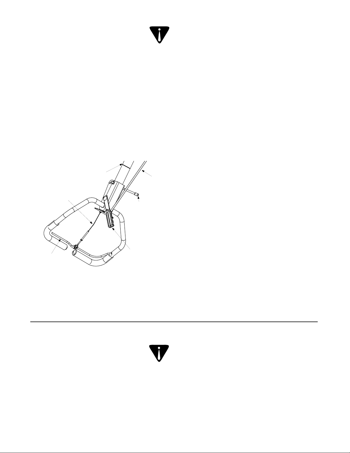
de la câble
Commande
l’embrayage
commande de
Barre de
8
faire démarrer le moteur.
motoculteur est au POINT MORT avant de
AVERTISSEMENT: Vérifiez que le
enclencher les dents.
d’embrayage est enclenchée, sauf pour
changez pas de vitesse quand la barre
des dents, relâchez la barre d’embrayage. Ne
• Pour arrêter la marche avant et le mouvements
synchronisation des engrenages.
barre d’embrayage pour permettre la
sélecteur de vitesse et enclenchez lentement la
marche avant, poussez légèrement sur le
• Pour enclencher les roues et les dents en
engrenages se synchronisent.
motoculteur, puis faites-le reculer pour que les
arrière, faites légèrement avancer le
• Pour enclencher les roues en marche avant ou
Figure 7
Attache-câble
commande
Tige de la
avant pour travailler de la terre meuble.
une terre dure. Faites tourner les dents en marche
arrière dans de la terre non travaillée, du gazon ou
IMPORTANT: Faites tourner les dents en marche
des dents en marche avant.
Dents en marche avant — Entraînement des roues et
marche arrière.
en marche avant et entraînement des dents en
Dents en marche arrière — Entraînement des roues
en marche avant seulement.
Roues en marche avant — Entraînement des roues
MARCHE AVANT —
marche arrière.
MARCHE ARRIÈRE — Entraînement des roues en
mort.
POINT MORT — La transmission se trouve au point
désiré. Voir la Figure 7.
de vitesses corresponde au mode de fonctionnement
que l’indicateur sur le dessus du couvercle de la boîte
(voir ci-dessous). Tirez ou poussez cette manette pour
ARRIÈRE ou l’un des modes de MARCHE AVANT
sert à sélectionner le POINT MORT, la MARCHE
Elle se trouve au milieu du guidon du motoculteur et
MANETTE DE SÉLECTION DE LA VITESSE
hauteur du guidon
réglage de la
blocage du
Dispositif de
la vitesse
sélection de
Manette de
synchronisent.
ou reculer le motoculteur pour que les vitesses se
levier du sélecteur de vitesses, faites un peu avancer
REMARQUE: En cas de difficulté pour déplacer le
moteur pour plus de renseignements.
moteur froid. Veuillez lire la notice d’utilisation du
dans le carburateur pour faciliter la mise en route d’un
l’obturateur et sert à enrichir le mélange de carburant
Il se trouve sur la gauche de la commande de
VOLET DE DÉPART (si équipé)
renseignements.
la notice d’utilisation du moteur pour plus de
régler le régime du moteur et d’arrêter le moteu r. Voir
Cette manette se trouve du moteur. Elle permet de
COMMANDE DE L’OBTURATEUR
CHAPITRE 6: COMMANDES
deux pneus.
Maintenez une pression égale dans les
les conditions, est de 30 lb/po2.
maximale des pneus, quelles que soient
AVERTISSEMENT: La pression
recommandations du fabricant sur le flanc du pneu).
recommandée est de 20 lb/po2 environ. (Vérifiez les
avant d’utiliser la machine. La pression de travail
pour l’expédition. Réduisez la pression des pneus
Les pneus du motoculteur ont peut-être été surgonflés
PRESSION DES PNEUS
pans au guidon.
l’extrémité de la gaine. Ajustez ensuite les écrous à six
les écrous à six pans à l’autre extrémité du câble, vers
nécessaire, démontez le couvre-courroie et déplacez
REMARQUE: Si un réglage supplémentaire est
Vérifiez les deux réglages et ajustez selon le besoin.
l’écrou contre le tube.
(à partir de la position de conduite), puis resserrez
tours dans le sens contraire aux aiguilles d’une montre
à l’extrémité du câble en lui faisant faire quelques
est enclenchée en marche avant, desserrez le tube
Si les roues ne tournent pas lorsque la machine
Les roues doivent tourner.
barre de commande de l’embrayage contre le guidon.
(roues avant). Embrayez doucement en amenant la
Déplacez le levier de vitesses à la position FORWARD
Page 30

Figure 6
Goupille épingle
indicateur
Support
commande
Tige de
doigts sous le couvre-courroie.
AVERTISSEMENT: Ne placez pas vos
Faites le plein d’huile et d’essence
de tension
Tige de la poulie
caoutchouc
Rondelle en
7
contre le tube.
de la position de conduite), puis resserrez l’écrou
tours dans le sens des aiguilles d’une montre (à partir
à l’extrémité du câble en lui faisant faire quelques
n’est pas pressée, desserrez le tube à filetage interne
Si la courroie tourne quand la barre d’embrayage
pas.
que la courroie (dans le couvre-courroie) ne tourne
Placez-vous sur la droite du motoculteur pour vérifier
marche.
point mort («NEUTRAL»), mettez le moteur en
un mur par exemple. Placez le levier de vitesses au
Appuyez le contrepoids avant du motoculteur contre
d’utilisation du moteur fournie avec le motoculteur.
avant de vérifier ce réglage. Consultez la notice
IMPORTANT:
1/4 po
Écrou de
interne
filetage
Tube à
RÉGLAGE DÉFINITIF DE L’EMBRAYAGE
plates
Rondelles
Vis à tête fendue
Figure 5
3
/
4
”
Figure 4
no 10
Écrou
fileté à oeil
Boulon
briser.
commande. Une tension trop importante risque de le
REMARQUE: Ne serrez pas excessivement le fil de
du câble. Voir la Figure 5.
filetage. Serrez l’écrou contre le tube à l’extrémité
l’extrémité du câble. Enfoncez environ 3/4 po de
paragraphe 1, dans le tube à filetage interne à
6. Filetez le boulon à oeil et l’écrou n° 10, retirés au
d’embrayage
Barre
quart de pouce (1/4 po).
attache, boulon à oeil, ro ndelle plate et écro u d’un
comme suit : vis à tête fendue, rondelle plate,
Les pièces doivent être installées de haut en bas
d’embrayage de la façon illustrée à la Figure 5.
5. Installez le boulon fileté à oeil sur la barre
rondelles plates de la barre d’embrayage.
4. Enlevez la vis à tête fendue, l’écrou et les deux
.
Voir la Figure 7
de vitesse et attachez-la avec la goupille-épingle.
commande dans le trou de la poigné e du s électeu r
4. Faites passer l'extrémité plus longue de la tige de
paragraphe 1. Voir la Figure 6.
maintenez-la avec la goupille-épingle retirée au
trouve sur le couvercle du levier de vitesses et
commande dans le support indicateur qui se
3. Enfoncez l'extrémité courte (courbée) de la tige de
caoutchouc sur celle-ci.
tige de commande, mais laissez les rondelles en
2. Retirez les goupilles-épingle qui se trouvent sur la
haute.
1. Vérifiez que le guidon est réglé à la position la plus
écrou et rondelles plates
Vis à tête fendue,
COMMANDE
INSTALLATION DE LA TIGE DE
machine en marche.
du câble d’embrayage avant de mettre la
AVERTISSEMENT: Vérifiez le réglage
plastique
Raccord en
interne
Tube à filetage
Voir la Figure 4.
guidon et insérez-le dans le raccord en plastique.
3. Faites passer le câble dans le trou au milieu du
guidon.
des supports de montage du guidon et sous le
2. Faites passer le câble d’embrayage sur la droite
Page 31

guidon
Support du
6
trouvent sur l’extrémité du câble.
1. Retirez le boulon fileté à oeil et l’écrou qui se
câble).
manière suivante. (Faites attention de ne pas pincer le
Installez le câble d’embrayage sur le guidon de la
D’EMBRAYAGE
INSTALLATION DU CÂBLE
Figure 3
(position de transport).
5. Appuyez le motoculteur sur le guide de profondeur
sur le boulon hex. Voir la Figure 2. Serrez à fond.
sur le boulon hex. et vissez le petit bouton en «T»
du guide de profondeur. Placez la rondelle plate
4. Faites passer le boulon hex. dans le trou supérieur
place avec une goupille épingle.
dents et le guide de profondeur. Maintenez-le en
3. Faites passer l’axe de chape à tr aver s le ra bat d es
Figure 2.
puis passez-le à travers le rabat, comme à la
rondelle d'écartement (sous le rabat des dents),
du guide de profondeur. Placez celui-ci devant la
bouton en «T», la rondelle plate et le boulon hex.
2. Relevez le rabat à charnière des dents. Enlevez le
avant.
1. Faites reposer le motoculteur sur le contrepoids
PROFONDEUR
INSTALLATION DU GUIDE DE
Guidon
démarrages accidentel.
À retirer
contre le moteur pour éviter tous
de la bougie et mettez-le à la masse
AVERTISSEMENT: Débranchez le fil
place avec la boulonnerie retirée au paragraphe 1.
supports de montage du guidon. Maintenez en
3. Alignez les trous du guidon avec les trous des
montage. Voir la Figure 3.
2. Positionnez le guidon entre les supports de
retirez pas le boulon et l’écrou du bas.
montage du guidon, comme à la Figure 3. Ne
écrous à bride sur le haut des supports de
1. Enlevez les deux boulons et les deux contre-
INSTALLATION DU GUIDON
Figure 2
attention de ne pas le plier ou le pincer.
6. Étalez le câble de commande sur le sol en faisant
dans le carton.
Vérifiez qu’il ne reste plus de pièces détachées
5. Faites rouler ou glisser la machine hors du carton.
4. Enlevez les garniture d’emballage.
3. Découpez les coins et ouvrez le carton à plat.
machine (notice d’utilisation, etc.).
2. Sortez les pièces détachées fournies avec la
ouvrir le carton.
et arrachez-la le long du rabat du dessus pour
ou coupez la bande adhésive d’un côté du carton
1. Retirez les agrafes, décollez les rabats du dessus
SORTEZ LA MACHINE DE SON CARTON
profondeur
Guide de
de dents
Protecteur
Tournevis
Pince
Clé ou manchon
OUTILS NÉCESSAIRES À L’ASSEMBLAGE
épingle
Goupille
Boulon hex.
Axe de chape
Bouton en «T»
Rondelle plate
derrière le motoculteur.
s’entendent de la position du conducteur, debout
REMARQUE: Les côtés droit et gauche
recommandés.
quant au carburant et à l’huile à moteur
terminé, consultez la notice d’utilisation du moteur
ESSENCE NI HUILE. Quand l’assemblage est
IMPORTANT: Ce motoculteur a été expédié SANS
CHAPITRE 5: ASSEMBLAGE
Page 32

5
REMARQUE : L’attache-câble n’est pas représenté.
ou sur le motoculteur.
REMARQUE : Toute la boulonnerie néce ssaire à l’a ssemblage est en position sur les pièces détachées
de
profondeur
commande
Tige de
Guide
du guidon
Ensemble
CHAPITRE 4: PIÈCES DÉTACHÉES DANS LE CARTON
Figure 1 Étiquettes de sécurité sur la machine.
MACHINE VERS VOUS.
RECULANT OU EN TIRANT LA
• FAITES TRÈS ATTENTION EN
PIÈCES EN MOUVEMENT.
• NE VOUS APPROCHEZ PAS DES
DE LA MACHINE.
• ÉLOIGNEZ TOUS LES SPECTATEURS
D’EFFECTUER DES RÉPARATIONS.
DÉGAGER LES DENTS OU AVANT
• ARRÊTEZ LE MOTEUR AVANT DE
SE SERVIR DE L’ÉQUIPEMENT.
CONNAISSENT PAS LA MACHINE, DE
ENFANTS, NI À DES ADULTES QUI NE
• NE PERMETTEZ JAMAIS À DES
SÉCURITÉ ET ÉCRANS EN PLACE.
• LAI SSEZ TOUS LES DISPOSITIFS DE
TOUTES LES COMMANDES.
• CONNAISSEZ L’EMPLACEMENT DE
D’UTILISATION.
• VEUILL EZ LIRE LA NOTICE
TOUTE BLESSURE
POUR ÉVITER
MAINS, PIEDS ET VÊTEMENTS.
DENTS EN ROTATION. ÉLOIGNEZ
ÉVITEZ D’ÊTRE BLESSÉ PAR LES
AVERTISSEMENT
ATTENTION
Page 33

4
dans cette notice et sur la machine.
avertissements et instructions qui figurent
peuvent lire, comprendre et respecter les
être utilisée que par des personnes qui
- Cette machine ne doit
RESPONSABILITÉ
AVERTISSEMENT: VOTRE
nature et à l’environnement.
des déchets et liquides qui risquent de nuire à la
10. Respectez les règlements concernant l’élimination
faites ceci dehors.
9. Si le réservoir de carburant doit être vidangé,
instructions de remisage hors-saison.
8. Consultez toujours la notice d’utilisation quant aux
linge, etc.)
étincelle (chauffe-eau à gaz, radiateur, sèched’essence à l’intérieur s’il y a une flamme, une
7. Ne remisez jamais la machine ou les bidons
de cette machine.
sûr, le déchargement, le déplacement, et remisage
6. Suivez cette notice d’utilisation pour le chargement
remplacez-les au besoin.
5. Prenez soin des étiquettes d’instructions et
fonctionnement sans danger.
maintient le moteur à son régime maximal de
laissez pas le moteur s’emballer. Le régulateur
4. Ne modifiez pas le réglage du régulateur et ne
moteur pour empêcher tout démarrage accidentel.
le fil de la bougie et mettez-le à la terre contre le
pièces mobiles se sont immobilisées. Débranchez
machine, vérifiez que les dents et toutes les
3. Avant de nettoyer, de réparer ou d’examiner la
dommages.
visuellement la machine pour déceler les
bon état de marche. En outre, inspectez
bien serrés fréquemment et que la ma chine est en
2. Vérifiez que tous les écrous, boulons et vis sont
Vérifiez souvent qu’ils fonctionnent bien.
1. Ne modifiez jamais les dispositifs de sécurité.
ENTRETIEN ET REMISAGE
vous.
le nom du concessionaire le plus proche de chez
concessionaire ou appelez pour obtenir de l’aide et
notice d’utilisation. Adressez-vous au
situations qui n’ont pas été abordées par cette
21. Faites toujours preuve de bon sens dans des
blessures.
respect de ces conseilles risque de causer des
annexe recommandés par le fabricant. Le non-
20. N’utilisez que des accessoires et équipements
moteur tourne.
19. Ne levez ou portez jamais la machine tandis que le
sécurité ne sont pas à leur place.
plaques protectrices, carters et autres pièces de
18. Ne faites jamais fonctionner le motoculteur si les
de remettre en marche.
endommagée. Réparez tout dégât éventuel avant
moteur. Vérifiez que la machine n’est pas
de la bougie et mettez le à la masse contre le
bruit anormal, arrêtez le moteur, débranchez le fil
17. Si la machine commence à vibrer ou à faire un
rapidement.
travailler le sol trop profondément ou trop
16. Ne fatiguez pas la machine en essayant de
blessures.
rotatives peuvent causer des dégats et des
bâtiments ou de câbles souterrains. Les dents
15. Faites attention en travaillant près de clôtures, de
pas.
et peuvent causer des brûlures. Ne les touchez
14. Le silencieux et le moteur deviennent très chauds
inodore très dangereux.
contiennent du monoxyde de carbone, un gaz
local clos car les gaz d’échappement du moteur
13. Ne faites jamais fonctionner la machine dans un
d’examiner la machine.
dents, de faire un ajustement quelconque ou
complètement immobilisée avant de déboucher les
(derrière le guidon). Attendez que les dents se soit
moteur avant de quitter le poste de conduite
12. Débrayez toutes les commandes et arrêtez le
éventuel avant de remettre en marche.
n’est pas endommagée. Réparez tout dégât
masse contre le moteur. Vérifiez que la machine
débranchez le fil de la bougie et mettez le à la
11. Si vous heurtez un objet, arrêtez le moteur,
éloignez vos pieds des dents à tout moment.
instructions qui ce trouve dans ce notice et
10. Mettez en marche la machine selon les
en reculant ou en tirant la machine vers vous.
9. Regardez en bas et derrière vous et soyez prudent
8. Soyez prudent pour éviter de glisser ou de tomber.
des surfaces dures ou glissantes.
7. Ne déplacez jamais rapidement la motoculteur sur
circulation. Ne transportez pas de passagers.
attention aux dangers non évidents et à la
routes, allées ou chemins en gravier. Faites
6. Soyez extrêmement prudent à proximité des
machine.
vont des barres de poignée et ne retiennent pas la
motoculteur en avant. Si ceci se produit, laissez
dents peuvent saisir sur le sol et propulser la
5. Faites attention en travaillant en terre dure. Les
s’approche.
marche. Arrêtez la machine si quelqu’un
moins 75 pieds de la machine quand elle est en
compagnie et les enfants à une distance d’au
4. Gardez les spectateurs, les animaux de
équilibre et tenez fermement le guidon.
artificiel satisfaisant. Gardez toujours un bon
3. Travaillez en plein jour ou avec un éclairage
Page 34

3
des boissons alcoolisées ou pris de médicame nts .
2. Ne vous servez pas de la machine après avoir bu
pieds.
pièces en mouvement peuvent amputer mains et
pièces en mouvement. Le contacte avec des
1. Ne placez jamais vos main s ou v os pieds près de s
FONCTIONNEMENT
minutes avant de la remiser.
16. Laissez la machine refroidir pendant au moins 5
linge, etc.)
étincelle (chauffe-eau à gaz, radiateur, sèched’essence à l’intérieur s’il y a une flamme, une
15. Ne remisez jamais la machine ou les bidons
de la remettre en marche.
Déplacez la machine et atte ndez 5 minutes avant
éclaboussure sur le moteur et la machine.
14. En cas de débordement, essuyez toute
13. Resserrez bien le capuchon d’essence.
l’expansion du carburant.
espace d’un demi-pouce environ pour permettre
12. Ne faites jamais déborder le réservoir. Laissez un
minutes avant de faire le plein.
11. Laissez le moteur refroidir pendant au moins deux
tourne ou s’il est chaud.
n’ajoutez pas d’essence pendant que le moteur
10. N’enlevez jamais le capuchon d’essence et
9. Ne faites jamais le plein à l’intérieur.
toute autre chaleur incandescente.
8. Éteignez toute cigarette ou pipe, tout cigare ou
homologués seulement.
7. Remisez le carburant dans des bidons
vêtements.
Rincez votre peau et changez immédiatement de
peau ou sur vos vêtements s’enflammaient.
grièvement blessé si des éclaboussures sur votre
vapeurs risquent d’exploser. Vous pouvez être
s’agit d’un produit extrêmement inflammable et les
6. Faites très attention en manipulant de l’essence. Il
d’utilisation.
cas d’instructions spéciales dans la notice
quelconque pendant que le moteur tourne, sauf en
5. N’essayez jamais d’effectuer un réglage
quand le moteur tourne.
4. Ne laissez jamais le motoculteur sans surveillance
mettre en marche le moteur.
échéant) la manette au point mort ("N") avant de
3. Débrayez la barre d'embrayage et décalez (le cas
nus ou en portant des sandales.
mouvement. N’utilisez jamais la machine pieds
risquent de se prendre dans les pièces en
jamais des vêtements lâches ni des bijoux qui
épaisse et des vêtements bien ajustés. Ne portez
2. Portez des chaussures robustes à semelle
trébuchez et causer des blessures.
métalliques et autres objets qui pourraient vous
Ramassez tous les pierres, planches, fils
1. Examinez soigneusement la zone de travail.
PRÉPARATION
s’approche.
marche. Arrêtez la machine si quelqu’un
moins 75 pieds de la machine quand elle est en
compagnie et les enfants à une distance d’au
5. Gardez les spectateurs, les animaux de
autorisés à s’en servir.
le fonctionnement de la machine doivent être
4. Seuls des adultes responsables connaissant bien
de cette machine et les surveiller.
sécurité. Un adulte doit leur apprendre à se servir
d’emploi de la machine et les consignes de
plus âgés doivent lire et comprendre le mode
14 ans de se servir de la machine. Des enfants
3. Ne permettez jamais à des enfants de moins de
commandes rapidement.
comment arrêter la machine et débrayer les
fonctionnement avant de vous en servir. Sachez
2. Familiarisez-vous avec les commandes et leur
pièces de rechange.
consultation ultérieure et pour commander des
d’utilisation à un endroit sûr pour toute
mettre en marche. Conservez cette notice
la notice d’utilisation avant de l’assembler et de la
les instructions qui figurent sur la machine et dans
1. Assurez-vous de lire et de bien comprendre toutes
UTILISATION EN GÉNÉRAL
non-respect de ces consignes peut être à l’origine de blessures graves ou même fatales.
part de l’utilisateur peut causer des blessures graves. Ce motoculteur peut amputer pieds ou mains. Le
cette notice. Comme avec tout autre équipement motorisé, le manque d’attention ou une erreur de la
DANGER: Ce motoculteur doit être utilisée conformément aux consignes de sécurité énoncées dans
causer des blessures graves. quand vous voyez ce symbole — tenez compte de l’avertissement.
d’utilisation avant d’essayer d’utiliser ce motoculteur le non-respect de ces consignes de sécurité peut
causer des dégâts matériels. Veuillez lire et suivre attentivement toutes les instructions de cette notice
elles ne sont pas respectées, peuvent mettre en danger votre propre sécurité ou celle d’autrui et/ou
AVERTISSEMENT: Ce symbole attire votre attention sur d’importantes consignes de sécurité qui, si
CHAPITRE 3: CONSIGNES DE SÉCURITÉ
Page 35

2
ou visitez notre site web au www.mtdcanada.com
Au Canada: Adressez-vous à MTD Products Limited, Kitchener, Ontario, N2G 4J1 ou appelez le 1-800-668-1238
www.mtdproducts.com
44136-0019 ou appelez le 1-800-800-7310 ou le 1-330-220-4683. Vous pouvez aussi visiter notre site web au
Aux États-Unis: Consultez les Pages Jaunes ou adressez-vous à MTD LLC, P.O. Box 361131, Cleveland, Ohio
technique agréée ou un concessionnaire dans votre région :
Présentez UNE PREUVE D’ACHAT à la station technique agréée de votre localité. Pour localiser une station
POUR OBTENIR LE SERVICE
vous ne devrez enregistrer que le numéro de série avant de pouvoir poursuivre votre consultation.
Préparez vos numéros de modèle et de série avant de téléphoner. Bien que les deux numéros soient importants,
Pour clients du Canada: 1-800-668-1238
Pour clients des États-Unis: 1-330-220-4MTD (4683) or 1-800-800-7310
commandes, le fonctionnement ou l’entretien de la machine, appelez le service après-vente au:
Si l’assemblage de cette machine vous pose des problèmes ou pour toute question concernant les
Veuillez retourner la machine au détaillant qui vous l’a vendue, sans vous adresser d’abord au service après-vente.
SERVICE APRÈS-VENTE
moteur empaqueté séparément avec votre équipment.
puissance, caractéristique, garantie et service. Pour plus de renseignements, consultez votre notice d’utilisation du
Le fabricant du moteur est responsable pour tout questions relié au moteur en ce qui concerne la perfomance,
INFORMATION DE MOTEUR
Recopiez ici le numéro de série:
Recopiez ici le numéro de modèle:
Le numéro de série se trouve ici.
1-800-668-1238
KITCHENER, ON N2G 4J1
MTD PRODUCTS LIMITED
XXXXXXXXXXX
Numéro de série
Serial Number
Le numéro de modèle se trouve ici.
www.mtdcanada.com
XXXXXXXXXX
Numéro de modèle
Model Number
vous addresser au service après-vente ou concessionaire local.
renseignements s’avèront très importants si vous utilisez le site web du fabricant et/ou vous devez
derrière la machine à la poste de conduite et regardez à l’arrière de le châssis de la machine. Ces
La plaque signalétique apparait comme ci-dessous. Pour localiser la plaque signalétique, placez-vous
sur la machine et recopier le numéro de modèle et la numéro de série aux endroits prévus ci-dessous.
Avant de procéder à l’assemblage de votre nouveau équipment, localiser la plaque signalétique
lire attentivement et vous assurer de bien comprendre toutes les instructions.
renseignements nécessaires à l’assemblage, à la préparation et à l’entretien de votre machine. Veuillez donc la
Cette notice d’utilisation est une pièce importante de votre nouveau équipement. Elle vous fournit les
POUR TROUVER LE NUMÉRO DE MODÈLE
14 de la version anglaise
Liste de pièces détachées (voir la page
Garantie 15
Guide de dépannage 14
Remisage hors saison 13
Entretien 12
Lubrification 11
Réglages 11
Contenu Page
Mode d’emploi 10
Fonctionnement 9
Commandes 8
Assemblage 6
Pièces détachées 5
Importantes consignes de sécurité 3
Service après-vente 2
Contenu Page
TABLE DES MATIÈRES
Page 36

(10/04)
772C0731
IMPRIMÉ AUX ÉTATS-UNIS
MTD PRODUCTS LTD. P.O. BOX 1386 KITCHENER, ON N2G 4J1
DE SÉCURITÉ
ATTENTIVEMENT LES CONSIGNES
IMPORTANT: VEUILLEZ LIRE
SÉRIES 450
L’ARRIÈRE À LA
À DENTS À
MOTOCULTEUR
NOTICE D’UTILISATION
 Loading...