

Page 1
OUTDOOR POWER EQUIPMENT
24", 26" and 28"
SNOW
THROWERS
Model Numbers
317E610E000
317E640F000
317E660G000
MTD PRODUCTS INC • P.O. BOX 368022 • CLEVELAND, OHIO 44136-9722
PRINTED IN U.S.A. FORM NO. 770-8782M
Page 2
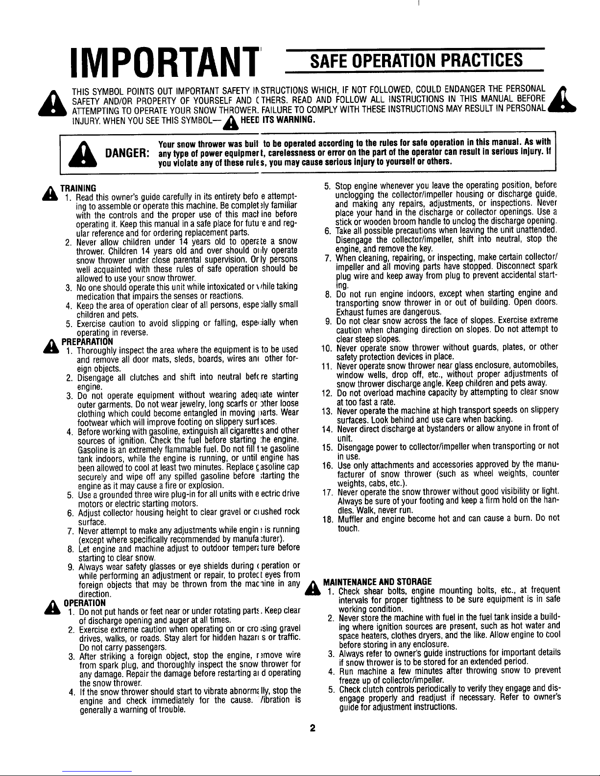
IMPORTANT
SAFEOPERATIONPRACTICES
THIS SYMBOLPOINTSOUT IMPORTANTSAFETYI1_STRUCTIONSWHICH, IF NOT FOLLOWED,COULDENDANGERTHEPERSONAL_
SAFETYAND/OR PROPERTYOF YOURSELFAND CTHERS. READAND FOLLOWALL INSTRUCTIONSIN THIS MANUAL BEFORE
ATTEMPTINGTOOPERATEYOURSNOWTHROWER•FAILURETOCOMPLYWITH THESEINSTRUCTIONSMAY RESULTIN PERSONAL,
INJURY.WHENYOUSEETHIS SYMBOL-- _IL HEEDITS WARNING.
,_ Yoursnowthrowerwas bull to be operatedaccordingto the rules for safe operation in this manual. As with [
m
DANGER: any type ofpowerequipmert, carelessnessor erroron the part of the operatorcan result in seriousinjury, if
Iyou violate any of these rules, you may causeseriousinjury to yourself or others.
TRAINING
1. Readthis owner's guide carefully in its entirety berg
ing to assemble or operatethis machine. Becomplet
with the controls and the proper use of this mact
operating it. Keepthis manual in a safe placefor futu
ular referenceand for ordering replacement parts.
2. Never allow children under 14 years old to oper;
thrower. Children 14 years old and over should ol
snow thrower under close parental supervision. Or
well acquainted with these rules of safe operation
allowed to useyour snow thrower.
3. No one should operatethis unit while intoxicatedor
medication that impairs the senses or reactions.
4. Keep the area of operation clear of all persons, espe
children andpets.
5. Exercise caution to avoid slipping or falling, espe_
operating in reverse.
_lb PREPARATION
1. Thoroughly inspect the areawhere the equipment is
and remove all door mats, sleds, boards, wires an_
eign objects.
2. Disengage all clutches and shift into neutral bef(
engine.
3. Do not operate equipment without wearing adeq_
outer garments. Do not wear jewelry, long scarfs or
clothing which could become entangled in moving I
footwear which will improve footing on slippery surf
4. Before working with gasoline, extinguish all cigarette
sources of ignition. Check the fuel before starting
Gasolineis an extremely flammable fuel. Do not fill
tank indoors, while the engine is running, or until
beenallowed to cool at leasttwo minutes. Replace
securely and wipe off any spilled gasoline before
engineas it maycause a fire or explosion.
5. Usea grounded three wire plug-in for all units with e
motors or electric starting motors.
6. Adjust collector housing height to clear gravel or cM
surface.
7. Neverattempt to make any adjustments while engin
(except where specifically recommended by manufa
8. Let engine and machine adjust to outdoor temper_
starting to clear snow.
9. Always wear safety glasses or eye shields during
while performing an adjustment or repair,to protec
foreign objects that may be thrown from the mac
direction.
OPERATION
1. Donot put hands or feet near or under rotating part,,
of discharge opening and augerat all times•
2. Exerciseextreme caution when operating on or cro
drives, walks, or roads. Stay alert for hidden hazan
Do not carry passengers.
3. After striking a foreign object, stop the engine,
from spark plug, and thoroughly inspect the snow
any damage. Repairthe damagebefore restarting a_
the snow thrower.
4. Ifthe snow thrower should start to vibrate abnorm_
engine and check immediately for the cause.
generally a warning of trouble.
eattempt-
,flyfamiliar
ine before
e andreg-
te a snow
tly operate
ly persons
shouldbe
rhiletaking
"iallysmall
;iallywhen
tobe used
otherfop
re starting
latewinter
)therloose
)arts.Wear
ices.
sandother
:heengine.
1le gasoline
enginehas
asolinecap
;tartingthe
ectric drive
ushedrock
_isrunning
:turer).
ture before
( perationor
teyesfrom
_mein any
•Keepclear
;singgravel
s or traffic.
r,'move wire
thrower for
doperating
Ily, stop the
/ibration is
5. Stop enginewheneveryouleavethe operatingposition,before
uncloggingthe collector/impellerhousingor dischargeguide,
and makingany repairs,adjustments,or inspections.Never
placeyour handin the dischargeor collectoropenings.Usea
stickorwoodenbroomhandleto unclogthe dischargeopening.
6. Takeallpossibleprecautionswhenleavingtheunitunattended.
Disengagethe collector/impeller,shift into neutral,stop the
engine,andremovethekey.
7. Whencleaning,repairing,or inspecting,makecertaincollector/
impellerandall movingpartshavestopped.Disconnectspark
plugwireandkeepawayfrom plugto preventaccidentalstart-
ing.
8. Do not run engineindoors,exceptwhenstartingengineand
transportingsnowthrower in or out of building.Opendoors.
Exhaustfumesaredangerous.
9. Do not clearsnowacrossthe faceof slopes.Exerciseextreme
cautionwhenchangingdirectionon slopes.Donotattemptto
clearsteepslopes.
10. Neveroperatesnowthrower withoutguards,plates,or other
safetyprotectiondevicesin place.
11. Neveroperatesnowthrowernearglassenclosure,automobiles,
window wells, drop off, etc., without properadjustmentsof
snowthrowerdischargeangle.Keepchildrenandpetsaway.
12. Do not overloadmachinecapacitybyattemptingto clearsnow
attoo fasta rate.
13. Neveroperatethemachineathightransportspeedsonslippery
surfaces.Lookbehindandusecarewhenbacking.
14. Neverdirectdischargeatbystandersorallowanyonein frontof
unit.
15. Disengagepowertocollector/impellerwhentransportingor not
inuse.
16. Useonly attachmentsandaccessoriesapprovedbythe manu-
facturer of snow thrower (such as wheel weights,counter
weights,cabs,etc.).
17. Neveroperatethesnowthrowerwithoutgoodvisibilityor light.
Alwaysbesureof yourfootingandkeepafirm holdonthehan-
dles.Walk,neverrun.
18. Mufflerand enginebecomehot andcan causea burn. Do not
touch.
,_ MAINTENANCEAND STORAGE
1. Check shear bolts, engine mounting bolts, etc., at frequent
intervalsfor propertightness to be sure equipmentis in safe
workingcondition.
2. Neverstorethe machine withfuel inthe fueltank insidea build-
ingwhere ignitionsources are present,such as hot water and
spaceheaters,clothesdryers,and thelike.Allow engineto _:ool
beforestoringin any enclosure.
3. Always referto owner's guide instructionsfor importantdetails
if snowthroweris to be storedfor an extendedperiod.
4. Run machine a few minutes after throwing snow to prevent
freezeup ofcollector/impeller.
5. Check clutchcontrolsperiodicallyto verify they engage and dis-
engage properly and readjust if necessary.Refer to owner's
guidefor adjustmentinstructions.
Page 3
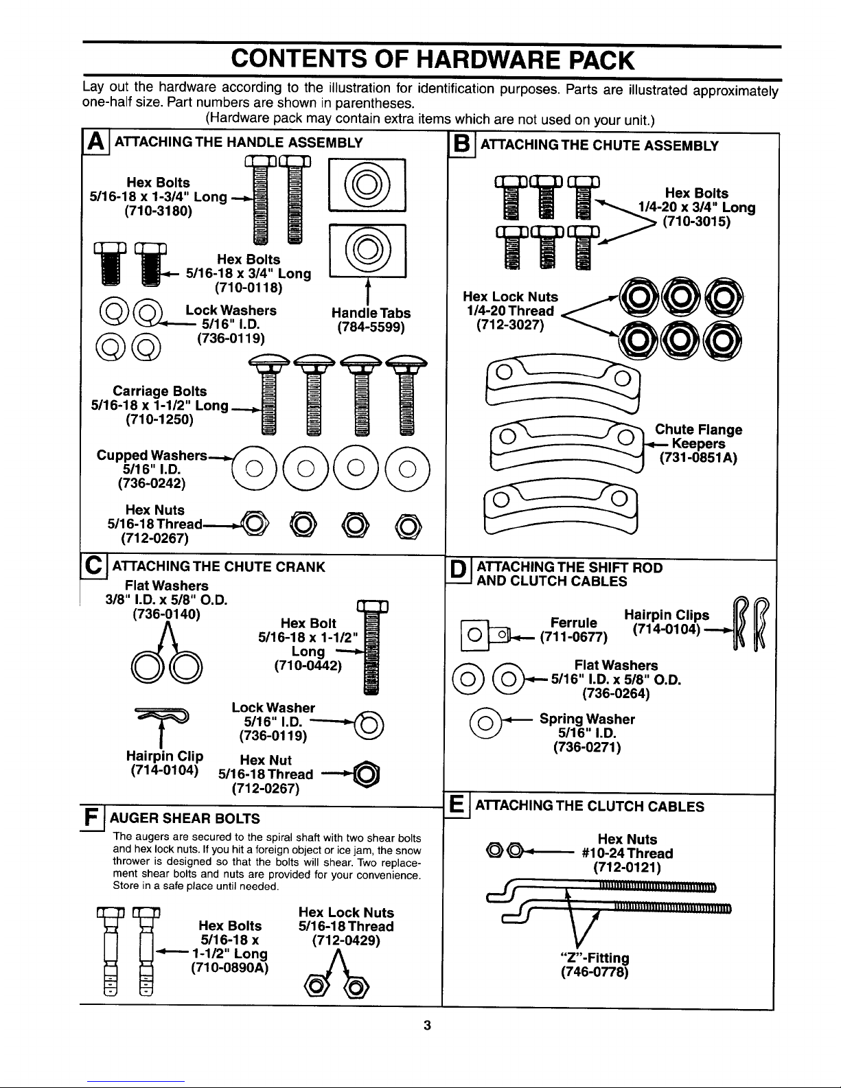
CONTENTS OF HARDWARE PACK
Lay out the hardware according to the illustration for identification purposes. Parts are illustrated approximately
one-half size. Part numbers are shown in parentheses.
(Hardware pack may contain extra items which are not used on your unit.)
A_ ATTACHING THE HANDLE ASSEMBLY
Hex Bolts [
5/16-18 x 1-3/4" Long
(710-3180)
[__ Hex Bolts
5116-18 x 3/4" Long
(710-0118)
(_(_ Lock Washers
5/16" I.D.
(_(_ (736-0119)
Carriage Bolts
5/16-18 x 1-1/2" Long
(710-1250)
@1
@
f
Handle Tabs
(784-5599)
Cupped Washers_
5/16" I.D. _ _
(736-0242) _._.j'
Hex Nuts
5/16-18 Thread-_,._ @
(712-0267)
C JATrACHING THE CHUTE CRANK
Flat Washers
318" I.D. x 518" O.D.
Hex Bolt
5/16-18 x 1-1/2"
Long
(710-0442)
Lock Washer
5116" I.D.
(736-0119)
Hairpin Clip Hex Nut
(714-0104) 5/16-18 Thread --_
(712-0267)
F.__ AUGER SHEAR BOLTS
The augers are secured to the spiral shaft with two shear bolts
and hex lock nuts. If you hit a foreign object or ice jam, the snow
thrower is designed so that the bolts will shear. Two replace-
ment shear bolts and nuts are provided for your convenience.
Store in a safe place until needed.
_ _.,_._ Hex Bolts
5/16-18 x
1-1/2" Long
(710-0890A)
Hex Lock Nuts
5/16-18 Thread
(712-0429)
S I ATTACHING THE CHUTE ASSEMBLY
TTT .exoo,,.
1/4-20 x 3/4" Long
TT T _ (710-3015)
Hex Lock Nuts.@@ @
1/4-20 Thread
@@@
ute Flange
Keepers
31-0851A)
D I ATTACHING THE SHIFT ROD
AND CLUTCH CABLES
Ferrule
(711-0677)
Hairpin Clips ['_
(714-0104) ---_
(_(_ Flat Washers
5/16" I.D. x 5/8" O.D.
(736-0264)
(_ Spring Washer
5/16" I.D.
(736-0271)
E__ ATTACHING THE CLUTCH CABLES
Hex Nuts
_ _ #10-24 Thread
(712-0121)
• V ""_'""""m"I_"""m'_l_
"Z'-Fitting
(746-0778)
Page 4
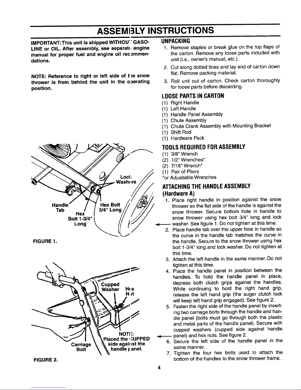
ASSEMI3LY INSTRUCTIONS
IMPORTANT: This unit is shipped WITHOU'" GASO-
LINE or OIL. After assembly, see separab_ engine
manual for proper fuel and engine oil rec:_mmen-
dations.
NOTE: Reference to right or left side of tile snow
thrower is from behind the unit in the operating
position.
Handle
Tab
Hex
Bolt 1-3/4"
Long
FIGURE 1.
Cupped
Washer Hq:x
N_it
FIGURE 2.
Carriage
Bolt
NOTI ":
Placed the q_UPPED
side agail _st the
handle _anel.
UNPACKING
1. Remove staples or break glue on the top flaps of
the carton. Remove any loose parts included with
unit (i.e., owner's manual, etc.).
2. Cut along dotted lines and lay end of carton down
flat. Remove packing material.
3. Roll unit out of carton. Check carton thoroughly
for loose parts before discarding.
LOOSE PARTS IN CARTON
(1) Right Handle
(1) Left Handle
(1) Handle Panel Assembly
(1) Chute Assembly
(1) Chute Crank Assembly with Mounting Bracket
(1) Shift Rod
(1) Hardware Pack
TOOLS REQUIRED FOR ASSEMBLY
(1) 3/8" Wrench
(2) 1/2" Wrenches*
(2) 7/16" Wrench*
(1) Pair of Pliers
*or Adjustable Wrenches
ATTACHINGTHE HANDLEASSEMBLY
(HardwareA)
1. Place right handle in position against the snow
thrower so the flat side of the handle is against the
snow thrower. Secure bottom hole in handle to
snow thrower using hex bolt 3/4" long and lock
washer. See figure 1. Do not tighten at this time.
Place handle tab over the upper hole in handle so
the curve in the handle tab matches the curve in
the handle. Secure to the snow thrower using hex
bolt 1-3/4" long and lock washer. Do not tighten at
this time.
3. Attach the left handle in the same manner. Do not
tighten at this time.
4. Place the handle panel in position between the
handles. To hold the handle panel in place,
depress both clutch grips against the handles.
While continuing to hold the right hand grip,
release the left hand grip (the auger clutch lock
will keep left hand grip engaged). See figure 2.
5. Fasten the right side of the handle panel by insert-
ing two carriage bolts through the handle and han-
dle panel (bolts must go through both the plastic
and metal parts of the handle panel). Secure with
cupped washers (cupped side against handle
panel) and hex nuts. See figure 2.
Secure the left side of the handle panel in the
same manner.
7. Tighten the four hex bolts used to attach the
bottom of the handles to the snow thrower frame.
4
Page 5
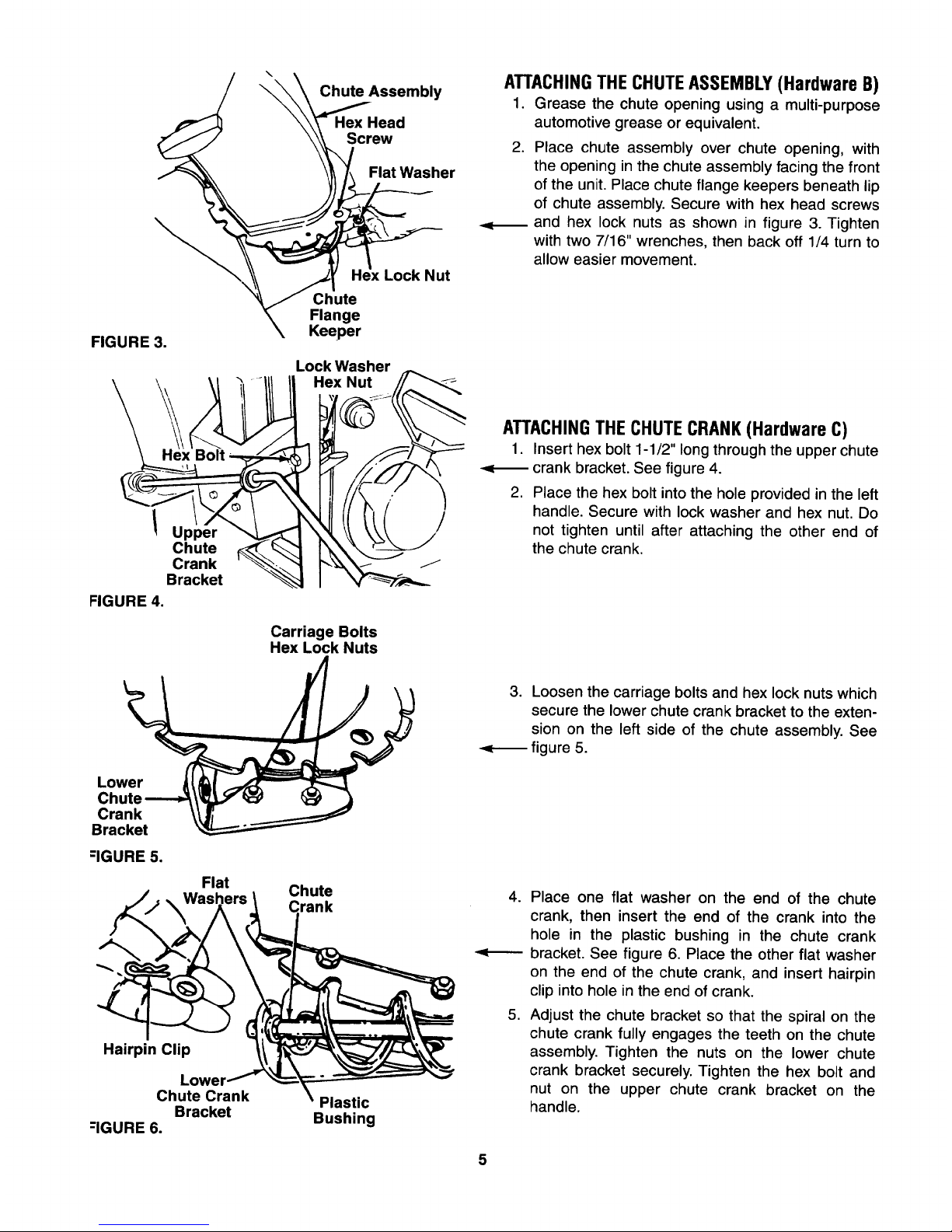
FIGURE 3.
\
Chute Assembly
Hex Head
Screw
Flat Washer
Lock Nut
Chute
Flange
Keeper
Lock Washer
Hex Nut
_m
ATTACHINGTHE CHUTEASSEMBLY(Hardware B)
1. Grease the chute opening using a multi-purpose
automotive grease or equivalent.
.
Place chute assembly over chute opening, with
the opening in the chute assembly facing the front
of the unit. Place chute flange keepers beneath lip
of chute assembly. Secure with hex head screws
and hex lock nuts as shown in figure 3. Tighten
with two 7/16" wrenches, then back off 1/4 turn to
allow easier movement.
Upper
Chute
Crank
Bracket
FIGURE 4.
Carriage Bolts
Hex Lock Nuts
ATTACHINGTHE CHUTECRANK (Hardware C)
1. Insert hex bolt 1-1/2" long through the upper chute
-<_ crank bracket. See figure 4.
2. Place the hex bolt into the hole provided in the left
handle. Secure with lock washer and hex nut. Do
not tighten until after attaching the other end of
the chute crank.
Lower
Chute
Crank
Bracket
-IGURE 5.
Flat
Hairpin Clip
Lower
Chute Crank
Bracket
--IGURE 6.
Chute
rank
Plastic
Bushing
3. Loosen the carriage bolts and hex lock nuts which
secure the lower chute crank bracket to the exten-
sion on the left side of the chute assembly. See
figure 5.
4. Place one flat washer on the end of the chute
crank, then insert the end of the crank into the
hole in the plastic bushing in the chute crank
bracket. See figure 6. Place the other flat washer
on the end of the chute crank, and insert hairpin
clip into hole in the end of crank.
5. Adjust the chute bracket so that the spiral on the
chute crank fully engages the teeth on the chute
assembly. Tighten the nuts on the lower chute
crank bracket securely. Tighten the hex bolt and
nut on the upper chute crank bracket on the
handle.
5
Page 6

IMPORTANT:Attachthe shift rod andcl itch cables as follows. THEN CHECK THE ADJUSTMENTS AS
INSTRUCTED, AND MAKE ANY FINAL A[)JUSTMENTS NECESSARY BEFORE OPERATING YOUR SNOW
THROWER. Failure to follow the instructi,)ns may cause damage to the snow thrower.
Tracti°_ hiftClutchDrive Lever
I1 Washer Fer u e
J/Shift
1Arm
_ssembly
ATTACHINGTHE SHIFT ROD (Hardware D)
1. Place the shift lever (on the handle panel) in the
sixth (6) speed position (all the way forward).
Place the bent end of the shift rod into the hole in
the shift arm assembly. See figure 7. Secure with
spring washer, flat washer and hairpin clip.
3. Start threading the ferrule onto the other end of the
shift rod. Push down on the shift rod (and shift arm
assembly) as far as it will go.
4. Thread the ferrule onto the shift rod until the ferrule
lines up with the upper hole in the shift lever
(beneath the handle panel). Insert the ferrule into
the upper hole in the shift lever from the left side
when adjustment is correct. Secure with flat
washer and hairpin clip.
Make certain to check for correct adjustment of the
shift rod as instructed in the Final Adjustment section
before operating the snow thrower.
FIGURE 7.
Hex Jam
Nut
/
/
Cable is Strai
FIGURE 8.reViewed from Underside of H_nndle
Panel
ATTACHINGTHE CLUTCH CABLES(Hardware E)
The "Z" end of the clutch cables are hooked into the
clutch grips on each handle. Attach cables as follows.
1. Thread the hex nuts (in hardware pack) all the
way up the threaded portion of the "Z" ends of the
clutch cables.
2. Make certain each cable is in groove of cable
roller guides. Place the clutch grip in the raised
(up) position.
3. Thread the cable onto the threaded portion of the
"Z" end until there is no slack in the cable, but the
cable is NOT tight. Do not overtighten cable.
See figure 8.
&
WARNING: If cable is tightened so there is
tension on the cable with the clutch grip
released, the safety features of the snow
thrower may be overridden.
4. When correct adjustment is reached, tighten the
hex nut against the bottom portion of the cable to
lock it in position.
FINAL ADJUSTMENTS
Auger Drive Clutch
To check the adjustment of the auger drive clutch,
push forward on the left hand clutch grip (depress the
rubber bumper). There should be slack in the cable.
Release the clutch grip. The cable should be straight.
Make certain you can depress the auger drive clutch
grip against the left handle completely.
Page 7

If necessary,loosenthe hexjamnutandthreadthe
cablein(forlessslack)orout(formoreslack)asnec-
essary.Referto figure8. Recheckthe adjustment.
Tightenthejam nutagainstthe cablewhencorrect
adjustmentisreached.
Traction Drive Clutch and Shift Lever Adjustment
To check the adjustment of the traction drive clutch
and shift lever, tip the snow thrower forward so that it
rests on the auger housing. First move the shift lever
all the way forward to sixth (6) position. With the trac-
tion drive lever released, spin the snow thrower wheels
by hand. They should turn freely. Then engage the
traction drive clutch grip. The wheels should stop turn-
ing.
Now release the traction drive clutch grip, and spin the
wheels again. Move the shift lever back to the fast
reverse position, then all the way forward again. There
should be no resistance in the shift lever, and the
wheels should keep turning.
If you have resistance when moving the shift lever or
the wheels stop when they should not, loosen the jam
nut on the traction drive cable and unthread the cable
one turn. If the wheels do not stop when you engage
the traction drive clutch grip, loosen the jam nut on the
traction drive cable and thread the cable in one turn.
Recheck the adjustment and repeat adjustment as
necessary. Tighten the jam nut to secure the cable
when correct adjustment is reached.
NOTE: If you are uncertain that you have reached the
correct adjustment, refer to the Adjustment section on
page 10.
ADJUSTING THE SKID SHOES
The space between the shave plate and the ground
can be adjusted. For close snow removal, place skid
shoes in the low position. Use middle or high position
when area to be cleared is uneven. See figure 9.
Adjust skid shoes by loosening the four hex nuts and
carriage bolts and moving skid shoes to desired posi-
tion. Make certain the entire bottom surface of skid
shoe is against the ground to avoid uneven wear on
the skid shoes. Retighten nuts and bolts securely.
It is not recommended that you operate this snow
thrower on gravel as loose gravel can be easily picked
up and thrown by the auger causing an injury or dam-
age to the snow thrower.
Skid
Shoe
FIGURE 9.
uts
Carriage Bolts
TIREPRESSURE(PneumaticTires)
The tires are over-inflated for shipping purposes.
Check tire pressure and reduce to 15 to 20 psi.
NOTE: If the tire pressure is not equal in both tires, the
un# may pull to one side or the other.
Auger
Drive
CONTROLS
Traction
Drive/
Auger
Clutch
Lock
SHIFT LEVER
(See figures 10 and 11)
The shift lever is located in the center of
the handle panel. The shift lever may be
moved into one of eight positions. Run
engine with throttle in the fast position.
Use the shift lever to determine ground
speed.
Forwardmone of six speeds. Position
number one (1) is the slowest. Position
number six (6) is the fastest.
FIGURE 10.
7
Reverse--two reverse (R) speeds. "R"
closest to the operator (all the way
back) is the faster of the two.
FIGURE 11.
Page 8

AUGER DRIVE (See figure 10)
The auger drive clutch is located on the let handle.
Squeeze the clutch grip to engage the augers.
Release to stop the snow throwing action. (Traction
drive clutch must also be released.)
TRACTIONDRIVE/AUGERCLUTCHLOCK
(See figure 10)
The traction drive clutch is located on the rigl _thandle.
Squeeze the traction drive clutch to engage'he wheel
drive. Release to stop.
This same lever also locks the auger clutch s,) you can
turn the chute crank without interrupting he snow
throwing process. If the auger drive clutch is engaged
with the traction drive clutch engaged, the operator
can release the auger drive clutch (on the le :t handle)
and the augers will remain engaged. Releas_ the trac-
tion drive clutch to stop both the augers a_d wheel
drive (auger drive clutch must also be releasl _d).
CHUTE CRANK(See figure 10)
The chute crank is located on left hand si Je of the
snow thrower.
To change the direction in which snow is thr _wn, turn
chute crank as follows:
1. Crank clockwise to discharge to the left.
2. Crank counterclockwise to discharge to l he right.
THROTTLE CONTROL(See figure 12)
The throttle control is located on the engin_. It regu-
lates the speed of the engine.
SAFETYIGNITIONSWITCH(see figure12)
The ignition key must be inserted in the switch before
the unit will start. Remove the ignition key when snow
thrower is not in use.
FUELSHUT-OFFVALVE
The fuel shut-off valve,
located under fuel tank, con-
trols fuel flow from tank.
Choke
Primer
Ignition
Key
Throttle
Control
FIGURE 12.reModel 610E Shown
Starter
Handle
OPERATION
GASAND OIL FILL-UP
Service the engine with gasoline an J oil as
instructed in the separate engine manual p_cked with
your snow thrower. Read instructions care1 ully.
NOTE: Your snow thrower is shipped withoL t oil; how-
ever, a small amount of oil may be presen' from the
factory. Do not overfill.
_ WARNING: Never fill fuel tank indoors,
with engine running or while _;ngine is
hot. Do not smoke when filling ft el tank.
Electric Starter
WARNING: The electric starter is equipp_d with a
three-wire power cord and plug, and is d_signed to
operate on 120 volt AC household current. It must be
properly grounded at all times to avoid the 3ossibility
of electric shock which may be injurioLs to the
operator. Follow all instructions carefully. I)etermine
that your house wiring is a three-wire grounded
system. Ask a licensed electrician if yoL are not
certain. If your house wiring system is not a :hree-wire
grounded system, do not use this electric starter under
any conditions. If your system is grounded and a
three-hole receptacle is not available at the point your
starter will normally be used, one should be installed
by a licensed electrician.
When connecting the power cord, always connect cord
to switch box on engine first, then plug the other end
into a three-hole grounded receptacle.
When disconnecting the power cord, always unplug
the end from the three-hole grounded receptacle first.
TO STARTENGINE
IMPORTANT: If unit shows any sign of motion (drive or
augers) with the clutch grips disengaged, shut engine
off immediately. Readjust as instructed in the "Final
Adjustments" section of the Assembly Instructions.
1. Attach spark plug wire to spark plug.
2. Make certain the fuel shut-off valve is in the open
(vertical) position.
3. Make certain the auger drive and traction drive
clutch grips are in the disengaged (released)
position.
Page 9

4. Move throttle control up to FAST position. Insert
ignition key into slot. See figure 12. Be certain it
snaps into place. Do not turn key.
5. Rotate choke knob to FULL choke position (cold
engine start).
If engine is warm, place choke in OFF position
instead of FULL.
6. Connect power cord to switch box on engine. Plug
the other end of power cord into a three-hole,
grounded 120 volt AC receptacle.
7. Recoil Start Only: Push primer button two or
three times. If engine is warm, push primer button
once only. See figure 12.
NOTE: Always cover vent hole in primer button when
pushing. Adc/itiona/priming may be necessary for first
start if temperature is below 15°F.
8. Electric Start: Push starter button on top of the
switch box to crank the engine. When engine
starts, release starter button.
Recoil Start: Grasp starter handle (see figure 12)
and pull rope out slowly, until it pulls slightly
harder. Let rope rewind slowly. Pull starter handle
rapidly.Do not allow handle to snap back. Allow it
to rewind slowly while keeping a firm hold on the
starter handle.
9. Repeat step 8 until engine starts. If engine fails to
start, repeat steps 7 and 8 until engine starts.
10. As engine warms up and begins to operate evenly,
rotate choke knob slowly to OFF position. If
engine falters, return to FULL choke, then slowly
move to OFF position.
Electric Starter: Connect power cord to switch box on
engine, then to 120 volt AC receptacle. With the
engine running, push starter button and spin the
starter for several seconds. The unusual sound made
by spinning the starter will not harm engine or starter.
Disconnect the power cord from receptacle first, and
then from switch box.
Recoil Starter (Optional Instructions): With engine
running, pull starter rope with a rapid, continuous full
arm stroke three or four times. Pulling the starter rope
will produce a loud clattering sound, which is not
harmful to the engine or starter.
3. To stop engine, remove the ignition key. Do not
turn key. Disconnect the spark plug wire from the
spark plug to prevent accidental starting while
equipment is unattended.
NOTE: Do not lose ignition key. Keep it in a safe place.
Engine will not start without the ignition key.
4. Wipe all snow and moisture from the carburetor
cover in the area of the control levers. Also, move
control levers back and forth several times. Leave
throttle control lever in the STOP or OFF position.
Leave choke control in the FULL choke position.
AVOIDINJURYFROM ROTATING
AUGERm KEEPHANDS, FEET
ANDCLOTHINGAWAY. s7as
TO STOP ENGINE
1. Run engine for a few minutes before stopping to
help dry off any moisture on the engine.
2. To help prevent possible freeze-up of starter, pro-
ceed as follows.
TO ENGAGEDRIVE
1. With the engine running near top speed, move
shift lever into one of the six FORWARD positions
or two REVERSE positions. Select a speed
appropriate for the snow conditions that exist. Use
the slower speeds until you are familiar with the
operation of the snow thrower.
2. Squeeze the traction drive clutch grip against the
right handle and the snow thrower will move.
Release it and the drive motion will stop.
NOTE: NEVER move shift lever without first releasing
the drive clutch.
TO ENGAGEAUGERS
To engage the augers and start the snow throwing
action, squeeze the auger clutch grip against the left
handle. Release to stop the augers (traction drive
clutch grip must also be released).
The auger drive clutch can also be locked so you can
turn the chute crank without interrupting the snow
throwing process. Refer to "Traction Drive/Auger
Clutch Lock" in the Control section.
9
Page 10

TIRECHAINS(OptionalEquipment)
Tire chains should be used whenever extra t'action is
needed.
OPERATINGTIPS
NOTE: Allow the engine to warm up for a fev, minutes
as the engine will not develop full pow6r until it
reaches operating temperature.
_ WARNING: Temperature of muf:ler and
surrounding areas may exceecl 150°1=.
Avoid these areas.
1. For most efficient snow removal, rem<_ve snow
immediately after it falls.
2. Discharge snow downwind whenever possible.
Slightly overlap each previous swath.
3. Set the skid shoes 1/4" below the scrap,=r bar for
normal usage. The skid shoes may be adjusted
upward for hard-packed snow. If you (hoose to
use this snow thrower on gravel or crus ned rock,
adjust the skid shoes downward and us e caution
to avoid picking up gravel or rock with 1he shave
plate or augers.
4. Be certain to follow the precautions lised under
"To Stop Engine" on page 9 to preven possible
freeze-up.
5. Clean the snow thrower thoroughly after each
use.
ADJUSTMENTS
_1) WARNING: NEVER attempt to cle an chute
or make any adjustments while, mgine is
running.
CHUTEASSEMBLYADJUSTMENT
The distance snow is thrown can be acjusted by
adjusting the angle of the chute assembly. TPe sharper
the angle, the shorter the distance snow s thrown.
See figure 13.
To adjust chute assembly, loosen the hand _nob. Pivot
the top of the chute assembly to position1 desired.
Retighten the hand knob.
FIGURE 13.
Hand
Knob
SKIDSHOEADJUSTMENT
The space between the shave plate and the ground
can be adjusted. Refer to page 7 of the Assembly
Instructions.
TRACTION DRIVE CLUTCH ADJUSTMENT
Refer to the Final Adjustment section of the Assembly
Instructions to adjust the traction drive clutch. If you
are uncertain that you have reached the correct
adjustment, the adjustment can be physically checked
as follows.
With the snow thrower tipped forward (be certain to
drain the gasoline or place plastic film under the gas
cap if the snow thrower has already been operated),
remove the frame cover underneath the snow thrower
by removing six self-tapping screws.
With the traction drive clutch released, there must be
clearance between the friction wheel and the drive
plate in all positions of the shift lever. With the traction
drive clutched engaged, the friction wheel must con-
tact the drive plate. See figure 14.
If adjustment is necessary, loosen the jam nut on the
traction drive cable and thread the cable in or out as
necessary. Tighten the jam nut to secure the cable
when correct adjustment is reached. Reassemble the
frame cover.
NOTE: If you placed plastic under the gas cap, be cer-
tain to remove it.
.r,c.,on
Ij_II ._ Wheel
ve____ '-_
,r'te
t
FIGURE 14.
m
B
AUGERCLUTCH ADJUSTMENT
To adjust the auger clutch, refer to Final Adjustment
section of Assembly Instructions.
SHIFT ROD ADJUSTMENT
To adjust the shift rod, separate the shift rod and fer-
rule from the shift lever by removing the hairpin clip
and flat washer from the ferrule underneath the handle
panel. Refer to figure 7. Adjust as specified in the
Assembly Instructions.
10
Page 11

CARBURETORADJUSTMENT
_ WARNING: If any adjustments are made to
the engine while the engine is running
(e.g. carburetor), keep clear of all moving
parts. Be careful of heated surfaces and
muffler.
Minor carburetor adjustment may be required to com-
pensate for differences in fuel, temperature, altitude
and load.
Refer to the separate engine manual packed with your
unit for carburetor adjustment information.
DRIVE WHEELS
The wheels may be adjusted for two different methods
of operation. The adjustment is made by placing the
klick pins in one of two different holes on the right side
of the unit. See figure 15.
1. One Wheel DrivingmPlace klick pin in the out-
side axle hole on the right side. This position gives
power drive to the left wheel only, making the unit
easier to maneuver.
,
Both Wheels Driving--Place klick pin in the hole
in the hub next to the rim on the right side. This
position is good for heavy snow as there is power
drive in both wheels.
WHEELS
Oil or spray lubricant into wheel bearings at least once
a season. Remove wheels, clean and coat axles with a
multi-purpose automotive grease. See figure 16.
Oil Bearings
or Spray Lubricant
FIGURE 16.
CHUTE CRANK
The gear on the end of the chute crank should be
greased with multi-purpose automotive grease once a
season.
AUGERSHAFT
At least once a season, remove shear bolts on auger
shaft. Oil or spray lubricant inside shaft. See figure 17.
Also lubricate the auger bearings at least once a
season.
Outside Hole
in Axle
FIGURE 15.
LUBRICATION
_b) WARNING: Disconnect the spark plug
wire and ground against the engine
before performing any lubrication or
maintenance.
ENGINE
Refer to engine manual for all engine lubrication
instructions.
_ WARNING: When following instructions in
separate engine manual for draining oil,
be sure to protect frame to avoid oil
dripping onto transmission parts.
Shear Bolts
FIGURE 17.
Bearings
GEARSHAFT
Lubricate the gear shaft with "Slick 50 Grease" at least
once a season or after every 25 hours of operation
(available at automotive stores, or order part number
737-0290). Refer to figure 14.
IMPORTANT: Keep all grease and oil off of the
rubber friction wheel and aluminum drive plate.
11
Page 12

DRIVEANDSHIFTINGMECHANISM
At least once a season or after every 25 h(urs of
operation, remove rear cover. Lubricate any gears,
bearings, shafts, and shifting mechanism at lea.,_tonce
a season. Use engine oil or a spray lubricant. Avoid
getting oil on rubber friction wheel and aluurdnum
drive plate. Refer to figure 14.
TRACTIONDRIVE/AUGERCLUTCHLOCK
The cams on the ends of the control rods whicll inter-
lock the traction drive and auger drive clutche _ must
be lubricated at least once a season or every lwenty-
five hours of operation, The cams can be acq'essed
beneath the handle panel. Use a multi-purposq; auto-
motive grease,
GEAR CASE
The gear case is lubricated with grease at the Factory
and does not require checking. If disassembled Forany
reason, lubricate with 2 ounces of Shell _klvania
grease EPR00, part number 737-0168. Before
reassembling, remove old sealant and apply 'Loctite
5699" or equivalent.
IMPORTANT: Do not overfill the gear _=ase.
Damage to the seals could result. Be sur,,_the
vent plug is free of grease in order to r_lieve
pressure.
To remove shave plate, remove the carriage bolts,
belleville washers and hex nuts which attach it to the
snow thrower housing. Reassemble new shave plate,
making sure heads of the carriage bolts are to the
inside of the housing. Tighten securely.
ENGINE
Refer to separate engine manual for all engine mainte-
nance procedures.
BELTREMOVAL AND REPLACEMENT
,_WARNING: Disconnect the sparkwire from the spark plug and ground.
plug
AUGERBELTS
NOTE: It is necessary to remove both belts in order to
change either one. If changing just one belt, be certain
to check the condition of the other belt (model 610E
has only one auger belt).
1. Remove the plastic belt cover on the front of the
engine by removing the two self-tapping screws.
See figure 18.
MAINTENANCE
AUGERS
The augers are secured to the spiral shaft with two
shear bolts and hex lock nuts. See figure 17. If you hit
a foreign object or ice jam, the snow thrcwer is
designed so that the hex bolts will shear.
If the augers will not turn, check to see if the bol :s have
sheared. Two replacement shear bolts and h ,_xlock
nuts have been provided with the snow thrower. For
future use, order part number 710-0890 (shear bolt
5/16-18 x 1.5" long) and 712-0429 (hex insert I)ck nut
5/16-18 thread).
SHAVEPLATEAND SKID SHOES
The shave plate and skid shoes on the botton_ of the
snow thrower are subject to wear. They sheuld be
checked periodically and replaced when neces:;ary.
To remove skid shoes, remove the four carriag .=bolts,
belleville washers and hex nuts which attach Inem to
the snow thrower. Reassemble new skid sho ,_swith
the four carriage bolts, belleville washers (cupp.=d side
goes against skid shoes) and hex nuts. Make certain
the skid shoes are adjusted to be level.
12
Belt Self-Tapping
Cover Screws
FIGURE 18.
2. Drain the gasoline from the snow thrower, or place
a piece of plastic under the gas cap.
3. Tip the snow thrower up and forward so that it
rests on the housing.
4. Remove six self-tapping screws from the frame
cover underneath the snow thrower.
5. Roll the front and rear auger belts off the engine
pulley. See figure 19.
Page 13

Rear
Auger
Drive
Belt
Englne
lulley
Front
Auger
Belt
Friction
Wheel
Engine
Pulley
Pulley Idler
Pulley
FIGURE 19.
Support
Bracket
Rear
Auger
Belt
Frame
6. Unhook the idler spring from the hex bolt on the
auger housing. See figure 20.
7. Back out the stop bolt to allow the belts to slip
between the bolt and auger pulley. See figure 21.
NOTE: It may be necessary to loosen the six hex nuts
that fasten the frame to the auger housing to aid in belt
removaL
8. Lift the rear auger belt from the auger pulley, and
slip belt between the support bracket and the
auger pulley. See figure 20. Repeat this step for
front auger belt (except model 610E).
9. Replace both auger drive belts by following
instructions in reverse order.
DRIVE BELT
1. Follow steps 1 through 4 of previous instructions.
2. Pull idler pulley up, and lift belt off engine pulley
and friction wheel disc. See figure 19.
3. Back out the stop bolt until the support bracket
rests on the auger pulley. See figure 21.
4. Slip belt between friction wheel and friction wheel
disc. See figure 21. Remove and replace belt.
Reassemble following the instructions in reverse
order.
NOTE: The support bracket must rest on the stop bolt
after the new belt has been assembled. See figure 21.
Auger
Pulley
Pulley
FIGURE 20.
Idler
Spring
Auger
Houslng
Bracket
Spring
Friction
Wheel
i D Bolt
FIGURE 21.
\
CHANGINGTHEFRICTIONWHEELRUBBER
The rubber on the friction wheel is subject to wear and
should be checked after 25 hours of operation, and
periodically thereafter. Replace the friction wheel
rubber if any signs of wear or cracking are found.
1. Drain the gasoline from the snow thrower, or place
a piece of plastic under the gas cap.
2. Tip the snow thrower up and forward, so that it
rests on the housing.
13
Page 14

3. Removesixself-tappingscrewsfromthe frame
coverunderneaththesnowthrower.
4. Removetheklickpinswhichsecurethev'heels,
andremovethewheelsfromtheaxle.
5. Usinga 7/8"wrenchtoholdtheshaft,Ioos,,=n,but
do not completelyremove,the hexnutal_dbell
washerontheleftendofgearshaft.Seefigure
22.
6. LightlytapthehexnuttodislodgetheballLearing
from the right side of frame. Remove the tex nut
and bell washer from left end of shaft.
7. Slide the gear shaft to the right and slide t_e fric-
tion wheel assembly from the shaft.
8. Remove the six screws from the friction wheel
assembly (three from each side). Remove t 7e fric-
tion wheel rubber from between the frictior wheel
plate.
9. Reassemble new friction wheel rubber to the
friction wheel assembly, tightening the six _crews
in rotation and with equal force.
10. Position the friction wheel assembly up o,_to the
pin of the shift rod assembly, and slide th,_ shaft
through the assembly. Reassemble in _everse
order.
FIGURE 22.
If unit is to be stored over 30 days, prepare for storage
as follows:
1. Remove all gasoline from carburetor and fuel tank
to prevent gum deposits from forming on these
parts and causing possible malfunction of engine.
a. Run engine until fuel tank is empty and engine
stops due to lack of fuel.
b. Drain carburetor by pressing upward on bowl
drain, located below the carburetor cover.
&
WARNING: Drain fuel into approved con-
tainer outdoors, away from open flame.
Be certain engine is cool. Do not smoke.
Fuel left in engine during warm weather
deteriorates and will cause serious start-
ing problems.
NOTE: Fuel stabilizer (such as STA-BIL) is an accept-
able alternative in minimizing the formation of fuel
gum deposits during storage. Add stabilizer to
gasoline in fuel tank or storage container. Always
follow mix ratio found on stabilizer container. Run
engine at least 10 minutes after adding stabilizer to
allow it to reach carburetor. Do not drain carburetor if
using fuel stabilizer.
2. Remove spark plug and pour one (1) ounce of
engine oil through spark plug hole into cylinder.
Crank engine several times to distribute oil.
Replace spark plug.
3. Remove all dirt from exterior of engine and equip-
ment.
4. Follow lubrication recommendations on page 11.
NOTE: When storing any type of power equipment in
an unventilated or metal storage shed, care should be
taken to rust proof the equipment. Using a light off or
silicone, coat the equipment, especially any chains,
springs, bearings and cables.
OFF-SEASON STORA(;E
&
WARNING: Never store engine with fuel in
tank indoors or in poorly ventilate(J areas,
where fuel fumes may reach ar open
flame, spark or pilot light as on a fl Jrnace,
water heater, clothes dryer or otl'er gas
appliance.
14
Page 15

TROUBLE SHOOTING GUIDE
Trouble
Engine fails to start
Engine runs erratic
Loss of power
Engine overheats
Excessive vibration
Hard to shift, or will
not shift
Unit fails to propel itself
Unit fails to discharge
snow
Possible Cause(s)
1. Fuel tank empty, or stale fuel.
2. Fuel shut-off valve closed.
3. Key not in switch on engine.
4. Spark plug wire disconnected.
5. Blocked fuel line.
6. Faulty spark plug.
1. Unit running on CHOKE.
2. Blocked fuel line or stale fuel.
3. Water or dirt in fuel system.
4. Carburetor out of adjustment.
1. Spark plug wire loose.
2. Gas cap vent hole plugged.
1. Engine oil level low.
2. Carburetor not adjusted properly.
Loose parts or damaged impeller.
Shift rod misadjusted.
1. Incorrect adjustment of drive clutch.
2. Drive belt loose or damaged.
1. Auger shear bolt broken.
2. Discharge chute clogged.
3. Foreign object lodged in auger.
4. Incorrect adjustment of auger drive
clutch.
5. Auger drive belt loose or damaged.
Corrective Action
1. Fill tank with clean, fresh gasoline.
2. Open shut-off valve.
3. Insert key.
4. Connect wire to spark plug.
5. Clean fuel line.
6. Clean, adjust gap or replace.
1. Turn choke knob to OFF position.
2. Clean fuel line; fill tank with clean
fresh gasoline.
3. Use carburetor bowl drain to drain
fuel tank. Refill with fresh fuel.
4. Adjust carburetor. See separate
engine manual.
1. Connect and tighten spark plug
wire.
2. Remove ice and snow from cap.
Be certain vent hole is clear.
1. Fill crankcase with proper oil.
2. Adjust carburetor. See separate
engine manual.
Stop engine immediately and
disconnect spark plug wire. Tighten
all bolts and nuts. Make all
necessary repairs. If vibration
continues, have unit serviced by
authorized service dealer.
Readjust shift rod. See Adjustment
section of this manual.
1. Adjust drive clutch. Refer to
Adjustment section.
2. Replace drive belt. Refer to
Maintenance section.
1. Replace auger shear bolt. Refer to
Maintenance section.
2. Stop engine immediately and
disconnect spark plug wire. Clean
discharge chute and inside of auger
housing.
3. Stop engine immediately and
disconnect spark plug wire.
Remove object from auger.
4. Adjust auger clutch. Refer to
Adjustment section.
5. Replace auger drive belt. Refer to
Maintenance section.
NOTE: For repairs beyond the minor adjustments listed above, please contact your nearest authorized service
dealer.
15
Page 16

Plate
_hoe
A
0
T
L
T
Page 17

_oriesor Service Information,
800-80017310
Model Number Serial Number
0000000000000000000000
Product Number
00000000000
May not fill all the above spaces
lhe only way to ensure the performance of your
product isto use original equipment parts and
.]ccessories. MTD designs and engineers quality
parts to exacting specifications. When you
substitute, you take a chance on quality,
reliability, safety and performance. Use MTD
original equipment,
the best buy on the American Landscape.
- American Made Ametlcan Owned I
 Loading...