

Yard Machines 317E660G000, 317E610E000, 317E640F000 Owner's Manual
OUTDOOR POWER EQUIPMENT
24", 26" and 28"
SNOW
THROWERS
Model Numbers
317E610E000
317E640F000
317E660G000
MTD PRODUCTS INC • P.O. BOX 368022 • CLEVELAND, OHIO 44136-9722
PRINTED IN U.S.A. FORM NO. 770-8782M
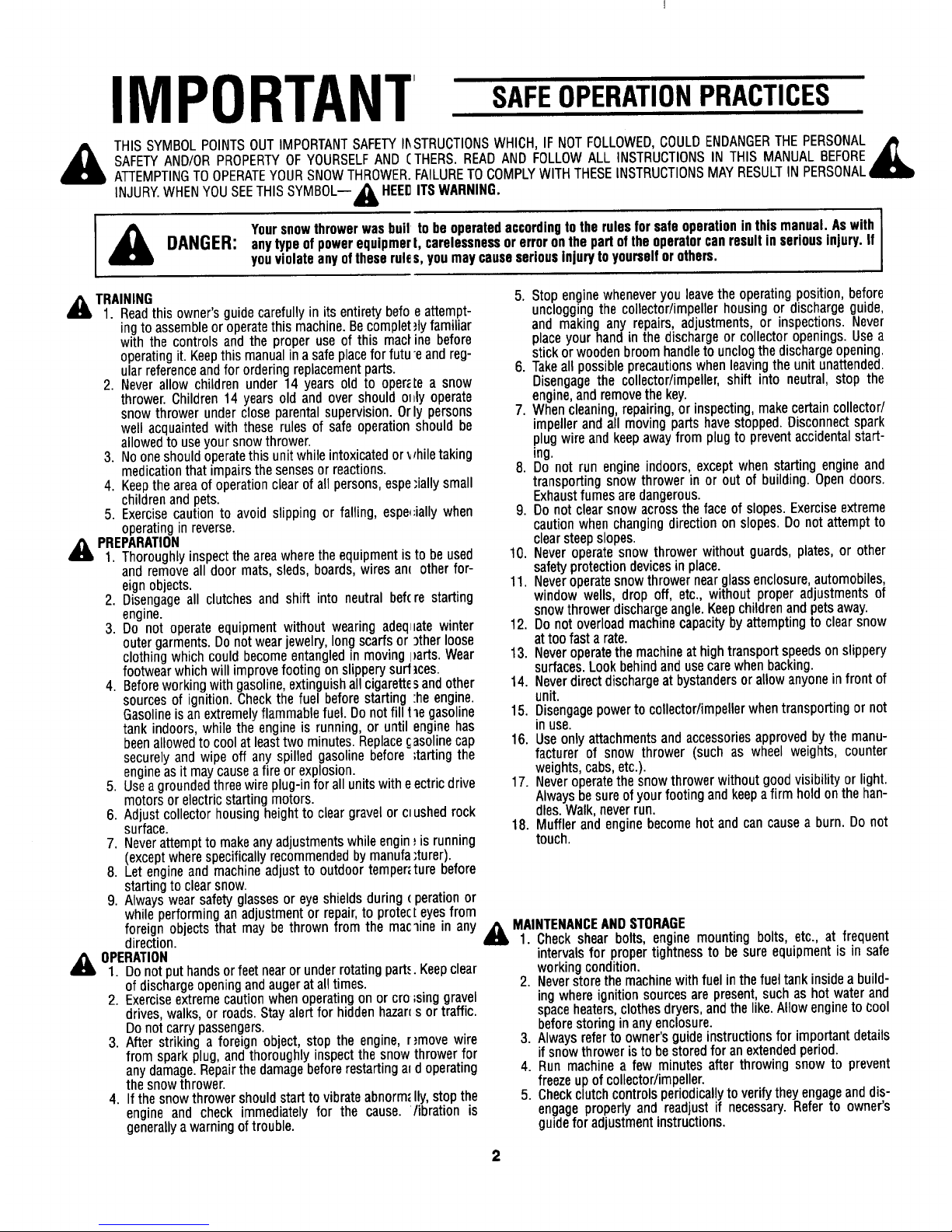
IMPORTANT
SAFEOPERATIONPRACTICES
THIS SYMBOLPOINTSOUT IMPORTANTSAFETYI1_STRUCTIONSWHICH, IF NOT FOLLOWED,COULDENDANGERTHEPERSONAL_
SAFETYAND/OR PROPERTYOF YOURSELFAND CTHERS. READAND FOLLOWALL INSTRUCTIONSIN THIS MANUAL BEFORE
ATTEMPTINGTOOPERATEYOURSNOWTHROWER•FAILURETOCOMPLYWITH THESEINSTRUCTIONSMAY RESULTIN PERSONAL,
INJURY.WHENYOUSEETHIS SYMBOL-- _IL HEEDITS WARNING.
,_ Yoursnowthrowerwas bull to be operatedaccordingto the rules for safe operation in this manual. As with [
m
DANGER: any type ofpowerequipmert, carelessnessor erroron the part of the operatorcan result in seriousinjury, if
Iyou violate any of these rules, you may causeseriousinjury to yourself or others.
TRAINING
1. Readthis owner's guide carefully in its entirety berg
ing to assemble or operatethis machine. Becomplet
with the controls and the proper use of this mact
operating it. Keepthis manual in a safe placefor futu
ular referenceand for ordering replacement parts.
2. Never allow children under 14 years old to oper;
thrower. Children 14 years old and over should ol
snow thrower under close parental supervision. Or
well acquainted with these rules of safe operation
allowed to useyour snow thrower.
3. No one should operatethis unit while intoxicatedor
medication that impairs the senses or reactions.
4. Keep the area of operation clear of all persons, espe
children andpets.
5. Exercise caution to avoid slipping or falling, espe_
operating in reverse.
_lb PREPARATION
1. Thoroughly inspect the areawhere the equipment is
and remove all door mats, sleds, boards, wires an_
eign objects.
2. Disengage all clutches and shift into neutral bef(
engine.
3. Do not operate equipment without wearing adeq_
outer garments. Do not wear jewelry, long scarfs or
clothing which could become entangled in moving I
footwear which will improve footing on slippery surf
4. Before working with gasoline, extinguish all cigarette
sources of ignition. Check the fuel before starting
Gasolineis an extremely flammable fuel. Do not fill
tank indoors, while the engine is running, or until
beenallowed to cool at leasttwo minutes. Replace
securely and wipe off any spilled gasoline before
engineas it maycause a fire or explosion.
5. Usea grounded three wire plug-in for all units with e
motors or electric starting motors.
6. Adjust collector housing height to clear gravel or cM
surface.
7. Neverattempt to make any adjustments while engin
(except where specifically recommended by manufa
8. Let engine and machine adjust to outdoor temper_
starting to clear snow.
9. Always wear safety glasses or eye shields during
while performing an adjustment or repair,to protec
foreign objects that may be thrown from the mac
direction.
OPERATION
1. Donot put hands or feet near or under rotating part,,
of discharge opening and augerat all times•
2. Exerciseextreme caution when operating on or cro
drives, walks, or roads. Stay alert for hidden hazan
Do not carry passengers.
3. After striking a foreign object, stop the engine,
from spark plug, and thoroughly inspect the snow
any damage. Repairthe damagebefore restarting a_
the snow thrower.
4. Ifthe snow thrower should start to vibrate abnorm_
engine and check immediately for the cause.
generally a warning of trouble.
eattempt-
,flyfamiliar
ine before
e andreg-
te a snow
tly operate
ly persons
shouldbe
rhiletaking
"iallysmall
;iallywhen
tobe used
otherfop
re starting
latewinter
)therloose
)arts.Wear
ices.
sandother
:heengine.
1le gasoline
enginehas
asolinecap
;tartingthe
ectric drive
ushedrock
_isrunning
:turer).
ture before
( perationor
teyesfrom
_mein any
•Keepclear
;singgravel
s or traffic.
r,'move wire
thrower for
doperating
Ily, stop the
/ibration is
5. Stop enginewheneveryouleavethe operatingposition,before
uncloggingthe collector/impellerhousingor dischargeguide,
and makingany repairs,adjustments,or inspections.Never
placeyour handin the dischargeor collectoropenings.Usea
stickorwoodenbroomhandleto unclogthe dischargeopening.
6. Takeallpossibleprecautionswhenleavingtheunitunattended.
Disengagethe collector/impeller,shift into neutral,stop the
engine,andremovethekey.
7. Whencleaning,repairing,or inspecting,makecertaincollector/
impellerandall movingpartshavestopped.Disconnectspark
plugwireandkeepawayfrom plugto preventaccidentalstart-
ing.
8. Do not run engineindoors,exceptwhenstartingengineand
transportingsnowthrower in or out of building.Opendoors.
Exhaustfumesaredangerous.
9. Do not clearsnowacrossthe faceof slopes.Exerciseextreme
cautionwhenchangingdirectionon slopes.Donotattemptto
clearsteepslopes.
10. Neveroperatesnowthrower withoutguards,plates,or other
safetyprotectiondevicesin place.
11. Neveroperatesnowthrowernearglassenclosure,automobiles,
window wells, drop off, etc., without properadjustmentsof
snowthrowerdischargeangle.Keepchildrenandpetsaway.
12. Do not overloadmachinecapacitybyattemptingto clearsnow
attoo fasta rate.
13. Neveroperatethemachineathightransportspeedsonslippery
surfaces.Lookbehindandusecarewhenbacking.
14. Neverdirectdischargeatbystandersorallowanyonein frontof
unit.
15. Disengagepowertocollector/impellerwhentransportingor not
inuse.
16. Useonly attachmentsandaccessoriesapprovedbythe manu-
facturer of snow thrower (such as wheel weights,counter
weights,cabs,etc.).
17. Neveroperatethesnowthrowerwithoutgoodvisibilityor light.
Alwaysbesureof yourfootingandkeepafirm holdonthehan-
dles.Walk,neverrun.
18. Mufflerand enginebecomehot andcan causea burn. Do not
touch.
,_ MAINTENANCEAND STORAGE
1. Check shear bolts, engine mounting bolts, etc., at frequent
intervalsfor propertightness to be sure equipmentis in safe
workingcondition.
2. Neverstorethe machine withfuel inthe fueltank insidea build-
ingwhere ignitionsources are present,such as hot water and
spaceheaters,clothesdryers,and thelike.Allow engineto _:ool
beforestoringin any enclosure.
3. Always referto owner's guide instructionsfor importantdetails
if snowthroweris to be storedfor an extendedperiod.
4. Run machine a few minutes after throwing snow to prevent
freezeup ofcollector/impeller.
5. Check clutchcontrolsperiodicallyto verify they engage and dis-
engage properly and readjust if necessary.Refer to owner's
guidefor adjustmentinstructions.
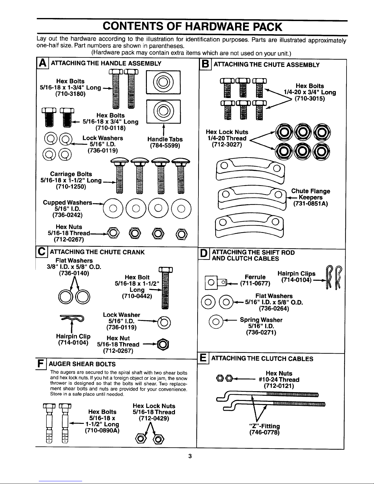
CONTENTS OF HARDWARE PACK
Lay out the hardware according to the illustration for identification purposes. Parts are illustrated approximately
one-half size. Part numbers are shown in parentheses.
(Hardware pack may contain extra items which are not used on your unit.)
A_ ATTACHING THE HANDLE ASSEMBLY
Hex Bolts [
5/16-18 x 1-3/4" Long
(710-3180)
[__ Hex Bolts
5116-18 x 3/4" Long
(710-0118)
(_(_ Lock Washers
5/16" I.D.
(_(_ (736-0119)
Carriage Bolts
5/16-18 x 1-1/2" Long
(710-1250)
@1
@
f
Handle Tabs
(784-5599)
Cupped Washers_
5/16" I.D. _ _
(736-0242) _._.j'
Hex Nuts
5/16-18 Thread-_,._ @
(712-0267)
C JATrACHING THE CHUTE CRANK
Flat Washers
318" I.D. x 518" O.D.
Hex Bolt
5/16-18 x 1-1/2"
Long
(710-0442)
Lock Washer
5116" I.D.
(736-0119)
Hairpin Clip Hex Nut
(714-0104) 5/16-18 Thread --_
(712-0267)
F.__ AUGER SHEAR BOLTS
The augers are secured to the spiral shaft with two shear bolts
and hex lock nuts. If you hit a foreign object or ice jam, the snow
thrower is designed so that the bolts will shear. Two replace-
ment shear bolts and nuts are provided for your convenience.
Store in a safe place until needed.
_ _.,_._ Hex Bolts
5/16-18 x
1-1/2" Long
(710-0890A)
Hex Lock Nuts
5/16-18 Thread
(712-0429)
S I ATTACHING THE CHUTE ASSEMBLY
TTT .exoo,,.
1/4-20 x 3/4" Long
TT T _ (710-3015)
Hex Lock Nuts.@@ @
1/4-20 Thread
@@@
ute Flange
Keepers
31-0851A)
D I ATTACHING THE SHIFT ROD
AND CLUTCH CABLES
Ferrule
(711-0677)
Hairpin Clips ['_
(714-0104) ---_
(_(_ Flat Washers
5/16" I.D. x 5/8" O.D.
(736-0264)
(_ Spring Washer
5/16" I.D.
(736-0271)
E__ ATTACHING THE CLUTCH CABLES
Hex Nuts
_ _ #10-24 Thread
(712-0121)
• V ""_'""""m"I_"""m'_l_
"Z'-Fitting
(746-0778)
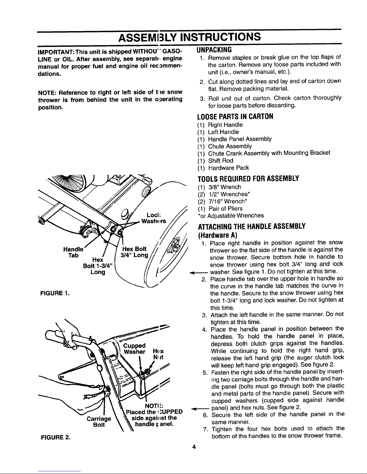
ASSEMI3LY INSTRUCTIONS
IMPORTANT: This unit is shipped WITHOU'" GASO-
LINE or OIL. After assembly, see separab_ engine
manual for proper fuel and engine oil rec:_mmen-
dations.
NOTE: Reference to right or left side of tile snow
thrower is from behind the unit in the operating
position.
Handle
Tab
Hex
Bolt 1-3/4"
Long
FIGURE 1.
Cupped
Washer Hq:x
N_it
FIGURE 2.
Carriage
Bolt
NOTI ":
Placed the q_UPPED
side agail _st the
handle _anel.
UNPACKING
1. Remove staples or break glue on the top flaps of
the carton. Remove any loose parts included with
unit (i.e., owner's manual, etc.).
2. Cut along dotted lines and lay end of carton down
flat. Remove packing material.
3. Roll unit out of carton. Check carton thoroughly
for loose parts before discarding.
LOOSE PARTS IN CARTON
(1) Right Handle
(1) Left Handle
(1) Handle Panel Assembly
(1) Chute Assembly
(1) Chute Crank Assembly with Mounting Bracket
(1) Shift Rod
(1) Hardware Pack
TOOLS REQUIRED FOR ASSEMBLY
(1) 3/8" Wrench
(2) 1/2" Wrenches*
(2) 7/16" Wrench*
(1) Pair of Pliers
*or Adjustable Wrenches
ATTACHINGTHE HANDLEASSEMBLY
(HardwareA)
1. Place right handle in position against the snow
thrower so the flat side of the handle is against the
snow thrower. Secure bottom hole in handle to
snow thrower using hex bolt 3/4" long and lock
washer. See figure 1. Do not tighten at this time.
Place handle tab over the upper hole in handle so
the curve in the handle tab matches the curve in
the handle. Secure to the snow thrower using hex
bolt 1-3/4" long and lock washer. Do not tighten at
this time.
3. Attach the left handle in the same manner. Do not
tighten at this time.
4. Place the handle panel in position between the
handles. To hold the handle panel in place,
depress both clutch grips against the handles.
While continuing to hold the right hand grip,
release the left hand grip (the auger clutch lock
will keep left hand grip engaged). See figure 2.
5. Fasten the right side of the handle panel by insert-
ing two carriage bolts through the handle and han-
dle panel (bolts must go through both the plastic
and metal parts of the handle panel). Secure with
cupped washers (cupped side against handle
panel) and hex nuts. See figure 2.
Secure the left side of the handle panel in the
same manner.
7. Tighten the four hex bolts used to attach the
bottom of the handles to the snow thrower frame.
4
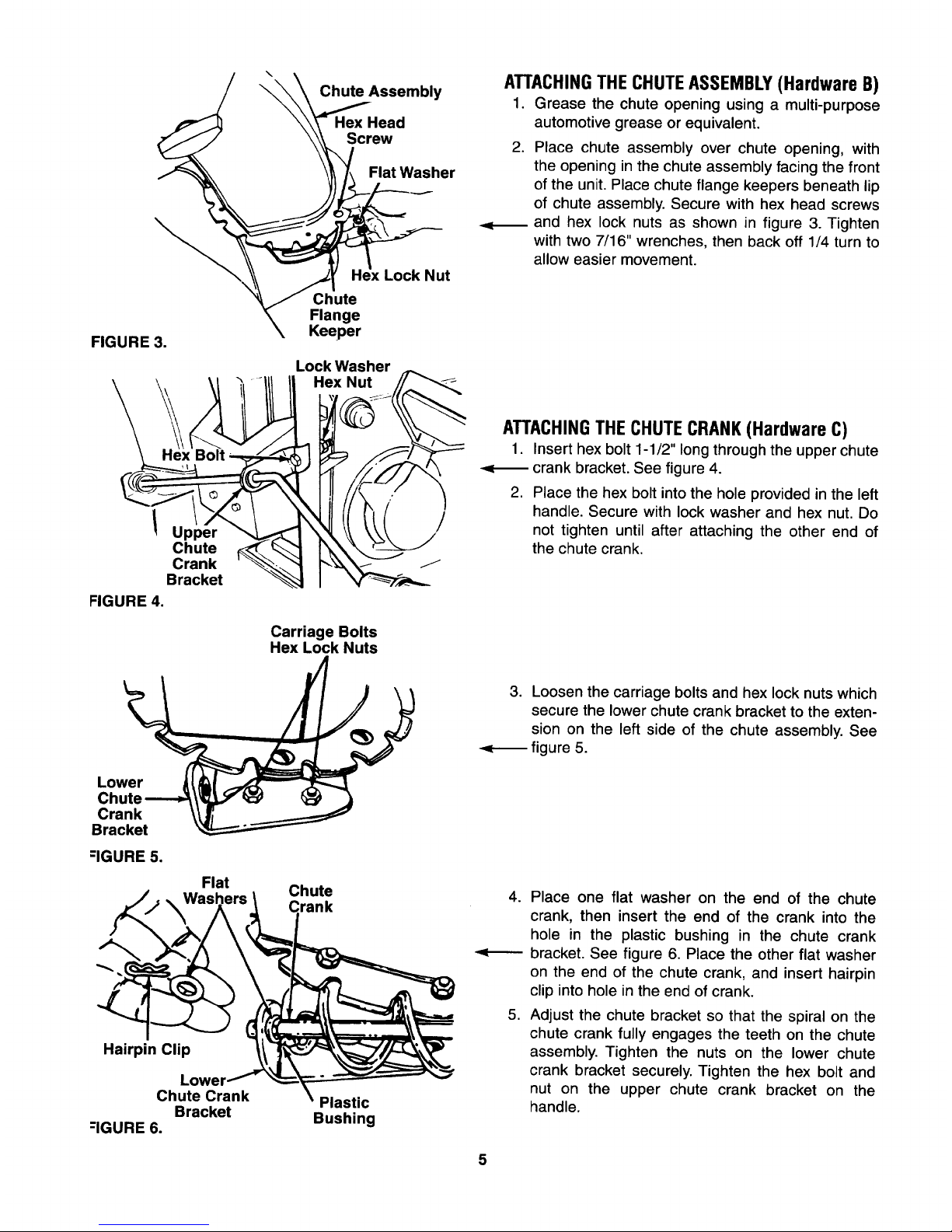
FIGURE 3.
\
Chute Assembly
Hex Head
Screw
Flat Washer
Lock Nut
Chute
Flange
Keeper
Lock Washer
Hex Nut
_m
ATTACHINGTHE CHUTEASSEMBLY(Hardware B)
1. Grease the chute opening using a multi-purpose
automotive grease or equivalent.
.
Place chute assembly over chute opening, with
the opening in the chute assembly facing the front
of the unit. Place chute flange keepers beneath lip
of chute assembly. Secure with hex head screws
and hex lock nuts as shown in figure 3. Tighten
with two 7/16" wrenches, then back off 1/4 turn to
allow easier movement.
Upper
Chute
Crank
Bracket
FIGURE 4.
Carriage Bolts
Hex Lock Nuts
ATTACHINGTHE CHUTECRANK (Hardware C)
1. Insert hex bolt 1-1/2" long through the upper chute
-<_ crank bracket. See figure 4.
2. Place the hex bolt into the hole provided in the left
handle. Secure with lock washer and hex nut. Do
not tighten until after attaching the other end of
the chute crank.
Lower
Chute
Crank
Bracket
-IGURE 5.
Flat
Hairpin Clip
Lower
Chute Crank
Bracket
--IGURE 6.
Chute
rank
Plastic
Bushing
3. Loosen the carriage bolts and hex lock nuts which
secure the lower chute crank bracket to the exten-
sion on the left side of the chute assembly. See
figure 5.
4. Place one flat washer on the end of the chute
crank, then insert the end of the crank into the
hole in the plastic bushing in the chute crank
bracket. See figure 6. Place the other flat washer
on the end of the chute crank, and insert hairpin
clip into hole in the end of crank.
5. Adjust the chute bracket so that the spiral on the
chute crank fully engages the teeth on the chute
assembly. Tighten the nuts on the lower chute
crank bracket securely. Tighten the hex bolt and
nut on the upper chute crank bracket on the
handle.
5

IMPORTANT:Attachthe shift rod andcl itch cables as follows. THEN CHECK THE ADJUSTMENTS AS
INSTRUCTED, AND MAKE ANY FINAL A[)JUSTMENTS NECESSARY BEFORE OPERATING YOUR SNOW
THROWER. Failure to follow the instructi,)ns may cause damage to the snow thrower.
Tracti°_ hiftClutchDrive Lever
I1 Washer Fer u e
J/Shift
1Arm
_ssembly
ATTACHINGTHE SHIFT ROD (Hardware D)
1. Place the shift lever (on the handle panel) in the
sixth (6) speed position (all the way forward).
Place the bent end of the shift rod into the hole in
the shift arm assembly. See figure 7. Secure with
spring washer, flat washer and hairpin clip.
3. Start threading the ferrule onto the other end of the
shift rod. Push down on the shift rod (and shift arm
assembly) as far as it will go.
4. Thread the ferrule onto the shift rod until the ferrule
lines up with the upper hole in the shift lever
(beneath the handle panel). Insert the ferrule into
the upper hole in the shift lever from the left side
when adjustment is correct. Secure with flat
washer and hairpin clip.
Make certain to check for correct adjustment of the
shift rod as instructed in the Final Adjustment section
before operating the snow thrower.
FIGURE 7.
Hex Jam
Nut
/
/
Cable is Strai
FIGURE 8.reViewed from Underside of H_nndle
Panel
ATTACHINGTHE CLUTCH CABLES(Hardware E)
The "Z" end of the clutch cables are hooked into the
clutch grips on each handle. Attach cables as follows.
1. Thread the hex nuts (in hardware pack) all the
way up the threaded portion of the "Z" ends of the
clutch cables.
2. Make certain each cable is in groove of cable
roller guides. Place the clutch grip in the raised
(up) position.
3. Thread the cable onto the threaded portion of the
"Z" end until there is no slack in the cable, but the
cable is NOT tight. Do not overtighten cable.
See figure 8.
&
WARNING: If cable is tightened so there is
tension on the cable with the clutch grip
released, the safety features of the snow
thrower may be overridden.
4. When correct adjustment is reached, tighten the
hex nut against the bottom portion of the cable to
lock it in position.
FINAL ADJUSTMENTS
Auger Drive Clutch
To check the adjustment of the auger drive clutch,
push forward on the left hand clutch grip (depress the
rubber bumper). There should be slack in the cable.
Release the clutch grip. The cable should be straight.
Make certain you can depress the auger drive clutch
grip against the left handle completely.
 Loading...