

Page 1
OPERATOR’S MANUAL
FRONT TINE
TILLERS
300 Series
IMPORTANT: READ
SAFETY RULES AND
INSTRUCTIONS CAREFULLY
MTD PRODUCTS LTD. P.O. BOX 1386 KITCHENER, ON N2G 4J1
PRINTED IN THE U.S.A.
772C0730
(10/04)
Page 2

TABLE OF CONTENTS
Content Page
Customer Support 2
Important Safe Operation Practices 3
Assembly 5
Controls 7
Operation 8
Adjustments 10
Content Page
Lubrication 11
Maintenance 11
Off-Season Storage 13
Troubleshooting 13
Parts Lists/Pièces détachées 14
Warranty 18
FINDING MODEL NUMBER
This Operator’s Manual is an important part of your new equipment. It will help you assemble, prepare and maintain the unit for best
performance. Please read and understand what it says.
Before you start assembling your new equipment, please locate the model plate on the equipment and copy the information from
it in the space provided below. A sample model plate is also given below. You can locate the model plate by standing at the operating
position and looking down at the rear of the deck . This information will be necessary to use the manufacturer’s web site and/or help
from the Customer Support Department or an authorized service dealer.
This is where your model number will be.
Model Number
Numéro de modèle
XXXXXXXXXX
www.mtdcanada.com
Serial Number
Numéro de série
XXXXXXXXXXX
MTD PRODUCTS LIMITED
KITCHENER, ON N2G 4J1
1-800-668-1238
This is where your serial number will be.
Copy the model number here:
Copy the serial number here:
ENGINE INFORMATION
The engine manufacturer is responsible for all engine-related issues with regards to performance, power-rating, specifications, warranty and
service. Please refer to the engine manufacturer’s Owner’s/Operator’s Manual packed separately with your unit for more information.
CALLING CUSTOMER SUPPORT
Please do NOT return the unit to the retailer from which it was purchased, without first contacting Customer Support.
If you have difficulty assembling this product or have any questions regarding the controls, operation or maintenance of this unit,
please call a Customer Support Representataive.
For US Customers: 1- (330) 220-4MTD (4683) or 1- (800)-800-7310
For Canadian Customers: 1-800-668-1238
Please have your unit’s model number and serial number ready when you call. See previous section to locate this information. You will be asked
to enter the serial number in order to process your call.
HOW TO OBTAIN SERVICE
Service is available, WITH PROOF OF PURCHASE, through your local authorized service dealer. To locate the dealer in your
area;
In the U.S.A.
Ohio 44136-0019, or call 1-800-800-7310 or 1-330-220-4683 or log on to our Web site at www.mtdproducts.com.
In Canada
www.mtdcanada.com.
: Check your Yellow Pages, or contact customer support listed about MTD LLC at P.O. Box 361131, Cleveland,
: Contact MTD Products Limited, Kitchener, ON N2G 4J1, or call 1-800-668-1238 or log on to our Web site at
2
Page 3

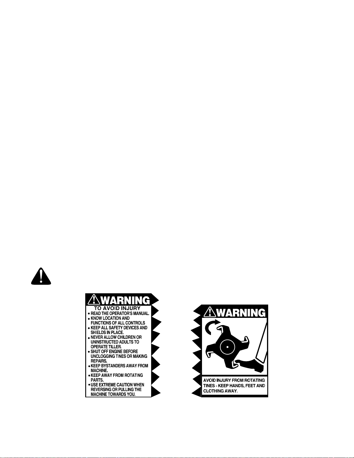
SECTION 1: IMPORTANT SAFE OPERATION PRACTICES
WARNING: This symbol points out important safety instructions which, if not followed, could endanger
the personal safety and/or property of yourself and others. Read and follow all instructions in this manual
before attempting to operate your tiller. Failure to comply with these instructions may result in personal
injury. when you see this symbol— HEED ITS WARNING
DANGER: Your tiller was built to be operated according to the rules for safe operation in this manual.
As with any type of power equipment, carelessness or error on the part of the operator can result in
serious injury. This tiller is capable of amputating hands and feet. Failure to observe the following safety
instructions could result in serious injury or death.
TRAINING
1. Read, understand, and follow all instructions on the
machine and in the manual(s) before attempting to
assemble and operate. Keep this manual in a safe
place for future and regular reference and for
ordering replacement parts.
2. Be familiar with all controls and their proper
operation. Know how to stop the machine and
disengage them quickly.
3. Never allow children under 14 years old to operate
this machine. Children 14 years old and over should
read and understand the operation instructions and
safety rules in this manual and should be trained
and supervised by a parent.
4. Never allow adults to operate this machine without
proper instruction.
5. Keep bystanders, helpers, children and pets at
least 75 feet from the machine while it is in
operation. Stop machine if anyone enters the area.
PREPARATION
1. Thoroughly inspect the area where the equipment is to be used. Remove all stones, sticks, wire, and other foreign objects which could be tripped over and cause personal injury.
2. Wear sturdy, rough-soled work shoes and closefitting slacks and shirts. Loose fitting clothes and
jewelry can be caught in movable parts. Never
operate this machine in bare feet or sandals.
3. Disengage clutch levers and shift (if provided) lever into neutral ("N") before starting the engine.
4. Never leave this machine unattended with the engine running.
5. Never attempt to make any adjustments while the engine is running, except where specifically recommended in the operator’s manual.
6. To avoid personal injury or property damage use
extreme care in handling gasoline. Gasoline is
extremely flammable and the vapors are
explosive. Serious personal injury can occur when
gasoline is spilled on yourself or your clothes
which can ignite. Wash your skin and change
clothes immediately.
7. Use only an approved gasoline container.
8. Extinguish all cigarettes, cigars, pipes and other
9. Never fuel machine indoors.
10. Never remove gas cap or add fuel while the
11. Allow engine to cool at least two minutes before
12. Never over fill fuel tank. Fill tank to no more than
13. Replace gasoline cap and tighten securely.
14. If gasoline is spilled, wipe it off the engine and
15. Never store the machine or fuel container inside
16. Allow a machine to cool at least 5 minutes before
OPERATION
1. Do not put hands or feet near rotating parts.
2. Do not operate the machine while under the
3. Never operate this machine without good visibility
4. Keep bystanders, helpers, children and pets at
5. Be careful when tilling in hard ground. The tines
6. Exercise extreme caution when operating on or
7. Never operate the machine at high transport
8. Exercise caution to avoid slipping or falling.
.
sources of ignition.
engine is hot or running.
refueling.
½ inch below bottom of filler neck to allow space
for fuel expansion.
equipment. Move unit to another area. Wait 5
minutes before starting the engine.
where there is an open flame, spark or pilot light
as on a water heater, space heater, furnace,
clothes dryer or other gas appliances.
storing.
Contact with the rotating parts can amputate
hands and feet.
influence of alcohol or drugs.
or light. Always be sure of your footing and keep a
firm hold on the handles.
least 75 feet from the machine while it is in
operation. Stop machine if anyone enters the area.
may catch in the ground and propel the tiller
forward. If this occurs, let go of the handle bars and
do not restrain the machine.
crossing gravel surfaces. Stay alert for hidden
hazards or traffic. Do not carry passengers.
speeds on hard or slippery surfaces.
3
Page 4
9. Look down and behind and use care when in reverse or pulling machine towards you.
10. Start the engine according to the instructions found in this manual and keep feet well away from the tines at all times.
11. After striking a foreign object, stop the engine, disconnect the spark plug wire(s) and ground against the engine. Thoroughly inspect the machine for any damage. Repair the damage before starting and operating.
12. Disengage all clutch levers and stop the engine before you leave the operating position (behind the handles). Wait until the tines come to a complete stop before unclogging the tines, making any adjustments, or inspections.
13. Never run an engine indoors or in a poorly ventilated area. Engine exhaust contains carbon monoxide, an odorless, and deadly gas.
14. Muffler and engine become hot and can cause a burn. Do not touch.
15. Use caution when tilling near fences, buildings and underground utilities. Rotating tines can cause property damage or personal injury.
16. Do not overload machine capacity by attempting to till soil too deep at too fast of a rate.
17. If the machine should start making unusual noise or vibration, stop the engine, disconnect the spark plug wire and ground it against the engine. Inspect thoroughly for damage. Repair any damage before starting and operating.
18. Keep all shields, guards and safety devices in place and operating properly.
19. Never pick up or carry machine while the engine is running.
20. Use only accessories and attachments approved for this machine by the machine manufacturer. Failure to do so, can result in serious injury.
21. If situations occur which are not covered in this manual, use care and good judgment. Contact your authorized dealer for assistance.
MAINTENANCE & STORAGE
1. Never tamper with safety devices. Check their proper operation regularly.
2. Check bolts and screws for proper tightness at frequent intervals to keep the machine in safe working condition. Also, visually inspect machine for any damage.
3. Before cleaning, repairing, or inspecting, make certain the tine(s) and all moving parts have stopped. Disconnect the spark plug wire and ground against the engine to prevent unintended starting.
4. Do not change the engine governor settings or over-speed the engine. The governor controls the maximum safe operating speed of the engine.
5. Maintain or replace safety and instruction labels, as necessary.
6. Follow this manual for safe loading, unloading, transporting, and storage of this machine.
7. Never store the machine or fuel container inside where there is an open flame, spark or pilot light as on a water heater, space heater, furnace, clothes dryer or other gas appliances.
8. Always refer to the operator’s manual for proper instructions on off-season storage.
9. If the fuel tank has to be drained, do this outdoors.
10. Observe proper disposal laws and regulations for gas, oil, etc. to protect the environment.
WARNING — YOUR RESPONSIBILITY: Restrict the use of this power machine to persons who read,
understand and follow the warnings and instructions in this manual and on the machine.
Figure 1 Safety labels found on your unit
4
Page 5
SECTION 2: ASSEMBLY INSTRUCTIONS
IMPORTANT: This unit is shipped WITHOUT
GASOLINE or OIL. After assembly, see separate
engine manual for proper fuel and engine oil
recommendations.
NOTE: Left and right is determined from the
operator’s position, standing behind the tiller.
REMOVING UNIT FROM CARTON
• Remove staples, break glue on top flaps, or cut
tape at carton end and peel along top flap to open
carton.
• Remove all loose parts included with unit (i.e.,
operator’s manual, etc.)
• Cut along corners, lay carton down flat, and remove
packing material.
• Roll or slide unit out of carton and check carton
thoroughly for loose parts.
• Extend control cable(s) to the rear of the tiller and
lay them on the floor. Be careful not to bend or kink
control cable(s).
TOOLS REQUIRED FOR ASSEMBLY
(1)-1/2" Wrench or Socket*
(1)-Pair of Pliers
(1)-3/8" Wrench*
*An adjustable wrench may be used.
This owner's guide covers two different model
tillers. Model 340 has forward tine drive only.
Model 390 has both forward and reverse tine drive.
Follow only the instructions which pertain to your
model tiller. See the model plate on your tiller for
the correct model number.
LOOSE PARTS IN CARTON
1. Tailpiece
2. Depth Stake
3. Handle Assembly
NOTE: All hardware required for assembly has been
placed in position on the tiller.
Hex Nut and
Cupped Washer
Tailpiece
Depth
Stake
Self-Tapping
Screws
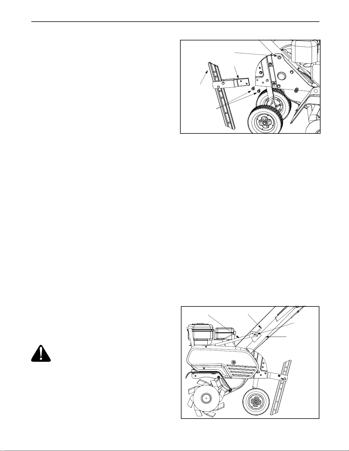
Figure 2
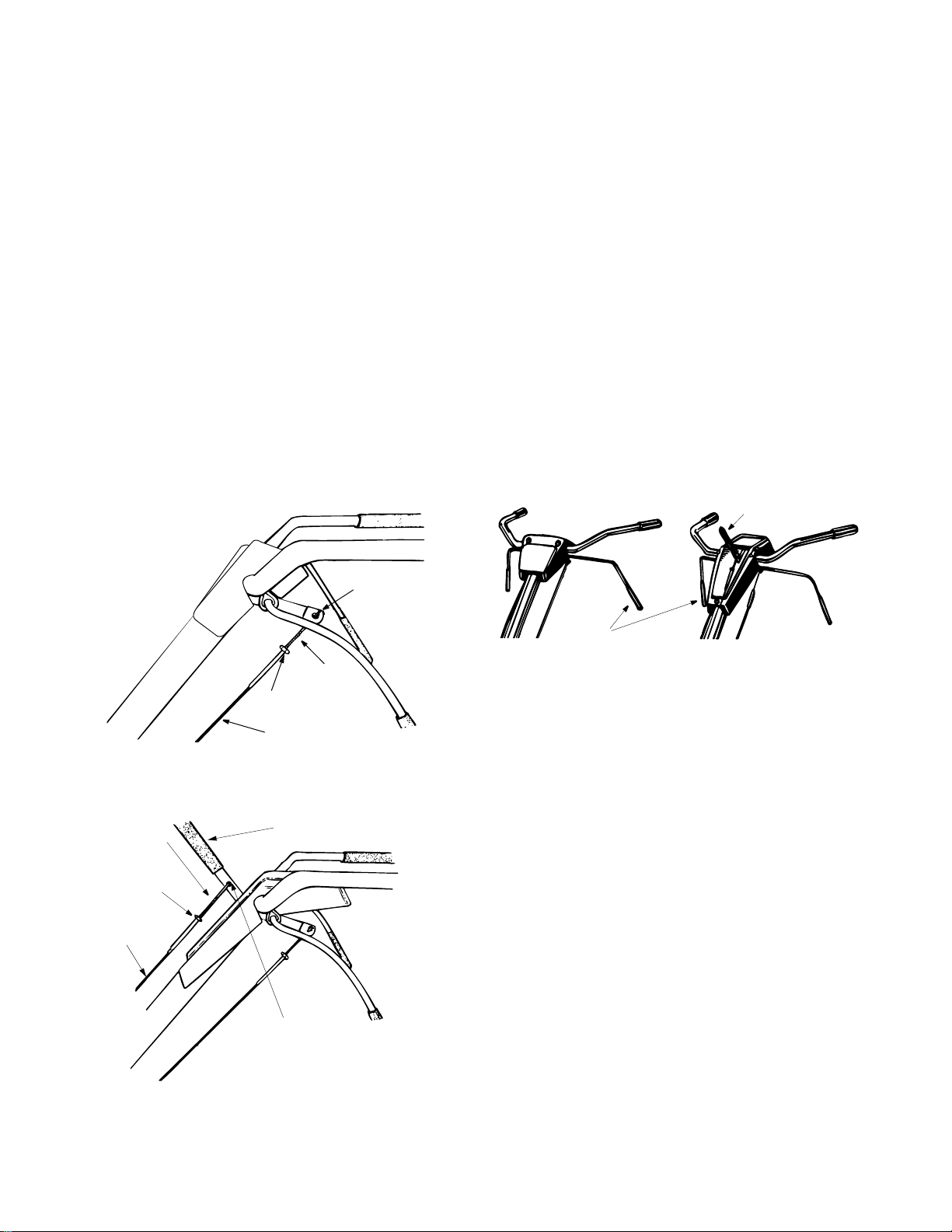
ATTACHING THE HANDLE ASSEMBLY
1. Remove the hex bolt and cupped washer from the top right side of the frame halves. Hold the cable guide bracket on the left side of the frame as it will fall when the bolt is removed. See Figure 3.
2. Insert the handle assembly between the two frame
halves. Insert the hex bolt just removed through
the frame halves, handle assembly, and into the
cable guide bracket (notch in cable guide bracket
goes over the flange on the frame). Tighten
securely.
3. Loosen the hand knob which secures the handle brace to the handle assembly.
4. Remove the handle knob and hardware from the handle brace. Insert the carriage screw through the welded bracket on the handle and into the end of the handle brace. See Figure 3.
5. Secure with cupped washer and handle knob.
6. Select one of the three handle height positions (three notches in welded bracket), and tighten the hand knob to secure the handle in desired position. Make certain carriage bolt is seated securely into one of the three positions provided.
Handle
Brace
Handle
Crank
U-Nut
BEFORE ASSEMBLY
WARNING: Disconnect the spark plug wire
and ground against the engine to prevent
unintended starting.
ATTACHING THE TAILPIECE AND DEPTH STAKE
1. Remove the two self-tapping screws on the frame. Slide the tailpiece into the frame, with the lower hole in the tailpiece toward the front.
2. Secure with screws just removed. See Figure 2.
Handle
Assembly
Figure 3
5
Page 6
ATTACHING THE CLUTCH CONTROL CABLES
FORWARD CABLE
Attach the end of the forward cable to the bracket
underneath the handle assembly as follows. (On
model 390, the forward clutch cable is the cable which
is attached closer to the rear of the tiller).
1. Loosen the hex nut on the threaded rod near the end of the cable, and move it up the rod as far as it will go. See
2. Unthread the rod from the rest of the cable. Hook the “Z” end of the rod into the bracket underneath the handle assembly from the right hand side. See Figure 4 or Figure 5.
3. Thread the rod back into the cable until the cable is straight. Do not tighten it enough to put any tension on the spring. See Figure 4 or Figure 5.
4. Thread the hex nut down against the end of cable. Use a pair of pliers and a wrench to lock the nut against the rod.
NOTE: Do not overtighten control cable. Too much
tension may cause it to break when engaged.
REVERSE CABLE (Model 390 Only)
The reverse clutch cable is the cable which is attached
closer to the front of the tiller. Attach the end of the
reverse cable to the reverse tine engagement handle
above the handle assembly, in the same manner as
you attached the forward cable. See Figure 5.
FINAL CLUTCH ADJUSTMENT
To check the clutch cable adjustment, proceed as
follows.
1. Disconnect the spark plug wire and move it away from the spark plug to prevent accidental starting.
2. Engage and release the forward tine engagement
handle, then the reverse tine engagement lever
(model 390 only). If an excessive noise is heard
when releasing either the tine drive clutch handle
or lever, the cable may be too loose. Adjust either
the forward or reverse clutch cable by loosening
the hex nut, threading the rod into the cable one or
two turns, then retightening the nut. See Figure 6.
Model 340
Reverse Tine
Engagement Handle
Threaded
Rod
Hex Nut
Reverse
Cable
Threaded
Rod
Hex Nut
Cable
Figure 4 Model 340
Reverse Tine
Engagement Handle
“Z” End
Hooked In
Bracket
Engagement Handle
3. With tine engagement handles in neutral
(released) as shown in Figure 6, pull the starter
rope several times. The tines should not turn. If
they turn forward, loosen the hex nut on the
forward cable (underneath the handle assembly).
See Figure 5. If they turn toward the rear (model
390 only), loosen the hex nut on the reverse cable
(above the handle assembly). Unthread the rod
from the cable 2 or 3 turns. Retighten the hex nut,
and check again for correct adjustment. See
Figure 6.
Tine
Model 390
Figure 6
“Z” End
Hooked In
Bracket
Figure 5 Model 390
6
Page 7
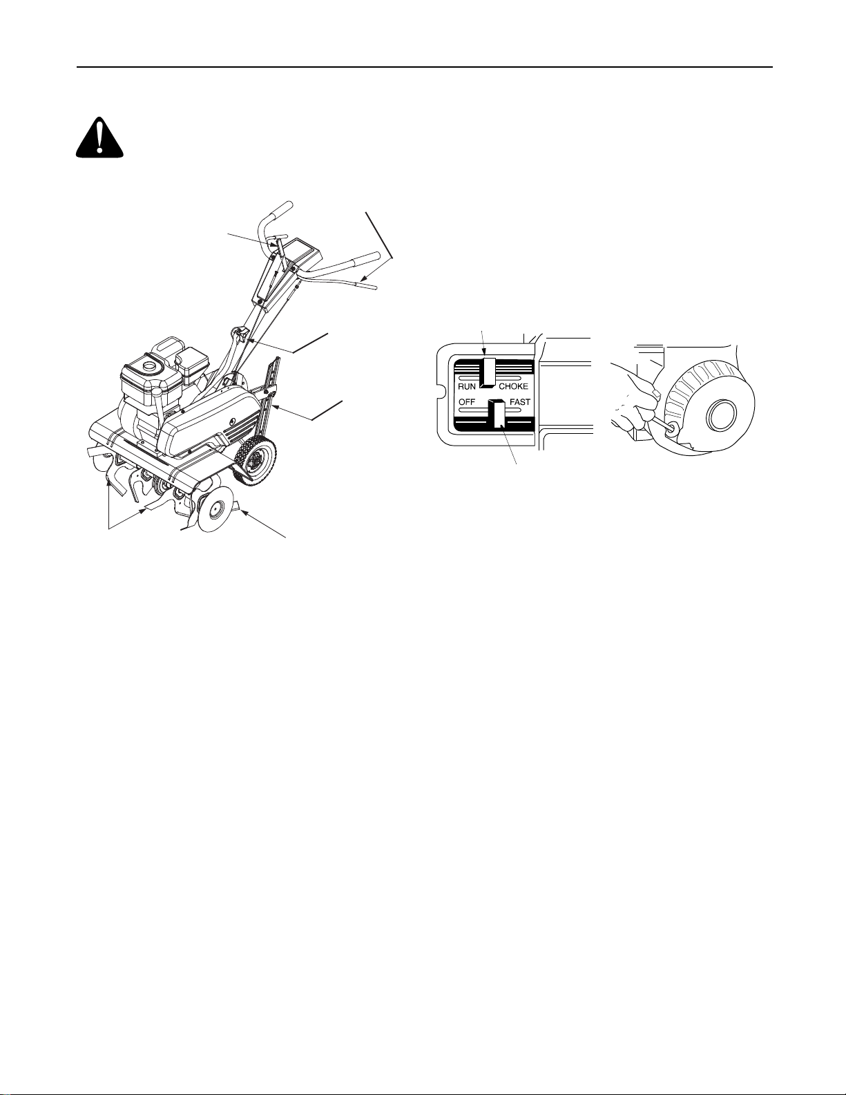
SECTION 3: CONTROLS
Tines
WARNING: Read, understand, and follow
all instructions and warnings on the machine
and in this manual before operating.
Forward Tine
Engagement
Reverse Tine
Engagement
Lever
Figure 7 Model 390 Shown
Lever
End
Cap
Handle Knob
Depth Stake
REVERSE TINE DRIVE CLUTCH LEVER
(Model 390 Only)
The reverse tine drive clutch lever is located on top of
the handle panel. Pull the lever to the rear to move the
tines in reverse. Release the lever to stop the reverse
tine drive. See Figure 7.
NOTE: Never engage both the forward and reverse
tine drives at the same time. Engaging both forward
and reverse tine drives at the same time could damage
the belt drives and cause the engine to stall.
Choke
Models 340/390
Throttle Control
Figure 8
DEPTH STAKE
The depth stake controls the tilling depth. Refer to
"HOW TO USE YOUR TILLER" SECTION" for more
details.
THROTTLE CONTROL
The throttle control lever is located on the engine. It controls the engine speed and stops the engine. See Figure 8.
CHOKE LEVER
The choke lever is located above the throttle control. It
is used to enrich the fuel mixture when starting a cold
engine. See Figure 8.
FORWARD TINE ENGAGEMENT HANDLE
The forward tine engagement handle is located
beneath the tiller handle. Squeezing the handle up
against the tiller handle engages the tines. Release the
handle to stop the tines. See Figure 7.
TINE AND END CAPS
The tilling tines and end caps are used to cultivate,
furrow, and prepare your garden for seeding. The end
caps are used to avoid tilled soil from overflowing onto
unwanted areas.
HANDLE KNOB
The handle knob is attached to the handle and is used
to adjust the height of the handle to three different
settings.
ENGINE CONTROLS
See the separate engine manual for the location and
function of the other controls on the engine.
7
Page 8
SECTION 4: OPERATION
WARNING: Read, understand, and follow
all instructions and warnings on the machine
and in this manual before operating.
GAS AND OIL FILL-UP
Service the engine with GASOLINE and OIL as
instructed in the separate engine manual packed with
your tiller. Read instructions carefully.
WARNING: Use extreme care when
handling gasoline. Gasoline is extremely
flammable and the vapors are explosive.
Never fuel machine indoors or while the
engine is hot or running.
TO START ENGINE
WARNING:
front of the tiller while the engine is running or
being started.
1. Attach spark plug wire to spark plug. Make certain the metal loop on the end of the spark plug wire (inside the boot) is fastened securely over the metal tip on the spark plug.
2. Make certain the tine engagement controls are in the neutral position (released). See Figure 7.
3. Place the throttle control lever in FAST position. (See Figure 8 ).
4. Move choke lever to CHOKE position. (A warm engine requires little or no choke.)
5. Grasp starter handle and pull rope out slowly until engine reaches start of compression cycle (rope will pull slightly harder at this point). Let the rope rewind slowly.
6. Pull rope with a rapid, continuous, full arm stroke. Keep a firm grip on starter handle. Let rope rewind slowly. Do not let starter handle snap back against starter. Repeat preceding instructions 5 and 6 until engine starts.
7. When engine starts, move choke lever on engine halfway between CHOKE and RUN.
8. Move throttle control to IDLE position for a few minutes warm-up. Move choke lever to RUN position as engine warms up.
Be sure no one is standing in
WHEEL POSITION
NOTE:
such that the unit sits level. While tilling, as the tines
enter the ground and the front of the tiller lowers, the
wheels must be raised to level the unit. Follow the
steps below to adjust the wheels.
• Remove the clevis pin and hairpin clip from wheel
The tiller is shipped with the wheels adjusted
yoke, raising the wheels to the desired height, and
replacing the clevis pin and hairpin clip. (See Figure
9.)
Depth
Stake
Wheel Yoke
Hairpin Clips
and Clevis Pins
Figure 9
REMOVING END CAPS
The end cap are used to avoid tilled soil from getting
onto unwanted areas. You can remove each end cap
from the outer axle by removing the hairpin clip and
clevis pin that secure it. Slide end cap off the axle to
remove. See Figure 10.
NOTE: After starting engine and prior to using the
tiller, be certain to check the clutch adjustment as
described in “Finall Clutch Adjustment” section of the
Assembly Instructions.
TO STOP ENGINE
1. Move throttle control lever to STOP or OFF position.
2. Disconnect spark plug wire from spark plug and ground against the engine to prevent accidental starting while equipment is unattended.
8
Clevis
Pin
End
Cap
Hairpin Clip
Figure 10
Page 9
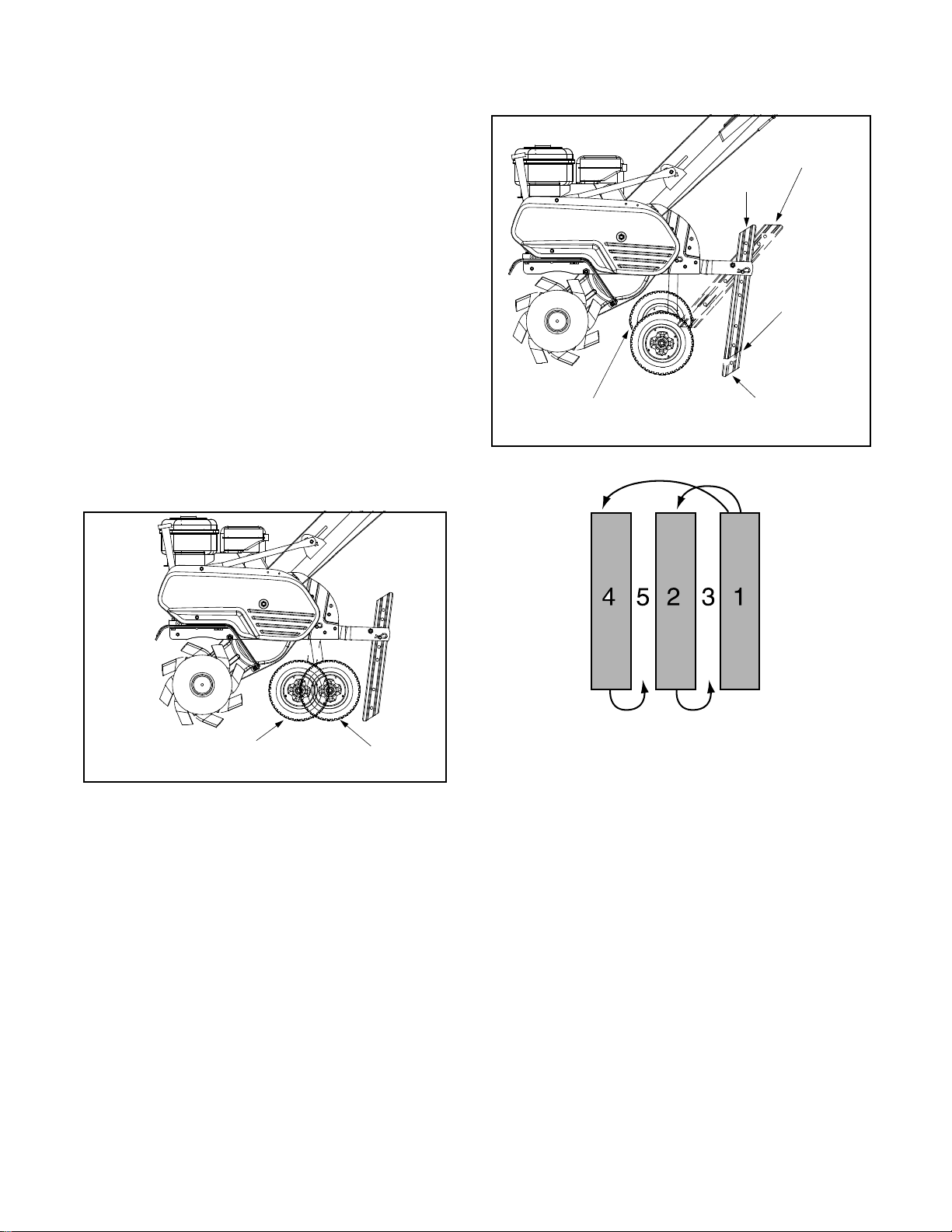
CONTROLLING SPEED AND TILLING DEPTH
WHEEL YOKE ADJUSTMENT:
1. Place wheel yoke so that the wheels are forward (nearest point between wheels and tines) for shallow tilling, cultivating and transport. The forward speed will increase.
2. Turn yoke around (farthest point between wheels and tines) for deep tilling. Forward speed will decrease. (See Figure 11.)
the garden. Passes should be made across the length
and width of the garden alternately. Rocks which are
turned up should be removed from the garden area.
Transport
Depth
Stake
Position
Depth Stake Adjustment:
The depth stake acts as a brake for the tiller and
controls the depth and speed at which the machine will
operate.
1. By increasing the depth of the depth stake, the forward speed of the machine is reduced, and the working depth is increased. (See Figure 12.)
2. When the depth stake is raised, the working depth of the machine is reduced and the forward speed is increased.
• Remove the clevis pin and hairpin clip to raise or
lower depth stake. (See Figure 9.)
Raised Wheel Setting
For Deep Tilling
Figure 12
Shallow Tilling
Fast Forward
Deep Tilling
Slow Forward
Shallow
Tilling
Figure 11
Deep
Tilling
IMPORTANT: The working depth of the machine
may be predetermined by setting the depth stake and
wheels so that the wheels are about four inches from
the ground when the tines and depth stake are resting
on the ground. This setting will permit a working depth
of about four inches. When presetting the working
depth, the handles should be adjusted so the hand
grips are a little above waist height because the tiller
will be lower when the tines and depth stake penetrate
the ground. See Figure 12.
When tilling, leave approximately 8 inches of untilled
soil between the first and second tilling paths, then
make the third path between the first and second as
shown in Figure 13. In some soils, the desired depth is
obtained the first time over the garden. In other soils,
the desired depth is obtained by going over the garden
two or three times. In the latter case, the depth stake
should be lowered before each succeeding pass over
Figure 13
Handle Pressure:
Further control of tilling depth and travel speed can be
obtained by variation of pressure on the handles.
1. A downward pressure on the handles will reduce the working depth and increase the forward speed.
2. An upward pressure on the handles will increase the working depth and reduce the forward speed.
NOTE: The type of soil and working conditions will
determine the actual setting of the depth stake and the
handle pressure required.
Throttle Control: The throttle control lever adjusts the
engine speed and stops the engine. With the throttle
control lever pushed completely forward, the carburetor
is in START position. Pulling the throttle control back
slightly adjusts the engine speed to FAST. Pulling the
throttle back further reduces the engine speed to
SLOW. Pull the throttle completely back to stop the
engine.
Use maximum engine speed for deep tilling. Move the
throttle control to SLOW when transporting the tiller.
9
Page 10
TRANSPORTING THE TILLER
To transport the tiller to or from the garden, pivot the
depth stake forward, out of the way. (See Figure 12.)
With the throttle control in SLOW position, the unit will
walk freely on top of the lawn. If the operator does not
allow the tiller to move freely, the unit will start to till
the surface.
HOW TO USE YOUR TILLER
Your tiller is a precision built machine designed for
seed bed preparation, cultivating, furrowing and
mulching. It is engineered to minimize the hardest
work in the vegetable or flower garden, to till the soil
for planting and cultivating, and to perform many other
useful labor saving tasks in the garden. With the
proper amount of care and maintenance, this machine
will provide the owner with many years of service.
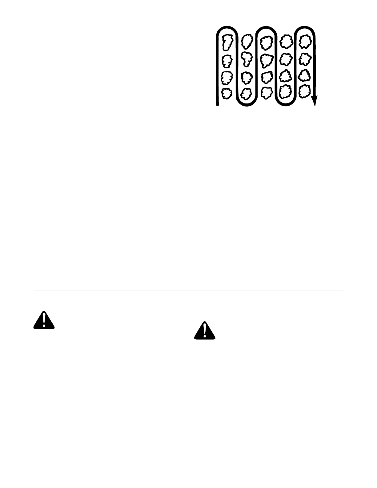
CULTIVATING
For cultivating, a two to three inch depth is desirable.
Set the wheels and depth stake so that the wheels are
about two inches above the ground while the tiller is
resting on the tines and depth stake will allow the
machine to work at cultivating depth. The throttle
should be set to control forward movement to a slow
walking speed. With the outer tines installed, the
working width of the machine is 22 or 24 inches. For
cultivation, this may be reduced to 13 inches by
removing the outer tines. Refer to Tine Width
Adjustment in Adjustment section. When laying out
plant rows, be sure to allow enough width to permit
cultivation between the rows. In growing corn or similar
crops, check-row planting will permit cross cultivation
and practically eliminate hand hoeing. (See .Figure
14).
Figure 14
The tiller has many uses other than tilling and
cultivating a garden. One of these is the preparation of
lawn area for seeding. The tiller will prepare a deep
seed bed which will be free of hard untilled spots,
allowing a better stand of grass to grow. The tiller is
very useful for loosening hard soil for excavation with a
shovel. No tedious hand pickwork will be necessary.
Your tiller may be used for mixing compost in the pile,
or for mixing it with the soil in your garden. This should
be done after the soil has been broken to the full
working depth. The compost should be worked in to a
depth of six to seven inches. This may be done by
working the length of the garden, and then by making
separate passes across its width. The addition of
decayed organic matter will substantially increase the
fertility of your garden. For proper decaying action,
fertilizer should be applied and worked in with the
mulch materials. Breaking up leaves and straw and
mixing it with several inches of soil causes the soil to
hold moisture longer and allows proper aeration of the
plant root system. This also retards the growth of
weeds.
SECTION 5: ADJUSTMENTS
WARNING: Disconnect the spark plug
wire and ground against the engine before
performing any adjustments, repairs, or
maintenance.
WHEEL ADJUSTMENTS
To adjust the wheel yoke and wheel position, refer to
WHEEL POSITION on page 8.
DEPTH STAKE ADJUSTMENT
To adjust the depth stake, refer to WHEEL POSITION
on page 8.
CLUTCH CONTROL ADJUSTMENTS
Periodic adjustment of the belt tension may be required
due to normal stretch and wear on the belt. To adjust
the clutch control lever, refer to the Final Adjustment
section of assembly instructions.
ENGINE
Refer to the separate engine manual for engine adjustment instructions.
CARBURETOR ADJUSTMENT
WARNING: If any adjustments are made
to the engine while the engine is running
(e.g. carburetor), disengage all clutches and
tines. Keep clear of all moving parts. Be
careful of heated surfaces and muffler.
Minor carburetor adjustment may be required to
compensate for differences in fuel, temperature,
altitude or load. If adjustments are needed, refer to the
engine manual packed with the tiller.
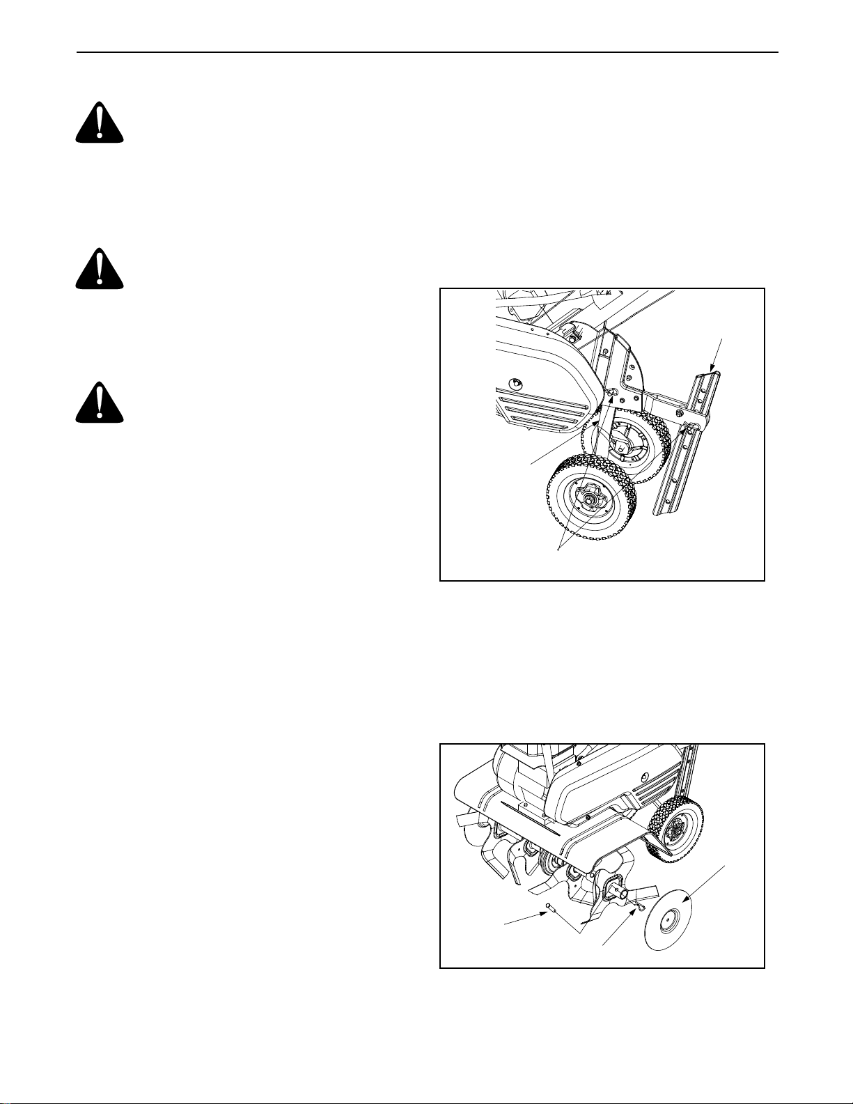
TINE WIDTH ADJUSTMENT
The tilling width of the unit is 22 inches. (See Figure
15.) Tilling width can be increased to 24 inches by
removing the clevis pins and hairpin clips, sliding the
outer tines out one inch, and securing in this position
with the clevis pins and hairpin clips. (See Figure 16.)
For cultivation, reduce the tine width to 13 inches by
removing the outer tines completely. (See Figure 17.)
10
Page 11
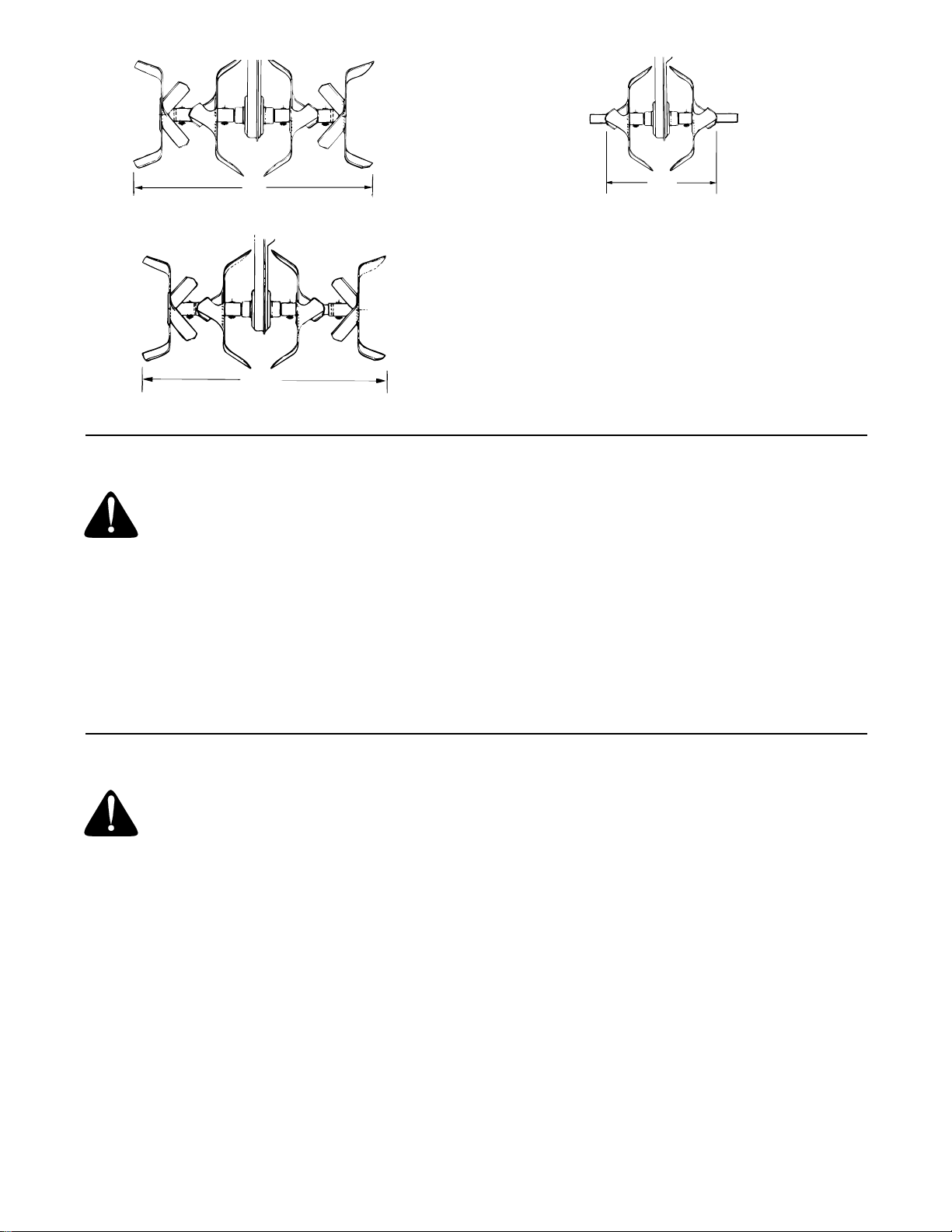
22"
Figure 15
24"
Figure 16
SECTION 6: LUBRICATION
13"
Figure 17
NOTE: A dirty air cleaner will cause engine to run
rough. Be certain air cleaner is clean and attached to
the carburetor before adjusting carburetor. Do not
make unnecessary adjustments. Factory settings are
satisfactory for most applications and conditions.
WARNING: Always stop engine and
disconnect spark plug wire before cleaning,
lubricating or doing any kind of work on tiller.
Tine Engagement Handle/Lever
• Lubricate the pivot points on the tine handle/lever
and the cable at least once a season with light oil.
The controls must operate freely in both directions.
Pivot Points
• Lubricate all pivot points and linkages at least once
a season with light oil.
SECTION 7: MAINTENANCE
WARNING: Disconnect spark plug wire
and ground it against the engine before
performing any repairs or maintenance.
TROUBLE SHOOTING
Refer to page 13 of this manual for trouble shooting
information.
ENGINE
Refer to the separate engine manual for all engine
maintenance instructions.
Maintain engine oil as instructed in the separate
engine manual packed with your unit. Read and follow
instructions carefully.
IMPORTANT: Do not attempt to start the engine
when the oil level is inadequate.
Service air cleaner every 25 hours under normal
conditions. Clean after every hour under extremely
dusty conditions. Poor engine performance and
flooding usually indicates that the air cleaner should be
Tine Shafts
• Remove the tine assemblies and lubricate the tine
shafts at least once a season.
Wheel Shafts
• Remove wheel assemblies and lubricate the axle
shafts at least once a season.
Transmission
• The transmission is pre-lubricated and sealed at
the factory. It requires no checking unless the
transmission is disassembled. See an authorized
service dealer if the transmission is disassembled.
serviced. To service the air cleaner, refer to the
separate engine manual packed with your unit.
IMPORTANT: Never run your engine without air
cleaner completely assembled.
The spark plug should be cleaned and the gap reset
after every 25 hours of engine operation. Spark plug
replacement is recommended at the start of each
season; check engine manual for correct plug type and
gap specifications.
Clean the engine regularly with a cloth or brush.
Keep the cooling system (blower housing area) clean
to permit proper air circulation which is essential to
engine performance and life. Be certain to remove all
dirt and combustible debris from muffler area.
CLEANING THE TINE AREA
Clean the underside of the tine shield after each use.
The dirt washes off the tines easier if washed off
immediately instead of after it dries.
11
Page 12

NOTE: We do NOT recommend the use of pressure
washers to clean your unit. They may cause damage
to electric components, spindles, pulleys, bearings or
the engine. The use of pressure washers will result in
shortened life and reduced serviceability.
BELT REMOVAL AND REPLACEMENT
Your tiller has been engineered with belts made of
special material (Kevlar Tensile). They should not be
replaced with an off-the-shelf belt. If belt replacement
is required, order belt or belts by part number from
your nearest authorized service dealer.
Forward Drive Belt - Part No. 754-0428
Reverse Drive Belt (390 Only) - Part No. 754-0429
Reverse Drive Belt (Model 390 Only)
1. Disconnect and ground the spark plug wire against the engine.
2. Remove the two hex washer screws from the front of belt cover and remove the hex nut and flat washer from the side of the belt cover.
3. Remove belt cover. See Figure 18. Lift the belt off the transmission pulley.
4. Remove the hex nut which secures the reverse idler pulley to the idler bracket. Slide the idler pulley out and remove the belt. See Figure 19.
Self-Tapping
Screws
Reverse
Idler
Pulley
Hex Nut and Washer
Belt
Cover
Figure 18
Forward Belt
Engine
Pulley
Figure 20 Model 390 Shown
5. Reassemble the new belt, following instructions in
reverse order. Make certain the reverse drive belt
is assembled with the wide side of the belt against
the transmission and engine pulleys. Be certain to
adjust the clutch control as instructed in the final
clutch adjustment section of assembly instructions
Forward Drive Belt (See Figure 20)
1. Model 340: Remove the belt cover by following step 1 and step 2 of the previous section. Model 390: Remove the reverse drive belt as instructed in the previous section.
2. Remove the belt keeper from the idler pulley by removing the idler pulley nut.
3. Lift belt off the idler pulley and transmission pulley. See Figure 20.
4. Using a 9/16" wrench, remove bolt from engine pulley.
5. Push reverse idler pulley bracket forward, and remove engine pulley and belt. See Figure 20.
6. Reassemble the new belt, following instructions in
reverse order. Make certain the forward drive belt
is assembled with the wide side of the belt away
from the transmission and engine pulleys. Be
certain to adjust the clutch control as instructed in
the final clutch adjustment section of assembly
instructions.
Forward
Belt
Idler Pulley Nut
Hex Nut
Engine Pulley
Reverse Belt
Figure 19 Model 390 Shown
Transmission
Pulley
12
Page 13

SECTION 8: OFF-SEASON STORAGE
If the tiller is to be inoperative for a period longer
than 30 days, the following precautions are
recommended.
3. Wipe tines with oiled rag to prevent rust.
4. Store in a clean, dry area. Do not store next to corrosive materials, such as fertilizer.
1. Clean the exterior of engine and entire tiller thoroughly. Lubricate the tiller as described in the lubrication instructions.
2. Refer to the engine manual for correct engine storage instructions.
NOTE: When storing any type of power equipment
in an unventilated or metal storage shed, care
should be taken to rustproof the equipment. Using a
light oil or silicone, coat the equipment, especially
any springs, bearings and cables.
SECTION 9: TROUBLE SHOOTING GUIDE
Trouble Possible Cause(s) Corrective Action
Engine fails to
start
Engine runs
erratic
Engine overheats
Tines do not
engage
Fuel tank empty, or stale fuel.
Throttle control lever not in correct
starting position (if so equipped).
Blocked fuel line.
Choke not in ON position.
Spark plug wire disconnected.
Faulty spark plug.
Engine flooded.
Unit running on CHOKE.
Spark plug wire loose.
Blocked fuel line or stale fuel.
Vent in gas cap plugged.
Water or dirt in fuel system.
Dirty air cleaner.
Carburetor out of adjustment.
Engine oil level low.
Dirty air cleaner.
Air flow restricted.
Carburetor not adjusted properly.
Foreign object lodged in tines.
Tine clevis pin(s) missing.
Pulley and idler not in correct
adjustment.
Control cable not adjusted properly.
Belt worn and/or stretched.
Fill tank with clean, fresh gasoline. Fuel will not last over
thirty days unless a fuel stabilizer is used.
Move throttle lever to start position.
Clean fuel line.
Move switch to ON position.
Connect wire to spark plug.
Clean, adjust gap or replace.
Refer to the engine manual packed with your unit.
Move choke lever to OFF position.
Connect and tighten spark plug wire.
Clean fuel line; fill tank with clean, fresh gasoline. Fuel will
not last over thirty days unless a fuel stabilizer is used.
Clear vent.
Drain fuel tank. Refill with fresh fuel.
Refer to the engine manual packed with your unit.
Refer to the engine manual packed with your unit.
Fill crankcase with proper oil.
Refer to the engine manual packed with your unit.
Refer to the engine manual packed with your unit.
Adjust carburetor as instructed in separate engine manual.
Dislodge foreign object.
Replace tine clevis pin(s).
Take unit to authorized service dealer.
Adjust control cable (see assembly instructions).
Replace belt.
NOTE: For repairs beyond the minor adjustments above, contact your local authorized service dealer.
13
Page 14

3
1
4
9
11
29
30
19
30
12
16
18
31
13
28
32
15
27
14
22
26
49
23
2
8
5
20
37
7
2
17
21
35
36
10
6
37
42
30
60
38
50
30
43
27
40
34
41
39
33
46
25
24
23
47
48
14
Page 15

REF PAR T
NO. NO.
N° DE N° DE
RÉF PIÈCE DE SCRIP TION DE SCRIP TION
1 712-0442 Acorn Lock Nut 1/4-20 Écrou crénelé
2 736-3020 Flat Washer .266 ID x .625 OD Rondelle plate 0,266 DI x 0,625 DE
3 720-0270A Reverse Handle Grip Poignée
4 731-1600 Handle cover (w/o throttle) Couvercle de poignée (sans obturateur)
5 710-0779A Truss Mach Tapp Scr #10 x .50 Vis taraudée NO 10 x 0,50
6 720-0274 Grip Poignée
7 712-0287 Hex Nut 1/4-20 Écrou hex 1/4-20
8 726-0135 Cap Speed Nut 5/16" Rod Écrou rapide 5/16
9 686-0083 Clutch Handle Assembly Poignée d’embrayage
10 720-0269 Grip-Clutch Poignée d’embrayage
11 710-0641 Screw - .250-20 x 2.25 Hex Wash Vis auto-fileteuse AB à tête hex et rondelle
12 731-1645A Clutch Handle Holder Poignée d’embrayage
13 736-0140 Flat Washer .385 ID x .62 OD x .06 Rondelle frein 0,385 DI x 0,62 DE x 0,06
14 686-0014A Reverse Handle Ass’y Poignée arrière
15 736-0264 Flat Washer .344 ID x .625 OD x .063 Rondelle plate 0,344 DI x 0,625 DE x 0,063
16 649-0022B Handle Ass’y Complete Ensemble de poignée
17 710-1236 Carriage Screw 5/16-18 x 1.0 Boulon ordinaire 5/16-18 x 1,0
18 720-0195 Hand Knob Bouton
19 749-1401 Handle Brace Support de poignée
20 736-0921 L-Washer 1/2" ID Rondelle frein 1/2 DI
21 710-3194 Hex Bolt 1/2-20 Gr. 5 Boulon hex 1/2-20 Qual. 5
22 786-0005 Depth Bar Barre de profondeur
23 714-0149B Internal Cotter Pin Goupille fendue interne
24 712-3004A Hex Flange L-Nut 5/16-18 Contre-écrou à embase 5/16-18
25 786-0003 Tail Piece Brkt. (LH) Support de la partie arrière (CG)
26 786-0004 Tail Piece Brkt. (RH) Support de la partie arrière (CD)
27 711-0415 Clevis Pin 3/8 Dia Axe de chape 3/8 Dia.
28 710-0805 Hex Bolt 5/16 - 18 x 1.50" Lg. Gr. 5 Boulon Hex 5/16 - 18 x 1,50 po de lg Qual. 5
29 710-0189 Hex Screw 5/16-18 x 3.00 Vis à tête hexagonale 5/16-18 x 3,00
30 736-0242 Bell. Washer .345 ID x .88 OD x .06 Rondelle creuse 0,345 DI x 0,88 DE x 0,060
31 711-1036A Spec. Hex. Nut Écrou hex spéciale
32 736-0119 L-Wash 5/16 ID Rondelle frein 5/16 DI
33 710-3008 Hex Bolt 5/16-18 x .75" Lg. Gr. 5 Boulon hex. 5/16-18 x 0,75 po de lg. Qual. 5
34 786-0129 Cable Guide Bracket Support du câble
35 710-0604A Hex Wash HD Scr 5/16-18 x .62 Vis taraudée 5/16-18 x 0,62
36 710-0602 Hex Wash Hd Tapp Scr 5/16-18 x 1.00 Vis auto-fileteuse à tête hex et rondelle 5/16-18
37 738-0934 Shoulder Bolt 5/16-18 Boulon épaulement 5/16-18
38 786-0138A Frame RH Bâti - droite
39 786-0139A Frame LH Bâti -gauche
40 736-0171 Lockwasher 7/16 ID Rondelle frein 7/16 DI
41 712-0240 Hex Jam Nut 7/16-20 Contre-écrou hexagonal 7/16-20
42 710-0176 Hex Scr 5/16-18 x 2.75 Vis à tête hexagonale 5/16 x 2,75
43 712-0429 Hex Ins. L-Nut 5/16-18 Contre-écrou de blocage 5/16-18
46 686-0081A Wheel Hanger Brkt. Ass’y Support de roue
47 734-1781 Wheel Ass’y 8" x 1.80 Ensemble de roue 8 x 1,80
734-1566 Wheel Ass’y 8" x 1.75 Ensemble de roue 8 x 1,75
48 738-0929 Shoulder Screw .496 ID x 1.445 OD Vis à èpaulement 0,496 DI x 1,445 DE
49 750-0890 Spacer .32" ID x .75" OD Entretoise 0,32 DI x 0,75 DE
50 686-0091 Chain Case Ass’y. Complete Ensemble de carter de la chaîne - complet
15
340_390
5.21.04
Page 16

25
26
24
24
42
43
13
14
47
30
3
29
5
46
45
31
33
38
44
4
5
32
10
37
48
34
35
9
7
36
27
40
28
41
49
39
25
8
6
23
22
11
16
21
19
1
19
2
20
3
17
18
16
Page 17

REF PART
NO. NO.
N° DE N° DE
RÉF PIÈCE DESCRIPTION DESCRIPTION
1 712-0392 Hex Lock Stop Nut 1/4-28 Contre-écrou d’arrêt 1/4-28
2 736-3020 Flat Washer .266 ID x .625 OD Rondelle plate 0,266 DI x 0,625 DE
3 710-0599 Hex Wash S-Tapp Scr 1/4-20 x .50 Vis autotaraudeuse à rondelle hex. de 1/4-20 x 0,5
4 711-0920 Belt Cover Bolt Boulon - couvercle courroie
5 712-3004A Hex Flange L-Nut 5/16-18 Contre-écrou à embase 5/16-18
6 710-0723 Hex Screw 3/8-16 X 1.25 Vis à tête hexagonale 3/8-16 X 1,25
7 756-0313 Flat Idler 2.0 X 1.0 w/flange Tendeur de plate 2,0 X 1,0 avec collet
8 786-0149 Belt Idler keeper Tendeur le dispositif de retenue de la courroie
9 786-0144 Idler Bracket Support de tendeur
10 712-0266 Hex Cent L-Nut 3/8-16 Contre-écrou de blocage 3/8-16
11 786-0057 Belt Cover Couvercle de la courroie
13 786-0043A Tine Shield Bouclier de dents
14 710-3008 Hex Bolt 5/16-18 x .75" Lg. Gr. 5 Boulon hex. 5/16-18 x 0,75 po de lg. Qual. 5
16 686-0091 Chain Case Assembly Complete Ensemble de carter de la chaîne - complet
17 686-0106 Tine Disc Ends Disque des dents
18 714-0149B Internal Cotter Pin Goupille fendue interne
19 711-0415 Clevis Pin 3/8 Dia Axe de chape 3/8 Dia.
20 642-0005 Outer Tine Ass’y LH Ensemble des dents extérieur gauche
20 642-0004 Outer Tine Ass’y RH Ensemble des dents extérieur droit
21 642-0003 Inner Tine Ass’y - LH Ensemble des dents intérieur - gauche
21 642-0002 Inner Tine Ass’y - RH Ensemble des dents intérieur - droit
22 746-0918 Forward Clutch Cable Câble de commande de l’embrayage avant
23 746-0953 Reverse Clutch Cable Câble de commande de l’embrayage arrière
24 756-0585 Flat Pulley 6" Dia. Poulie plate 6 po diam.
25 750-0892 Spacer .64" Dia. x 2.4" Lg. Entretoise 0,64 diam. x 2,4 po de lg.
26 748-0350 Pulley Mounting Adapter Adapteur-montage du poulie
27 736-0112 Cupped Washer .56 ID x 1.5" Rondelle creuse 0,56 DI x 1,5
28 712-3029 Hex Jam Nut 1/2-20 Gr. 5 Conte-écrou hexagonal 1/2-20 Qual. 5
29 732-0697 Return Spring 2.7" Lg. Ressort 2,7 po de lg
30 786-0040B Reverse Mounting Bracket Support
31 736-0119 L-Wash 5/16 ID Rondelle frein 5/16 DI
32 710-0237 Hex Cap Scr. 5/16-24 x .625" Lg. Vis à chapeau hex. 5/16-24 x 0,625 po de lg
33 756-0971 Outer Engine Pulley Half Moitie extérieure de la poulie motrice
34 756-0600 Outer Engine Pulley Half Poulie-demi
35 736-0452 Cupped Washer Rondelle creuse
36 710-0152 Hex Cap Screw 3/8-24 X 1.00 Vis à chapeau hex. 3/8-24 X 1,00
37 686-0013 Reverse Arm Ass’y Bras arrière
38 712-0266 Hex Cent L-Nut 3/8-16 Contre-écrou de blocage 3/8-16
39 710-0102 Hex Screw 3/8-16 X 1.25 Vis â tête hexagonale 3/8-16 X 1.25
40 756-0313 Flat Idler 2.0 X 1.0 w/flange Tendeur de plate 2,0 X 1,0 avec collet
41 786-0041 Keeper Plate Plaque
42 710-0502A Hex Washer Scr 3/8-16 X 1.25 Vis à chapeau à six pans 3/8-16 x 1,25 po
43 786-0145A Engine Plate Plaque du moteur
44 786-0053 Tine Shield Support Support de protection des dents
45 736-0171 Lockwasher 7/16 ID Rondelle frein 7/16 DI
46 712-0240 Hex Jam Nut 7/16-20 Contre-écrou hexagonal 7/16-20
47 754-0428 “V” Belt (Forward) Courroie trapezoïdale (avant)
48 754-0429 “V” Belt (Reverse) Courroie trapezoïdale (arrière)
49 738-0930 Shoulder Bolt Vis à épaulée
21A-390
12.02.03
17
Page 18

TWO YEAR LIMITED WARRANTY
For TWO YEARS from the date of retail purchase within Canada, MTD PRODUCTS LIMITED will, at its option, re
pair or replace, for the original purchaser, free of charge, any part or parts found to be defective in material or
workmanship.
This warranty does not cover:
1. Any part which has become inoperative due to misuse, commercial use, abuse, neglect, accident, im
proper maintenance or alteration; or
2. The unit if it has not been operated and/or maintained in accordance with the owner’s instructions fur
nished with the unit; or
3. The engine or motor or component parts thereof which carry separate warranties from their manufac
turers. Please refer to The applicable manufacturer’s warranty on these items; or
4. Batteries and normal wear parts except as noted below. Log splitter pumps, valves and cylinders or
component parts thereof are covered by a one year warranty; or
5 Routine maintenance items such as lubricants, filters, blade sharpening and tune-ups, or adjustments
such as brake, clutch or deck; or
6. Normal deterioration of the exterior finish due to use or exposure.
Full Ninety Day Warranty on Battery: For ninety (90) days from the date of retail purchase, if any battery included
with this unit proves defective in material or workmanship and our testing determines the battery will not hold a
charge, MTD PRODUCTS LIMITED will replace the battery at no charge to the original purchaser.
Additional Limited Thirty Day Warranty on Battery: After ninety (90) days but within one hundred twenty (120)
days from the date of purchase, MTD PRODUCTS LIMITED will replace the defective battery, for the original purchaser, for a cost of one-half (1/2) of the current retail price of the battery in effect at the date of return.
Full Sixty Day Warranty on Normal Wear Parts: Normal wear parts are defined as belts, blade adapters, blades,
grass bags, seats, tires, rider deck wheels and clutch parts (friction wheels). These parts are warranted to the original purchaser to be free from defects in material and workmanship for a period of sixty (60) days from the date of
retail purchase.
How to Obtain Service: Warranty service is available, with proof of purchase, through your local authorized service dealer or distributor. If you do not know the dealer or distributor in your area, please write to the Service
Department of MTD PRODUCTS LIMITED, P. O. BOX 1386, KITCHENER, Ontario, N2G 4J1. The return of a com
plete unit will not be accepted by the factory unless prior written permission has been extended by MTD
PRODUCTS LIMITED.
Transportation Charges: Transportation charges for the movement of any power equipment unit or attachment
are the responsibility of the purchaser. Transportation charges for any part submitted for replacement under this
warranty must be paid by the purchaser unless such return is requested in writing by MTD PRODUCTS LIMITED.
Other Warranties: All other warranties, express or implied, including any implied warranty of merchantability is lim
ited in its duration to that set forth in this express limited warranty. The provisions as set forth in this warranty
provide the sole and exclusive remedy of MTD PRODUCTS LIMITED obligations arising from the sale of its prod
ucts.
MTD PRODUCTS LIMITED will not be liable for incidental or consequential loss or damage.
-
-
-
-
-
-
-
18
Page 19

NOTES
19
Page 20

NOTES
20
Page 21

16
NOTES
Page 22

15
rect.
-
MTD PRODUCTS LIMITED ne peut être tenue responsable pour toute perte ou tout dommage accidentel ou indi
découlant de la vente de ses produits.
dans cette garantie constituent le recours unique et exclusif quant aux obligations de MTD PRODUCTS LIMITED
de qualité marchande, se limitent à la durée stipulée dans cette garantie limitée expresse. Les conditions stipulées
Autres garanties: Toutes les autres garanties, qu’elles soient expresses ou tacites, y compris les garanties tacites
par MTD PRODUCTS LIMITED.
de cette garantie doivent être pris en charge par l’acheteur, sauf si le renvoi de la machine est demandé par écrit
charge de l’acheteur. Les frais de transport d’une pièce quelconque envoyée à des fins de remplacement en vertu
Frais de transport: Les frais relatifs au transport de toute machine motorisée ou de tout accessoire sont à la
LIMITED.
accepter le renvoi d’une machine complète si une autorisation n’a pas été accordée par écrit par MTD PRODUCTS
service après-vente de MTD PRODUCTS LIMITED, C.P. 1386, Kitchener (Ontario) N2G 4J1. L’usine ne peut
vous ne connaissez pas l’adresse de l’atelier de réparations ou du distributeur de votre région, adressez-vous au
Pour faire honorer la garantie: Présentez une preuve d’achat à l’atelier de réparations ou au distributeur agréé. Si
détail.
matière et de fabrication à l’acheteur initial pour une période de soixante (60) jours à partir de la date d’achat au
frottement) sont considérés comme des pièces à usure normale. Elles sont garanties exemptes de vices de
sacs à herbe, sièges, pneus, roues du plateau de coupe des tondeuses à siège, et pièces d’embrayage (roues de
Garantie complète de soixante jours des pièces à usure normale: Les courroies, adaptateurs de lame, lames,
vigueur au moment du retour de la batterie.
remplacer la batterie défectueuse à l’acheteur initial pour la moitié du prix de vente au détail de la batterie, en
jours, mais dans un délai de cent vingt (120) jours de la date d’achat, MTD PRODUCTS LIMITED s’engage à
Garantie limitée supplémentaire de trente jours de la batterie: A l’expiration du délai de quatre-vingt-dix (90)
délai de quatre-vingt-dix (90) jours à partir de la date d’achat au détail.
vice de matière ou de fabrication et si nos essais confirment qu’elle ne peut pas maintenir une charge, dans un
gratuitement la batterie à l’acheteur initial, si la batterie fournie avec la machine s’avère défectueuse en raison d’un
Garantie complète de quatre-vingt-dix jours de la batterie: MTD PRODUCTS LIMITED s’engage à remplacer
tion aux intempéries.
-
6. La détérioration normale de la finition extérieure du fait de l’utilisation de la machine et de son exposi
réglages des freins, de l’embrayage ou du plateau de coupe;
5. Les articles d’entretien courant tels que les lubrifiants, filtres, aiguisage de lames et révisions, ou les
soupapes et cylindres des fendeuses à bois sont garantis pendant un an;
4. Les batteries et les pièces présentant une usure normale énumérées plus bas. Les pompes,
respectifs. Veuillez consulter la garantie qui s’applique à la pièce en particulier;
3. Le moteur, le moteur électrique ou l’un de ses composants car ils sont garantis par leurs fabricants
l’accompagnaient;
2. La machine si elle n’a pas été utilisée et/ou entretenue conformément aux instructions qui
abusif, une négligence, un entretien incorrect ou une modification;
1. Les pièces rendues inutilisables par un emploi incorrect, une utilisation commerciale, un emploi
Cette garantie ne couvre pas:
de DEUX ANS à partir de la date d’achat au détail au Canada.
pièce ou partie de pièce qui s’avère défectueuse en raison d’un vice de matière ou de fabrication, dans un délai
MTD PRODUCTS LIMITED s’engage à réparer ou à remplacer gratuitement, à son choix, à l’acheteur initial, toute
PIÈCES SOUS GARANTIE ET SERVICE APRÈS-VENTE
Page 23

14
technique agréée.
REMARQUE: Pour toute réparation autre que les ajustements mineurs ci-dessus, adressez-vous à la station
Remplacez la courroie.
instructions.)
Réglez le câble de commande (voir les
Adressez-vous à la station technique agréée.
Remplacez l’axe de chape des dents.
Dégagez l’objet.
station technique agréée.
Réglez le carburateur ou adressez-vous à la
Consultez la notice d’emploi du moteur.
Consultez la notice d’emploi du moteur.
Faites le plein d’huile du carter.
Consultez la notice d’emploi du moteur.
Consultez la notice d’emploi du moteur.
avec une essence propre et fraîche.
Videz le réservoir à carburant. Faites le plein
Débouchez l’évent.
avec une essence propre et fraîche.
Nettoyez la conduite d’essence. Faites le plein
Branchez et serrez le fil de la bougie.
Ouvrez le volet de départ
Consultez la notice d’emploi du moteur.
bougie.
Nettoyez, réglez l’écartement ou remplacez la
Branchez le fil à la bougie.
Ouvrez le volet de départ.
Consultez la notice d’emploi du moteur.
bougie.
Nettoyez, réglez l’écartement ou remplacez la
démarrage.
Placez la commande des gaz à la position de
fraîche.
Faites le plein avec une essence propre et
Courroie usée ou étirée.
Mauvais réglage du câble de commande.
réglés.
Le poulie et le tendeur ne sont pas bien
L’axe de chape des dents est manquant.
Objet dans les dents.
Le carburateur n’est pas bien réglé.
Restriction de la circulation d’air.
Filtre à air sale.
Le niveau d’huile est trop bas.
Carburateur mal réglé.
Filtre à air sale.
système.
Présence d’eau ou de saleté dans le
résservoir.
Évent bouché dans le cauchon du
éventée.
Conduite d’essence bouchée ou essence
Fil de la bougie desserré.
Volet de départ fermé.
Moteur noyé.
Bougie défectueuse.
Fil de la bougie débranché.
Volet de départ fermé.
Filtre à air sale.
Canalisation de carburnat bouchée.
position de démarrage.
La commande des gaz ne se trouve pas en
éventée.
pas.
Les dents ne s’enclenchent
Le moteur surchauffe.
irrégulièrement.
Le moteur tourne
Le moteur ne démarre pas. Le réservoir est vide ou l’essence est
Problème Cause(s) Possible(s) Solution
CHAPITRE 9: EN CAS DE PROBLÈME
Page 24

13
iè
sec. Ne le remisez pas près de matériaux
6. Remisez le motoculteur dans un abri propre et
pour les protéger contre la rouille.
5. Essuyez les dents avec un chiffon imbibé d’huile
motoculteur.
4. Nettoyez complètement le moteur et le
motoculteur.
notice d’utilisation du moteur qui accompagne le
en suivant les instructions fournies dans la
3. Protégez l’intérieur du moteur pour le remisage
faites le plein avec de l’huile fraîche.
moteur a tourné et quand il est encore chaud) et
2. Videz toute l’huile du carter (à faire après que le
d’une flamme.
et câbles.
ou de silicone, en particulier les ressorts, roulements
Recouvrez l’équipement d’une mince couche d’huile
remiser dans un abri non aéré ou métallique.
l’équipement contre la rouille si vous devez le
REMARQUE: Prenez soin de protéger
corrosifs comme des engrais.
réservoir si vous fumez ou à proximité
AVERTISSEMENT: Ne videz pas le
qu’il tombe en panne d’essence.
d’essence. Laissez le moteur touner jusqu’à ce
1. À l’extérieur, videz complètement le réservoir
pendant plus de 30 jours, procédez comme suit.
Si vous ne prévoyez pas d’utiliser le motoculteur
CHAPITRE 8: REMISAGE HORS SAISON
et la courroie. Voir la Figure 20.
arrière vers l’avant et démontez la poulie motrice
5. Poussez le support du tendeur de marche
Figure 20 Modèle 390 Illstrée
de marche avant
Tendeur
transmission
Poulie de la
Courroie
motrice
Poulie
arrière
de marche
Tendeur
l’embrayage.
instructions du chapitre sur le dernier réglage de
l’embrayage est bien réglée selon les
de la transmission. Vérifiez que la commande de
de la courroie soit contre les poulies motrice et
est installée de manière que le côté le plus large
Assurez-vous qui la courroie de marche avant
instructions de-dessus dans l’ordre inverse.
6. Installez la courroie neuve en suivant les
transmission
Poulie de la
Courroie de marche avant
re
boulon de la poulie motrice.
4. Utilisez une clé de 9/16es de po pour enlever le
la poulie motrice. Voir la Figure 20.
3. Dégagez la courroie de la poulie transmission et
poulie de tension.
de la poulie de tension en enlevant l’écrou de la
2. Dégagez le dispositif de retenue de la courrole
chapitre précédent.
la marche arrière, suivez les instructions du
Pour modèle 390: Pour démonter le courroie de
enlever le courvre-courroie.
paragraphes 1 et 2 u chapitre précédent pour
1. Pour modèle 340: Suivez les instructions des
Courroie de Marche Avant (Voir la Figure 19)
Figure 19 Modèle 390 Illstrée
Courroie de marche arrière
Poulie motrice
six pans
Écrou à
Tendeur arr
Page 25

12
l’embrayage.
instructions du chapitre sur le dernier réglage de
l’embrayage est bien réglée selon les
de la transmission. Vérifiez que la commande de
de la courroie soit contre les poulies motrice et
est installée de manière que le côté le plus large
Assurez-vous qui la courroie de marche arrière
instructions de-dessus dans l’ordre inverse.
6. Installez la courroie neuve en suivant les
Figure 18
courroie
Couvre-
Écrou à six pans et rondelle
et rondelles plate
Vis
auto-taraudeuses
(Voir la Figure 19.)
Faites glisser le tendeur et enlevez la courroie.
de marche arrière sur le support du tendeur.
5. Enlevez l’écrou à six pans qui retient le tendeur
4. Dégagez la courroie de la poulie transmission.
Retirez le couvre-courroie.
rondelle plate du côté du couvre-courroie.
3. Enlevez l’écrou de blocage à six pans et la
couvre-courroie. (Voir la Figure 18.)
taraudeuses et les rondelles plates sur l’avant du
motoculteur en retireant les deux vis auto-
2. Dégagez le couvre-courroie du côté gauche du
masse contre le moteur.
1. Débranchez le fil de la bougie et mettez-le à la
seulement)
Courroie de Marche Arrière (Modèle 390
Pièce no. 754-0429
Courroie de marche arrière (390 seulement) —
Courroie de marche avant — Pièce no. 754-0428
dépositaire agréé le plus proche.
les courroies par leurs numéros de pièce au
Si la courroie doit être remplacée, commandez la ou
pas la remplacer par une courroie ordinaire.
longévité et de meilleures performances. Il ne faut
Kevlar Tensile qui lui assurera une plus grande
Ce motoculteur exige une courroie spéciale en
REMPLACEMENT DE LA COURROIE
d’entretien ou une réparation.
moteur avant d’effectuer une opération
de la bougie et mettez-le à la terre contre le
AVERTISSEMENT: Débranchez le fil
la vie de la machine et à limiter sa facilité d’entretien.
ou le moteur. L’emploi d’eau a tendance à raccourcir
électriques, les fusées, les poulies, les roulements
Cela risque en effet d’endommager les composants
pression pour nettoyer la machine est déconseillée.
REMARQUE: L’utilisation d’un nettoyeur sous
facile à enlever si elle n’est pas sèche.
dents après chaque utilisation. La saleté est plus
Nettoyez le dessous du dispositif de protection des
NETTOYAGE DES DENTS
combustibles se trouvant à proximité du silencieux.
tous les brins d’herbe, la saleté et autres débris
performances et à la longévité du moteur. Enlevez
circulation d’air essentielle aux bonnes
du venilateur) propre pour assurer la bonne
Gardez le système de refroidissement (à proximité
une brosse.
Nettoyez le moteur régulièrement avec un linge ou
notice d’utilisation.
de bougie à utiliser et l’écartement correct dans la
bougie au début de chaque saison. Vérifiez le type
par saison. Il est recommandé de remplacer la
Nettoyez la bougie et ajustez l’écartement une fois
fournie.
si le filtre à air n’est pas complètement installé
IMPORTANT: Ne faites jamais tourner le moteur
moteur.
doit être nettoyé. Consultez la notice d’utilisation du
moteur et sa «noyade» indiquent que le filtre à air
poussiéreuses. Une mauvaise performance du
intervalles plus rapprochés dans des conditions très
conditions d’utilisation normales. Nettoyez-le à
Nettoyez le filtre à air toutes les 25 heures dans des
le moteur quand le niveau d'huile est insuffisant.
MPORTANT: N'essayez pas de mettre en marche
suivez-les.
motoculteur. Lisez attentivement les instructions et
notice d’utilisation du moteur fournie avec le
Employez l’huile à moteur recommandée dans la
à l’entretien du moteur.
Consultez la notice d’utilisation du moteur quant
MOTEUR
CAS DE PROBLÈME», à la page 14.
En case de problèmes, consultez le tableau «EN
EN CAS DE PROBLÈME
CHAPITRE 7: ENTRETIEN
Page 26

11
MOTOCULTEUR», page 8.
Consultez le chapitre «MODE D’EMPLOI DU
fonctionner facilement dans les deux directions.
de l'huile légère. Les commandes doivent
levier et le câble au moins une fois une saison avec
Lubrifiez les points de pivot sur la poignée de dent/
Poignée/Levier d’enclenchement de dent-
au moins une fois par saison.
Roues— Enlevez les roues et lubrifiez les essieux
axes de dent au moins une fois une saison.
Arbre des dents— Enlevez les dents et lubrifiez les
nécessaire de le vérifier.
lubrifié et rendu étanche à l’usine. Il n’est pas
Entraînement à chaîne — Le carter de chaîne a été
avec une huile à moteur SAE 30.
points de pivotage au moins une fois par saison
courroie et lubrifiez toutes les pièces mobiles et
Points de Pivotage — Démontez le carter de la
autre réglage sur le motoculteur.
avant tout nettoyage, toute lubrification ou
moteur et débranchez le fil de la bougie
Figure 17
13"
Figure 16
24"
RÉGLAGE DU GUIDE DE PROFONDEUR
MOTOCULTEUR», page 8.
roues, consultez le chapitre «MODE D’EMPLOI DU
Pour régler la fourche des roues et la position des
RÉGLAGE DES ROUES
AVERTISSEMENT: Arrêtez toujours le
CHAPITRE 6: LUBRIFICATION
plupart des situations.
inutile. Les réglages de l’usine conviennent dans la
avant d’ajuster celui-ci. N’effectuez aucun réglage
à air est propre et bien installé sur le carburateur
moteur de tourner régulièrement. Vérifiez que le filtre
REMARQUE: Un filtre à air sale empêche le
carburateur.
avec le motoculteur quant aux réglages du
Consultez la notice d’utilisation du moteur fournie
carburant, de température, d’altitude et de charge.
nécessaire pour compenser les différences de
Un réglage mineur du carburateur peut être
le silencieux.
et ne touchez pas les surfaces chaudes ni
Éloignez-vous de toutes les pièces mobiles
débrayez tous les embrayages et dents.
que le moteur tourne (par ex. carburateur),
effectuer un réglage quelconque pendant
Si vous devez
AVERTISSEMENT:
RÉGLAGE DU CARBURATEUR
Figure 15
22"
les dents extérieures. (Voir la Figure 17.)
réduisez la largeur de travail à 13 pouces en retirant
(Voir la Figure 16Figure 17.) Pour cultiver le sol,
avec les axes de chape et les goupilles épingles.
extérieures d’un pouce et bloquez-les en position
chape et les goupilles épingles, sortez les dents
largeur de travail à 24 pouces, enlevez les axes de
pouces. (Voir la Figure 15.) Pour augmenter la
La largeur de travail du motoculteur est de 22
RÉGLAGE DE LA LARGEUR DES DENTS
instructions d’assemblage.
«RÉGLAGE FINAL DE L’EMBRAYAGE» dans les
Pour régler l’embrayage, consultez le chapitre
RÉGLAGE DE L’EMBRAYAGE
réparation ou un entretien.
le moteur avant d’effectuer un réglage, une
de la bougie et mettez-le à la terre contre
AVERTISSEMENT: Débranchez le fil
CHAPITRE 5: RÉGLAGES
Page 27

10
profondeur permettra de travailler à la profondeur de
motoculteur repose sur les dents. Le guide de
pouces environ au-dessus du sol quand le
profondeur de façon que les roues se trouvent à 2
des mauvaises herbes.
les racines des plantes, tout en retardant la pousse
conserver l’humidité plus longtemps et de bien aérer
plusieurs pouces de terre permettent à celle-ci de
des feuilles et de la paille et leur mélange dans
mélangez les engrais au compost. Le déchiquetage
assurer la bonne décomposition du compost,
appréciablement la fertilité de votre jardin. Pour
organiques en décomposition augmente
dans le sens de la largeur. L’addition de matières
dans le sens de la longueur du jardin, puis repassez
profondeur de 6 à 8 pouces. Pour cela, travaillez
souhaitée. Le compost doit être enterré à une
qu’elle ait été labourée à la profondeur de travail
utiliser le motoculteur pour mélanger la terre après
Plus besoin de travailler à la pioche. Vous pouvez
terre calcaire pour tout travail ultérieur à la pelle.
motoculteur se révèlera aussi très utile pour aérer la
assurer une meilleure croissance de l’herbe. Le
profondeur et éliminer toutes les mottes pour
semer un gazon. Vous pourrez travailler en
Vous pourrez par exemple préparer la terre pour
sol et la cultrue, vous rendra bien d’autres services.
Ce motoculteur, outre la préparation superficielle du
Figure 14
3 pouces. Réglez les roues et le guide de
Il est conseillé de travailler à une profondeur de 2 à
PRÉPARATION DU SOL
creuser.
conducteur le retient, les dents commencent à
pas pour ne pas endommager l’herbe. Si le
que le motoculteur avance tout seul. Ne le retenez
l’obturateur à la position «SLOW» (Lent) jusqu’à ce
(Voir la Figure 12.) Placez la commande de
guide de profondeur à sa position la plus haute.
Pour amener le motoculteur au jardin, relevez le
DÉPLACEMENT DU MOTOCULTEUR
la position lente pour déplacer le motoculteur.
travailler en profondeur. Déplacez la manette à
Le moteur doit tourner au régime maximum pour
manette à fond pour l’arrêter.
moteur au régime «SLOW» (Lent). Tirez la
(Rapide)). Tirez-la encore pour amener le
pour que le moteur tourne plus vite («FAST»
(Démarrage). Tirez légèrement sur la manette
carburateur se trouve à la position «START»
l’obturateur est poussé vers l’avant, le
Lorsque le bouton de la commande de
régime du moteur et permet d’arrêter celui-ci.
4. Commande de l’obturateur: Elle détermine le
appliquer sur les mancherons.
réglage du guide de profondeur et la pression à
conditions de travail déterminent également le
ralentit les déplacements. Le type de sol et les
contraire augmente la profondeur de travail et
déplacement. Une pression vers le haut au
profondeur de travail et augmente la vitesse de
mancherons. Une pression vers le bas réduit la
vitesse de déplacement en appuyant sur les
également contrôler la profondeur de travail et la
.
pratiquement tout binage. (Voir la Figure 14).
Vous pouvez
Figure 13
3. Pression sur les mancherons:
le travail du sol en croisant et élimineront
semblable, les plantations en quinconce permettront
motoculteur. Pour la culture du maïs ou autre récolte
espace suffisant pour permettre le passage du
Lorsque vous tracez des sillons, pensez à laisser un
dents» dans la section des réglages.
Consultez le chapitre «Réglage de la largeur des
chapitre «Réglage de la largeur des dents».
suffit de retirer les dents extérieures. Consultez le
préparation du sol, elle peut être réduite à 13 po. Il
largeur de travail est de 22 ou 24 pouces. Pour la
Lorsque les dents extérieures sont installées, la
vitesse de déplacement.
placée pour que le moteur tourne lentement à une
«préparation du sol». La manette des gaz doit être
Page 28

9
t
les cailloux et pierres qui sont mis à jour.
longueur, puis dans le sens de la largeur. Enlevez
passage et parcourez le terrain dans le sens de la
cas, abaissez le guide de profondeur avant chaque
passer deux ou trois fois au même endroit. Dans ce
passage dans le jardin. Dans d’autres cas, il faut
la profondeur voulue est obtenue dès le premier
deuxième, comme à la Figure 13. Dans certains cas,
effectuez un troisième passage entre le premier et le
entre le premier et le deuxième passage, puis
Laissez à peu près 8 pouces de terre non retournée
le guide de profondeur. (Voir la Figure 12).
chape et la goupille épingle pour relever ou abaisser
vitesse de travail de la machine. Enlevez l’axe de
Il joue le rôle d’un frein et contrôle la profondeur et la
Réglage du guide de profondeur:
vitesse diminue. (Voir la Figure 11.)
des dents pour travailler plus en profondeur). La
2. Retournez la fourche (éloignez-la des roues et
déplacement.
également d’augmenter la vitesse de
pour cultiver et les déplacements. Ceci permet
la vitesse de déplacement.
on diminue la profondeur de travail et on augmente
Figure 12.) Quand on relève le guide de profondeur,
quand on augmente la profondeur de travail. (Voir la
La vitesse de déplacement du motoculteur baisse
Figure 12
déplacement lent
Travail en profondeur
rapide
déplacemen
profond
Travail peu
travail en profondeur
Réglage des roues pour
latéral
Disque
Figure 10
Bague de retenue
possible des dents) pour un travail en surface,
roues se trouvent plus en avant (le plus près
1. Placez la fourche des roues de façon que les
Réglage de la fourche des roues
PROFONDEUR DE TRAVAIL
CONTRÔLE DE LA VITESSE ET DE LA
chape
Axe de
Déplacement
profondeur
Figure 9
Guide de
Goupille épiingle
Figure 11
en profondeur
Travail
profond
Travail peu
Axe de chape
de roue
Support
profondeur
Guide de
Page 29

8
«CHOKE» (Volet fermé) et «RUN » (Marche).
sur le moteur à mi-distance entre la position
la Figure 10.
disque latéral et dégagez le disque de l’essieu. Voir
retenue et l’axe de chape qui retiennent chaque
être retirés de l’essieu externe. Retirez la bague de
terre travaillée de retomber sur l’extérieur, peuvent
Les disques latéraux, installés pour oempêcher la
DÉMONTAGE DES DISQUES LATÉRAUX
goupille épingle en place. (Voir la Figure 9.)
hauteur voulue et remettez l’axe de chape et la
la fourche des roues, relevez les roues à la
• Enlevez l’axe de chape et la goupille épingle de
moteur. Pour effecteur ce réglage,
niveau. Ceci est essentiel au bon fonctionnement du
doivent être relevées pour mettre la machine de
que l’avant du motoculteur s’abaisse, les roues
à mesure que les dents pénètrent dans la terre et
réglées pour que la machine soit de niveau. Au fur et
Pour l’expédition, les roues sont
REMARQUE:
RÉGLAGE DES ROUES
service.
assurera à son propriétaire des années d’excellent
jardin. Cette machine, si elle est bien entretenue,
pour effectuer bien d’autres tâches difficiles dans le
fleurs, pour labourer le sol, pour planter et cultiver et
jusqu’au travail le plus dur du jardin potager ou de
culture, le sillonnage et la mise en paillis. Elle facilite
conçue pour permettre la préparation des semis, la
Ce motoculteur est une machine de précision
MODE D’EMPLOI DU MOTOCULTEUR
tourne, déplacez la manette du volet de départ
le moteur se mette en route. Quand le moteur
6. Répétez les paragraphes 4 et 5 jusqu’à ce que
contre le démarreur.
revenir lentement. Ne la laissez pas claquer
la poignée du démarreur. Laissez la corde
mouvement rapide et continu. Tenez fermement
5. Tirez sur la corde en faisant un grand
corde revenir lentement.
résistance se fait sentir à ce moment.) Laissez la
atteigne le cycle de compression. (Une légère
(voir la Figure 8) jusqu’à ce que le moteur
4. Tirez lentement sur la poignée du démarreur
pas nécessaire si le moteur est chaud.
«CHOKE» (Volet fermé). Cette opération n’est
manette du volet de départ à la position
«FAST» (Rapide). (Voir la Figure 8).Déplacez la
3. Placez la commande de l’obturateur à la position
(Voir la Figure 6).
marche avant se trouve au point mort (ralâchée).
2. Vérifiez que la poignée d’embrayage de la
l’embout métallique de la bougie.
(dans la gaine en caoutchouc), est bien fixée sur
boucle métallique, au bout du fil de la bougie
1. Branchez le fil de la bougie. Assurez-vous que la
tourne ou au moment du démarrage.
motoculteur pendant que le moteur
personne ne se trouve devant le
AVERTISSEMENT: Vérifiez que
DÉMARRAGE DU MOTEUR
pas surveillée.
démarrage accidentel quand la machine n’est
terre contre le moteur pour empêcher tout
2. Débranchez le fil de la bougie et mettez-le à la
l’obturateur à la position «STOP» (Arrêt).
1. Placez la manette de la commande de
ARRÊT DU MOTEUR
AGE» dans les instructions d’assemblage.
chapitre «DERNIER RÉGLAGE DE L’EMBRAYde vérifier l'ajustement d'embrayage consultez le
moteur et avant d'utiliser le motoculteur, soyez sûr
REMARQUE: Après la mise en marche du
le moteur est chaud.
Placez-la à la position «RUN» (Marche) quand
position «SLOW» (Lent) pour quelques minutes.
7. Déplacez la commande de l’obturateur vers la
moteur est chaud ou pendant qu’il tourne.
jamais le plein à l’intérieur, quand le
vapeurs peuvent s’exploser. Ne faites
d’un produit hautement inflammable et les
tion en manipulant de l’essence. Il s’agit
AVERTISSEMENT: Faites très atten-
ces instructions attentivement.
moteur qui acompagne la souffleuse. Veuillez lire
instructions fournies dans la notice d’utilisation du
Faites les pleins d’essence et d’huile selon les
PLEINS D’ESSENCE ET D’HUILE
mettre en marche.
et dans la notice d’utilisation avant de la
avertissements qui figurent sur la machine
et suivez toutes les instructions et
AVERTISSEMENT: Lisez, comprenez
CHAPITRE 4: UTILISATION
Page 30

7
embrayer la marche avant. Lâchez-la pour arrêter.
Figure 7). Pressez la poignée contre le guidon pour
moteur.
l'endroit et la fonction des autres commandes sur le
Consultez la notice d’utilisation du moteur pour
COMMANDES DE MOTEUR
trois positions différentes
employé pour ajuster la hauteur de la poignée sur
Le bouton de poignée est fixé à la poignée et est
BOUTONS
sur des secteurs non désirés.
employés pour éviter le débordement du sol labouré,
l'ensemencement. Les disques de dents sont
pour cultiver, silloner, et préparer votre jardin pour
Les dents et le les disques de dents sont employés
DENTS ET DISQUES DE DENTS
page 8.
chapitre «MODE D’EMPLOI DU MOTOCULTEUR»,
Il détermine la profondeur de travail. Consultez le
latéral
Disque
Figure 7 Modèle 390 illustré
Elle se trouve sous le guidon du motoculteur. (Voir la
MARCHE AVANT
POIGNÉE D’EMBRAYAGE DE LA
la Figure 8.)
carburateur pour faire démarrer le moteur froid. (Voir
et sert à enrichir le mélange de carburant dans le
Elle est située au-dessus de la commande des gaz
COMMANDE DU VOLET DE DÉPART
(Voir la Figure 8).
contrôler le régime du moteur et d’arrêter celui-ci.
Elle se trouve sur le panneau du guidon et permet de
COMMANDE DE L’OBTURATEUR
Dents
GUIDE DE PROFONDEUR
Figure 8
Commande de l’obturateur
Modèles 340 et 390
Volet de départ
calerait.
avant et arrière en même temps car le moteur
REMARQUE: N’embrayez jamais les marches
poignée pour les arrêter.
touner les dents en marche arrière. Lâchez la
la Figure 6). Tirez la poignée vers l’arrière pour faire
Elle se trouve en avant du panneau du guidon. (Voir
(Modèle 390 seulement)
MARCHE ARRIERE
POIGNÉE D’EMBRAYAGE DE LA
profondeur
Guide de
Bouton
arrière
de la marche
d’embrayage
Poignée
avant
de la marche
d’embrayage
Poignée
mettre en marche.
et dans la notice d’utilisation avant de la
avertissements qui figurent sur la machine
et suivez toutes les instructions et
AVERTISSEMENT: Lisez, comprenez
CHAPITRE 3: COMMANDES
modèle 390 seulement), desserrez l’écrou à six
vérifiez à nouveau le réglage. Voir la Figure 6.
plusieurs tours. Serrez l’écrou à six pans et
dessus du guidon). Dévissez la tige du câble de
pans sur le câble de la marche arrière (au-
la Figure 5. Si elles tournent vers l’arrière (sur le
câble de la marche avant (sous le guidon). Voir
vers l’avant, desserrez l’écrou à six pans sur le
dents ne doivent pas tourner. Si elles tournent
Page 31

6
plusieurs fois sur la corde du démarreur. Les
mort (relâchées) (voir la Figure 6), et tirez
3. Placez les deux poignées d’embrayage au point
Figure 6
Modèle 390
d’embrayage de la marche avant
Poignée
filetée
Tige
Câble
six pans
Écrou à
Figure 4 Modèle 340
le support
en «Z» dans
l’extrémité
Accrochez
marche arrière
Poignée de
Modèle 340
tours. Resserrez l’écrou à six pans.
vissant la tige sur le câble en faisant un ou deux
arrière en desserrant l’écrou à six pans et en
Réglez le câble de marche avant ou de marche
bruyant, vérifiez si le câble est trop détendu.
débrayage de l’une ou l’autre poignée est
marche arrière (modèle 390 seulement). Si le
d’embrayage de la marche avant, puis celle de la
2. Pressez et relâchez d’abord la poignée
démarrage accidentel.
1. Débranchez le fil de la bougie pour éviter tout
câble d’embrayage.
Procédez comme suit pour vérifier le réglage du
DERNIER RÉGLAGE DE L’EMBRAYAGE
casser à la position enclenchée.
commande. Une tension excessive risque de le
REMARQUE: Ne serrez pas trop le câble de
position.
l’extrémité du câble pour bloquer la tige à cette
4. Serrez à nouveau l’écrou à six pans sur
Figure 5.
pour étirer le ressort . Voir la Figure 4 ou la
ci soit bien droit. Ne serrez toutefois pas assez
3. Revissez la tige sur le câble jusqu’à ce que celuisous le guidon. Voir la Figure 4 ou la Figure 5.
l’extrémité en «Z» de la tige dans le support,
2. Dévissez la tige du reste du câble. Accrochez
possible le long de la tige.
vers l’extrémité du câble et remontez-le le plus
Figure 5.)
vous avez attaché le câble de marche avant. (Voir la
de marche arrière, au-dessus du guidon, comme
l’extrémité du câble de marche arrière sur la poignée
câble le plus en avant du motoculteur. Accrochez
Le câble d’embrayage de la marche arrière est le
modèle 390 à entraînement de marche arrière)
CÂBLE DE MARCHE ARRIÈRE (Pour le
1. Desserrez l’écrou à six pans sur la tige filetée
près de l’arrière du motoculteur.
de la marche avant est en fait le câble attaché le plus
suivante. Sur le modèle 390, le câble d’embrayage
support qui se trouve sous le guidon de la manière
Accrochez l’extrémité du câble de marche avant au
CÂBLE DE MARCHE AVANT
INSTALLATION DES CÂBLES D’EMBRAYAGE
Figure 5 Modèle 390
Figure 3
7.
le support
en «Z» dans
l’extrémité
Accrochez
arrière
Câble
six pans
Écrou à
Guidon
marche arrière
Poignée de
filetée
Tige
étier fileté
Écrou en
guidon
Manivelle du
du guidon
Support
Page 32

5
accidentel.
positions prévues.
boulon ordinaire est bien installé à l’une des trois
guidon à la position voulue. Vérifiez que le
soudé) et serrez le bouton pour maintenir le
(trois encoches sont aménagées dans le support
6. Choisissez l’une des trois positions du guidon
bouton.
5. Maintenez en place avec la rondelle creuse et le
3.
l’extrémité du support du guidon. Voir la Figure
guidon et dans l’écrou en étrier fileté sur
4. Insérez la manivelle dans le support soudé du
3. Enlevez la manivelle du support du guidon.
à fond.
passer par-dessus le rebord du châssis). Serrez
(l’encoche du support de guidage du câble doit
le guidon et dans le support de guidage du câble
d’être enlevé, dans les moitiés du châssis, dans
du châssis et enfoncez le boulon hex., qui vient
2. Faites passer le guidon entre les deux moitiés
Figure 3.)
tombe quand le boulon est enlevé. (Voir la
câble, placé sur le côté gauche du châssis,
moitiés du châssis. Le support de guidage du
se trouvent sur le côté supérieur droit des
1. Enlevez le boulon hex. et la rondelle creuse qui
INSTALLATION DU GUIDON
Figure 2
autotraudeuse
Vis
profondeur
Guide de
Embout
Rondelle creuse
Boulon hex
le moteur pour éviter tout démarrage
de la bougie et mettez-le à la masse contre
AVERTISSEMENT: Débranchez le fil
AVANT L’ASSEMBLAGE
l’assemblage est en position sur le motoculteur.
REMARQUE: Toute la boulonnerie nécessaire à
3. Guidon
2. Guide de profondeur
1. L’embout
PIÈCES DÉTACHÉES DANS LE CARTON
particulier.
instructions qui concernent votre modèle en
d’une marche arrière. Veuillez suivre les
modèle 390 est équipé d’une marche avant et
équipé d’une marche avant seulement. Le
modèles de motoculteurs. Le modèle 340 est
Cette notice d’utilisation se rapporte à deux
*Une clé à moulette
(1)-Clé de 3/8es de po*
(1)-Pince
(1)-Clé ou manchon de 1/2 po*
L’ASSEMBLAGE
OUTILS NÉCESSAIRES À
faisant attention de ne pas le plier ou le pincer.
• Étalez le câble de commande sur le sol en
détachées dans le carton.
carton. Vérifiez qu’il ne reste plus de pièces
• Faites rouler ou glisser la machine hors du
• Enlevez les garniture d’emballage.
le carton à plat.
• Découpez le long des lignes pointillées et ouvrez
machine (notice d’utilisation, etc.)
• Sortez les pièces détachées fournies avec la
dessus pour ouvrir le carton.
du carton et arrachez-la le long du rabat du
dessus ou coupez la bande adhésive d’un côté
• Retirez les agrafes, décollez les rabats du
SORTEZ LA MACHINE DU CARTON
Figure 2.)
quincaillerie qui vient d’être enlevée. (Voir la
l’embout vers l’avant et attachez-le avec la
ci dans le cadre avec le trou inférieur de
trouvent sur le devant de l’embout. Glissez celui-
1. Enlevez les deux vis autotaraudeuse qui se
GUIDE DE PROFONDEUR
INSTALLATION DE L’EMBOUT ET DU
derrière le motoculteur.
s’entendent de la position du conducteur, debout
REMARQUE: Les côtés droit et gauche
recommandés.
moteur quant au carburant et à l’huile à moteur
est terminé, consultez la notice d’utilisation du
SANS ESSENCE NI HUILE. Quand l’assemblage
IMPORTANT: Ce motoculteur a été expédié
CHAPITRE 2: ASSEMBLAGE
Page 33

MACHINE VERS VOUS.
RECULANT OU EN TIRANT LA
FAITES TRÈS ATTENTION EN
PIÈCES EN MOUVEMENT.
NE VOUS APPROCHEZ PAS DE S
DE LA MACHINE.
ÉLOIGNEZ TOUS LES SPECTATEURS
D’EFFECTUER DES RÉPARATIONS.
DÉGAGER LES DENTS OU AVANT
ARRÊTEZ LE MOTEUR AVANT DE
SE SERVIR DE L’ÉQUIPEMENT.
CONNAISSENT PAS LA MACHINE, DE
ENFANTS, NI À DES ADULTES QUI NE
NE PERMETTEZ JAMAIS À DES
SÉCURITÉ ET ÉCRANS EN PLACE.
LAISSEZ TOUS LES DISPOSITIFS DE
TOUTES LES COMMANDES.
CONNAISSEZ L’EMPLACEMENT DE
D’UTILISATION.
VEUILLEZ LIRE LA NOTICE
TOUTE BLESSURE
POUR ÉVITER
ATTENTION
Cette machine ne doit
4
Figure 1 Étiquettes de sécurité sur la machine
MAINS, PIEDS ET VÊTEMENTS.
DENTS EN ROTATION. ÉLOIGNEZ
ÉVITEZ D’ÊTRE BLESSÉ PAR LES
AVERTISSEMENT
machine.
et instructions qui figurent dans cette notice et sur la
lire, comprendre et respecter les avertissements
être utilisée que par des personnes qui peuvent
RESPONSABILITÉ.
AVERTISSEMENT — VOTRE
autres pièces mobiles de la machine.
dangereux et risque d’endommager le moteur et les
fonctionnement sans danger. Un régime excessif est
régime maximum du moteur pour assurer un
pas le moteur s’emballer. Le régulateur contrôle le
• Ne modifiez pas le réglage du régulateur et ne laissez
souvent qu’ils fonctionnent correctement.
• Ne modifiez pas les dispositifs de sécurité. Vérifiez
serrés et que la machine est en bon état de marche.
• Vérifiez que tous les écrous, boulons et vis sont bien
machine et limiter sa facilité d’entretien.
pression peut aussi raccourcir la durée de vie de la
le moteur. L’utilisation d’un appareil de lavage sous
électriques, les fusées, le poulies, les roulements ou
tel appareil risque d’endommager les composants
lavage à la pression pour nettoyer votre machine. Un
• Nous ne recommandons pas l’emploi d’un appareil de
pour nettoyer le filtre à air.
accidentel. N’utilisez pas de liquides inflammables
et éloignez le fil pour éviter tout démarrage
d’inspecter la machine. Débranchez le fil de la bougie
sont arrêtées avant de nettoyer, de réparer ou
• Vérifiez que les dents et toutes les pièces mobiles
de la remiser.
machine refroidir pendant au moins 5 minutes avant
Essuyez les éclaboussures de carburant. Laissez la
moteur des brins d’herbe, feuilles et autres saletés.
• Limitez les risques d’incendie en débarrassant le
et mortel.
monoxyde de carbone, un gaz sans odeur ni saveur
local clos car les gaz d’échappement contiennent du
• Ne faites jamais fonctionner une machine dans un
d’un calorifère).
d’un chauffe-eau, d’un radiateur, d’un sèche-linge ou
à proximité d’une flamme nue ou d’étincelles (près
• Ne remisez jamais la machine ou le bidon d’essence
inflammables risquent de s’accumuler à cet endroit.
• Ne faites jamais le plein à l’intérieur car les vapeurs
autres objets incandescents.
• Éteignez toutes les cigarettes, cigares, pipes et
d’incendie.
marche pour éviter tout risque d’explosion et
les éclaboussures avant de remettre le moteur en
• Serrez bien le capuchon d’essence et essuyez toutes
moteur pendant deux minutes avant de faire le plein.
pendant que le moteur tourne. Laissez refroidir le
le capuchon d’essence et n’ajoutez pas d’essence
avant de faire démarrer le moteur. N’enlevez jamais
enfants. Vérifiez le niveau d’essence et faites le plein
des flammes nues et gardez-les hors de la portée des
homologués. Éloignez-les des sources de chaleur et
• Ne remisez l’huile et l’essence que dans des bidons
vapeurs risquent d’exploser.
d’autres carburants. Ils sont très inflammables et les
• Faites très attention en manipulant de l’essence et
3. SERVICE
ans d’utiliser le motoculteur.
• Ne permettez jamais à des enfants de moins de 14
s’approchent de la zone de travail.
• Restez vigilant et arrêtez la machine si des enfants
conducteur de la machine.
les sous la surveillance d’un adulte autre que le
• Éloignez les enfants de la zone de travail et placez-
vont rester là où vous les avez vus.
par le travail de la terre. Ne supposez jamais qu’ils
présence d’enfants. Les enfants sont souvent attirés
conducteur n’est pas toujours très vigilant en
• Un accident grave risque de se produire si le
2. ENFANTS
de besoin.
bon sens. Adressez-vous au concessionnaire en cas
dans cette notice, soyez prudent et faites preuve de
• En cas de situations qui ne sont pas mentionnées
l’accessoire homologué.
et de suivre toutes les instructions qui accompagnent
fabricant. Il est conseillé de lire, de bien comprendre
• N’utilisez que des accessoires recommandés par le
de ces pièces peut créer un risque d’incendie.
en place, sauf pour effectuer un réglage. L’absence
le couvercle de la prise d’air du carburateur n’est pas
• Ne faites pas fonctionner le moteur si le filtre à air ou
Page 34

3
blessures.
rotatives peuvent causer des dégâts et des
bâtiments ou de câbles souterrains. Les dents
• Faites attention en travaillant près de clôtures, de
sécurité ne sont pas à leur place.
plaques protectrices, carters et autres pièces de
• Ne faites jamais fonctionner le motoculteur si les
peuvent causer des brûlures. Ne les touchez pas.
• Le silencieux et le moteur deviennent très chauds et
fonctionnement sans danger.
serrez-les pour vous assurer d’un
• Vérifiez qu’aucune pièce n’est desserrée et
endommagées.
• Réparez ou remplacez les pièces
• Cherchez tout signe de dégât.
bougie. Procédez comme suit:
Débranchez le fil de la bougie et éloignez-le de la
attendez que la machine s’arrête complètement.
anormal, arrêtez immédiatement le moteur et
• Si la machine commence à vibrer ou à faire un bruit
bougie et éloignez-le de la bougie.
ou autres objets des dents. Débranchez le fil de la
immobilisées avant de dégager des pierres, cailloux
• Arrêtez le moteur et attendez que les dents se soient
quand le moteur tourne.
• Ne laissez jamais le motoculteur sans surveillance
roues pendant que le moteur tourne.
de la largeur de travail, du câble, du guidon ou des
• N’effectuez aucun réglage du guide de profondeur,
tourne.
moment du démarrage ou pendant que le moteur
• N’approchez jamais vos mains ou pieds des dents au
le moteur tourne.
devant le motoculteur au démarrage ou pendant que
• Ne permettez à personne de se tenir ou de marcher
vitesses (le cas échéant) n’est pas au point mort (N).
• Ne faites pas démarrer le motoculteur si le levier de
éclairage artificiel.
• Ne travaillez qu’en plein jour ou avec un bon
ou si vous portez des sandales ou des tennis.
N’utilisez jamais le motoculteur si vous êtes pieds nus
Ils peuvent se prendre dans les pièces mobiles.
Ne portez pas des vêtements amples ou des bijoux.
des chaussures à bout en acier sont recommandés.
un pantalon qui protègent les bras et les jambes et
un pantalon et une chemise ajustés. Une chemise et
• Portez des chaussures robustes à semelle épaisse,
quelqu’un s’approche du motoculteur.
compagnie, de rester à proximité. Arrêtez le moteur si
personne, surtout à de jeunes enfants et animaux de
• Déblayez la zone de travail et ne permettez à
réactions.
vous prenez des médicaments ralentissant les
• N’utilisez jamais le motoculteur en état d’ébriété ou si
machine.
et le mode d’emploi de la machine à se servir de la
responsables connaissant les consignes de sécurité
étroite d’un parent. N’autorisez que des personnes
doivent utiliser la machine que sous la surveillance
utiliser la machine. Les enfants de 14 ans et plus ne
• Ne laissez jamais des enfants de moins de 14 ans
celui pour lequel elle a été conçue.
la terre. Ne l’utilisez pas pour un travail autre que
prudent. Cette machine a été conçue pour retourner
jouet. Par conséquent, soyez toujours extrêmement
• Ce motoculteur est une machine de précision, pas un
rechange.
ultérieurement et commander les pièces de
dans un endroit sûr pour pouvoir la consulter
machine avant de l’utiliser. Conservez cette notice
avec les commandes et la bonne utilisation de la
l’accompagnent avant de l’utiliser. Familiarisez-vous
machine et dans les notices d’utilisation qui
et de suivre toutes les instructions figurant sur la
machine. Il est important de lire, de bien comprendre
d’utilisation avant d’essayer d’assembler cette
• Lisez attentivement et entièrement la notice
1. UTILISATION EN GÉNÉRAL
non-respect de ces consignes peut être à l’origine de blessures graves ou même fatales.
part de l’utilisateur peut causer des blessures graves. Ce motoculteur peut amputer pieds ou mains. Le
cette notice. Comme avec tout autre équipement motorisé, le manque d’attention ou une erreur de la
DANGER: Ce motoculteur doit être utilisée conformément aux consignes de sécurité énoncées dans
QUAND VOUS VOYEZ CE SYMBOLE — TENEZ COMPTE DE L’AVERTISSEMENT.
RESPECT DE CES CONSIGNES DE SÉCURITÉ PEUT CAUSER DES BLESSURES GRAVES.
CETTE NOTICE D’UTILISATION AVANT D’ESSAYER D’UTILISER CE MOTOCULTEUR LE NONMATÉRIELS. VEUILLEZ LIRE ET SUIVRE ATTENTIVEMENT TOUTES LES INSTRUCTIONS DE
DANGER VOTRE PROPRE SÉCURITÉ OU CELLE D’AUTRUI ET/OU CAUSER DES DÉGÂTS
CONSIGNES DE SÉCURITÉ QUI, SI ELLES NE SONT PAS RESPECTÉES, PEUVENT METTRE EN
AVERTISSEMENT: CE SYMBOLE ATTIRE VOTRE ATTENTION SUR D’IMPORTANTES
CHAPITRE1: CONSIGNES DE SÉCURITÉ
Page 35

2
1238 ou visitez notre site web au www.mtdcanada.com
Au Canada: Adressez-vous à MTD Products Limited, Kitchener, Ontario, N2G 4J1 ou appelez le 1-800-668-
web au www.mtdproducts.com
Ohio 44136-0019 ou appelez le 1-800-800-7310 ou le 1-330-220-4683. Vous pouvez aussi visiter notre site
Aux États-Unis: Consultez les Pages Jaunes ou adressez-vous à MTD LLC, P.O. Box 361131, Cleveland,
technique agréée ou un concessionnaire dans votre région :
Présentez UNE PREUVE D’ACHAT à la station technique agréée de votre localité. Pour localiser une station
POUR OBTENIR LE SERVICE
importants, vous ne devrez enregistrer que le numéro de série avant de pouvoir poursuivre votre consultation.
Préparez vos numéros de modèle et de série avant de téléphoner. Bien que les deux numéros soient
Pour clients du Canada: 1-800-668-1238
Pour clients des États-Unis: 1-330-220-4MTD (4683) or 1-800-800-7310
commandes, le fonctionnement ou l’entretien de la machine, appelez le service après-vente au:
Si l’assemblage de cette machine vous pose des problèmes ou pour toute question concernant les
Veuillez retourner la machine au détaillant qui vous l’a vendue, sans vous adresser d’abord au service après-vente.
SERVICE APRÈS-VENTE
du moteur empaqueté séparément avec votre équipment.
puissance, caractéristique, garantie et service. Pour plus de renseignements, consultez votre notice d’utilisation
Le fabricant du moteur est responsable pour tout questions relié au moteur en ce qui concerne la perfomance,
INFORMATION DE MOTEUR
Recopiez ici le numéro de série:
Recopiez ici le numéro de modèle:
Le numéro de série se trouve ici.
1-800-668-1238
KITCHENER, ON N2G 4J1
MTD PRODUCTS LIMITED
XXXXXXXXXXX
Numéro de série
Serial Number
Le numéro de modèle se trouve ici.
www.mtdcanada.com
XXXXXXXXXX
Numéro de modèle
Model Number
fabricant et/ou vous devez vous addresser au service après-vente ou concessionaire local.
châssis de la machine. Ces renseignements s’avèront très importants si vous utilisez le site web du
signalétique, placez-vous derrière la machine à la poste de conduite et regardez à l’arrière de le
prévus ci-dessous. La plaque signalétique apparait comme ci-dessous. Pour localiser la plaque
signalétique sur la machine et recopier le numéro de modèle et la numéro de série aux endroits
Avant de procéder à l’assemblage de votre nouveau équipment, localiser la plaque
la lire attentivement et vous assurer de bien comprendre toutes les instructions.
renseignements nécessaires à l’assemblage, à la préparation et à l’entretien de votre machine. Veuillez donc
Cette notice d’utilisation est une pièce importante de votre nouveau équipement. Elle vous fournit les
POUR TROUVER LE NUMÉRO DE MODÈLE
Lubrification 11
14 de la version anglaise
Liste de pièces détachées (voir la page
Garantie 15
En cas de problème 14
Remisage hors saison 13
Entretien 12
Contenu Page
Réglages 11
Utilisation 8
Commandes 7
Assemblage 5
Importantes consignes de sécurité 3
Service après-vente 2
Contenu Page
TABLE DES MATIÈRES
Page 36

(10/04)
772C0730
IMPRIMÉ AU ÉTATS-UNIS
MTD PRODUCTS LTD. P. O. BOX 1386 KITCHENER, ON N2G 4J1
DE SÉCURITÉ
ATTENTIVEMENT LES CONSIGNES
IMPORTANT: VEUILLEZ LIRE
SÉRIES 300
L’AVAN T D E L A
À DENTS À
MOTOCULTEURS
NOTICE D’UTILISATION
 Loading...