

Page 1
Il l u s t r a t e d Pa r t s Ma n u a l
Printed In USA
Model Squall 2100 shown
Single-Stage Snow Thrower
Squall 210 & Squall 2100
TROY-BILT LLC, P.O. BOX 361131 CLEVELAND, OHIO 44136-0019
Form No. 769-06259
(July 21, 2010)
Page 2
To The Owner
Thank you for purchasing an MTD Snow Thrower. It was carefully
engineered to provide excellent performance when properly
operated and maintained.
All information in this manual is relative to the most recent
product information available at the time of printing. Please be
aware that this Illustrated Part’s Manual may cover a range of
product specifications for various models.
Table of Contents
Shroud, Chute & Handle ......................................... 4
Drive System & Auger Assembly ............................ 6
Record Product Information
To ease in ordering replacement parts, please locate the model
plate on the equipment and record the information in the
provided area to the right. You can locate the model plate by
looking beneath the seat.
Components listed and/or illustrated in this manual may not be
applicable to all models. We reserve the right to change product
specifications, designs and equipment without notice and
without incurring obligation.
Throughout this manual, all references to right (RH) and left (LH)
are observed from the operating position.
Engine Model 161-JWA 123cc ................................. 8
Engine Model 270-SU 208cc ..................................12
Mo d e l nu M b e r
se r I a l nu M b e r
Painted Parts
When ordering painted service parts, a four digit color suffix must be added to the part number (e.g. 783-XXXXX-0637).
Please refer to the table below for current color codes:
0637 Black
0709 Dark Green (Bolens, Yard-Man)
0662 Oyster Gray (MTD Gold)
0638 Red (Yard Machines, Huskee, Troy-Bilt, MTD)
0691 Black Jack (MTD Gold, MasterCut)
0674 Yellow (Yard-Man)
0650 Metallic Red (White Outdoor)
0629 Silver Flake (MTD Platinum)
04038 Day Orange (Daedong)
04033 Flint Mica (Troy-Bilt XP)
2
Page 3

This page left intentionally blank.
3
3
Page 4
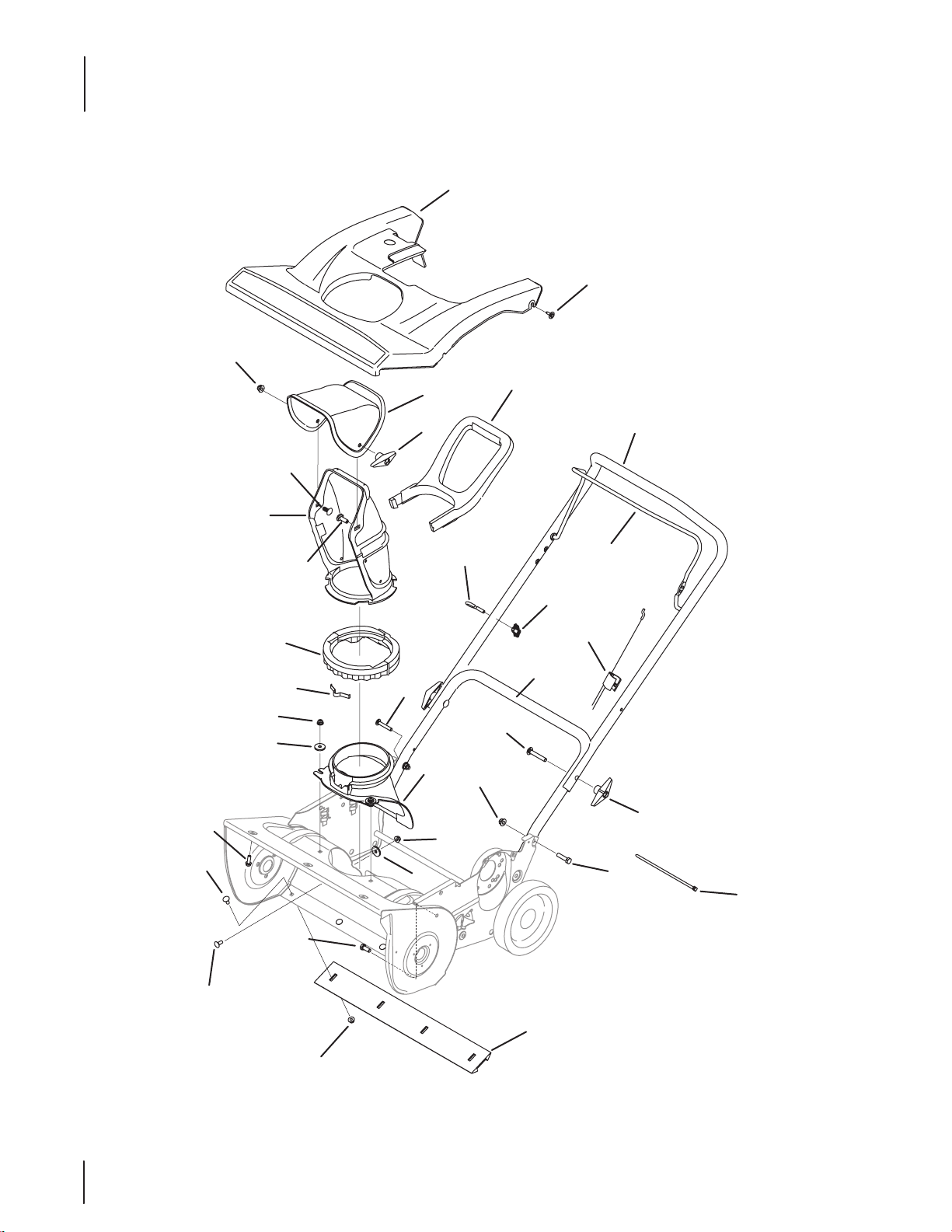
Shroud, Chute, & Handle
1
2
13
12
20
14
19
4
27
21
3
13
17
7
6
10
23
26
5
24
24
25
23
22
9
23
26
8
6
16
11
15
18
28
4
4
Page 5
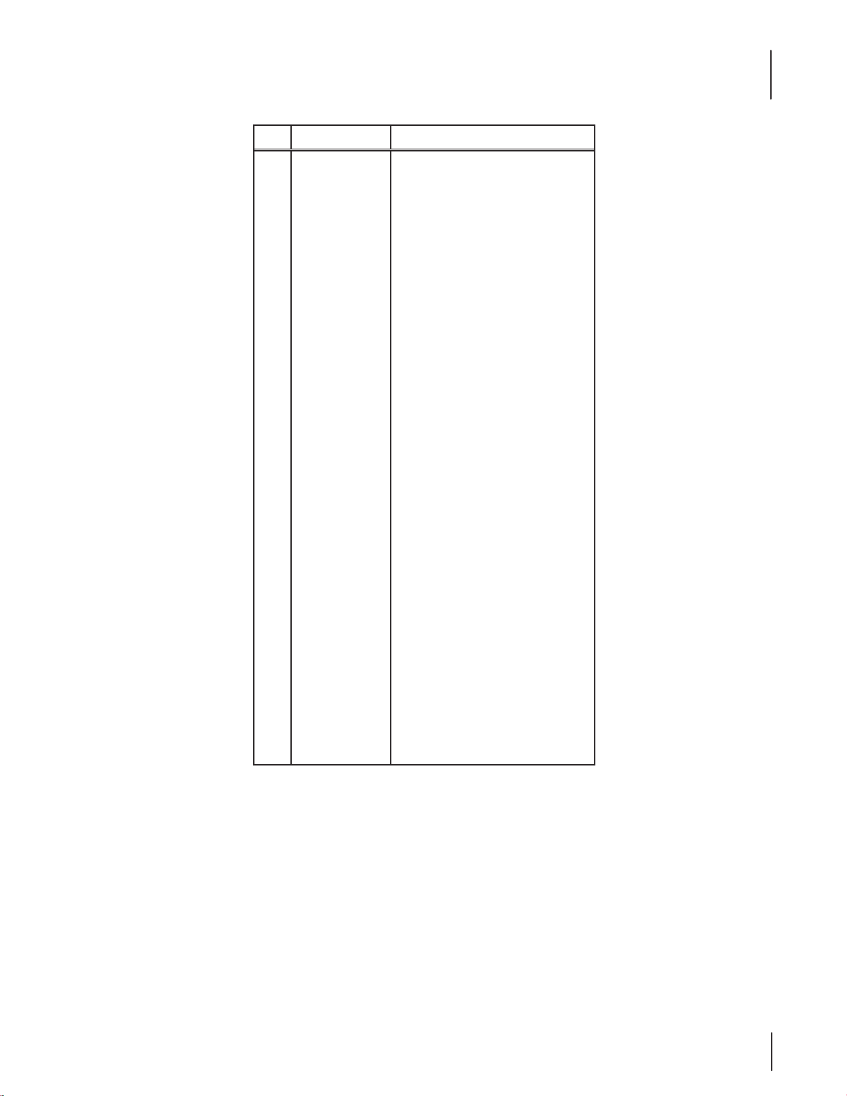
Ref.
Part Number Description
1. 731- 06 551 Shroud
68 4- 042 36A† Shroud
2. 710-04 669 Hex Washer Screw, 10-16 x .625
3. 71 0-12 05 Eye Bolt, ⁄-20
4. 720-0279 Knob Handle
5. 710 -0895 Hex Washer Screw, ⁄-15 x .750
6. 712 -0 4 06 3 Flange Lock Nut, ⁄-18
7. 710 -109 0 Hex Screw, ⁄-18 x 1.25
8. 931- 043 53 Lower Chute Ring
9. 9 3 2- 04 111 Chute Adjustment Spring
10. 931-04886 Chute Adapter
11. 931 -0 4127 Lower Chute, 5” Diameter
12 . 731-04 426A Upper Chute
13. 720-04072A Wing Knob
14. 731- 04388 A Chute Handle
15. 710 -0 451 Carriage Bolt, ⁄-18 x .750
16. 710- 04071 Carriage Bolt, ⁄-18 x 1.00
17. 72 5- 0157 Cable Tie, ⁄ x .05 x 7.4
18. 74 9 - 0 4 114 B Lower Handle
19. 710-04532 Carriage Screw, ⁄-18 x 2.00
20. 74 9- 0 4106 A Gullwing Handle
21. 747- 0 4159A Gullwing Control Bail
22. 7 31-1033 Shave Plate, 21”
23. 7 12- 04 06 4 Flange Lock Nut, ⁄-20
24. 710 -0 134 Carriage Screw, ⁄-20 x .62
25. 710- 3008 Hex Screw, ⁄-18 x .75
26. 93 6 -0 176 Flat Washer, .265 x .938 x .120
27. 746-04237 Clutch Cable
28. 7 10-18 82† Hex Screw, ⁄-18 x 1.50
Shroud, Chute, & Handle
† Model 2M5
5
5
Page 6

Drive System & Auger Assembly
43
34
35
16
13
11
12
23
14
10
3
27
28
24
25
32
31
26
4
5
21
20
6
7
6
8
9
15
30
33
37
40
38
39
41
36
37
29
42
18
19
17
1
22
2
2
47
50
51
48
49
46
46
52
45
44
6
6
Page 7

Drive System & Auger Assembly
Ref.
Part Number Description
1. 734-04033 Wheel, 8 x 2 (Gray)
73 4- 040 63A† Wheel, 7 x 1.5 (Gray)
2. 936-0326 Flat Washer, .510 x 1.000 x .125
3. 710 -0599 Hex Screw, ⁄-14 x .500
4. 710 -10 44 Hex Screw, ⁄-24 x 1.50
710-0627† Hex Bolt, ⁄-24 x .75
5. 736- 0247 Flat Washer, .406 x 1.25 x .157
73 6 -0 371† Bell Washer, .343 x .880 x .062
6. 756-0 4353 Pulley Half, 4L-V x 2.30 OD
95 6- 0416B † Pulley Half, .625 ID x .225 OD
7. 954- 04204 V-Belt
954 -0101A† V-Belt
8.
750-0 4303††
9.
750-05084††
10. 756-0 4232 V-Type Pulley, ⁄ x 35.7
11. 710-04 09 Hex Screw, ⁄-24 x 1.75
12 . 9 36 - 0119 Lock Washer, ⁄
13. 9 26 -015 4 Cable Tie, 7.5
14. 790-00334 Engine Support Bracket
790-0 0216† Engine Bracket
15. 710 -0 623 Hex Washer Screw, ⁄-16 x .50
16. 750-04297B Spacer, .875 x .320 x 1.027
17. 710-0896 Hex Washer Screw, ⁄-14 x .625
18. 710 -0653 Hex Washer Screw, ⁄-20 x .375
19. 790-00045C Belt Cover
684-04357† Belt Cover
20. 710- 0106 Hex Screw, ⁄-20 x 1.25
21. 750-0 4571 Shoulder Spacer, .260 x .785 x .538
22. 684-04168 Pulley Assembly, 1.917 OD
23. 7 12- 04 06 3 Flange Lock Nut, ⁄-18
24. 74 8- 02 34 Shoulder Spacer
Spacer, .875 ID x 1.185 OD
Spacer, .88 ID x 1.18 OD x .74 Lg.
Ref.
Part Number Description
25. 790-00238A Idler Bracket w/ Brake
26. 712 -0 4 06 4 Flange Lock Nut, ⁄-2 0
27. 790-00249 Bearing Cup
28. 741 -0 4188 A Ball Bearing, 1.25 x 37 x 12.6301
29. 710 -0642 Hex Screw, ⁄-20 x .750
30. 936-0329 Lock Washer, ⁄
31. 738 -0924A Shoulder Screw, .340 x .335 x ⁄-28
32. 756 -0625 Cable Roller
33. 9 36 - 0176 Flat Washer, .265 x .938 x .120
34. 712-0896 Hex Lock Nut, ⁄-28
35. 93 2- 035 7A Extension Spring, .33 OD x 1.12
36. 684 -04252 Auger Assembly, 21”
684- 04227† Auger Assembly, 21”
37. 710-05058 Hex Screw, ⁄-14 x .75
38. 735-04033 Rubber Pad
39. 735-04032 Spiral Crescent
40. 750 -04758 RH Spacer
41. 750 -04757 LH Spacer
42. 726 -0299 Push Cap, ⁄
43. 684 -04 314 Auger Housing
44. 7 10- 07 51† Hex Bolt, ⁄-20 x .620
45. 712 -0 4 06 4† Flange Lock Nut, ⁄-20
46. 726-0205† Hose Clamp, .490
47. 726-0233† Push Nut, .25 ID x .50 OD
48. 747-0 4236† Fuel Tank Support Wire
49. 951-10 023 † Fuel Tank, 2 Qt.
50. 7 51-104 87† Fuel Cap
51. 79 0 -0 0134 † Fuel Tank Bracket
52. 751 -1034 9† Fuel Line Hose
NS
92 9- 00 71A^††
Extension Cord
† Model 2M5
†† Model 2P5
^ Not Shown
7
7
Page 8

123cc 161-JWA Engine
97
1
5
31
34
4
9
80
8
6
10
92
38
36
89
41
37
20
29
30
32
33
96
39
87
90
94
69
68
56
58
59
57
52
53
70
72
82
48
73
77
71
50
51
71
12
75
108
11
55
54
76
79
62
40
78
93
7
14
13
60
17
16
61
74
81
47
45
15
64
63
84
79
95
40
22
46
44
43
85
110
23
24
83
67
65
64
66
18
20
21
88
19
25
91
28
26
106
103
109
105
102
98
100
99
104
101
107
42
41
8
Page 9

123cc 161-JWA Engine
Ref.
No.
1 710-04920 Flange Bolt
8 715 -0 40 92 Dowel Pin, 7 x 14
12 714 - 04 074 Governor Arm Clip
16 710-04906 Drain Plug Bolt
17 736-04440 Drain Plug Washer
18 951-10958 Ignition Coil
19 95 1- 1110 2 Flywheel Bae
20 710 -04 919 Flange Bolt
21 9 51-1090 8 Flywheel
22 951-10910 Cooling Fan
23 95 1- 10 9 11 Starter Cup
24 7 12- 042 09 Nut
25 95 1- 1110 7 Blower Housing
26 710 -04 914 Flange Bolt
28 731-05696 Recoil Starter Handle
29 71 2- 04 211 Nut
30 9 51 -1110 6 Governor Arm Bracket
31 710- 049 08 Bolt
32 951-10954 Throttle Return Spring
33 9 51 -1115 2 Governor Rod
34 951-10953 Governor Return Spring
36 9 51 -1110 3 Cover Shield
37 9 51 -111 0 4 Governor Spring Bracket
38 710-04921 Flange Bolt
39 95 1-109 01 Muer Assembly
41 712 -0 4212 Nut
42 9 51-109 62 Intake Heater Box Base
43 95 1-109 61 Intake Heater Box
44 71 0- 0 4913 Bolt
46 9 51-106 39 Primer
47 951-10956 Carburetor Assembly
50 710-049 02 Pivot Bolt
52 7 51 -1112 3 Valve Adjusting Nut
53 7 51 -1112 4 Pivot Locking Nut
61 951 -10913 Push Rod Kit
68 710- 04916 Bolt
69 9 51 -110 5 4 A Valve Cover
71 710 -0 4922 Bolt
72 731- 07059 Breather Hose
73 951-10292 Spark Plug
Part No. Description
Ref.
No.
75 9 51-106 57 Muer Stud Assembly
77 715 -0 40 90 Dowel Pin, 10 x 16
78 710 -0490 9 Carburetor Studs
80 7 15- 04 08 9 Dowel Pin, 9 x 14
82 72 6- 041 01 Hose Clamp
83 710 -04916 Bolt
85 9 51 -1110 5 Cylinder Bae
87 712 - 042 10 Nut
88 710-0 4918 Flange Bolt
90 951-10959 Muer Gasket
91 951-10955 Recoil Starter Assembly
92 951-10307 Flywheel Key
96 951-10957 Dipstick Assembly
108 9 51-10 912 Valve Kit
110 710 -04928 Bolt
NS 731- 0563 2 Ignition Key
— 951-11095 Crankcase Cover Kit
4 — Crankcase Cover
9 — Case Cover Gasket
96 951-10957 Dipstick Assembly
— 951-10951A Gasket Kit - Complete
5 — Oil Seal
9 — Crankcase Cover Gasket
11 — O-ring, 5.2 x 1.9
45 — Carburetor Gasket
70 — Head Cover Gasket
76 — Cylinder Head Gasket
79 — Carburetor Insulator Gasket
81 — Packing
84 — Oil Seal, 22 x 35 x 7
90 951-10959 Muer Gasket
95 951 -10370 Oil Drain Plug and Washer Assembly
96 951-10957 Dipstick Assembly
— 951-10952A Gasket Kit - External
70 — Head Cover Gasket
79 — Carburetor Insulator Gasket
81 — Packing
90 951-10959 Muer Gasket
95 951 -10370 Oil Drain Plug and Washer Assembly
96 951-10957 Dipstick Assembly
Part No. Description
9
Page 10

123cc 161-JWA Engine
Ref.
No.
— 9 51 -11 09 7 Crankcase Kit
14 — Bearing
15 — Crankcase Complete
84 — Oil Seal
— 9 51 -11 09 6 Crankshaft Kit
6 — Bearing
7 — Crankshaft Assembly
14 — Bearing
92 951-10307 Flywheel Key
93 95 1-109 48 Carburetor Kit - Major
98 — Float Pin
99 — Needle Valve Spring
100 — Needle Valve
101 — Bowl Gasket
102 — Main Jet
103 — Fuel Drain Plug Gasket
104 — Float
105 — Main Nozzle
106 — Idle Speed Adjusting Screw
107 — O-Ring- Main Cup Bolt
109 — Throttle Shaft Dust Seal
94 9 51-109 49A Cylinder Head Assembly
40 — Carburetor Insulator Plate
50 710-049 02 Pivot Bolt
51 — Rocker Arm
52 7 51 -1112 3 Valve Adjusting Nut
53 7 51 -1112 4 Pivot Locking Nut
56 — Valve Spring
57 — Intake Valve Spring Seat
58 — Exhaust Valve Spring Seat
59 — Exhaust Valve Adjuster
62 — Push Rod Guide Plate
70 — Head Cover Gasket
74 — Cylinder Head - Complete
76 — Cylinder Head Gasket
77 715 -0 40 90 Dowel Pin, 10 x 16
79 — Carburetor Insulator Gasket
90 951-10959 Muer Gasket
108 9 51-10 912 Valve Kit
Part No. Description
Ref.
No.
— 9 51 -11 06 3 A Valve Cover Kit
69 9 51 -110 5 4 A Valve Cover
70 — Valve Cover Gasket
95 951 -10370 Oil Drain Plug and Washer Assembly
16 710-04906 Oil Drain Plug
17 736-04440 Oil Drain Plug Washer
97 951-10950A Short Block Assembly
1 710-04920 Flange Bolt
4 — Crankcase Cover
5 — Oil Seal
6 — Bearing
7 — Crankshaft Assembly
8 715 -0 40 92 Dowel Pin, 7 x 14
9 — Case Cover Gasket
10 — Governor Assembly
11 — O-ring Gov. Shaft
12 714 - 04 074 Pin Lock
13 — Governor Arm Shaft
14 — Bearing
15 — Crankcase Complete
16 710-04906 Oil Drain Plug
17 736-04440 Oil Drain Plug Washer
40 — Carburetor Insulator Plate
45 — Heat Pipe Intake Gasket
48 — Camshaft Assembly
60 — Valve Lifter
61 951 -10913 Push Rod Kit
63 — Piston Ring Set - Oil
64 — Piston Pin Clip
65 — Piston
66 — Piston Pin
67 — Connecting Rod Complete
70 — Head Cover Gasket
76 — Cylinder Head Gasket
79 — Carburetor Insulator Plate Gasket
80 7 15- 04 08 9 Dowel Pin
84 — Oil Seal
90 951-10959 Muer Gasket
92 951-10307 Flywheel Key
96 951-10957 Dipstick Assembly
Part No. Description
10
Page 11

This page left intentionally blank.
11
Page 12

208 cc 270-SU Engine
115
122
68
55
87
34
127
43
66
88
62
60
25
25
58
89
25
65
36
53
45
64
26
92
129
45
124
126
126
67
26
44
128
123
125
125
37
57
37
26
77
38
80
26
39
76
78
85
79
95
40
93
26
26
93
94
81
45
45
143
94
96
113
49
47
130
110
109
72
90
47
32
33
156
26
110
98
99
98
101
97
83
26
26
23
26
23
26
24
22
22
15
13
12
11
150
141
132
5
149
133
158
135
137
140
6
13
7
3
148
1
1
1
1
2
33
151
152
153
159
130
100
14
8
7
146
147
138
131
105
84
10
134
136
139
154
142
8
4
27
19
21
145
104
20
9
10
102
26
15
28
56
16
155
26
15
30
18
29
26
84
74
15
73
75
72
72
72
46
17
31
63
71
69
53
34
121
117
64
48
118
119
86
157
52
35
104
70
61
59
54
82
12
Page 13

208 cc 270-SU Engine
Ref.
No.
1 710-0 4968 Bolt
2 9 5 1- 110 5 4 Valve Cover
3 7 31-0 7059 Breather Hose
4 7 26 -0 4101 Hose Clamp
7 7 5 1-111 24 Pivot Locking Nut
8 7 5 1-111 23 Valve Adjusting Nut
10 710- 049 02 Pivot Bolt
15 710 -04933 Bolt
18 951-10292 Spark Plug
19 9 51 -112 8 2 Muer Assembly
20 710-05001 Stud
21 9 5 1- 112 89 Muer Gasket
22 712 -0 4214 Nut
23 710 -0 4914 Bolt
24 9 51 -11111 Exhaust Pipe Shield
25 710-0 4940 Bolt
26 710 - 04 915 Bolt
27 951-10 642 A Muer Shroud
28 710-049 39 Stud, M6 x117
29 710 -04 910 Stud, M6 x 105
33 951-10 638 A Carburetor Assembly
35 9 51 -11112 Choke Control Bracket
36 951-106 34 Engine Shroud
37 7 12- 04 213 Nut
38 9 51 -112 8 4 Choke Knob
39 95 1-10757 Throttle Control Knob
40 951-10 637 Ignition Switch
43 95 1-106 40 Choke Push Rod
44 9 51-10635 Heater Box
45 710 - 04919 Bolt
47 9 51-106 48 Push Rod Kit (incl. intk and exhst rod)
49 715 - 04 09 0 Dowel Pin
57 9 51 -11113 Air Shield
59 9 51 -11 35 6 Governor Arm Shaft
60 736-04461 Washer
62 714 - 04 074 Cotter Pin
64 9 5 1- 113 69 Radial Ball Bearing
65 951 -1030 7 Flywheel Key
68 715- 04 092 Dowel Pin, 7 x 14
69 715 -0 40 96 Dowel Pin, 9 x 14
Part No. Description
Ref.
No.
70 9 51 -113 7 1 Crankcase Cover Gasket
72 710-04932 Bolt
75 9 51 -11 36 8 Oil Seal
78 736-04440 Washer
80 95 1- 1137 0 Oil Seal
81 9 51-1064 6 Ignition Coil
82 9 51 -11110 Air Flow Shield
83 951 -1065 0 Fuel Line Kit (incl. clmps and fuel line)
84 95 1-11 73 1 Hose Clamp
85 951 -106 41 Oil Drain Ass’y, includes 77, 78, 79
86 951-10805 Flywheel
87 951-10909 Cooling Fan
88 95 1- 10 911 Starter Cup
89 712 -0 42 09 Nut
90 951-10 647 Valve Kit (incl. intk and exhst valve)
92 951-10 663 A Blower Housing
93 736 -04 455 Washer
94 710 -0 49 74 Bolt
95 951 -1065 8 Recoil Starter Assembly
96 731- 05632 Key
97 95 1-1075 8 Throttle Control Assembly
98 710- 05103 Bolt
99 95 1- 1110 8 Governor Shield
100 751-1193 5 Governor Spring
101 951-1 066 4 Throttle Return Spring
102 951-1 066 5 Governor Rod
104 712 -0 4212 Nut
105 710-0 4908 Bolt
109 951-1 066 2 Engine/Dipstick Cover
110 710 -0 4905 Bolt
113 75 1-11913 Dipstick Tube
115 75 1-11912 Dipstick
117 9 51-106 49 Fuel Cap Assembly
118 9 51-11933 Fuel Level Indicator
119 9 51-106 53B Fuel Tank
121 9 5 1-1111 4 Switch Housing Mounting Bracket
122 7 51-11934 O-Ring
123 710 -0 4965 Bolt, M4 x 55
124 710 -0 4935 Bolt, M4 x 60
125 710-0 5182 Bolt
Part No. Description
13
Page 14

208 cc 270-SU Engine
Ref.
No.
126 715-04088 Dowel Pin
127 9 51-1064 5A Electric Starter
128 710 -0 4979 Bolt
129 9 5 1-111 0 9 Blower Housing Shield
130 9 51-106 39A Primer
131 710 -0 4945 Bolt
132 710 -0 4938 Drain Bolt
143 731-05696 Starter Handle
155 9 51 -111 0 6 Governor Arm Bracket
156 9 51-11903 O-Ring
157 9 51 -11 6 8 0 Wire Clip
— 951-10 651 Fuel Tank Nipple (Not Shown)
— 952Z270-SU Engine, Complete
33 951-10 63 8A Carburetor Assembly
130 951 -1063 9A Primer
131 710-04945 Bolt
132 710-04938 Drain Bolt
133 — Gasket, Throttle Plate
134 — Float Pin
135 — Emulsion Tube
136 — Needle Valve
137 — Main Jet
138 — Needle Valve Spring
139 — Float
140 951-11589 Fuel Bowl Gasket
141 95 1- 113 4 9 Fuel Drain Plug Gasket
142 9 5 1- 113 4 8 Fuel Bowl Gasket
146 — Choke Shaft
147 — Choke Plate
148 — Throttle Shaft
149 — Throttle Plate
150 — Screw, M3×5
151 — Lock Washer
152 — Idle Jet Assembly
153 — Idle Speed Adjusting Screw
154 — Fuel Bowl
158 751-119 06 Hose Clamp
159 751 -120 06 Primer Hose
Part No. Description
Ref.
No.
— 9 5 1- 110 6 0A Short Block Assembly (Not Shown)
5 9 51 -11 56 5 Head Cover Gasket
21 9 51 -11 28 9 Muer Gasket
30 9 51 -11 56 7 Carburetor Insulator Gasket
31 7 51 -11 89 6 Carburetor Insulator Plate
46 9 51 -115 7 2 Cylinder Head Gasket
48 75 1- 118 9 9 Ta pp et
49 7 15- 04 09 0 Dowel Pin
52 9 51 -112 5 3 Piston Ring Set
53 9 51 -116 3 2 Piston Pin Snap Ring
54 75 1-120 07 Piston
55 9 51 -116 3 3 Piston Pin
58 9 51 -11 57 3 Connecting Rod Assembly
59 9 51 -113 5 6 Governor Arm Shaft
60 736-04461 Washer
61 7 51-11902 Governor Seal
62 7 14- 0 4074 Cotter Pin
63 9 5 1-11 57 5 Camshaft Assembly
64 9 51 -113 6 9 Radial Ball Bearing
65 9 51-103 07 Flywheel Key
66 — Crankshaft Assembly
67 9 51 -115 7 6 Governor Gear/Shaft Assembly
68 715 - 04 092 Dowel Pin, 7 x 14
69 7 15- 04 09 6 Dowel Pin, 9 x 14
70 9 51 -113 71 Crankcase Cover Gasket
71 — Case Cover
72 710 -0 4932 Bolt
73 9 5 1-11 57 7 O-Ring
74 — Oil Fill Plug
75 9 51 -113 6 8 Oil Seal
76 — Crankcase
77 9 51 -11 35 0 Oil Drain Pipe
78 736-04440 Washer
79 710-04906 Oil Drain Plug
80 9 51 -113 7 0 Oil Seal
145 95 1-106 57 Muer Stud Assembly
20 710-05001 Stud
Part No. Description
14
Page 15

208 cc 270-SU Engine
Ref.
No.
— 9 5 1- 110 21 Carburetor Kit, Major (Not Shown)
133 — Gasket, Throttle Plate
134 — Float Pin
135 — Emulsion Tube
136 — Needle Valve
137 — Main Jet
138 — Needle Valve Spring
139 — Float
140 — Fuel Bowl Gasket
141 — Fuel Drain Plug Gasket
142 — Fuel Bowl Gasket
— 9 51-10 661B Gasket Kit, External (Not Shown)
5 9 51 -11 56 5 Head Cover Gasket
21 9 51 -11 28 9 Muer Gasket
30 9 51 -11 56 7 Carburetor Insulator Gasket
31 7 51 -11 89 6 Carburetor Insulator Plate
32 75 1 -115 6 9A Carburetor Gasket
34 7 51 -118 9 7 Carburetor Gasket Plate
78 736-04440 Washer
— 9 5 1- 1124 6 Crankcase Cover Kit (Not Shown)
64 9 51 -113 6 9 Radial Ball Bearing
70 9 51 -113 71 Crankcase Cover Gasket
71 — Case Cover
72 — Cover Bolts
73 — O-Ring
74 — Oil Fill Plug
75 9 51 -113 6 8 Oil Seal
— 9 5 1- 1124 7 Crankshaft Kit (Not Shown)
64 9 51 -113 6 9 Radial Ball Bearing
65 9 51-103 07 Flywheel Key
66 — Crankshaft Assembly
75 9 51 -113 6 8 Oil Seal
80 9 51 -113 7 0 Oil Seal
— 9 5 1- 1124 9 Crankcase Kit (Not Shown)
61 7 51-11902 Governor Seal
64 9 51 -113 6 9 Radial Ball Bearing
70 9 51 -113 71 Crankcase Gasket
76 — Crankcase
80 9 51 -113 7 0 Oil Seal
Part No. Description
Ref.
No.
— 9 51-10 668 A Cylinder Head Assembly (Not Shown)
5 9 51 -11 56 5 Head Cover Gasket
6 751-12000 Intake Valve Spring Seat
7 7 51 -1112 4 Pivot Locking Nut
8 7 51 -1112 3 Valve Adjusting Nut
9 7 51 -11 89 3 Rocker Arm
10 710 -0 4902 Pivot Bolt
11 7 51-12 00 2 Exhaust Valve Adjuster
12 751 -120 03 Exhaust Valve Spring Seat
13 751 -120 04 Valve Spring
14 7 51 -11 8 94 Intake Valve Seal
16 7 51 -11 89 5 Push Rod Guide Plate
17 — Cylinder Head - Complete
21 9 51 -11 28 9 Muer Gasket
30 9 51 -11 56 7 Carburetor Insulator Gasket
31 7 51 -11 89 6 Carburetor Insulator Plate
46 9 51 -115 7 2 Cylinder Head Gasket
90 951 -106 47 Valve Kit
— 9 5 1- 110 59 A Gasket Kit, Complete (Not Shown)
5 9 51 -11 56 5 Head Cover Gasket
21 9 51 -11 28 9 Muer Gasket
30 9 51 -11 56 7 Carburetor Insulator Gasket
31 7 51 -11 89 6 Carburetor Insulator Plate
32 75 1 -115 6 9A Carburetor Gasket
34 7 51 -118 9 7 Carburetor Gasket Plate
46 9 51 -115 7 2 Cylinder Head Gasket
60 736-04461 Washer
61 7 51-11902 Governor Seal
62 7 14- 0 4074 Cotter Pin
70 9 51 -113 71 Crankcase Cover Gasket
75 9 51 -113 6 8 Oil Seal
78 736-04440 Washer
80 9 51 -113 7 0 Oil Seal
— 9 5 1- 110 6 3 Valve Cover Kit (Not Shown)
2 9 51 -11 0 54 Valve Cover
5 9 51 -11 56 5 Head Cover Gasket
56 9 51 -11 28 3 Oil FIll Plug Assembly
73 9 5 1-11 57 7 O-Ring
74 — Oil FIll Plug
Part No. Description
15
Page 16

To order replacement parts or locate your nearest service dealer call Customer Support at (800) 828-5500.
or visit www.troybilt.com to find the nearest authorized dealer in your area.
TROY-BILT LLC, P.O. BOX 361131 CLEVELAND, OHIO 44136-0019
 Loading...